LITE ON TECHNOLOGY WN4615L 802.11n, 2.4G 1T1R Wireless LAN USB Module User Manual LiteOn Technology Corp
LITE-ON Technology Corp. 802.11n, 2.4G 1T1R Wireless LAN USB Module LiteOn Technology Corp
User Manual
Page 1/12
USER MANUAL
802.11n, 2.4G 1T1R Wireless LAN USB Module
WN4615L
Realtek RTL8188ETV
Version 1.1
Change History
Revision
Date
Author
Change List
Version 1.0
2014/05/05
Ben J Chen
Preliminary
Version 1.1
2015/01/07
Ben J Chen
Update Power Consumption
Update Pin Assignment
* This document contains confidential proprietary information and is property of LTC. The contents of
this document should not be disclosed to unauthorized persons without the written consent of LTC.

Page 3/12
CONTENT
PRODUCT FEATURES .................................................................................................................... 4
WI-FI FEATURE ...................................................................................................................................... 4
PRODUCT SPECIFICATIONS ........................................................................................................ 5
MAIN CHIPSET ....................................................................................................................................... 5
FUNCTIONAL SPECIFICATIONS ............................................................................................................... 5
INRUSH CURRENT .......................................................................................................................... 6
PIN ASSIGNMENT ............................................................................................................................ 7
USB CONNECTOR SPEC ................................................................................................................. 7
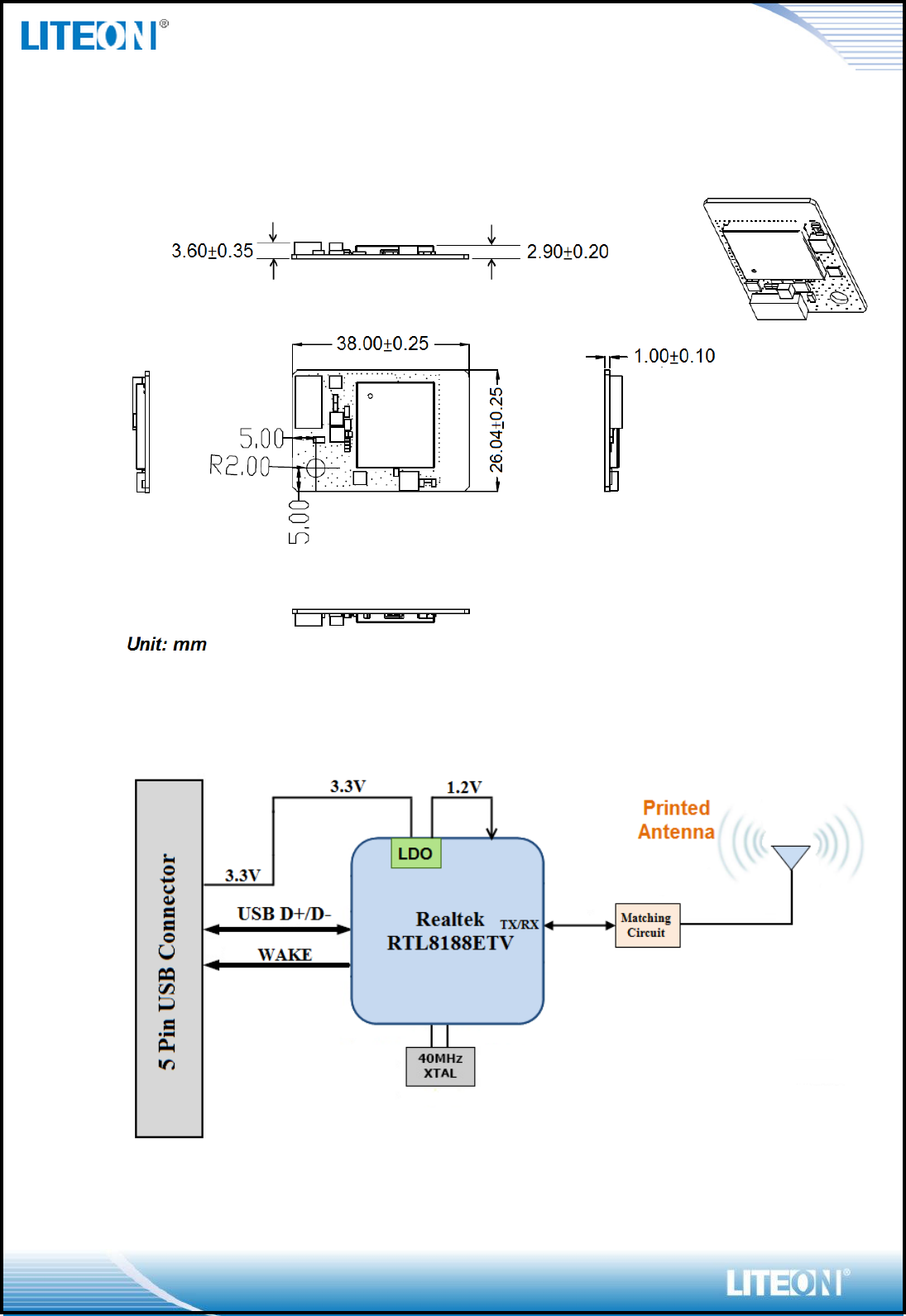
MECHANICAL .................................................................................................................................. 8
BLOCK DIAGRAM ........................................................................................................................... 8
PRINTED ANTENNA SPEC ............................................................................................................. 9
EEPROM INFORMATION ............................................................................................................ 11
ENVIRONMENTAL ........................................................................................................................ 11
OPERATING .......................................................................................................................................... 11
STORAGE .............................................................................................................................................. 11
PACKING DRAWING .................................................................................................................... 11

Page 4/12
PRODUCT FEATURES
Wi-Fi Feature
Operate at ISM frequency Band (2.4GHz)
IEEE Standards Support, 802.11b, 802.11g and 802.11n
CMOS MAC, Baseband PHY, and RF in a single chip for IEEE 802.11b/g/n
compatible WLAN
Complies with USB Specification 2.0, support Full-speed(12Mbps) and
High-Speed(480Mbps)
Enterprise level security supporting: WPA, WPA2
Support 1 transmission and 1 receiving, transmission rate can up to 150Mbps
(Physical Rate) in downstream and upstream
RoHS compliance
Low Halogen compliance
Page 5/12
PRODUCT SPECIFICATIONS
MAIN CHIPSET
Realtek RTL8188ETV
FUNCTIONAL SPECIFICATIONS
Wi-Fi Function
Standard
IEEE802.11b; IEEE 802.11g; IEEE 802.11n
Bus Interface
USB 2.0
Data Rate
802.11b:
11, 5.5, 2, 1 Mbps
802.11g:
54, 48, 36, 24, 18, 12, 9, 6 Mbps
802.11n:
MCS 0 to 7 for HT20MHz
MCS 0 to 7 for HT40MHz
Media Access Control
CSMA/CA with ACK
Modulation Techniques
802.11b:
CCK, DQPSK, DBPSK
802.11g:
64QAM, 16QAM, QPSK, BPSK
802.11n:
64QAM, 16QAM, QPSK, BPSK
Network Architecture
Ad-hoc mode (Peer-to-Peer)
Infrastructure mode
Operation Channel
2.4GHz
11: (Ch. 1-11) – United States
13: (Ch. 1-13) – Europe
14: (Ch. 1-14) – Japan
Frequency Range
802.11bg
2.400 ~ 2.4835 GHz
Transmit Output
Power – 1x1
(Tolerance: ±1.5dBm)
802.11b:
15 dBm@1Mbps
15 dBm@11Mbps
802.11g:
14 dBm@6Mbps
14 dBm@54Mbps
802.11n:
20MHz:
14 dBm@MCS0
14 dBm@MCS7
40MHz:
12 dBm@MCS0
12 dBm@MCS7
Receiver Sensitivity
802.11b:
-82 dBm@11Mbps
802.11g:
-69 dBm@54Mbps
802.11n:
20MHz
Page 6/12
-68 dBm@MCS7
40MHz
-65 dBm@MCS7
Security
WEP 64&128 bit, WPA, WPA-PSK, WPA2, WPA2-PSK,
WPS, IEEE 802.1X, IEEE 802.11i
Operating Voltage
3.3 V ±9% I/O supply voltage
OS Supported
Microsoft Windows Win7/Win8/Win8.1; Linux based
Power Consumption
Test Condition:
- Operate at HT40
- File Transmission
Average
Max
TX Mode:
300 mA
RX Mode:
180 mA
Standby Mode:
160 mA
600mA
Antenna Type
Printed Antenna
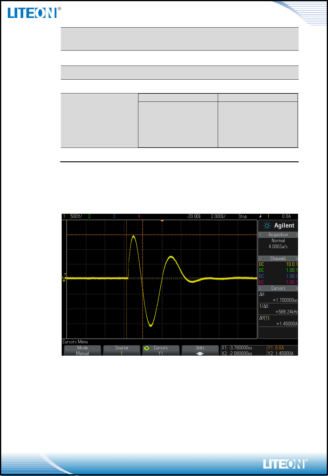
INRUSH CURRENT
The MAX is about 1.45A and during time is about 1.7us.
Page 7/12
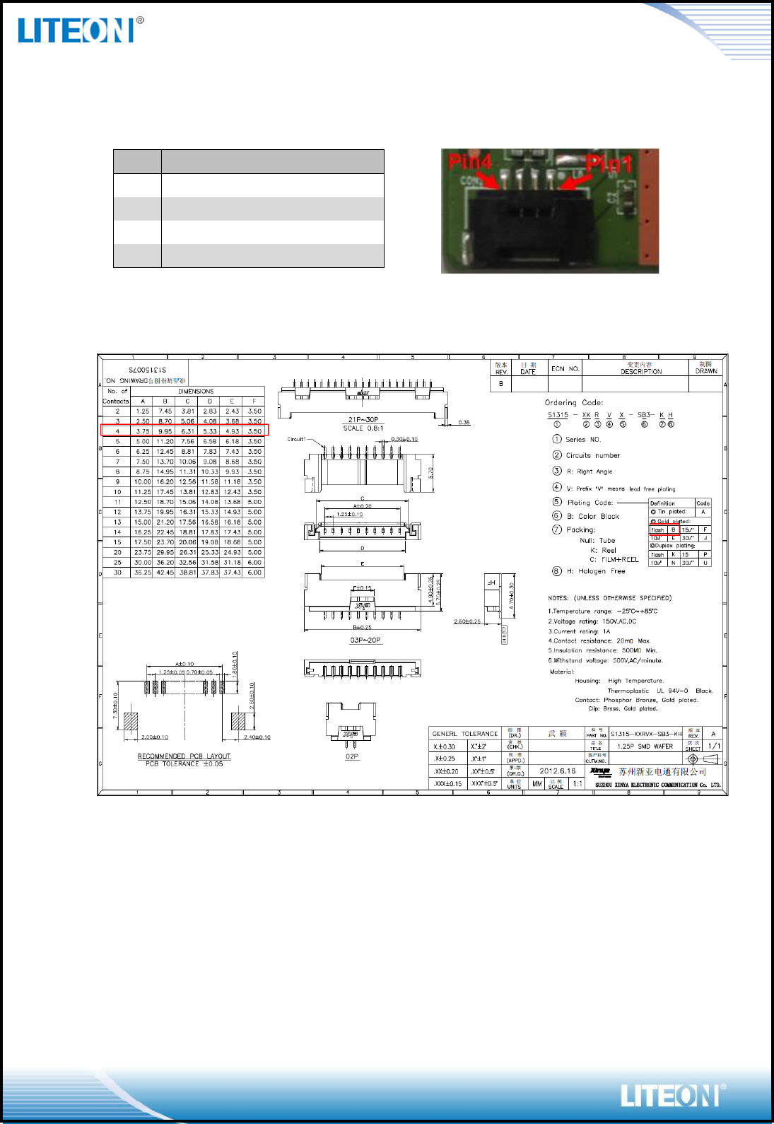
PIN ASSIGNMENT
USB CONNECTOR SPEC
Pin.
Pin Define
Status
1
+3.3V
YES
2
USB_D-
YES
3
USB_D+
YES
4
GND
YES
Page 8/12
MECHANICAL
BLOCK DIAGRAM
Page 9/12
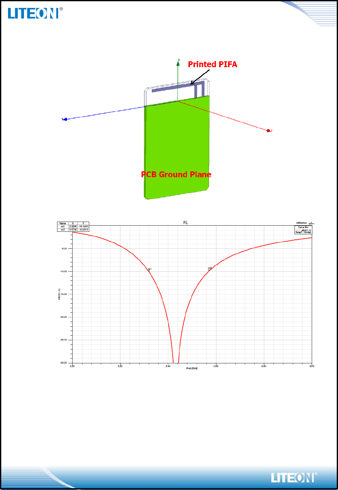
PRINTED ANTENNA SPEC
Page 10/12
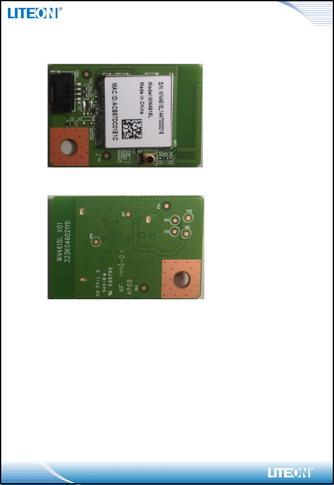
MODULE PHOTO
Top Side
Bottom Side
Page 11/12
EEPROM INFORMATION
Reg Domain
WorldWide13
Channels 1-11 with active scan, 12-13 with
passive scan
0x20
Vendor ID
0x0BDA
Device ID
0x0179
ENVIRONMENTAL
OPERATING
Operating Temperature: 0 to 70 C (32 to 158 F)
Relative Humidity: 5-90% (non-condensing)
STORAGE
Temperature: -40 to 80 C (-40 to 176 F)
Relative Humidity: 5-95% (non-condensing)
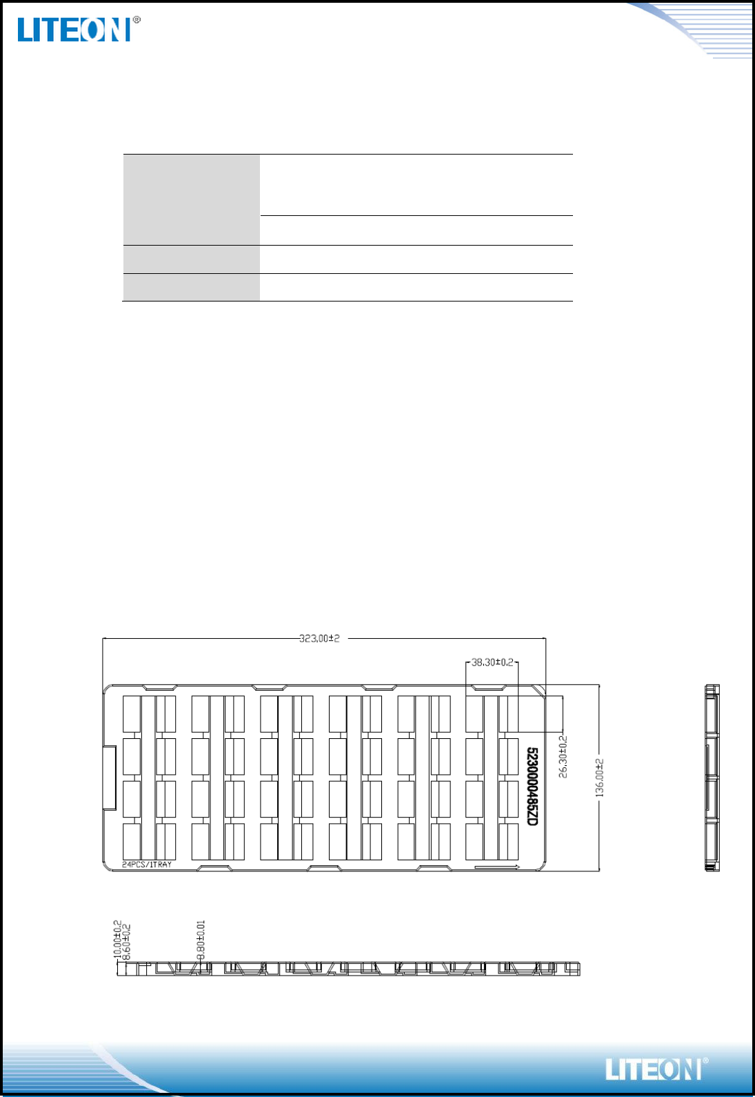
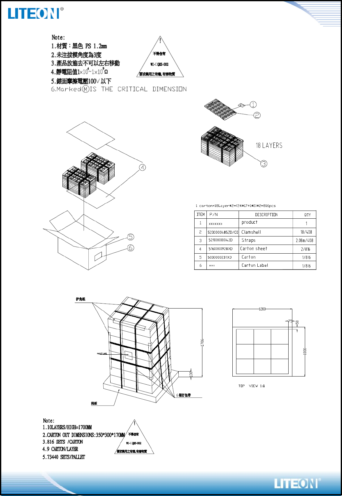
PACKING DRAWING
Tray
Page 12/12
This device complies with Part 15 of the FCC Rules. Operation is subject to the
following two conditions: (1) this device may not cause harmful interference and (2)
this device must accept any interference received, including interference that may
cause undesired operation.
This equipment has been tested and found to comply with the limits for a Class B digi
tal device, pursuant to part 15 of the FCC rules. These limits are designed to provide r
easonable protection against harmful interference in a residential installation. This equ
ipment generates, uses and can radiate radio frequency energy and, if not installed and
used in accordance with the instructions, may cause harmful interference to radio co
mmunications. However, there is no guarantee that interference will not occur in a par
ticular installation. If this equipment does cause harmful interference to radio or televi
sion reception, which can be determined by turning the equipment off and on, the user
is encouraged to try to correct the interference by one or more of the following measu
res: Reorient or relocate the receiving antenna.
Increase the separation between the equipment and receiver.
Connect the equipment into an outlet on a circuit different from that to which the recei
ver is connected. Consult the dealer or an experienced radio/TV technician for help.
You are cautioned that changes or modifications not expressly approved by the party r
esponsible for compliance could void your authority to operate the equipment.
FCC RF Radiation Exposure Statement: 1. This Transmitter must not be co
located or operating in conjunction with any other antenna or transmitter. 2.
This equipment complies with FCC RF radiation exposure limits set forth for an unco
ntrolled environment. This equipment should be installed and operated with a minimu
m distance of 20 centimeters between the radiator and your body.
Information to OEM integrator
The OEM integrator has to be aware not to provide information to the end user regard
ing how to install or remove this RF module in the user manual of the end product. Th
e user manual which is provided by OEM integrators for end users must include the fo
llowing information in a prominent location.
1. To comply with FCC RF exposure compliance requirements, the antenna used for t
his
transmitter must be installed to provide a separation distance of at least 20 cm from
all persons and must not be co- located or operating in conjunction with any other
antenna or transmitter, except in accordance with FCC multitransmitter product
transmitter product procedures.
2. Only those antennas with same type and lesser gain filed under this FCC ID numbe
r can be used with this device.
3. The regulatory label on the final system must include the statement: “Contains FCC
ID:PPQ-WN4615L “.
4. The final system integrator must ensure there is no instruction provided in the user
manual or customer documentation indicating how to install or remove the transmitter
module except such device has implemented two
ways authentication between module and the host system.