LITE ON TECHNOLOGY WP8721 Access Point User Manual
LITE-ON Technology Corp. Access Point
UserManual.wiki
>
LITE ON TECHNOLOGY
>
WP8721 User Manual
User Manual
Navigation menu
Upload a User Manual
Namespaces
Wiki Guide
HTML
PDF
Info
Views
User Manual
Discussion / Help
Navigation
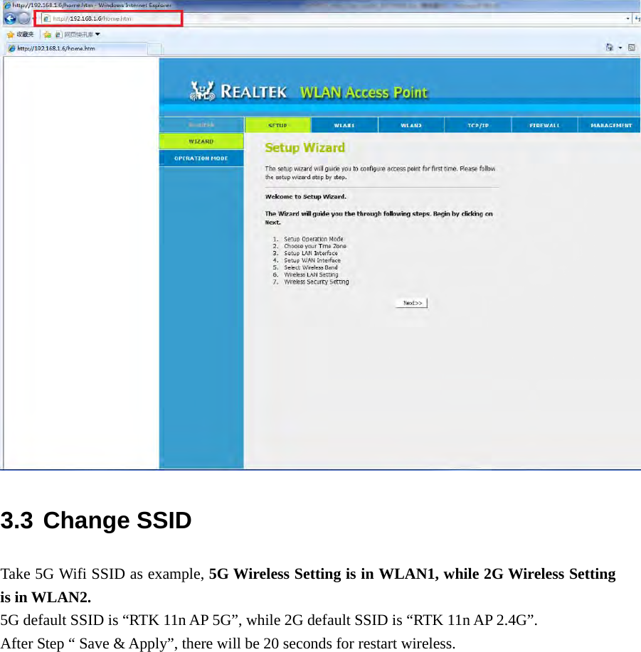
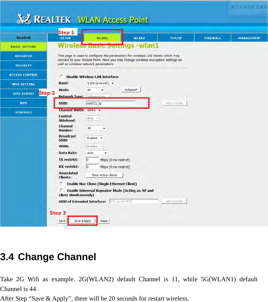
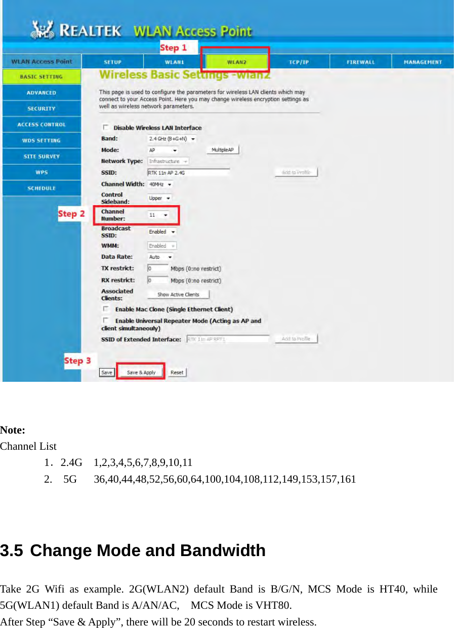
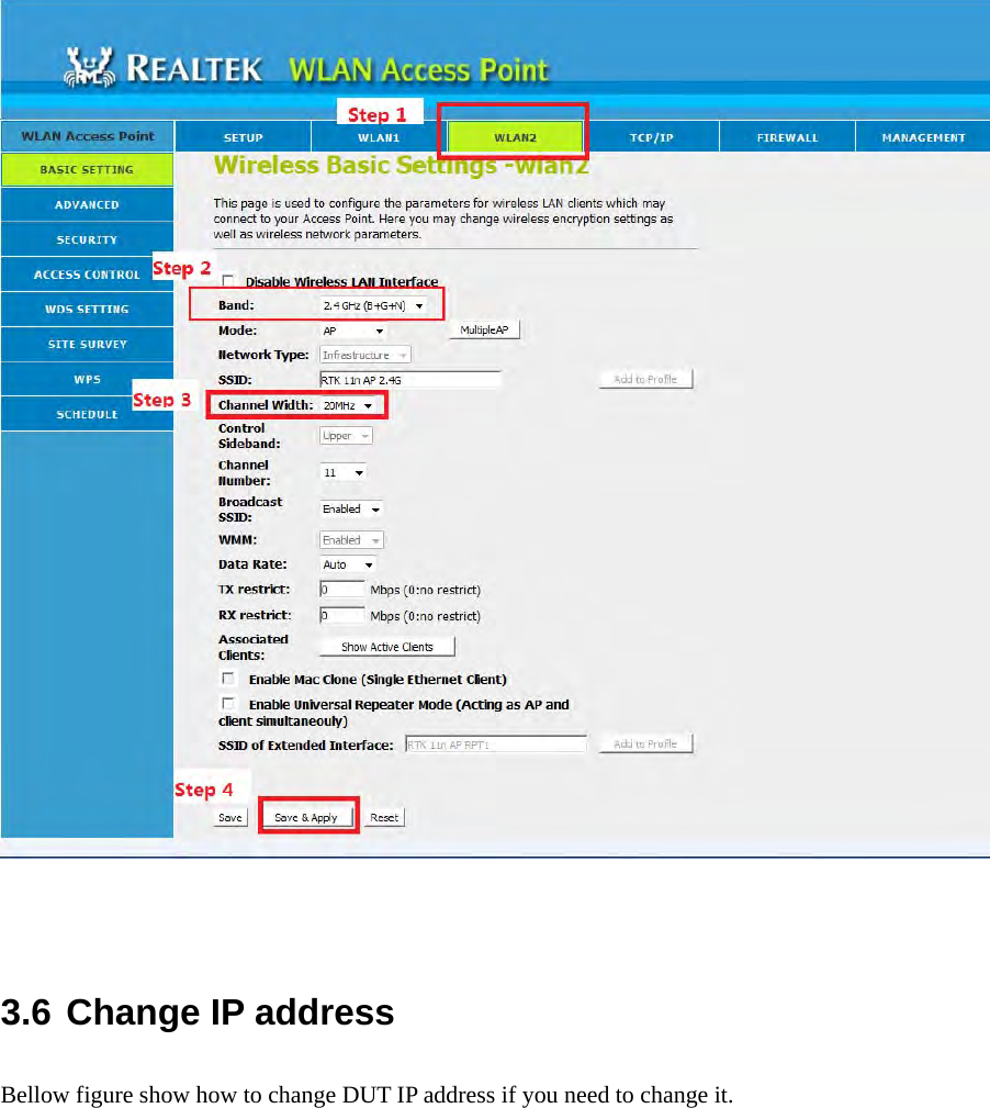
![[End of file]](https://usermanual.wiki/LITE-ON-TECHNOLOGY/WP8721/User-Guide-3476157-Page-12.png)