LITE ON TECHNOLOGY WP8721 Access Point User Manual
LITE-ON Technology Corp. Access Point
User Manual
WP8721 Access Point
LITE-ON
User Guide
Content
1Introduction...............................................................................................................................3
1.1Test Bench Setup...........................................................................................................3
2RF Test Mode (by RealTek MPTool)........................................................................................4
2.1Switch from AP mode to RF test mode.........................................................................4
2.2Run MP tool..................................................................................................................5
2.3Continuous Tx...............................................................................................................5
3AP mode....................................................................................................................................6
3.1Switch from RF test mode to AP mode.........................................................................6
3.2Login DUT....................................................................................................................7
3.3Change SSID.................................................................................................................8
3.4Change Channel............................................................................................................9
3.5Change Mode and Bandwidth.....................................................................................10
3.6Change IP address.......................................................................................................11
1 Introduction
This document describes how to start RF test mode or AP mode, under test firmware.
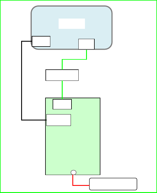
1.1 Test Bench Setup
1) DUT software version: WP8721_TestFW_Rv0.0.3_20170524
2) COM port configuration:
Bits per second / Data bits / Parity / Stop bits / Flow control: 38400/8/None/1/None
3) Power adapter: 802.3at/af PoE or 12V DC
4) DUT default IP address: 192.168.1.254 in AP mode; 192.168.1.6 in RF test
mode
5) Configure PC NIC IP address as 192.168.1.0 subnet, for example:
192.168.1.100.
DUT
Switch
Console
PC
COM GE1
GE1
DC Powe
r
2 RF Test Mode (by RealTek MPTool)
This chapter describes how to start RF test mode (especially continuous TX99 mode).
2.1 Switch from AP mode to RF test mode
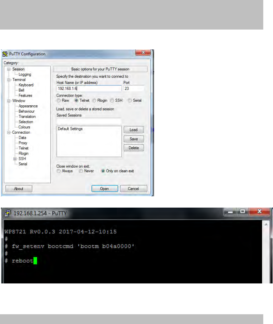
Please the default mode is AP model, can be switched to RF test mode:
In Linux:
#
#fw_setenvbootcmd'bootmb04a0000'
#reboot
Use telnet tool (e.g. putty) to login DUT and input command.
Or in u-boot (by serial console tool, e.g. putty):
8197F#
8197F# setenvbootcmd'bootmb04a0000';save;reset
8197F#
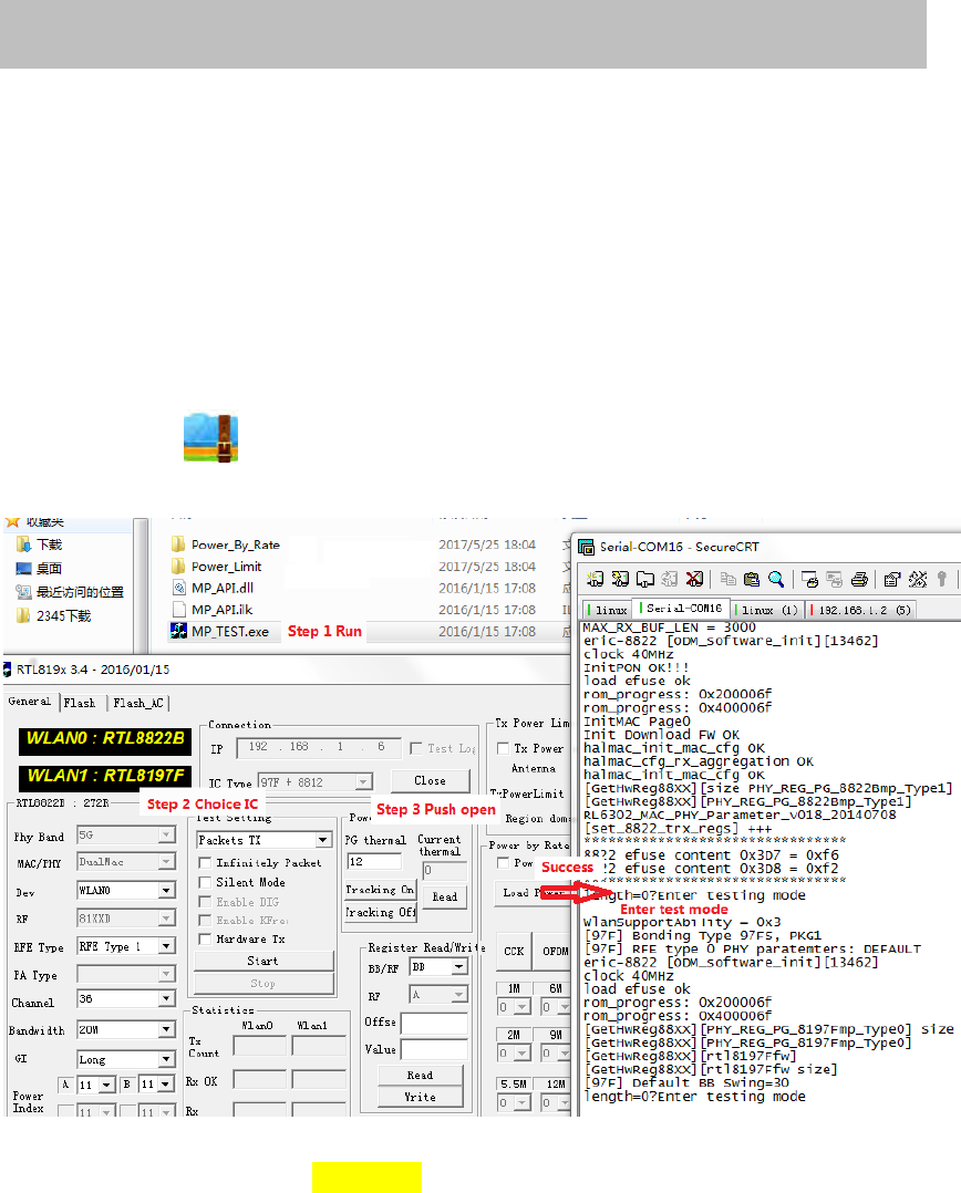
2.2 Run MP tool
Before running MP tool, make sure ping to 192.168.1.6 is OK.
Extract MP-Tool-v3.4-2016.0115.zip, run MP_TEST.exe.
00005076-MP-Tool-v3.4-2016.0115.zip
Note:
1. DUT IP address is 192.168.1.6 in RF test mode.
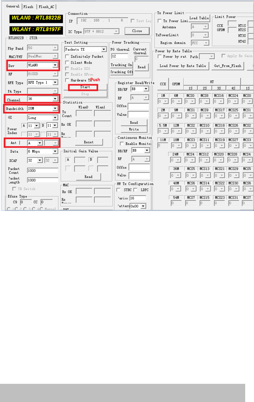
2.3 Continuous Tx
As shown in the bellow figure:
Dev, channel, bandwidth and ant can be changed. Then click Start to Tx continuously .
Note:
2. 5G Wireless interface is wlan0; 2.4G Wireless interface is wlan1.
3. Ant: A: chain-0; B: chain-1; A+B: chain0+1.
3 AP mode
3.1 Switch from RF test mode to AP mode
If current mode is RF test mode, can be switch to AP mode by bellow command. Please note the
default mode is AP.
In Linux:
#
#fw_setenvbootcmd'bootmb00a0000'
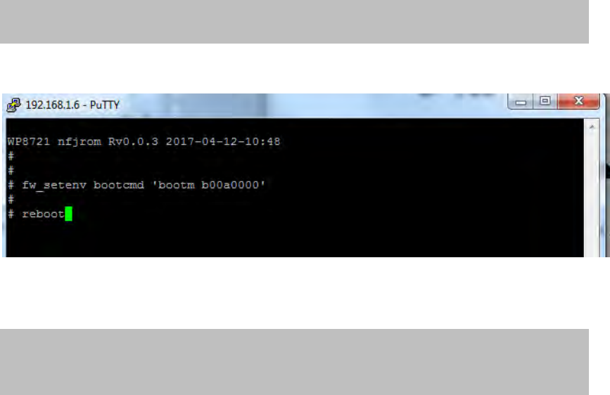
#reboot
#
Telnet login to 192.168.1.6:
Or in u-boot (by serial console tool, e.g. putty):
8197F#
8197F#setenvbootcmd'bootmb00a0000';save;reset
8197F#
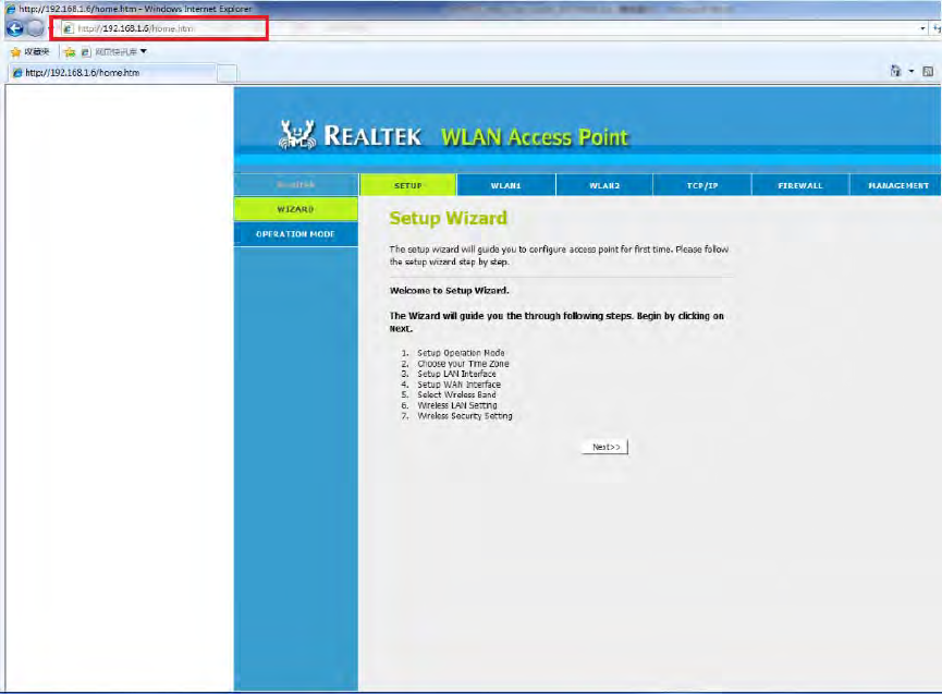
3.2 Login DUT
Input IP address in IE browser “192.168.1.254”, Web interface open as below:
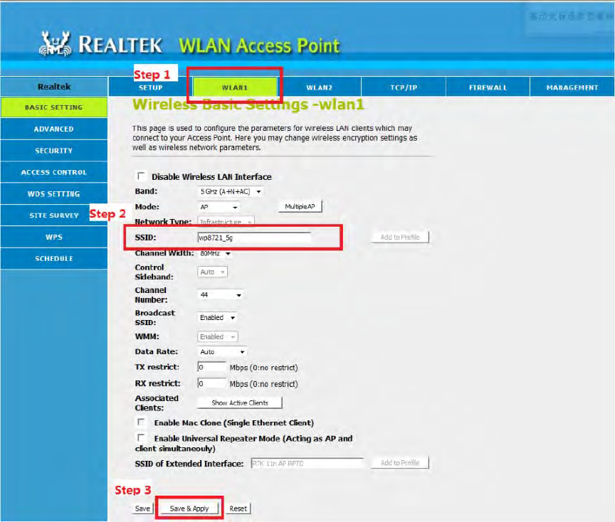
3.3 Change SSID
Take 5G Wifi SSID as example, 5G Wireless Setting is in WLAN1, while 2G Wireless Setting
is in WLAN2.
5G default SSID is “RTK 11n AP 5G”, while 2G default SSID is “RTK 11n AP 2.4G”.
After Step “ Save & Apply”, there will be 20 seconds for restart wireless.
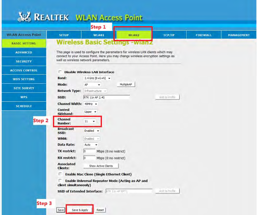
3.4 Change Channel
Take 2G Wifi as example. 2G(WLAN2) default Channel is 11, while 5G(WLAN1) default
Channel is 44.
After Step “Save & Apply”, there will be 20 seconds for restart wireless.
Note:
Channel List
1.2.4G 1,2,3,4,5,6,7,8,9,10,11
2. 5G 36,40,44,48,52,56,60,64,100,104,108,112,149,153,157,161
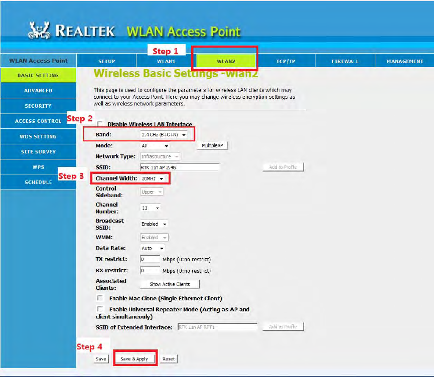
3.5 Change Mode and Bandwidth
Take 2G Wifi as example. 2G(WLAN2) default Band is B/G/N, MCS Mode is HT40, while
5G(WLAN1) default Band is A/AN/AC, MCS Mode is VHT80.
After Step “Save & Apply”, there will be 20 seconds to restart wireless.
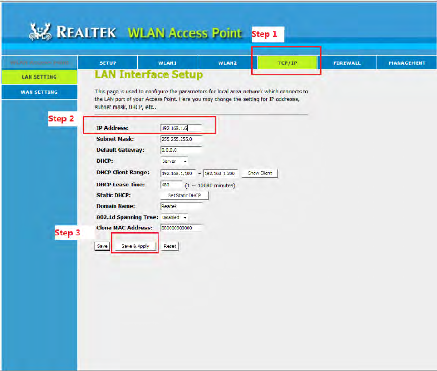
3.6 Change IP address
Bellow figure show how to change DUT IP address if you need to change it.
[End of file]
Federal Communication Commission Interference Statement
This equipment has been tested and found to comply with the limits for a Class B digital
device, pursuant to Part 15 of the FCC Rules. These limits are designed to provide
reasonable protection against harmful interference in a residential installation. This
equipment generates, uses and can radiate radio frequency energy and, if not installed
and used in accordance with the instructions, may cause harmful interference to radio
communications. However, there is no guarantee that interference will not occur in a
particular installation. If this equipment does cause harmful interference to radio or
television reception, which can be determined by turning the equipment off and on, the
user is encouraged to try to correct the interference by one of the following measures:
● Reorient or relocate the receiving antenna.
● Increase the separation between the equipment and receiver.
● Connect the equipment into an outlet on a circuit different from that to which the
receiver is connected.
● Consult the dealer or an experienced radio/TV technician for help.
FCC Caution: Any changes or modifications not expressly approved by the party
responsible for compliance could void the user’s authority to operate this equipment.
This device complies with Part 15 of the FCC Rules. Operation is subject to the following two
conditions: (1) This device may not cause harmful interference, and (2) this device must accept
any interference received, including interference that may cause undesired operation.
This device is restricted for indoor use.
IMPORTANT NOTE:
FCC Radiation Exposure Statement:
This equipment complies with FCC radiation exposure limits set forth for an uncontrolled
environment. This equipment should be installed and operated with minimum distance
20cm between the radiator & your body.