La Crosse Technology M-10 thermo-hygro sensor User Manual 14 TX62UTH IT manual
La Crosse Technology Ltd. thermo-hygro sensor 14 TX62UTH IT manual
UserManual.wiki
>
La Crosse Technology
>
M 10 User Manual
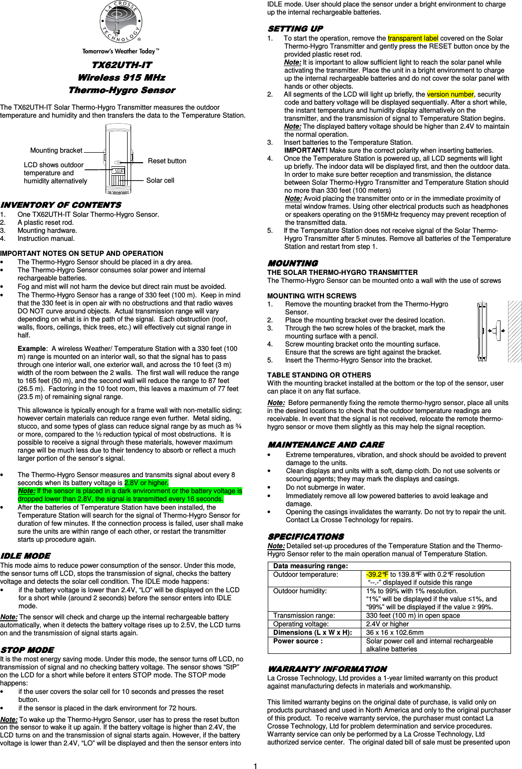
User's Manual
Navigation menu
Upload a User Manual
Namespaces
Wiki Guide
HTML
PDF
Info
Views
User Manual
Discussion / Help
Navigation