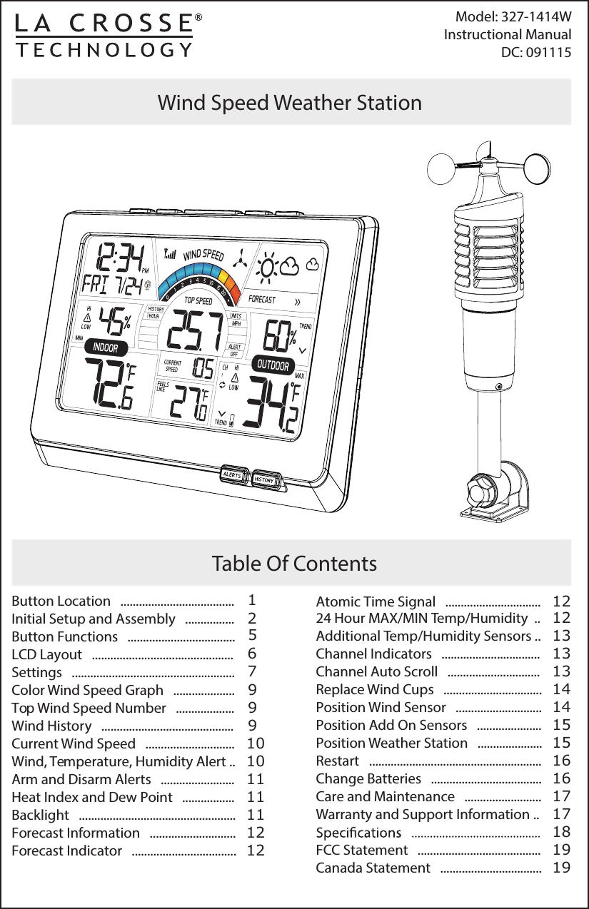
La Crosse Technology TX141W Wind Speed Weather Station User Manual

La Crosse Technology Ltd. Wind Speed Weather Station Users Manual

Users Manual

Model: 327-1414WInstructional  Manual  DC: 091115Table Of ContentsWind Speed Weather StationButton Location   .....................................                            Initial Setup and Assembly   ................Button Functions   ...................................LCD Layout   ..............................................Settings   .....................................................Color Wind Speed Graph   ....................Top Wind Speed Number   ...................Wind History   ...........................................Current Wind Speed   .............................Wind, Temperature, Humidity Alert ..Arm and Disarm Alerts   ........................Heat Index and Dew Point   .................Backlight   ...................................................Forecast Information   ............................Forecast Indicator   ..................................125679991010111111121224 Hour MAX/MIN Temp/Humidity  ..Additional Temp/Humidity Sensors ..Channel Indicators   ................................Channel Auto Scroll   ..............................Replace Wind Cups   ................................Position Wind Sensor   ............................Position Add On Sensors   .....................Position Weather Station   .....................Restart   ........................................................Change Batteries   ....................................Care and Maintenance   .........................Warranty and Support Information ..FCC Statement   ........................................Canada Statement   ................................. Atomic Time Signal   ............................... 12121313131414151616171718191519
Page | 1              www.lacrossetechnology.com/support             Model: 327-1414W Back ViewFront View1HistoryFront Buttons12AlertsButton Location21Heat/DewTop Buttons2UpLight(HI/LOW-OFF)3Time Set4Down551 234
Initial Setup and Assembly - TX141W SensorOutdoor SensorTX141WBattery Compartment3 “AAA” BatteriesBack ViewAAAAAAModel: 327-1414W        www.lacrossetechnology.com/support                  Page | 2AAACC1. Twist battery cover left to remove from sensor.Twist LeftPower the Weather Station:1. Insert AC adapter into the outlet     and into the weather station2. Insert three AAA batteries into    the weather station (optional).3. After 15 minutes, mount the sensor       outside (position Wind Sensor).AC/DC Adapter
CC   Page | 3      www.lacrossetechnology.com/support          Model:  327-1414W 2. Install two “C” batteries according to polarity.3. The red LED light will ash when transmitting.4. Replace the battery cover5. Insert pole into bottom of sensor and secure with two screws.Do not overtighten screwsTurn right totightenConnectConnectthe sensor to the baseScrews into designatedholesInsert screws on each sideof the sensor
Model:  327-1414W            www.lacrossetechnology.com/support              Page | 46. Align the square opening on the pole over the square of the mounting bracket.7. Turn the knob to tighten the bracket to the pole.   Note: You can attach to a dierent pole (1.2 inches, 3.1 cm diameter) into the                sensor, instead of using the mounting bracket.Screw until tight.Do not overtighten.Sensor Dimensions (Top View)Full Sensor and Bracket (with cup) Dimensions:18.57” T  x  7.10” W  x  7.10” D (inch dimensions) 4.67  6.74   1.23  2.84  3.54  6.08  2.88  2.42  2.32  18.57  1.43 7.10
ALERTS• Hold ALERTS button to enter    alerts settings•         or        to adjust value•  Press ALERTS to conrmALERT ACTIVATION•  Press ALERTS button to toggle    between alerts•  Press      to arm alerts•  Press      to disarm alerts   •  Press ALERTS to conrm  Page | 5               www.lacrossetechnology.com/support          Model:  327-1414W Button FunctionsLIGHTHI-LOW-OFF(Down)• Press to view channels• Hold to search for sensors• Will disarm alertTIME SET• Press to search for WWVB     Atomic time signal• Hold to enter setting modeLIGHT (HI-LOW-OFF):• Press to adjust backlight• Press to exit setting modeHEAT/DEW• Press to view Heat Index/Dew Point(UP)• Press to view MAX/MIN values• Hold to reset MAX/MIN values• Will arm alertHISTORY• Press to view top wind speed historyTop ButtonsFront ButtonsTIME SET HEAT/DEW UPDOWN
Model:  327-1414W          www.lacrossetechnology.com/support                   Page | 6ABCDEFGHSensor Reception Icon-Feels Like (Channel 1 only)Heat Index and Dew Point-Current Speed(30 second average)-Top Speed Reading (past 60 minutes)-Color Wind Speed Graph (based on current speed)-Wind Cup Icon(spins with wind speed)-Wind Speed Unit (MPH or KMH)Wind Speed Alert--ABCDEGHABCDEAtomic Time/DateAtomic Signal Icon--Indoor Humidity Alert Icon    HI and LOW- Indoor Humidity-Indoor Temperature-IIWind Speed HistoryLCD layoutABCDE-F
• Hold the TIME SET button to enter settings menu.• Move through settings with the TIME SET button. • The      and      buttons will adjust settings.• Exit at anytime with  the LIGHT button.  Settings:IABDEFGHCJ Forecast IconForecast Trend Indicator----Outdoor HumidityHumidity Trend Icon--Outdoor Temperature Channel IndicatorOutdoor Temperature HI/LO Alert Icon-Channel Scroll Indicator--Outdoor Temperature Trend Indicator-Low Battery IndicatorPage | 7                  www.lacrossetechnology.com/support              Model: 327-1414WABCDEFGHIJOutdoor Temperature
Page | 7                  www.lacrossetechnology.com/support              Model: 327-1414W Model: 327-1414W          www.lacrossetechnology.com/support                  Page | 81. Beep  ON (default) or OFF 2. Atomic  ON (default) or OFF3. Select  Time Zone (EST Default)CSTMSTTime ZoneAtlanticEasternCentralMountainPacicAlaskaHawaiianASTESTPSTAKTHAT4.  Select DST ON (default) or OFF5.  Choose 12 (default) or 24 hour time 6. Set Hours 7. Set Minutes8. Set  Year 9.  Set Month 10. Set Date12. Select Fahrenheit / Celsius11 Select  MPH or KMH  Note: When Atomic OFF is selected, steps 3 & 4 will not show and you           will automatically move to step 5.
Color Wind Speed GraphThe wind speed graph with color sections is based on current wind speed. One segment will ash indicating current wind speed. OrangeRedColor0 - 1415 - 1920 - 24over 25BlueYellowSpeedThe wind cup icon will spin at varying speeds according to the current speed.  Top Wind Speed NumberWind Cup Icon   Page | 9             www.lacrossetechnology.com/support              Model: 327- 1414WPress and release the HISTORY button to view the past top wind speeds with time and date of occurrence. The 1 hour top speed is the default reading shown on the display. Wind HistoryCOLOR WIND SPEED ICON• Highest instantaneous wind speed recorded in the past 60 minutes.  • Updates when a higher wind speed has occurred.  • Last number will remain if there is no wind for 60 minutes.• 24-hour: Past 24 hour period, from last record.• Week: Past 7-day period, from last record.• Month: Dened by Calendar Month   i.e.  January 1 - January 31.• Year: Dened by Calendar Year    i.e. January 1 - December 31.
Setting alert value and arming individual alerts are separate functions.Set alert value:1. Hold the ALERTS button for 3 seconds to enter alert set mode. 2. The high wind speed alert value will blink in set mode. 3. Press the         or         buttons to adjust the values.4. Press the ALERTS button to conrm and move to the next alert.The alert setting order: • High Wind Speed (channel 1 only)• Outdoor Humidity HI• Outdoor Humidity LOW• Outdoor Temperature HI• Outdoor Temperature LOW• Indoor Humidity HI• Indoor Humidity LOW• Indoor Temperature HI• Indoor Temperature LOW    Note: When using multiple temperature/humidity sensors, press the       button                to select the channel (1, 2, or 3) before setting alerts for a sensor.  Model: 327-1414W               www.lacrossetechnology.com/support             Page | 10Wind, Temperature & Humidity AlertsOutdoor HI TemperatureIndoor LOW HumidityWind Speed High Alert Outdoor HI HumidityOutdoor LOW TemperatureIndoor HI TemperatureOutdoor LOW HumidityIndoor LOW TemperatureIndoor HI HumidityCurrent Wind SpeedThe current wind speed which represents a 30 second average of wind speed samples taken. This should correspond to the wind graph above.
Press the HEAT/DEW button repeatedly to toggle between:Page | 11            www.lacrossetechnology.com/support              Model: 327-1414WArm/Disarm Alerts:1. Press and release the ALERTS button to select an alert. HI and LO will ash.2. Press the        button to arm the alert. 3. Press the        button to disarm the alert. 4. The HI or LO alert icon appears when armed.                                 Active Alert: Beeps once per minute with ashing alert icon.Feels Like Temperature, Heat Index, Dew Point TemperatureHeat Index (outdoor)Note: Feels Like Temperature is the perceived outdoor temperature. • Temperatures below 50°F, will measure the eect of wind speed on cooling      of the human body.• Temperatures above 70°F, will measure the eect of humidity on the      perception of temperature. • Between 51 °F and 69°F, the feels like temperature will be the same as the     outdoor temperature on channel 1.Feels Like Temperature (Channel 1 only)Default (always displayed)Dew Point (outdoor)Backlight AdjustmentsUse AC power for constant backlight: • Press the LIGHT button on the top of the     weather station to adjust the backlight     (HI-LOW-OFF) when using AC power. When using battery power only: • Press the LIGHT button for a 10 second     backlight (It will not stay on).
Model: 327-1414W           www.lacrossetechnology.com/support                 Page | 12Forecast InformationIntelligent Weather Forecast:    Note: Snowy icon will appear in place of rainy and stormy icons when the                outdoor temperature (Channel 1) is below 32°F.Sunny Partly Sunny CloudyRainy Stormy SnowyThe station automatically resets MAX and MIN values daily at midnight (12:00 AM). • Press the      button once to view MAX indoor/outdoor temperatures.   • Then, hold the      button to manually reset MAX temperatures to current values. • Press the      button again to view the MIN indoor/outdoor temperatures.• Then, hold the      button to manually reset MIN temperatures to current values. Forecast Tendency Indicators (Up, Right and Down Arrows)24 hour MAX/MIN Temperature/Humidity recordsRising PressureSteadyPressureFallingPressureWeather is expected to improveWeather is expected to stay the sameWeather is expected to worsenAtomic Icon• When WWVB is on, press and release the TIME SET button to start or stop a  WWVB signal   search.• WWVB Icon will ash when searching.For information about WWVB, visit: www.nist.gov/pml/div688/grp40/wwvb.cfm  Atomic Time SignalThis station learns: Please allow 7-10 days for barometric calibration. This will ensure an accurate personal forecast for your location.Six animated forecast icons use changing atmospheric pressure to predict weather conditions for the next 12-hours with 70-75% accuracy.
The wind station will accommodate up to two additional thermohygro sensors (TX141TH-BCH ) on channels 2 and 3.    Note: The TX141W sensor must be on channel 1.Press the     button to view sensors on other channels.Setup additional sensors to the wind station:  1. Remove the battery cover from all the sensors        (leave battery covers o until all sensors are received        by the wind station).  2. Set the rst additional sensor to Channel 2 and insert       2 AA batteries.   3. Set the second additional sensor to Channel 3 and insert       2 AA batteries.  4. Hold the      button on the wind station for 5 seconds to       search for sensors.  5. Press the TX button on each sensor.  6. When connection is established, the temperature &       humidity for each of the selected channels will appear.   7. Install the battery covers on each sensor.  8. Keep sensors and the wind station 5-10 feet apart for 15       minutes to establish a solid connection.   9. After 15 minutes, place the remote sensors in appropriate        shaded locations.10. Press and release the      button to view channels 1, 2 or 3 on       the wind station when multiple sensors are used.    Note: If only one sensor is connected, the other channels will                show dashes for  temperature and humidity.  Page | 13             www.lacrossetechnology.com/support            Model: 327-1414WSetup Add On Temperature/Humidity SensorsChannel Indicator• Press the      button to toggle between remote sensor channels when multiple       sensors are used.Channel Auto Scroll• The wind station will automatically rotate through the channels for all    connected sensors.  • Press and release the      button to lock the wind station into one channel.• Then press the      button to view channels individually.AA1    2    3AAAAAA
• For the most accurate wind speed readings, mount the TX141W sensor as the      highest object for 50 feet in all directions. • Cups should be on the top of the sensor. Mount vertically.• The maximum wireless transmission range to the wind station is over 300 feet      (91 meters) in open air, not including walls or trees.1. Insert mounting pole into sensor.2. Tighten screws3. Insert bottom of pole into mounting bracket4. Tighten knob to secure5. Use screws through the bottom of the    mounting bracket to attach.6. The sensor can be mounted from     the bottom or side. (the picture is     of the sensor mounted from the side)Alternatively:1. Insert your own mounting pole into     the sensor.2. Tighten screws3. Mounting bracket would not be used.    Note: Do not attempt to insert a pole into the hollow back of the mounting bracket. Model: 327-1414W                www.lacrossetechnology.com/support            Page | 14Replace Wind Cups1. Loosen the screw2. Remove cups3. Install new cups4. Tighten screwNote: The screw in the wind cups will t on the at side of the metal stem on the sensor.Position Wind SensorFlat Side Of  Stem UpInsert and AttatchFlat End up
  Page | 15                www.lacrossetechnology.com/support         Model: 327-1414WPosition Add On Sensors• Mount the outdoor sensor on a north-facing wall or in any well shaded area.      Under an eave or deck rail is preferred. • The maximum wireless transmission range to the weather station is over 300     feet (91 meters) in open air, not including walls or oors.• Be sure the outdoor sensor is mounted verticallyOption 1:• Install one mounting screw into a wall leaving some extended.• Place the transmitter onto the screw.• Gently pull the transmitter down to lock the screw into place. Option 2:   • Insert the mounting screw through the front of the transmitter and into the wall. • Tighten the screw to snug (do not over tighten).Position Weather Station• Pull out the stand and place on a at surface.• Use the three hanging holes on the back to mount on the wall.  1. Choose a location 6 feet or more away from electronics such as cordless        phones, gaming systems, televisions, microwaves, routers, etc.2. Place within range of the outdoor sensors (300 ft, 91 meters open air). 3. Obstacles such as walls, windows, stucco, concrete, and large metal objects     can reduce the range.4. For best WWVB reception, orientate the weather station with the front or back    of the  station facing Ft. Collins, Colorado.Mount sensor on a north-facing wall(under an eave or deck rail is preferred)ROOFWALLNote: Mount 18’ below the eave to avoid venting from your attic causing inaccurate readings.
Add on Sensor(s):1. Slide battery cover down and lift o sensor.2. Remove old batteries and install fresh “AA” batteries.3. Hold the      button on the weather station for 5 seconds to search for the sensor.TX141W Sensor mounted:1. Grab the vented portion of the sensor and turn counter clockwise.2. Remove old batteries and install fresh “C” batteries.3. Carefully align and turn clockwise to tighten.4. Hold the       button on the weather station for 5 seconds to search for     the sensor.Restart 1. Remove batteries from the sensor and batteries and AC adapter from the     weather station. 2. Press any button 20 times. 3. After 15 minutes insert batteries into the sensor, then insert batteries (optional        in the weather station) and plug AC adapter into the weather station. 4. Wait 15 minutes to establish a strong connection. Place sensor outside.Change BatteriesModel: 327-1414W              www.lacrossetechnology.com/support               Page | 16CCPress the Down  Button on the wind station to search for sensorsTX141W Sensor Add-On SensorAA1    2    3AAAAAA
Care and Maintenance• Do not mix old and new batteries• Do not mix Alkaline, Standard, Lithium or Rechargeable Batteries• Always purchase the correct size and grade of battery most suitable for    the intended use.• Replace all batteries of a set at the same time.• Clean the battery contacts and also those of the device prior to    battery installation.• Ensure the batteries are installed correctly with regard to polarity (+ and -).• Remove batteries from equipment which is not to be used for an    extended period of time.• Remove expired batteries promptly.• Do not expose to extreme temperature, vibration or shock. • Clean with a soft damp cloth. Do not use solvents or scouring agents.• The product is not a toy. Keep it out of reach of children.• The product is not to be used for medical purpose or for public information.     It is intended for home use only.• The specs of this product may change without prior notice.• Improper use or unauthorized opening of housing voids warranty.• If the product is not working properly, change the batteries and/or check    the AC adapter connection.La Crosse Technology, Ltd. provides a 1-year limited time warranty (from date of purchase) on this product relating to manufacturing defects in materials & workmanship. Before returning a product, please contact our friendly customer support with questions or visit our online help (FAQS):Phone: 1-608-782-1610   Online Product Support: www.lacrossetechnology.com/support  Product Registration:  www.lacrossetechnology.com/support/register    View full warranty details online at:   www.lacrossetechnology.com/warranty_info.pdf Warranty Address:              Protected under U.S. Patents:La Crosse Technology, Ltd            5,978,738 | 6,076,044 | RE439032830 S. 26th St.La Crosse, WI 54601Warranty and Support Information  Page | 17             www.lacrossetechnology.com/support           Model: 327-1414W
Indoor• Temperature Range: 32°F to 122°F (0°C to 50°C)• Humidity Range: 10% - 99% (RH)Outdoor• Temperature Range:  -40°F to 140°F (-40°C to 60°C)• Humidity Range: 10% - 99% (RH)• Wind Speed Range: 0 - 99 mph (0-159 kMh)Power• Wind Station Primary AC Power:   5-volt AC power adapter (included in lower panel)• AC Adapter NO.:   GPU280500150WD00 5VDC 150mA• Optional/Battery Backup:   3-AAA, IEC, LR3 batteries (not included)BatteryLife• Wind/TH Sensor:   2-C, IEC, LR14 batteries (not included)• Wind Station Battery Backup:   Battery life is over 12 months when using the AC adapter  for primary powerDimensions• Wind Station: 5.48” H x 8.34” L  x 1.03” W   (139.19 x 211.84 x 26.12 mm)• TX141W Sensor: 18.57” H  x  7.10” W  x  7.10” D( 471.68 x 180.34 x 180.34 mm)SpecicationsModel: 327-1414W          www.lacrossetechnology.com/support               Page | 18• Wind/TH Sensor:   Battery life is over 24 months when using reputable  battery brands• Interval: about every 30 seconds• Distance: Over 300ft. (91 meters) RF 433MHz (open air)
FCC Statement Caution!   Page | 19          www.lacrossetechnology.com/support            Model: 327-1414W  This equipment has been tested and found to comply with the limits for a Class B digital device, pursuant to part 15 of the FCC Rules. These limits are designed to provide reasonable protection against harmful interference in a residential installation. This equipment generates, uses and can radiate radio frequency energy and, if not installed and used in accordance with the instructions, may cause harmful interference to radio communications. However, there is no guarantee that interference will not occur in a particular installation. If this equipment does cause harmful interference to radio or television reception, which can be determined by turning the equipment o and on, the user is encouraged to try to correct the interfer-ence by one or more of the following measures:       • Reorient or relocate the receiving antenna.      • Increase the separation between the equipment and receiver.       • Connect the equipment into an outlet on a circuit dierent from that to                 which the receiver is connected.       • Consult the dealer or an experienced radio/TV technician for help.The FCC statement is found inside the battery compartment.        This device must not be co-located or operating in conjunction with any other antenna or transmitter. Operation is subject to the following two conditions: (1) this device may not cause harmful interference, and (2) this device must accept any interference received, including interference that may cause undesired operation.The manufacturer is not responsible for any radio or TV interference caused by unauthorized changes or modications to this equipment. Such changes or modications could void the user authority to operate the equipment.All rights reserved. This manual may not be reproduced in any form, even in part, or duplicated or pro-cessed using electronic, mechanical or chemical process without the written permission of the publisher.This booklet may contain errors or misprints. The information it contains is regularly checked and corrections are included in subsequent editions. We disclaim any responsibility for any technical error or printing error, or their consequences.All trademarks and patents are recognized.Canada Statement This device complies with Industry Canada’s licence-exempt RSSs. Operation is subject to the following two conditions: (1) This device may not cause interference; and (2) This device must accept any interference, including interference that may cause undesired operation of the device. Le présent appareil est conforme aux CNR d’Industrie Canada applicables aux appareils radio exempts de licence. L’exploitation est autorisée aux deux conditions suivantes : (1) l’appareil ne doit pas produire de brouillage; (2) l’utilisateur de l’appareil doit accepter tout brouillage radioélectrique subi, même si le brouillage est susceptible d’en compromettre le fonctionnement.

Navigation menu