Laird Connectivity 2510100 2.4Ghz Frequency Hopping Spread Spectrum transceiver User Manual LT2510 Users Manual
AeroComm Corporation 2.4Ghz Frequency Hopping Spread Spectrum transceiver LT2510 Users Manual
UserManual.wiki
>
Laird Connectivity
>
2510100 User Manual
User Manual
Navigation menu
Upload a User Manual
Namespaces
Wiki Guide
HTML
PDF
Info
Views
User Manual
Discussion / Help
Navigation
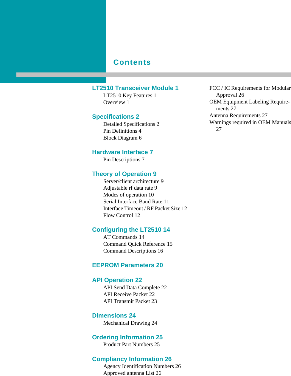

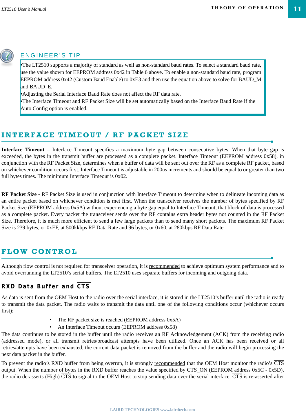
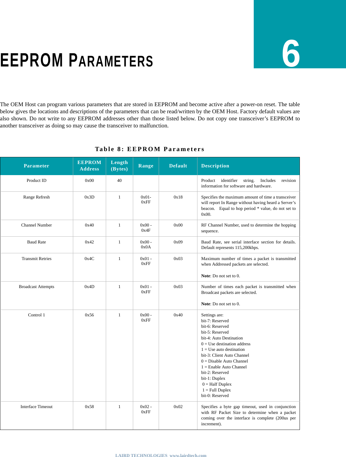
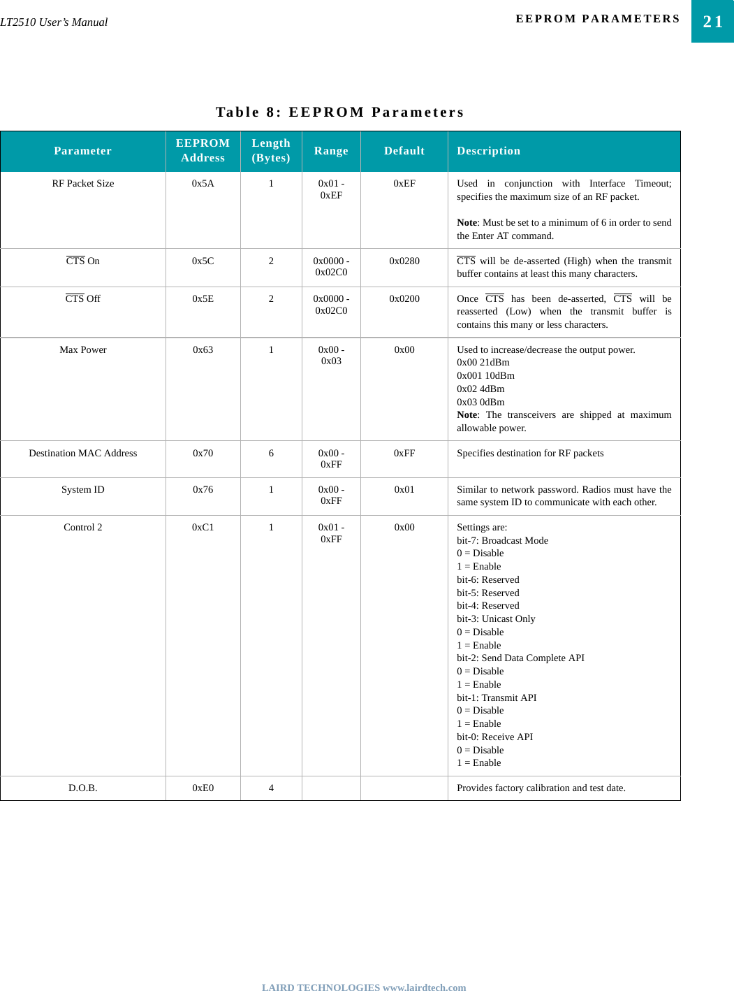
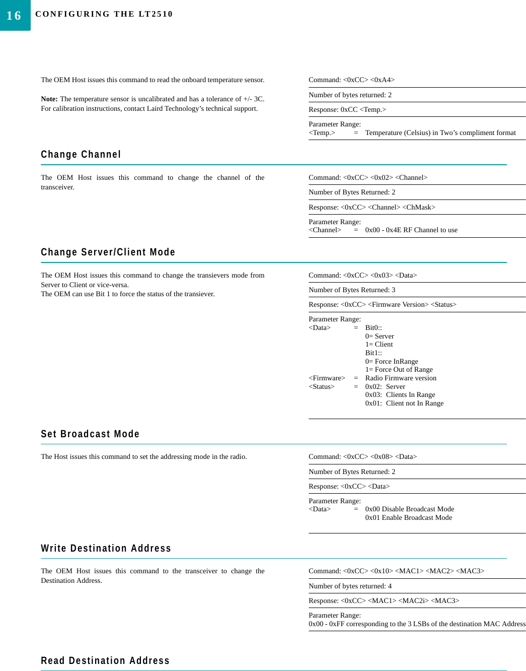
![LAIRD TECHNOLOGIES www.lairdtech.comEEPROM Configuration CommandsTwo Commands are available to read and write the EEPROM of the radio. These commands are very powerful as they can controlthe entire configuration of the radio. They should be used with caution as overwriting reserved areas of memory can adverselyaffect the operation of the radio. The radio must be reset for any changes to the EEPROM to take affect.COMMAND QUICK REFERENCETable 4 provides an at-a-glance view of all available AT commands..Table 7: Command Quick ReferenceCommand Name Command (All bytes in Hex) Return (All bytes in Hex)Utility CommandsEnter AT Command Mode <0x41> <0x54> <0x2B> <0x2B> <0x2B> <0x0D> <0xCC> <0x43> <0x4F> <0x4D>Exit AT Command Mode <0xCC> <0x41> <0x54> <0x4F> <0x0D> <0xCC> <0x44> <0x41> <0x54>Enter Deep Sleep <0xCC> <0x86> <0x03> NoneSoft Reset <0xCC> <0xFF> NoneStatus CommandsStatus Request <0xCC> <0x00> <0x00> <0xCC> <Firmware Version> <Status>Read Temperature <0xCC> <0xA4> <0xCC> <Temperature>On-the-Fly CommandsChange Channel <0xCC> <0x02> <Channel> <0xCC> <Channel> Change Server/Client Mode <0xCC> <0x03> <Data> <0xCC> <Firmware Version> <Status>Set Broadcast Mode <0xCC> <0x08> <Data> <0xCC> <Data>Write Destination Address <0xCC> <0x10> <Dest Address last thee bytes> <0xCC> <Dest Addr>Read Destination Address <0xCC> <0x11> <0xCC> <Dest Addr> Auto Destination/Channel <0xCC> <0x15> <Data> <0xCC> <Data>Read API Control <0xCC> <0x16> <0xCC> <API Control>Write API Control <0xCC> <0x17> <API Control> <0xCC> <API Control>Read Digital Input <0xCC> <0x20> <0xCC> <Data>Read ADC <0xCC> <0x21> <Data> <0xCC> <ADC Hi> <ADC Lo>Write PWM Output <0xCC> <0x24> <Data> <0xCC> <0x24>Write Digital Outputs <0xCC> <0x23> <Data> <0xCC> <0x23>Set Power Control <0xCC> <0x25> <Power> <0xCC> <Power>EEPROM CommandsEEPROM Byte Read <0xCC> <0xC0> <Start> <Length> <0xCC> <Start> <Length> <Data [n-0]>EEPROM Byte Write <0xCC> <0xC1> <Start> <Length> <Data> <Start> <Length> <Last byte written>](https://usermanual.wiki/Laird-Connectivity/2510100/User-Guide-1079524-Page-20.png)
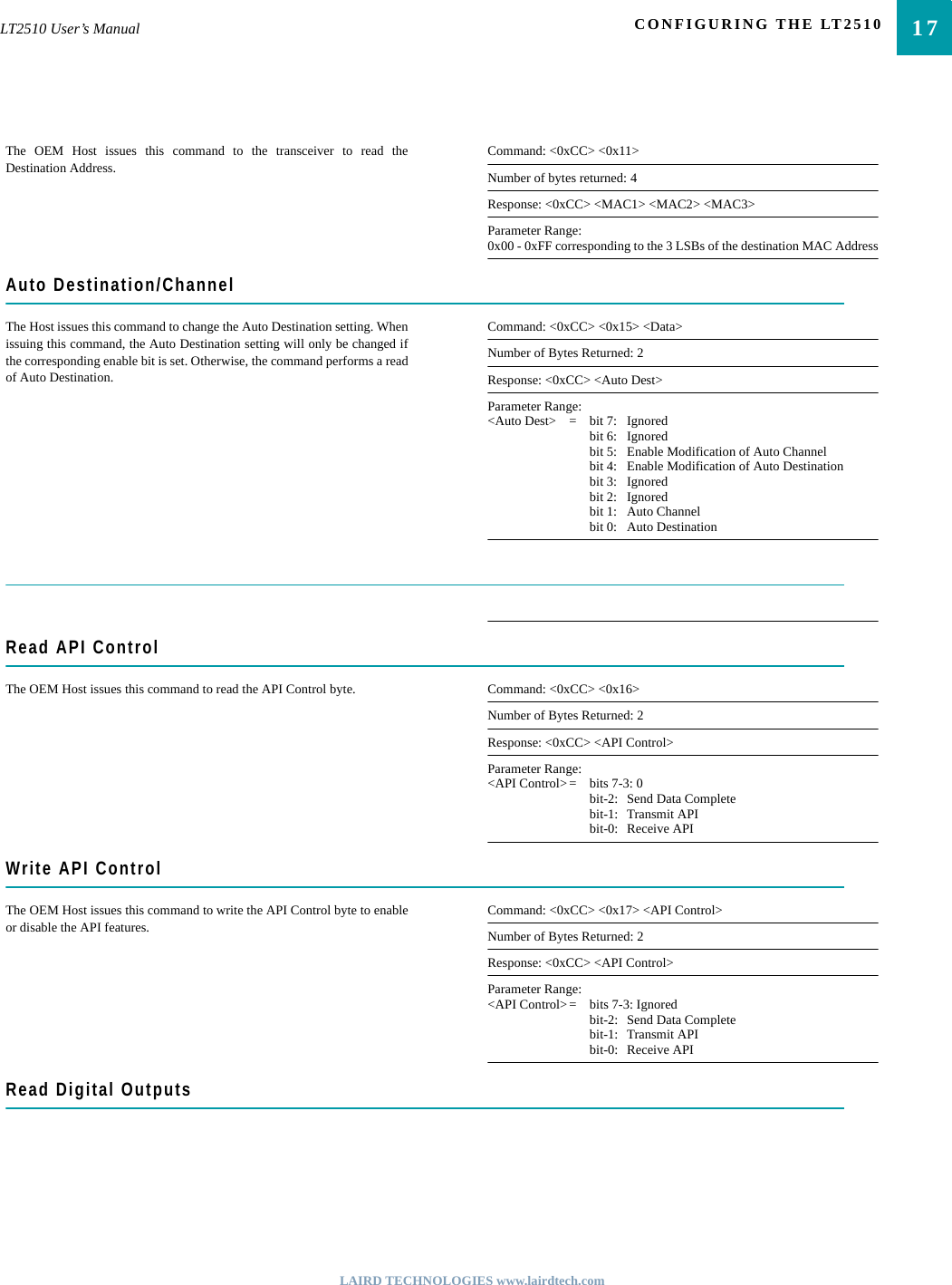
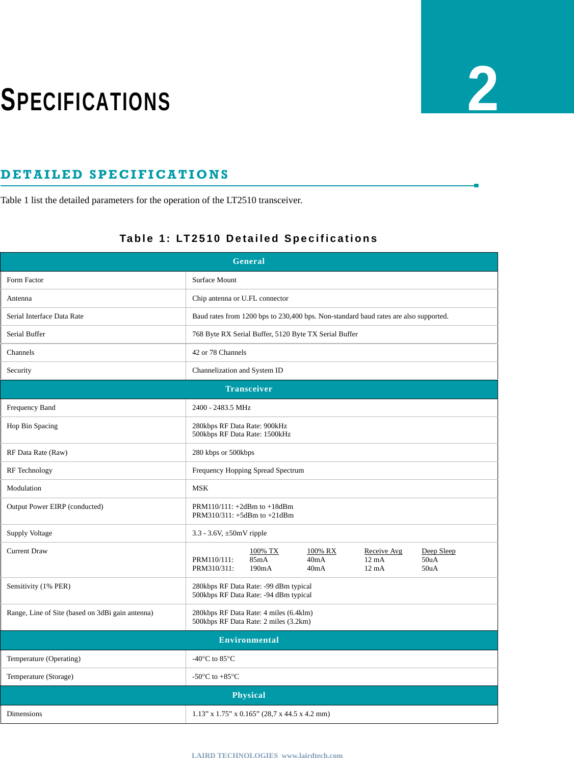
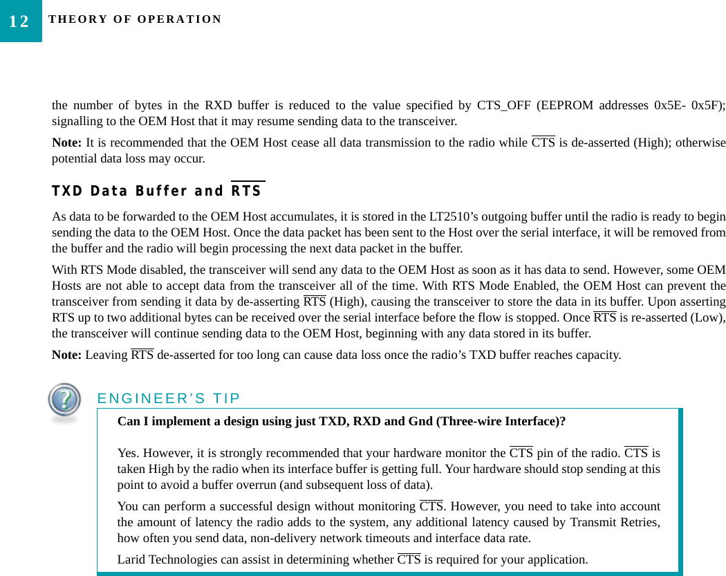
![CONFIGURING THE LT251018The OEM Host issues this command to read the state of both digital outputlines.Command: <0xCC> <0x20>Number of Bytes Returned: 2Response: 0xCC <Digital Out>Parameter Range:<Digital Out> = bit-1: GO1bit-0: GO0Read ADCThe OEM host issues this command to read the analog to digital convertersat up to 12-bit resolution. Higher resolutions can cause slower responsesfrom the command. The time required for a conversion is Tconv = (decimation rate + 16) * .23uS. In the most common forms this will be used to measure theinput voltage (todetect reduced battery power) with Vdd/3, the temperature sensor or theAnalog input on Pin 22. For the most accurate results the 1.25V internalreference should be chosen, though this would limit the OEM to a maximumAD/In of 1.25 v [Vdd/3 and Temperature Sensor should always be below1.25v]The ADC result is represented in a two’s complement form. The result isthe difference between ground and the selected channel and will be a valuebetween -2048 and 2047 with 2047 representing the maximum value wherethe ADC result equals the reference voltage and -2048 equals the negative ofthe reference voltage. The ADC cannot measure a voltage higher than thereference voltage.Command: <0xCC> <0x21> <Data>Number of Bytes Returned: 3Response: 0xCC <Hi ADC> <Lo ADC>Parameter Range:<Data bits 6-7>= <Reference Voltage>00: Internal 1.25V reference10: Vdd on AVdd pin<Data bits 4-5>= <Resolution>00: 64 decimation rate (7 bits resolution)01: 128 decimation rate (9 bits resolution)10: 256 decimation rate (10 bits resolution)11: 512 decimation rate (12 bits resolution)<Data bits 0-3>= <Channel>0000: AD/In PIn 221100: GND1101: Positive Voltage Reference1110: Temperature Sensor1111: Vdd/3<Hi ADC> = MSB or requested 12-bit ADC value<Lo ADC> = LSB of reequested 12-bit ADC valueWrite PWM OutputsThe OEM Host issues this command to set the PWM_Output. The PWMoutput is a repeating 630.1uS period. The PWM ratio is the ratio of the highpulse time to the low pulse time. A value of 0x00 will output a continuouslow signal. A ratio of 0xFF will output a continuous high signal. A ratio of0x80 will put out a repeating pulse of 315.05uS high and 315.05uS low.Command: <0xCC> <0x24> <PWM Ratio>Number of Bytes Returned: 2Response: 0xCC <0x24>Parameter Range:<PWM Ratio> = 0x00 -0xFF, the ratio of the high pulse versus the lowpulse for a single period. Write Digital OutputsThe OEM Host issues this command to write both digital output lines toparticular states.Command: <0xCC> <0x23> <Digital Out>Number of Bytes Returned: 2Response: 0xCC <0x23>Parameter Range:<Digital Out> = bit-1: GO1bit-0: GO0Set Max Power](https://usermanual.wiki/Laird-Connectivity/2510100/User-Guide-1079524-Page-24.png)
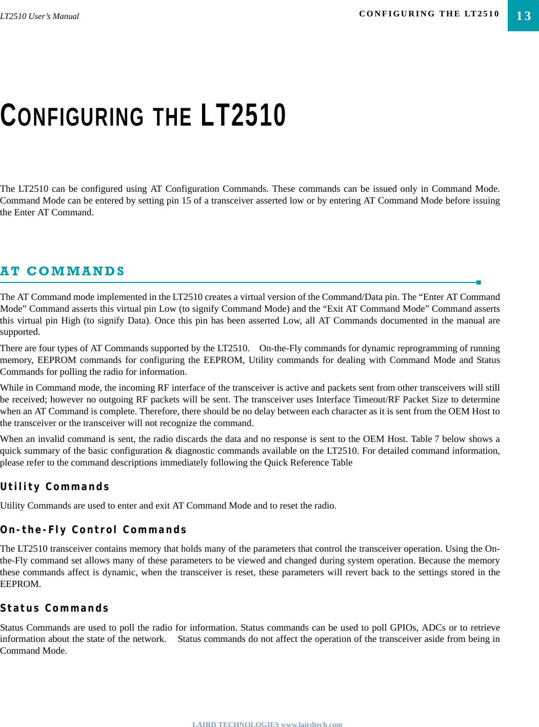
![19LT2510 User’s Manual CONFIGURING THE LT2510LAIRD TECHNOLOGIES www.lairdtech.comThe OEM Host issues this command to adjust the maximum output power. Command: <0xCC> <0x25> <Max Pwr>Number of Bytes Returned: 2Response: 0xCC <Max Pwr>Parameter Range:<Max Pwr> = Power0x00: 21 dBm0x01: 15 dBm0x02: 9 dBm0x03: 3 dBmEEPROM Byte ReadUpon receiving this command, a transceiver will respond with the desireddata from the addresses requested by the OEM Host.Command: <0xCC> <0xC0> <Start> <Length>Number of Bytes Returned: 4+Response: <0xCC> <Start> <Length> <Data>Parameter Range:<Start> = EEPROM address to begin reading at<Length> = Length of data to be read<Data> = Requested dataEEPROM Byte WriteUpon receiving this command, a transceiver will write the data byte to thespecified address but will not echo it back to the OEM Host until theEEPROM write cycle is complete.Note: The maximum length of data that can be written in a single writeprocess is 0x50. If writing the entire 256-byte EEPROM, it is convenient toperform 64 byte (0x40) writes.Command: <0xCC> <0xC1> <Start> <Length> <Data>Number of Bytes Returned: 3Response: <Start> <Length> <Last byte>Parameter Range:<Start> = EEPROM address to begin writing at<Length> = Length of data to be written (Max = 0x50)<Data> = Data to be written<Last byte> = Value of last byte writtenBin AnalyzerThe Bin Analyzer is a powerful command for understanding the linkconditions between two radios over the entire frequency hopping spectrum.The Bin Analyzer will cause the local radio to send a special Bin Analyzerpacket to the radio in the Desitnation field. The remote radio will respondwith RSSI information and this is then streamed to the OEM through theSerial UART. Due to the random frequency hopping sequence of the radios, it is notpossible to associate a specific bin # with a specific frequency, though theOEM can use the Bin Analyzer response to identify any possible interferersand to provide a quantitative analysis of the total number of good versusbad bins.The Bin Analyzer command will stream data results back for each hop untilthe command is turned off or the number of runs is met.The Bin Analyzer command must be issued from Command Mode, but itwill continue to stream results back even after the OEM has exitedCommand Mode. The Bin Analyzer packet is sent as part of the RF PacketHeader and does not affect the throughput of data between two radios.Command: <0xCC> <0x8F> <Control> <NumRuns>Number of Bytes Returned: 2Response: <0xCC> <0x8F> Bin Response Stream: <0xCC> <Bin#> <RSSI_1> <RSSI_2>Parameter Range:<Control> = 0x00= Turn Bin Analyzer Off0x01= Turn Bin Analyzer On<NumRuns> = 0x00= Continous0x01- 0xFF= Number of runs [bins]<Bin#> = Bin# from 0-79 or 0-53 depending on the RF DataRate<RSSI_1> = RSSI the remote radio heard the local radio’s binrequest<RSSI_2> = RSSI the local radio heard the remote radio’s response](https://usermanual.wiki/Laird-Connectivity/2510100/User-Guide-1079524-Page-25.png)