Laird Connectivity 2510100 2.4Ghz Frequency Hopping Spread Spectrum transceiver User Manual LT2510 Users Manual
AeroComm Corporation 2.4Ghz Frequency Hopping Spread Spectrum transceiver LT2510 Users Manual
User Manual

LT2510 User Manual
version 1.0.8
Technical Support: Phone: 800.492.2320
E-mail: wireless.support@lairdtech.com
Web: www.lairdtech.com/wireless
Sales: Phone: 800.492.2320
E-mail: WirelessInfo@lairdtech.com
Web: www.lairdtech.com

Document Information
Copyright © 2008 Laid Technologies, Inc. All rights reserved.
The information contained in this manual and the accompanying software programs are copyrighted and all rights are reserved by
Laird Technologies, Inc. Laird Technologies, Inc. reserves the right to make periodic modifications of this product without
obligation to notify any person or entity of such revision. Copying, duplicating, selling, or otherwise distributing any part of this
product or accompanying documentation/software without the prior consent of an authorized representative of Laird Technologies,
Inc. is strictly prohibited.
All brands and product names in this publication are registered trademarks or trademarks of their respective holders.
This material is preliminary
Information furnished by Laird Technologies in this specification is believed to be accurate. Devices sold by Laird Technologies
are covered by the warranty and patent indemnification provisions appearing in its Terms of Sale only. Laird Technologies makes
no warranty, express, statutory, and implied or by description, regarding the information set forth herein. Laird Technologies
reserves the right to change specifications at any time and without notice.
Laird Technologies’ products are intended for use in normal commercial and industrial applications. Applications requiring
unusual environmental requirements such as military, medical life-support or life-sustaining equipment are specifically not
recommended without additional testing for such application.
Limited Warranty, Disclaimer, Limitation of Liability
For a period of one (1) year from the date of purchase by the OEM customer, Laird Technologies warrants the OEM transceiver
against defects in materials and workmanship. Laird Technologies will not honor this warranty (and this warranty will be
automatically void) if there has been any (1) tampering, signs of tampering; 2) repair or attempt to repair by anyone other than an
Laird Technologies authorized technician.
This warranty does not cover and Laird Technologies will not be liable for, any damage or failure caused by misuse, abuse, acts of
God, accidents, electrical irregularity, or other causes beyond Laird Technologies’ control, or claim by other than the original
purchaser.
In no event shall Laird Technologies be responsible or liable for any damages arising: From the use of product; From the loss of
use, revenue or profit of the product; or As a result of any event, circumstance, action, or abuse beyond the control of Laird
Technologies, whether such damages be direct, indirect, consequential, special or otherwise and whether such damages are
incurred by the person to whom this warranty extends or third party.
If, after inspection, Laird Technologies’ determines that there is a defect, Laird Technologies will repair or replace the OEM
transceiver at their discretion. If the product is replaced, it may be a new or refurbished product.

Revision History
Revision Description
Version 1.0 7/21/08 - Initial Release Version
Version 1.0.1 8/25/08- Updated name to LT2510
Version 1.0.2 10/8/08- Changed Modulation and RF Data Rate
Version 1.0.3 11/17/08- Added TX API and Adjustable RF Data Rate
Version 1.0.4 12/4/08- Engineering Updates
Version 1.0.5 1/27/09- Updated FCC/IC IDs and Antenna information
Version 1.0.6 2/11/09- Updated Read ADC, Write PWM and FCC Warnings, Added
Bin Analyzer and Change Server/Client Mode Commands
Version 1.0.7 2/23/2009- Updated Antenna requirements for FCC approval
Version 1.0.8 3/10/09- Portable and Mobile qualifications for FCC approval

Contents
LT2510 Transceiver Module 1
LT2510 Key Features 1
Overview 1
Specifications 2
Detailed Specifications 2
Pin Definitions 4
Block Diagram 6
Hardware Interface 7
Pin Descriptions 7
Theory of Operation 9
Server/client architecture 9
Adjustable rf data rate 9
Modes of operation 10
Serial Interface Baud Rate 11
Interface Timeout / RF Packet Size 12
Flow Control 12
Configuring the LT2510 14
AT Commands 14
Command Quick Reference 15
Command Descriptions 16
EEPROM Parameters 20
API Operation 22
API Send Data Complete 22
API Receive Packet 22
API Transmit Packet 23
Dimensions 24
Mechanical Drawing 24
Ordering Information 25
Product Part Numbers 25
Compliancy Information 26
Agency Identification Numbers 26
Approved antenna List 26
FCC / IC Requirements for Modular
Approval 26
OEM Equipment Labeling Require-
ments 27
Antenna Requirements 27
Warnings required in OEM Manuals
27

LAIRD TECHNOLOGIES www.lairdtech.com
LT2510 T
RANSCEIVER
M
ODULE
1
The LT2510 Frequency Hopping Spread Spectrum Transceiver Module from Laird Technology is the latest in robust and easy to
use radio modules. Supporting both high data rates and long ranges, the LT2510 is a great fit for any number of machine-to-
machine applications. The LT2510 features an easy to use serial UART with hardware flow control for fast integration into an
existing serial infrastructure.
LT2510 KEY FEATURES
• Retries and Acknowledgements
• Programmable Network Parameters
• Multiple generic I/O
• 280 kbps or 500kbps RF data stream
• Receive Average current draw of 12mA
• Software selectable interface baud rates from 1200 bps to 230.4 kbps
• Low cost, low power and small size ideal for high volume, portable and battery powered applications
• All modules are qualified for Industrial temperatures (-40°C to 85°C)
• Advanced configuration available using AT commands
• Easy to use Configuration & Test Utility software
OVERVIEW
This document contains information about the hardware and software interface between a Laird Technologies LT2510 transceiver
and an OEM Host. Information includes the theory of operation, specifications, interface definitions, configuration information
and mechanical drawings.
Note: Unless mentioned specifically by name, the LT2510 modules will be referred to as “radio” or “transceiver”. Individual
naming is used to differentiate product specific features. The host (PC/Microcontroller/Any device to which the LT2510 module is
connected) will be referred to as “OEM Host” or “Host.”

LAIRD TECHNOLOGIES www.lairdtech.com
S
PECIFICATIONS
2
DETAILED SPECIFICATIONS
Table 1 list the detailed parameters for the operation of the LT2510 transceiver.
Table 1: LT2510 Detailed Specifications
General
Form Factor Surface Mount
Antenna Chip antenna or U.FL connector
Serial Interface Data Rate Baud rates from 1200 bps to 230,400 bps. Non-standard baud rates are also supported.
Serial Buffer 768 Byte RX Serial Buffer, 5120 Byte TX Serial Buffer
Channels 42 or 78 Channels
Security Channelization and System ID
Transceiver
Frequency Band 2400 - 2483.5 MHz
Hop Bin Spacing 280kbps RF Data Rate: 900kHz
500kbps RF Data Rate: 1500kHz
RF Data Rate (Raw) 280 kbps or 500kbps
RF Technology Frequency Hopping Spread Spectrum
Modulation MSK
Output Power EIRP (conducted) PRM110/111: +2dBm to +18dBm
PRM310/311: +5dBm to +21dBm
Supply Voltage 3.3 - 3.6V, ±50mV ripple
Current Draw 100% TX 100% RX Receive Avg Deep Sleep
PRM110/111: 85mA 40mA 12 mA 50uA
PRM310/311: 190mA 40mA 12 mA 50uA
Sensitivity (1% PER) 280kbps RF Data Rate: -99 dBm typical
500kbps RF Data Rate: -94 dBm typical
Range, Line of Site (based on 3dBi gain antenna) 280kbps RF Data Rate: 4 miles (6.4klm)
500kbps RF Data Rate: 2 miles (3.2km)
Environmental
Temperature (Operating) -40°C to 85°C
Temperature (Storage) -50°C to +85°C
Physical
Dimensions 1.13” x 1.75” x 0.165” (28,7 x 44.5 x 4.2 mm)

3
LT2510 User’s Manual SPECIFICATIONS
LAIRD TECHNOLOGIES www.lairdtech.com
PIN DEFINITIONS
The LT2510 has a simple interface that allows OEM Host communications with the transceiver. Table 2 below shows the
connector pin numbers and associated functions.
Certifications
FCC Part 15.247 KQL-2510100
Industry Canada (IC) 2268C-2510100
CE Pending
Table 2: Pin Definitions for the LT2510 transceiver
SMT Pin Type Signal Name Function
1 O GO_0 Generic Output
2 O GO_1 Generic Output
3DNC Do not connect.
4Reserved for future use
5 O PWM_Output PWM Digital to Analog Output
6 I RXD Asynchronous serial data input to transceiver
7 O TXD Asynchronous serial data output from transceiver
8GND GND Signal Ground
9PWR VCC 3.3 - 3.6 V ±50mV ripple (must be connected)
10 PWR VPA 3.3 - 3.6 V ±50mV ripple (must be connected)
11 GND GND Signal Ground
12 I Test Test Mode – When pulled logic Low and then applying power or resetting, the trans-
ceiver’s serial interface is forced to a 9600, 8-N-1 rate. To exit Test mode, the trans-
ceiver must be reset or power-cycled with Test Mode pulled logic High or left
floating/disconnected.
Note: Because this mode disables some modes of operation, it should not be perma-
nently pulled Low during normal operation.
13 Reserved Reserved for future use
14 I UP_Reset RESET – Controlled by the LT2510 for power-on reset if left unconnected. After a sta-
ble power-on reset, a logic Low pulse will reset the transceiver.
15 I CMD/Data When logic Low, the transceiver interprets OEM Host data as command data. When
logic High, the transceiver interprets OEM Host data as transmit data.
Table 1: LT2510 Detailed Specifications

SPECIFICATIONS
4
16 O In Range When logic low, the client is in range and synchronized with a server. This will
always be low on a Server.
17 I RTS Request to Send. Floats high if left unconnected, be careful when using enable RTS in
the configuration.
18 O CTS Clear to Send - Active Low when the transceiver is ready to accept data for transmis-
sion.
19 Reserved Reserved for future usu. Do not connect.
20 Reserved Reserved for future use. Do not connect.
21 Reserved Reserved for future use. Do not connect.
22 I AD_In Analog to Digital Input
ENGINEER’S TIP
Design Notes:
• All I/O is 3.3V TTL.
• All inputs are weakly pulled High via a 20kOhm pull-up resistor and may be left floating during
normal operation
• Minimum Connections: VCC, VPA, GND, TXD, & RXD
• Signal direction is with respect to the transceiver
• Unused pins should be left disconnected
Table 2: Pin Definitions for the LT2510 transceiver
SMT Pin Type Signal Name Function

5
LT2510 User’s Manual SPECIFICATIONS
LAIRD TECHNOLOGIES www.lairdtech.com
ELECTRICAL SPECIFICATIONS
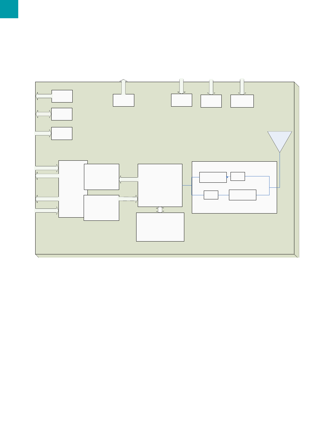
BLOCK DIAGRAM
Figure 1 includes a functional Block Diagram of the transceiver module.
Table 3: Input Characteristics
Signal Name High Min High Max Low Min Low Max Unit
RXD 2.31 3.3 0 .99 V
Test 2.31 3.3 0 .99 V
UP_Reset 0.8 3.3 0 0.6 V
CMD/Data 2.31 3.3 0 .99 V
RTS 2.31 3.3 0 .99 V
AD/_In N/A 3.3 0 N/A V
GI_0 2.31 3.3 0 .99 V
GI_1 2.31 3.3 0 .99 V
Table 4: Output Characteristics
Signal Name High Min Hiigh Max Low Min Low Max Units
GO_0 2.5 3.3 0 0.4 V
GO_1 2.5 3.3 0 0.4 V
PWM_Output N/A 3.3 0 N/A V
TXD 2.5 3.3 0 0.4 V
In_Range 2.5 3.3 0 0.4 V
CTS 2.5 3.3 0 0.4 V
SPECIFICATIONS
6
Serial UART
EEPROM
Input Buffer
768 Bytes
CPU
GPIO
Transmitter
Receiver
Antenna
ADC
Test CMD/
Data
RXD
RTS
TXD
CTS
InRange
PA
UpReset
AC2510
Output Buffer
512 Bytes
LNA
PWM

LAIRD TECHNOLOGIES www.lairdtech.com
H
ARDWARE
I
NTERFACE
3
PIN DESCRIPTIONS
RXD and TXD
The LT2510 accepts 3.3 VDC TTL level asynchronous serial data from the OEM Host via the RXD pin. Data is sent from the
transceiver, at 3.3V levels, to the OEM Host via the TXD pin.
Test
Test Mode - When pulled logic Low before applying power or resetting, the transceiver's serial interface is forced to 9600, 8-N-1
(8 data bits, No parity, 1 stop bit): regardless of actual EEPROM setting. The interface timeout is also set to 3 ms and the RF
packet size is set to the default size for the selected RF Data Rate. To exit, the transceiver must be reset or power-cycled with Test
pin logic High or disconnected.
Note: Because this pin disables some modes of operation, it should not be permanently pulled Low during normal operation.
UP_Reset
UP_Reset provides a direct connection to the reset pin on the LT2510 microprocessor and is used to force a hard reset. For a valid
reset, reset must be asserted Low for an absolute minimum of 250 ns.
Command/Data
When logic High, the transceiver interprets incoming serial data as transmit data to be sent to other transceivers. When logic Low,
the transceiver interprets incoming serial data as command data. When logic Low, data packets from the radio will not be
transmitted over the RF interface however incoming packets from other radios will still be received. RX Data Received can be
disabled by enabling CMD/Data RX Disable in the EEPROM.
In Range
The In Range pin will be driven low when a client radio is synchronized with a server. In Range will always be driven low on a
server.
RTS Handshaking
With RTS mode disabled, the transceiver will send any received data to the OEM Host as soon as it is received. However, some
OEM Hosts are not able to accept data from the transceiver all of the time. With RTS enabled, the OEM Host can prevent the
transceiver from sending it data by de-asserting RTS (High). Once RTS is re-asserted (Low), the transceiver will send packets to
the OEM Host as they are received.
Note: Leaving RTS de-asserted for too long can cause data loss once the transceiver's receive buffer reaches capacity.
CTS Handshaking
If the transceiver buffer fills up and more bytes are sent to it before the buffer can be emptied, data loss will occur. The transceiver
prevents this loss by deasserting CTS High as the buffer fills up and asserting CTS Low as the buffer is emptied. CTS should be
monitored by the Host device and data flow to the radio should be stopped when CTS is High.

THEORY OF OPERATION
8
T
HEORY
OF
O
PERATION
4
SERVER/CLIENT ARCHITECTURE
The LT2510 utilizes a server-client network architecture to synchronize the frequency hopping. Each network must have one radio
configured as a Server and all other radios configured as Clients. When a radio is configured as a Server, it will transmit a beacon
at the beginning of each hop. Radios configured as Clients will default to a receive mode where they are scanning the available
frequencies listening for a beacon from a Server in their network. When a Client detects the Server’s beacon, the client will
synchronize to it and transition the InRange pin low. When the Server and the Client are synchronized they can begin transferring
data.
Each network consists of one, and only one, Server. Multiple networks can exist in the same area, provided the networks are
configured on different Channels. The LT2510 utilizes an intelligent Frequency Hopping algorithm which ensures minimal
interference between two networks. There is no need to synchronize the communications between the networks. The possible
interference between two networks is given by the equation.
Maximum number of interfering bins = #of collocated Servers -1
The LT2510 radio can be configured to hop over 43 or 79 bins, so with two Servers present they will interfere with each other once
every 43 or 79 hops. With 10 collocated Servers, they will interfere a maximum of 9 out of 43 or 79 hops (presuming they are
also transmitting data during each hop).
ADJUSTABLE RF DATA RATE
The LT2510’s RF data rate can be adjusted to provide a trade-off between throughput and range.
Deciding which RF Data Rate to choose depends on the individual application. The fast RF Data Rate will deliver much faster
throughput, but will have much less range. In addition, because the lower data rate solution uses more hops, it is better situated for
collocated networks.
Table 5: RF Data Rate
Product Model RF Data Rate Number of hops Receiver Sensitivity Throughput1
1. Throughput is ideal, one direction, with no retransmissions. All practical RF applications should include the need to retransmit data due to
interference or less than ideal RF conditions
100mW, 200mW, 1W 280kbps 79 -99dB 120kbps
100mW, 200mW 500kbps 43 -94dB 250kbps

LAIRD TECHNOLOGIES www.lairdtech.com
A rule of thumb for RF systems is every 6dB of gain doubles the effective distance. The 5dB gain on the Receive Sensitivity for
the lower data rate solution means it will be able to transmit almost twice as far as the higher data rate solution.
MODES OF OPERATION
The LT2510 has three different types of interface modes:
• Transparent Mode
• API Mode
• Command Mode
The first two modes are used to transmit data across the RF, the third mode is used to configure the radio.
Transparent Mode
When operating in Transparent Mode, the LT2510 can act as a direct serial cable replacement in which received RF data is
forwarded over the serial interface and vice versa. In transparent mode, the radio needs to be programmed with the MAC Address
of the desired recipient. The destination address can be programmed permanently or on-the-fly.
When Transparent Mode is used, data is stored in the TX buffer until one of the following occurs:
• The RF packet size is reached (EEPROM address 0x5A)
• An Interface Timeout occurs (EEPROM address 0x58)
Any parameters can be configured by entering Command Mode using either AT commands or by toggling the Command/Data pin
on the transceiver.
API Mode
API Mode is an alternative to the default Transparent operation of the LT2510 and provides dynamic packet routing and packet
accounting abilities to the OEM Host without requiring extensive programming by the OEM Host. API Mode utilizes specific
frame-based packet formats; specifying various vital parameters used to control radio settings and packet routing on a packet-by-
packet basis. The API features can be used in any combination that suits the OEM’s application specific needs.
API Mode provides an alternative method of configuring modules and message routing at the OEM Host level; without requiring
the use of Command Mode. The LT2510 has three API functions:
• Transmit API
• Receive API
• API Send Data Complete
For additional details and examples, please refer to the API section on page 22.
Command Mode
Command Mode is used to configure and poll for status of the transceiver. Command mode can be entered by issuing the Enter
AT Command string or by setting the CMD/Data pin low. Details of using Command Mode to configure the LT2510 are detailed
in Section 5.
ENGINEERS TIP
A 1000mW version of the LT2510 is planned for North American markets. It will only support a
280kbps, 79 hop RF Data Rate due to agency restrictions. The 500kbps RF Data Rate will be limited to
lower power modules. A current LT2510 on the 280kbps will be able to communicate with the future
LT2510-1000.

THEORY OF OPERATION
10
SERIAL INTERFACE BAUD RATE
In order for the OEM Host and a transceiver to communicate over the serial interface they need to have the same serial data rate.
This value determines the baud rate used for communicating over the serial interface to a transceiver. For a baud rate to be valid,
the calculated baud rate must be within ±3% of the OEM Host baud rate
For baud rates other than those shown in Table 6 the following equations can be used:
Where:
FREQUENCY = 26 MHz
BAUD_M = EEPROM Address 0x43
BAUD_E = EEPROM Address 0x44
Table 6: Baud Rate / Interface Timeout
Desired Baud Rate Baud (0x42) Minimum Interface Timeout1 (0x58)
1. Interface timeout = 200us per increment, this is set automatically with the Auto Config option
230,400 0x0A 0x02
115,2002
2. Default baud rate
0x09 0x02
57,600 0x08 0x02
38,4003
3.
0x07 0x02
28800 0x06 0x03
19,200 0x05 0x05
14400 0x04 0x07
9,600 0x03 0x10
4,800 0x02 0x15
2,400 0x01 0x2A
1,200 0x00 0x53
Non-standard 0xE3 Use equations below
MinimumInterfaceTimeout 100000
Baud Rate
-------------------------=

11
LT2510 User’s Manual THEORY OF OPERATION
LAIRD TECHNOLOGIES www.lairdtech.com
INTERFACE TIMEOUT / RF PACKET SIZE
Interface Timeout – Interface Timeout specifies a maximum byte gap between consecutive bytes. When that byte gap is
exceeded, the bytes in the transmit buffer are processed as a complete packet. Interface Timeout (EEPROM address 0x58), in
conjunction with the RF Packet Size, determines when a buffer of data will be sent out over the RF as a complete RF packet, based
on whichever condition occurs first. Interface Timeout is adjustable in 200us increments and should be equal to or greater than two
full bytes times. The minimum Interface Timeout is 0x02.
RF Packet Size - RF Packet Size is used in conjunction with Interface Timeout to determine when to delineate incoming data as
an entire packet based on whichever condition is met first. When the transceiver receives the number of bytes specified by RF
Packet Size (EEPROM address 0x5A) without experiencing a byte gap equal to Interface Timeout, that block of data is processed
as a complete packet. Every packet the transceiver sends over the RF contains extra header bytes not counted in the RF Packet
Size. Therefore, it is much more efficient to send a few large packets than to send many short packets. The maximum RF Packet
Size is 239 bytes, or 0xEF, at 500kkbps RF Data Rate and 96 bytes, or 0x60, at 280kbps RF Data Rate.
FLOW CONTROL
Although flow control is not required for transceiver operation, it is recommended to achieve optimum system performance and to
avoid overrunning the LT2510’s serial buffers. The LT2510 uses separate buffers for incoming and outgoing data.
RXD Data Buffer and CTS
As data is sent from the OEM Host to the radio over the serial interface, it is stored in the LT2510’s buffer until the radio is ready
to transmit the data packet. The radio waits to transmit the data until one of the following conditions occur (whichever occurs
first):
• The RF packet size is reached (EEPROM address 0x5A)
• An Interface Timeout occurs (EEPROM address 0x58)
The data continues to be stored in the buffer until the radio receives an RF Acknowledgement (ACK) from the receiving radio
(addressed mode), or all transmit retries/broadcast attempts have been utilized. Once an ACK has been received or all
retries/attempts have been exhausted, the current data packet is removed from the buffer and the radio will begin processing the
next data packet in the buffer.
To prevent the radio’s RXD buffer from being overrun, it is strongly recommended that the OEM Host monitor the radio’s CTS
output. When the number of bytes in the RXD buffer reaches the value specified by CTS_ON (EEPROM address 0x5C - 0x5D),
the radio de-asserts (High) CTS to signal to the OEM Host to stop sending data over the serial interface. CTS is re-asserted after
ENGINEER’S TIP
•The LT2510 supports a majority of standard as well as non-standard baud rates. To select a standard baud rate,
use the value shown for EEPROM address 0x42 in Table 6 above. To enable a non-standard baud rate, program
EEPROM address 0x42 (Custom Baud Enable) to 0xE3 and then use the equation above to solve for BAUD_M
and BAUD_E.
•Adjusting the Serial Interface Baud Rate does not affect the RF data rate.
•The Interface Timeout and RF Packet Size will be set automatically based on the Interface Baud Rate if the
Auto Config option is enabled.

THEORY OF OPERATION
12
the number of bytes in the RXD buffer is reduced to the value specified by CTS_OFF (EEPROM addresses 0x5E- 0x5F);
signalling to the OEM Host that it may resume sending data to the transceiver.
Note: It is recommended that the OEM Host cease all data transmission to the radio while CTS is de-asserted (High); otherwise
potential data loss may occur.
TXD Data Buffer and RTS
As data to be forwarded to the OEM Host accumulates, it is stored in the LT2510’s outgoing buffer until the radio is ready to begin
sending the data to the OEM Host. Once the data packet has been sent to the Host over the serial interface, it will be removed from
the buffer and the radio will begin processing the next data packet in the buffer.
With RTS Mode disabled, the transceiver will send any data to the OEM Host as soon as it has data to send. However, some OEM
Hosts are not able to accept data from the transceiver all of the time. With RTS Mode Enabled, the OEM Host can prevent the
transceiver from sending it data by de-asserting RTS (High), causing the transceiver to store the data in its buffer. Upon asserting
RTS up to two additional bytes can be received over the serial interface before the flow is stopped. Once RTS is re-asserted (Low),
the transceiver will continue sending data to the OEM Host, beginning with any data stored in its buffer.
Note: Leaving RTS de-asserted for too long can cause data loss once the radio’s TXD buffer reaches capacity.
ENGINEER’S TIP
Can I implement a design using just TXD, RXD and Gnd (Three-wire Interface)?
Yes. However, it is strongly recommended that your hardware monitor the CTS pin of the radio. CTS is
taken High by the radio when its interface buffer is getting full. Your hardware should stop sending at this
point to avoid a buffer overrun (and subsequent loss of data).
You can perform a successful design without monitoring CTS. However, you need to take into account
the amount of latency the radio adds to the system, any additional latency caused by Transmit Retries,
how often you send data, non-delivery network timeouts and interface data rate.
Larid Technologies can assist in determining whether CTS is required for your application.

13
LT2510 User’s Manual CONFIGURING THE LT2510
LAIRD TECHNOLOGIES www.lairdtech.com
C
ONFIGURING
THE
LT2510
5
The LT2510 can be configured using AT Configuration Commands. These commands can be issued only in Command Mode.
Command Mode can be entered by setting pin 15 of a transceiver asserted low or by entering AT Command Mode before issuing
the Enter AT Command.
AT COMMANDS
The AT Command mode implemented in the LT2510 creates a virtual version of the Command/Data pin. The “Enter AT Command
Mode” Command asserts this virtual pin Low (to signify Command Mode) and the “Exit AT Command Mode” Command asserts
this virtual pin High (to signify Data). Once this pin has been asserted Low, all AT Commands documented in the manual are
supported.
There are four types of AT Commands supported by the LT2510. On-the-Fly commands for dynamic reprogramming of running
memory, EEPROM commands for configuring the EEPROM, Utility commands for dealing with Command Mode and Status
Commands for polling the radio for information.
While in Command mode, the incoming RF interface of the transceiver is active and packets sent from other transceivers will still
be received; however no outgoing RF packets will be sent. The transceiver uses Interface Timeout/RF Packet Size to determine
when an AT Command is complete. Therefore, there should be no delay between each character as it is sent from the OEM Host to
the transceiver or the transceiver will not recognize the command.
When an invalid command is sent, the radio discards the data and no response is sent to the OEM Host. Table 7 below shows a
quick summary of the basic configuration & diagnostic commands available on the LT2510. For detailed command information,
please refer to the command descriptions immediately following the Quick Reference Table
Utility Commands
Utility Commands are used to enter and exit AT Command Mode and to reset the radio.
On-the-Fly Control Commands
The LT2510 transceiver contains memory that holds many of the parameters that control the transceiver operation. Using the On-
the-Fly command set allows many of these parameters to be viewed and changed during system operation. Because the memory
these commands affect is dynamic, when the transceiver is reset, these parameters will revert back to the settings stored in the
EEPROM.
Status Commands
Status Commands are used to poll the radio for information. Status commands can be used to poll GPIOs, ADCs or to retrieve
information about the state of the network. Status commands do not affect the operation of the transceiver aside from being in
Command Mode.

LAIRD TECHNOLOGIES www.lairdtech.com
EEPROM Configuration Commands
Two Commands are available to read and write the EEPROM of the radio. These commands are very powerful as they can control
the entire configuration of the radio. They should be used with caution as overwriting reserved areas of memory can adversely
affect the operation of the radio. The radio must be reset for any changes to the EEPROM to take affect.
COMMAND QUICK REFERENCE
Table 4 provides an at-a-glance view of all available AT commands.
.
Table 7: Command Quick Reference
Command Name Command (All bytes in Hex) Return (All bytes in Hex)
Utility Commands
Enter AT Command Mode <0x41> <0x54> <0x2B> <0x2B> <0x2B> <0x0D> <0xCC> <0x43> <0x4F> <0x4D>
Exit AT Command Mode <0xCC> <0x41> <0x54> <0x4F> <0x0D> <0xCC> <0x44> <0x41> <0x54>
Enter Deep Sleep <0xCC> <0x86> <0x03> None
Soft Reset <0xCC> <0xFF> None
Status Commands
Status Request <0xCC> <0x00> <0x00> <0xCC> <Firmware Version> <Status>
Read Temperature <0xCC> <0xA4> <0xCC> <Temperature>
On-the-Fly Commands
Change Channel <0xCC> <0x02> <Channel> <0xCC> <Channel>
Change Server/Client Mode <0xCC> <0x03> <Data> <0xCC> <Firmware Version> <Status>
Set Broadcast Mode <0xCC> <0x08> <Data> <0xCC> <Data>
Write Destination Address <0xCC> <0x10> <Dest Address last thee bytes> <0xCC> <Dest Addr>
Read Destination Address <0xCC> <0x11> <0xCC> <Dest Addr>
Auto Destination/Channel <0xCC> <0x15> <Data> <0xCC> <Data>
Read API Control <0xCC> <0x16> <0xCC> <API Control>
Write API Control <0xCC> <0x17> <API Control> <0xCC> <API Control>
Read Digital Input <0xCC> <0x20> <0xCC> <Data>
Read ADC <0xCC> <0x21> <Data> <0xCC> <ADC Hi> <ADC Lo>
Write PWM Output <0xCC> <0x24> <Data> <0xCC> <0x24>
Write Digital Outputs <0xCC> <0x23> <Data> <0xCC> <0x23>
Set Power Control <0xCC> <0x25> <Power> <0xCC> <Power>
EEPROM Commands
EEPROM Byte Read <0xCC> <0xC0> <Start> <Length> <0xCC> <Start> <Length> <Data [n-0]>
EEPROM Byte Write <0xCC> <0xC1> <Start> <Length> <Data> <Start> <Length> <Last byte written>

15
LT2510 User’s Manual CONFIGURING THE LT2510
LAIRD TECHNOLOGIES www.lairdtech.com
COMMAND DESCRIPTIONS
Advanced Networking Commands
Bin Analyzer <0xCC> <0x8F> <Data> <0xCC> <0x8F>
Enter AT Command Mode
Prior to sending this command, the OEM Host must ensure that the
transceiver’s RF transmit buffer is empty. This can be accomplished by
waiting up to one second between the last packet and the AT command. If
the buffer is not empty, the radio will interpret the command as data and it
will be sent over the RF.
Command: <0x41> <0x54> <0x2B> <0x2B> <0x2B> <0x0D>
Number of Bytes Returned: 4
Response: <0xCC> <0x43> <0x4F> <0x4D>
Exit AT Command Mode
The OEM Host should send this command to exit AT Command mode and
resume normal operation.
Command: <0xCC> <0x41> <0x54> <0x4F> <0x0D>
Number of Bytes Returned: 4
Response: <0xCC> <0x44> <0x41> <0x54>
Enter Deep Sleep
The OEM Host issues this command to put the module into a Deep Sleep
state to minimize current draw. In this state a Server will not send out a
beacon, a Client will not remain In Range and no commands sent over the
Serial UART will be processed. To awake from Deep Sleep the OEM must
toggle the Up_Reset pin.
Command: <0xCC> <0x86> <0x03>
Number of Bytes Returned: None
Response: None
Reset
The OEM Host issues this command to perform a soft reset of the
transceiver. Any transceiver settings modified by CC commands will revert
to the values stored in the EEPROM.
Command: <0xCC> <0xFF>
Number of Bytes Returned: None
Response: None
Status Version Request
The OEM Host issues this command to request the firmware and link status
of the transceiver.
Command: <0xCC> <0x00> <0x00>
Number of bytes returned: 3
Response: <0xCC> <Firmware Version> <Status>
Parameter Range:
<Firmware> = Radio Firmware version
<Status> = 0x02: Server
0x03: Clients In Range
0x01: Client not In Range
Read Temperature
Table 7: Command Quick Reference
Command Name Command (All bytes in Hex) Return (All bytes in Hex)

CONFIGURING THE LT2510
16
The OEM Host issues this command to read the onboard temperature sensor.
Note: The temperature sensor is uncalibrated and has a tolerance of +/- 3C.
For calibration instructions, contact Laird Technology’s technical support.
Command: <0xCC> <0xA4>
Number of bytes returned: 2
Response: 0xCC <Temp.>
Parameter Range:
<Temp.> = Temperature (Celsius) in Two’s compliment format
Change Channel
The OEM Host issues this command to change the channel of the
transceiver.
Command: <0xCC> <0x02> <Channel>
Number of Bytes Returned: 2
Response: <0xCC> <Channel> <ChMask>
Parameter Range:
<Channel> = 0x00 - 0x4E RF Channel to use
Change Server/Client Mode
The OEM Host issues this command to change the transievers mode from
Server to Client or vice-versa.
The OEM can use Bit 1 to force the status of the transiever.
Command: <0xCC> <0x03> <Data>
Number of Bytes Returned: 3
Response: <0xCC> <Firmware Version> <Status>
Parameter Range:
<Data> = Bit0::
0= Server
1= Client
Bit1::
0= Force InRange
1= Force Out of Range
<Firmware> = Radio Firmware version
<Status> = 0x02: Server
0x03: Clients In Range
0x01: Client not In Range
Set Broadcast Mode
The Host issues this command to set the addressing mode in the radio. Command: <0xCC> <0x08> <Data>
Number of Bytes Returned: 2
Response: <0xCC> <Data>
Parameter Range:
<Data> = 0x00 Disable Broadcast Mode
0x01 Enable Broadcast Mode
Write Destination Address
The OEM Host issues this command to the transceiver to change the
Destination Address.
Command: <0xCC> <0x10> <MAC1> <MAC2> <MAC3>
Number of bytes returned: 4
Response: <0xCC> <MAC1> <MAC2i> <MAC3>
Parameter Range:
0x00 - 0xFF corresponding to the 3 LSBs of the destination MAC Address
Read Destination Address

17
LT2510 User’s Manual CONFIGURING THE LT2510
LAIRD TECHNOLOGIES www.lairdtech.com
The OEM Host issues this command to the transceiver to read the
Destination Address.
Command: <0xCC> <0x11>
Number of bytes returned: 4
Response: <0xCC> <MAC1> <MAC2> <MAC3>
Parameter Range:
0x00 - 0xFF corresponding to the 3 LSBs of the destination MAC Address
Auto Destination/Channel
The Host issues this command to change the Auto Destination setting. When
issuing this command, the Auto Destination setting will only be changed if
the corresponding enable bit is set. Otherwise, the command performs a read
of Auto Destination.
Command: <0xCC> <0x15> <Data>
Number of Bytes Returned: 2
Response: <0xCC> <Auto Dest>
Parameter Range:
<Auto Dest> = bit 7: Ignored
bit 6: Ignored
bit 5: Enable Modification of Auto Channel
bit 4: Enable Modification of Auto Destination
bit 3: Ignored
bit 2: Ignored
bit 1: Auto Channel
bit 0: Auto Destination
Read API Control
The OEM Host issues this command to read the API Control byte. Command: <0xCC> <0x16>
Number of Bytes Returned: 2
Response: <0xCC> <API Control>
Parameter Range:
<API Control>= bits 7-3: 0
bit-2: Send Data Complete
bit-1: Transmit API
bit-0: Receive API
Write API Control
The OEM Host issues this command to write the API Control byte to enable
or disable the API features.
Command: <0xCC> <0x17> <API Control>
Number of Bytes Returned: 2
Response: <0xCC> <API Control>
Parameter Range:
<API Control>= bits 7-3: Ignored
bit-2: Send Data Complete
bit-1: Transmit API
bit-0: Receive API
Read Digital Outputs

CONFIGURING THE LT2510
18
The OEM Host issues this command to read the state of both digital output
lines.
Command: <0xCC> <0x20>
Number of Bytes Returned: 2
Response: 0xCC <Digital Out>
Parameter Range:
<Digital Out> = bit-1: GO1
bit-0: GO0
Read ADC
The OEM host issues this command to read the analog to digital converters
at up to 12-bit resolution. Higher resolutions can cause slower responses
from the command. The time required for a conversion is
Tconv = (decimation rate + 16) * .23uS.
In the most common forms this will be used to measure theinput voltage (to
detect reduced battery power) with Vdd/3, the temperature sensor or the
Analog input on Pin 22. For the most accurate results the 1.25V internal
reference should be chosen, though this would limit the OEM to a maximum
AD/In of 1.25 v [Vdd/3 and Temperature Sensor should always be below
1.25v]
The ADC result is represented in a two’s complement form. The result is
the difference between ground and the selected channel and will be a value
between -2048 and 2047 with 2047 representing the maximum value where
the ADC result equals the reference voltage and -2048 equals the negative of
the reference voltage. The ADC cannot measure a voltage higher than the
reference voltage.
Command: <0xCC> <0x21> <Data>
Number of Bytes Returned: 3
Response: 0xCC <Hi ADC> <Lo ADC>
Parameter Range:
<Data bits 6-7>= <Reference Voltage>
00: Internal 1.25V reference
10: Vdd on AVdd pin
<Data bits 4-5>= <Resolution>
00: 64 decimation rate (7 bits resolution)
01: 128 decimation rate (9 bits resolution)
10: 256 decimation rate (10 bits resolution)
11: 512 decimation rate (12 bits resolution)
<Data bits 0-3>= <Channel>
0000: AD/In PIn 22
1100: GND
1101: Positive Voltage Reference
1110: Temperature Sensor
1111: Vdd/3
<Hi ADC> = MSB or requested 12-bit ADC value
<Lo ADC> = LSB of reequested 12-bit ADC value
Write PWM Outputs
The OEM Host issues this command to set the PWM_Output. The PWM
output is a repeating 630.1uS period. The PWM ratio is the ratio of the high
pulse time to the low pulse time. A value of 0x00 will output a continuous
low signal. A ratio of 0xFF will output a continuous high signal. A ratio of
0x80 will put out a repeating pulse of 315.05uS high and 315.05uS low.
Command: <0xCC> <0x24> <PWM Ratio>
Number of Bytes Returned: 2
Response: 0xCC <0x24>
Parameter Range:
<PWM Ratio> = 0x00 -0xFF, the ratio of the high pulse versus the low
pulse for a single period.
Write Digital Outputs
The OEM Host issues this command to write both digital output lines to
particular states.
Command: <0xCC> <0x23> <Digital Out>
Number of Bytes Returned: 2
Response: 0xCC <0x23>
Parameter Range:
<Digital Out> = bit-1: GO1
bit-0: GO0
Set Max Power

19
LT2510 User’s Manual CONFIGURING THE LT2510
LAIRD TECHNOLOGIES www.lairdtech.com
The OEM Host issues this command to adjust the maximum output power. Command: <0xCC> <0x25> <Max Pwr>
Number of Bytes Returned: 2
Response: 0xCC <Max Pwr>
Parameter Range:
<Max Pwr> = Power
0x00: 21 dBm
0x01: 15 dBm
0x02: 9 dBm
0x03: 3 dBm
EEPROM Byte Read
Upon receiving this command, a transceiver will respond with the desired
data from the addresses requested by the OEM Host.
Command: <0xCC> <0xC0> <Start> <Length>
Number of Bytes Returned: 4+
Response: <0xCC> <Start> <Length> <Data>
Parameter Range:
<Start> = EEPROM address to begin reading at
<Length> = Length of data to be read
<Data> = Requested data
EEPROM Byte Write
Upon receiving this command, a transceiver will write the data byte to the
specified address but will not echo it back to the OEM Host until the
EEPROM write cycle is complete.
Note: The maximum length of data that can be written in a single write
process is 0x50. If writing the entire 256-byte EEPROM, it is convenient to
perform 64 byte (0x40) writes.
Command: <0xCC> <0xC1> <Start> <Length> <Data>
Number of Bytes Returned: 3
Response: <Start> <Length> <Last byte>
Parameter Range:
<Start> = EEPROM address to begin writing at
<Length> = Length of data to be written (Max = 0x50)
<Data> = Data to be written
<Last byte> = Value of last byte written
Bin Analyzer
The Bin Analyzer is a powerful command for understanding the link
conditions between two radios over the entire frequency hopping spectrum.
The Bin Analyzer will cause the local radio to send a special Bin Analyzer
packet to the radio in the Desitnation field. The remote radio will respond
with RSSI information and this is then streamed to the OEM through the
Serial UART.
Due to the random frequency hopping sequence of the radios, it is not
possible to associate a specific bin # with a specific frequency, though the
OEM can use the Bin Analyzer response to identify any possible interferers
and to provide a quantitative analysis of the total number of good versus
bad bins.
The Bin Analyzer command will stream data results back for each hop until
the command is turned off or the number of runs is met.
The Bin Analyzer command must be issued from Command Mode, but it
will continue to stream results back even after the OEM has exited
Command Mode. The Bin Analyzer packet is sent as part of the RF Packet
Header and does not affect the throughput of data between two radios.
Command: <0xCC> <0x8F> <Control> <NumRuns>
Number of Bytes Returned: 2
Response: <0xCC> <0x8F>
Bin Response Stream: <0xCC> <Bin#> <RSSI_1> <RSSI_2>
Parameter Range:
<Control> = 0x00= Turn Bin Analyzer Off
0x01= Turn Bin Analyzer On
<NumRuns> = 0x00= Continous
0x01- 0xFF= Number of runs [bins]
<Bin#> = Bin# from 0-79 or 0-53 depending on the RF Data
Rate
<RSSI_1> = RSSI the remote radio heard the local radio’s bin
request
<RSSI_2> = RSSI the local radio heard the remote radio’s response

LAIRD TECHNOLOGIES www.lairdtech.com
EEPROM P
ARAMETERS
6
The OEM Host can program various parameters that are stored in EEPROM and become active after a power-on reset. The table
below gives the locations and descriptions of the parameters that can be read/written by the OEM Host. Factory default values are
also shown. Do not write to any EEPROM addresses other than those listed below. Do not copy one transceiver’s EEPROM to
another transceiver as doing so may cause the transceiver to malfunction.
Table 8: EEPROM Parameters
Parameter EEPROM
Address Length
(Bytes) Range Default Description
Product ID 0x00 40 Product identifier string. Includes revision
information for software and hardware.
Range Refresh 0x3D 1 0x01-
0xFF 0x18 Specifies the maximum amount of time a transceiver
will report In Range without having heard a Server’s
beacon. Equal to hop period * value, do not set to
0x00.
Channel Number 0x40 1 0x00 -
0x4F 0x00 RF Channel Number, used to determine the hopping
sequence.
Baud Rate 0x42 1 0x00 -
0x0A 0x09 Baud Rate, see serial interface section for details.
Default represents 115,200kbps.
Transmit Retries 0x4C 1 0x01 -
0xFF 0x03 Maximum number of times a packet is transmitted
when Addressed packets are selected.
Note: Do not set to 0.
Broadcast Attempts 0x4D 1 0x01 -
0xFF 0x03 Number of times each packet is transmitted when
Broadcast packets are selected.
Note: Do not set to 0.
Control 1 0x56 1 0x00 -
0xFF 0x40 Settings are:
bit-7: Reserved
bit-6: Reserved
bit-5: Reserved
bit-4: Auto Destination
0 = Use destination address
1 = Use auto destination
bit-3: Client Auto Channel
0 = Disable Auto Channel
1 = Enable Auto Channel
bit-2: Reserved
bit-1: Duplex
0 = Half Duplex
1 = Full Duplex
bit-0: Reserved
Interface Timeout 0x58 1 0x02 -
0xFF 0x02 Specifies a byte gap timeout, used in conjunction
with RF Packet Size to determine when a packet
coming over the interface is complete (200us per
increment).

21
LT2510 User’s Manual EEPROM PARAMETERS
LAIRD TECHNOLOGIES www.lairdtech.com
RF Packet Size 0x5A 1 0x01 -
0xEF 0xEF Used in conjunction with Interface Timeout;
specifies the maximum size of an RF packet.
Note: Must be set to a minimum of 6 in order to send
the Enter AT command.
CTS On 0x5C 2 0x0000 -
0x02C0 0x0280 CTS will be de-asserted (High) when the transmit
buffer contains at least this many characters.
CTS Off 0x5E 2 0x0000 -
0x02C0 0x0200 Once CTS has been de-asserted, CTS will be
reasserted (Low) when the transmit buffer is
contains this many or less characters.
Max Power 0x63 1 0x00 -
0x03 0x00 Used to increase/decrease the output power.
0x00 21dBm
0x001 10dBm
0x02 4dBm
0x03 0dBm
Note: The transceivers are shipped at maximum
allowable power.
Destination MAC Address 0x70 6 0x00 -
0xFF 0xFF Specifies destination for RF packets
System ID 0x76 1 0x00 -
0xFF 0x01 Similar to network password. Radios must have the
same system ID to communicate with each other.
Control 2 0xC1 1 0x01 -
0xFF 0x00 Settings are:
bit-7: Broadcast Mode
0 = Disable
1 = Enable
bit-6: Reserved
bit-5: Reserved
bit-4: Reserved
bit-3: Unicast Only
0 = Disable
1 = Enable
bit-2: Send Data Complete API
0 = Disable
1 = Enable
bit-1: Transmit API
0 = Disable
1 = Enable
bit-0: Receive API
0 = Disable
1 = Enable
D.O.B. 0xE0 4Provides factory calibration and test date.
Table 8: EEPROM Parameters
Parameter EEPROM
Address Length
(Bytes) Range Default Description

LAIRD TECHNOLOGIES www.lairdtech.com
API O
PERATION
7
API Operation is a powerful alternative to the default Transparent operation of the LT2510 and provides dynamic packet
accounting abilities to the OEM Host without requiring extensive programming by the OEM Host. API operation utilizes specific
packet formats. The API features can be used in any combination that suits the OEM’s specific needs and can be different between
radios operating on the same network.
API SEND DATA COMPLETE
API Send Data complete can be used as a software acknowledgement indicator. When a radio sends an addressed packet, it will
look for a received acknowledgement (transparent to the OEM Host). If an acknowledgement is not received, the packet will be
retransmitted until one is received or all retries have been exhausted.
For applications where data loss is not an option, the OEM Host may wish to monitor the acknowledgement process using the API
Send Data Complete. If an acknowledgement is not received (Failure), the OEM Host can send the packet to the transceiver once
again.
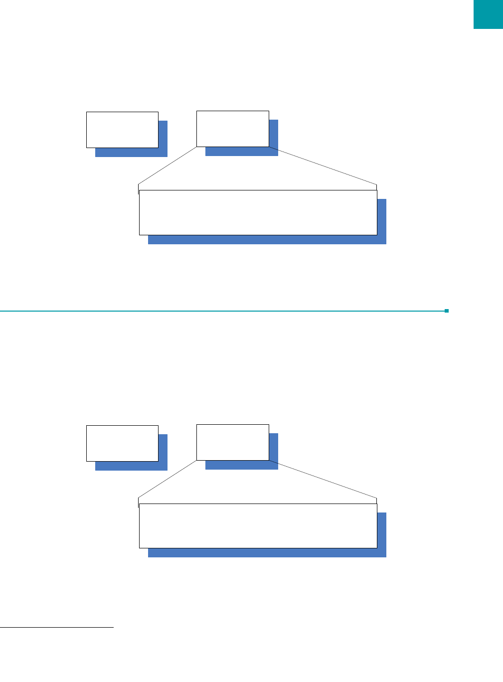
API Send Data Complete is enabled when bit-2 of the Control 2 (Address 0xC1) byte is enabled. The transceiver sends the OEM
Host the data shown in Figure 1 upon receiving an RF acknowledge or exhausting all attempts.
Figure 1: Send Data Complete packet format
API RECEIVE PACKET
By default, the source MAC is not included in the received data string sent to the OEM Host. For applications where multiple
radios are sending data, it may be necessary to determine the origin of a specific data packet. When API Receive Packet is enabled,
all packets received by the transceiver will include the MAC address of the source radio as well as an RSSI indicator which can be
used to determine the link quality between the two.
API Receive Packet is enabled when bit-0 of the Control 2 (Address 0xC1) byte is enabled. Upon receiving a RF packet, the radio
sends its OEM Host the data as shown in Figure 2 below.
Data
Request
0x82
Start Delimiter
Data
Byte 2: Transmit RSSI
Byte 3: Receive RSSI
Byte 4: Success
0x00: Fail
0x01: Success
23
LT2510 User’s Manual API OPERATION
LAIRD TECHNOLOGIES www.lairdtech.com
Figure 2: Receive API packet format
API TRANSMIT PACKET
API Transmit Packet is a powerful API Mode that allows the OEM Host to send data to a single or multiple (via Broadcast)
transceivers on a packet-by-packet basis. This can be useful for many applications; including polling networks and mesh
networks.
API Transmit Packet is enabled when bit-1 of the Control 2 (address 0xC1) byte is enabled. The OEM should pre-pend each
packet of data with the following header information.
Figure 3: Transmit API packet format1
1.Setting the Destination Address to 0xFF 0xFF 0xFF will broadcast the packet to all available transceivers in the network.
Data
Request
0x81
Start Delimiter
Data
Bytes 2: Payload Data Length.
Byte 3: Reserved
Byte 4: Received RSSI
Byte 5-7: 3 LSBs of Sender’s MAC Address
Bytes 8-n: Payload Data
Data
Request
0x81
Start Delimiter
Data
Bytes 2: Payload Data Length. (0x01 – 0x50)
Byte 3: Reserved
Byte 4: Transmit Retries/Broadcast Attempts
Byte 5-7: 3 LSBs of Destination MAC Address
Bytes 8-n: Payload Data
LAIRD TECHNOLOGIES www.lairdtech.com
D
IMENSIONS
8
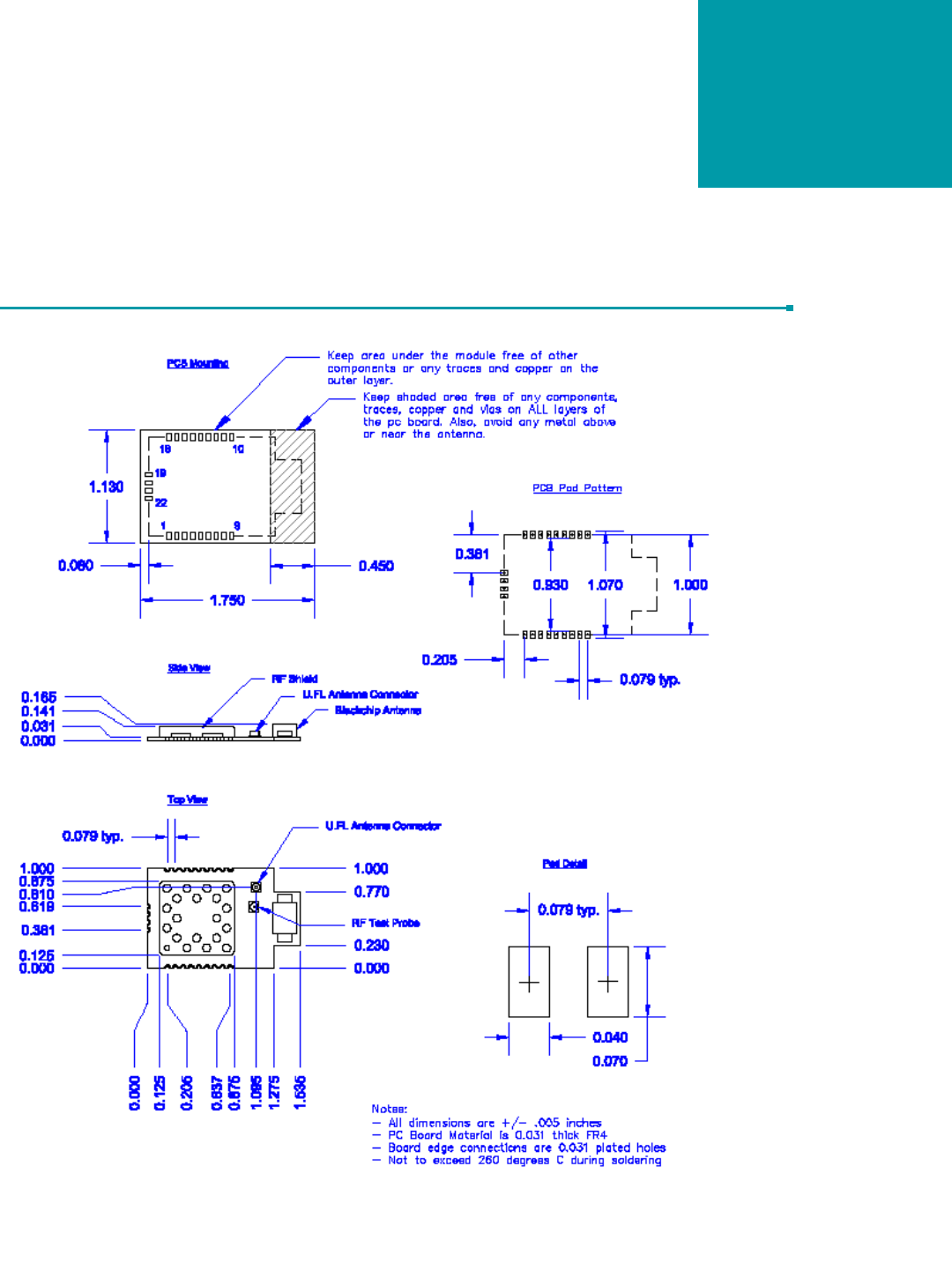
MECHANICAL DRAWING
Figure 4: Mechanical Drawing

LAIRD TECHNOLOGIES www.lairdtech.com
O
RDERING
I
NFORMATION
9
PRODUCT PART NUMBERS
Table 9: LT2510 Part Numbers
Part Number Description
PRM110 100W, Chip Antenna
PRM111 100mW, U.FL
PRM121 100mW with U.FL mounted on AC4424 compatible board
Table 10: LT2510 Development Kit Part Numbers
Part Number Description
DVK-PRM110 Full Development kit with two radios with Chip Antennas
and accessories
EVB-PRM112 One 100mW radio with Chip antenna on USB eval board
EVB-PRM113 One 100mW radio with Chip antenna on RS-232 eval board
DVK-PRM111 Full Development kit with two radios with U.FL connectors
and accessories
EVB-PRM114 One 100mW radio with U.FL connectors on USB eval
board
EVB-PRM115 One 100mW radio with U.FL Connectors on RS-232 eval
board

LAIRD TECHNOLOGIES www.lairdtech.com
C
OMPLIANCY
I
NFORMATION
10
AGENCY IDENTIFICATION NUMBERS
APPROVED ANTENNA LIST
The following antennas are approved for operation with the LT2510 as identified. .
This device has been designed to operate with the antennas listed below, and having a maximum gain of 6dB when hopping over
43 hop bins and 9dB when hopping over 79 hop bins.. Antennas not included in this list or having a gain greater than the maximum
allowed are strictly prohibited for use with this device. The required antenna impedance is 50 Ohms.
FCC / IC REQUIREMENTS FOR MODULAR APPROVAL
In general, there are two agency classifications of wireless applications; portable and mobile.
Portable - Portable is a classification of equipment where the user, in general, will be within 20 cm of the transmitting antenna.
Portable equipment is further broken down into two classes; within 2.5 cm of human contact and beyond 2.5 cm. The LT2510 is
not agency approved for portable applications. The OEM is required to have additional testing performed to receive this
classification. Contact Laird Technology for more details.
Mobile - Mobile defines equipment where the user will be 20 cm or greater from the transmitting equipment. The antenna must be
Table 11: Agency Identification Numbers
Part Number US/FCC CANADA/IC ETSI
LT2510 KQL-2510100 2268C-2510100 Pending
Table 12: LT2510 Approved Antenna List1
1. The OEM is free to choose another vendor’s antenna of like type and equal or lesser gain as an antenna
appearing in the table and still maintain compliance
Laird Technology Part
Number Manufacturer Part
Number Manufacturer Type Gain
(dBi)
WIC2450-A Laird Chip 2
IG2450-RS36 Laird Technologies Omni 6
ID2450-RS362
2. To comply with the power requirements of 15.247(b)(1) and 15.247(b)(4), the module cannot be used with the 9dBi antenna if
using the 43 channel hop sequence and full power. The module must either hop over the full 79 channels or the power setting
must be turned down to 0x01 or lower.
Laird Technologies Panel 9
S151FC-L-(132)PX-2450S Nearson Dipole 5

27
LT2510 User’s Manual COMPLIANCY INFORMATION
LAIRD TECHNOLOGIES www.lairdtech.com
mounted in such a way that it cannot be moved closer to the user with respect to the equipment, although the equipment may be
moved.
This equipment has been approved for mobile applications where the equipment should be used at distances greater than 20cm
from the human body. Operation at distances of less than 20cm would require additional RF exposure evaluation, including SAR
requirement according to FCC RF exporsure guideline.
NOTE: This equipment has been tested and found to comply with the limits for a Class B digital device, pursuant to Part 15 of the
FCC Rules. These limits are designed to provide reasonable protection against harmful interference in a residential installation.
This equipment generates, uses and can radiate radio frequency energy and, if not installed and used in accordance with the
instructions, may cause harmful interference to radio communications. However, there is no guarantee that interference will not
occur in a particular installation. If this equipment does cause harmful interference to radio or television reception, which can be
determined by turning the equipment off and on, the user is encouraged to try to correct the interference by one or more of the
following measures:
• Reorient or relocate the receiving antenna.
• Increase the separation between the equipment and receiver.
• Connect the equipment into an outlet on a circuit different from that to which the receiver is
connected.
• Consult the dealer or an experienced radio/TV technician for help.
OEM EQUIPMENT LABELING REQUIREMENTS
WARNING: The OEM must ensure that FCC labeling requirements are met. This includes a clearly visible label on the outside of
the OEM enclosure specifying the appropriate Laird Technology FCC identifier for this product as well as the FCC notice below.
The FCC identifiers are listed above.
Label and text information should be in a size of type large enough to be readily legible, consistent with the dimensions of the
equipment and the label. However, the type size for the text is not required to be larger than eight point.
ANTENNA REQUIREMENTS
To reduce potential radio interference to other users, the antenna type and gain should be chosen so that the equivalent
isotropically radiated power (e.i.r.p.) is not more than that permitted for successful communication.
WARNING: This device has been tested with a U.FL connector with the above listed antennas. When integrated into the OEM’s
product, these fixed antennas require professional installation preventing end-users from replacing them with non-approved
antennas. Any antenna not listed in the above table must be tested to comply with FCC Section 15.203 for unique antenna
connectors and Section 15.247 for emissions. Contact Laird Technology for assistance.
Caution: Any changes or modifications not expressly approved by Laird Technology could void the user’s authority to operate the
equipment.
Contains FCC ID: KQL-2510100
The enclosed device complies with Part 15 of the FCC Rules. Operation is subject to the following two conditions: (1) This device may not cause
harmful interference, and (2) This device must accept any interference received, including interference that may cause undesired operation.

COMPLIANCY INFORMATION
28
WARNINGS REQUIRED IN OEM MANUALS
WARNING: This equipment has been approved for mobile applications where the equipment should be used at distances greater
than 20cm from the human body. Operation at distances of less than 20cm is strictly prohibited and requires additional SAR
testing.