Laird Connectivity 44249AJ RF Transceiver Module User Manual
AeroComm Corporation RF Transceiver Module Users Manual
UserManual.wiki
>
Laird Connectivity
>
44249AJ User Manual
Users Manual
Navigation menu
Upload a User Manual
Namespaces
Wiki Guide
HTML
PDF
Info
Views
User Manual
Discussion / Help
Navigation
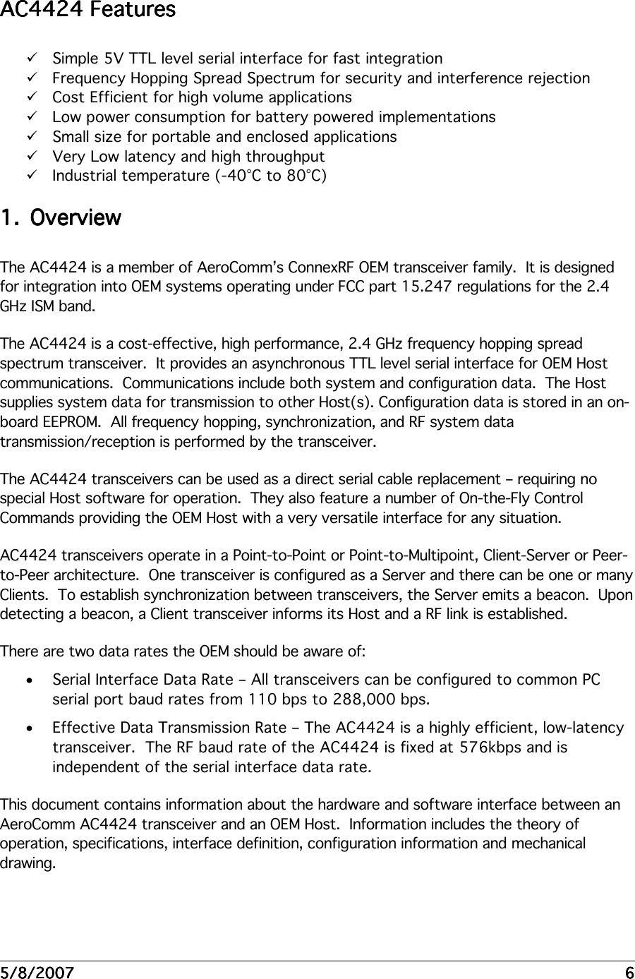


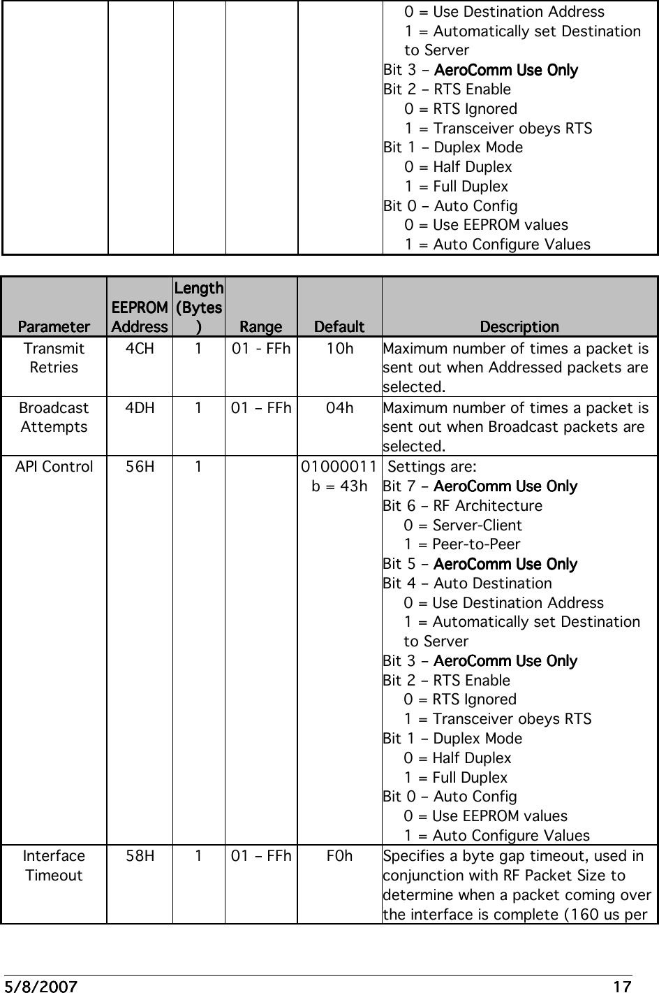
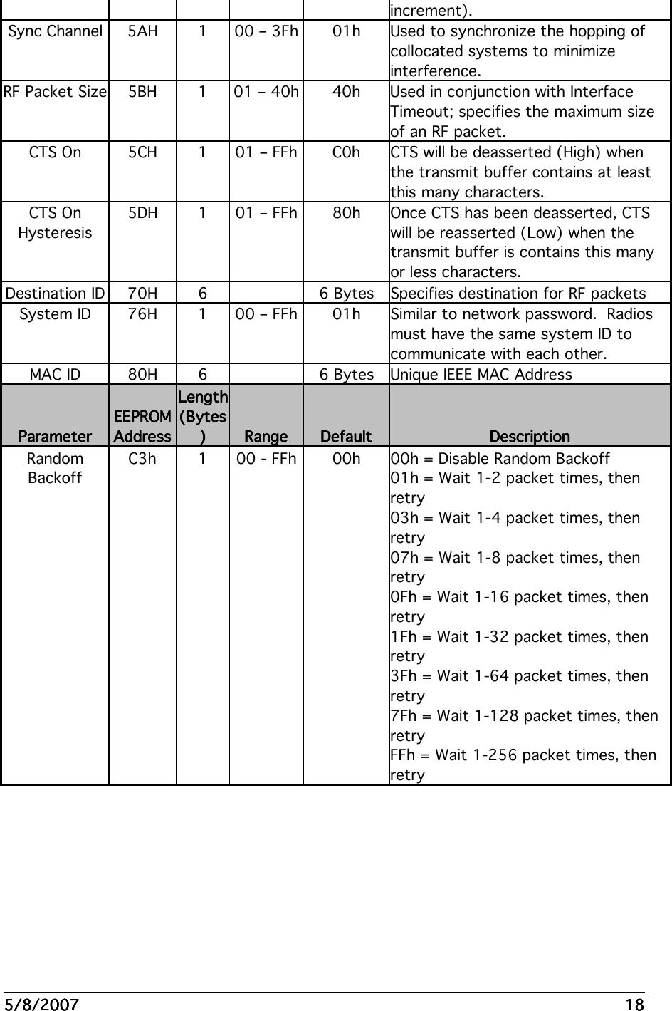
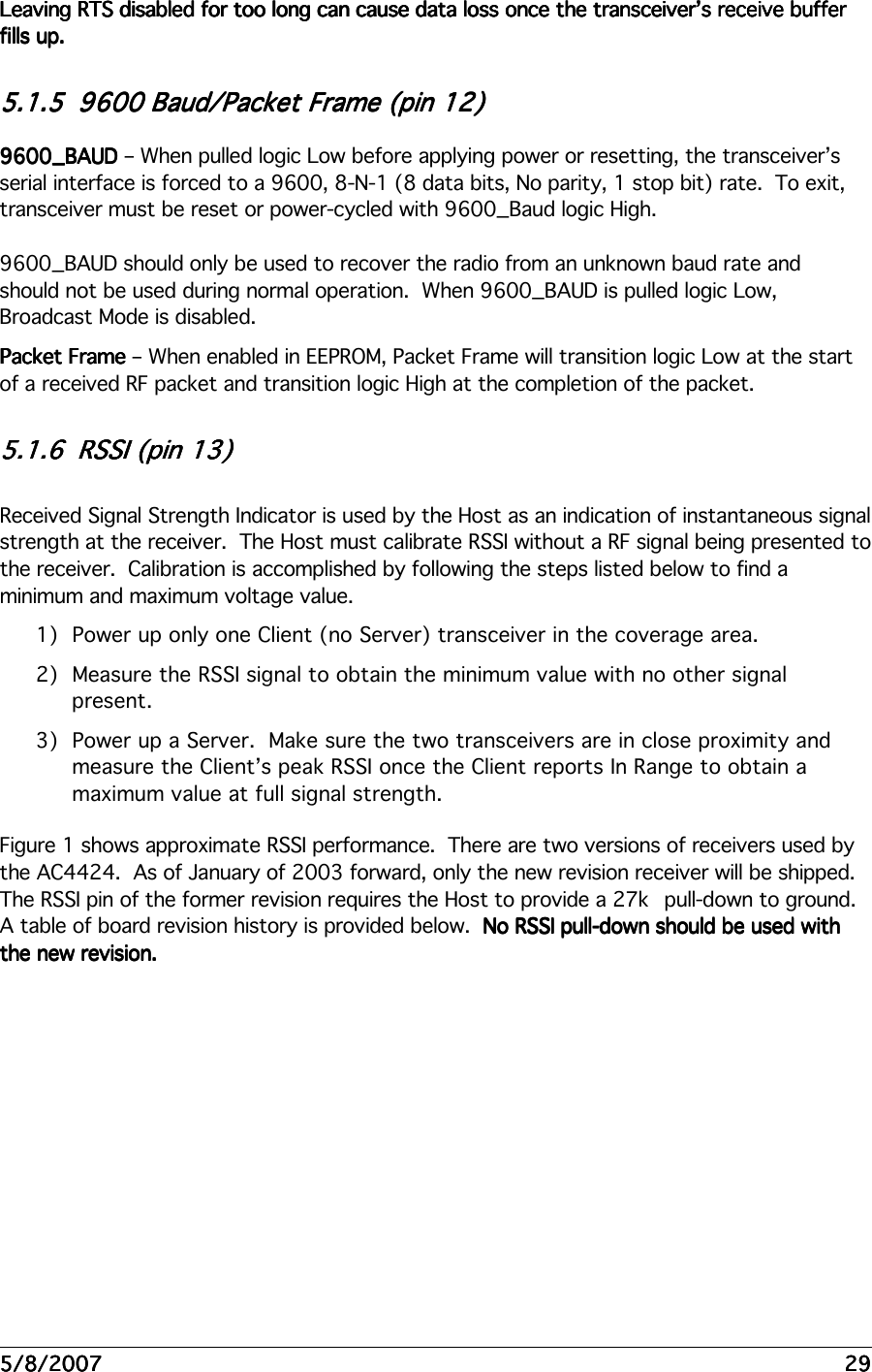
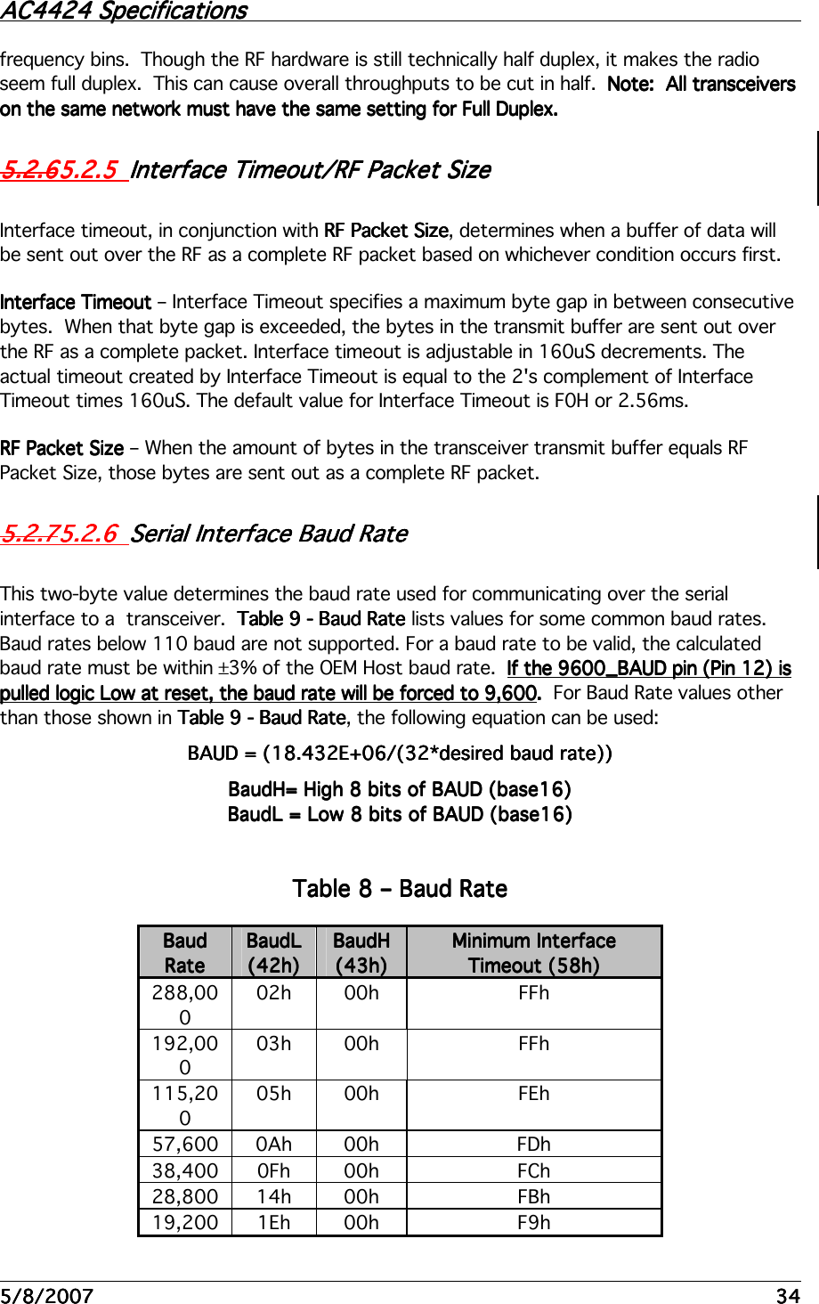
![5555////8/20078/20078/20078/2007 33333333 5.2.35.2.35.2.35.2.3 Random Back OffRandom Back OffRandom Back OffRandom Back Off Random Back Off Random Back Off Random Back Off Random Back Off – If multiple AC4424 transceivers try to send packets out over the RF at the exact same time, the packets will collide and will not be received by the intended receiver. In fact, if after a collision occurs, both transceivers retry at the same time, the retry will also fail. To avoid further collisions, a transceiver can be programmed to wait a random number of packet times (hops) before resending its data. The amount of randomness is controlled by this parameter and this feature is not valid in broadcast mode. Keep in mind that selecting a larger value for Random Back Off will increase the overall latency of the AC4424. The latency calculation becomes: Worst Case Latency = 8ms Hop * # of retries * Maximum Random Value [multiply by 16ms if using Full Duplex mode] Latency is a very important consideration when using a wireless device. The AC4424 has a 256 byte interface buffer. If, due to latency, the radio cannot send the data out over the RF as fast as data is coming into the radio over the serial interface, the buffer will eventually fill up. If data continues coming into the radio once the buffer is full, the buffer will overflow and the new incoming data will be lost. It is strongly recommended that the radio host monitor the CTS pin to avoid this situation. The transceiver asserts this pin high as the buffer is filling to signal the OEM Host to stop sending data. The transceiver will take CTS Low once the buffer becomes less full.Random Backoff Settings: • 00h – Wait 1 packet time, then retry (Random Back Off is disabled) • 01h – Wait 1 – 2 packet times, then retry • 03h – Wait 1 – 4 packet times, then retry • 07h – Wait 1 – 8 packet times, then retry • 0Fh – Wait 1 – 16 packet times, then retry • 1Fh – Wait 1 – 32 packet times, then retry • 3Fh – Wait 1 – 64 packet times, then retry • 7Fh – Wait 1 – 128 packet times, then retry • FFh – Wait 1 – 256 packet times, then retry 5.2.55.2.55.2.55.2.55.2.45.2.45.2.45.2.4 Duplex ModeDuplex ModeDuplex ModeDuplex Mode In Half Duplex mode, the AC4424 will send a packet out over the RF when it can. This can cause packets sent at the same time by a Server and a Client to collide with each other over the RF. To prevent this, Full Duplex Mode can be enabled. This mode restricts Clients to transmitting on odd numbered frequency “bins” and the Server to transmitting on even](https://usermanual.wiki/Laird-Connectivity/44249AJ/User-Guide-972208-Page-33.png)