Laird Connectivity BT700 Class 1 Bluetooth Data Module User Manual BT730 series
Laird Technologies Class 1 Bluetooth Data Module BT730 series
UserManual.wiki
>
Laird Connectivity
>
BT700 User Manual
>
user manual (BT730 series)
Contents
1.
user manual (BT730 series)
2.
user manual (BT740 series)
user manual (BT730 series)
Navigation menu
Upload a User Manual
Namespaces
Wiki Guide
HTML
PDF
Info
Views
User Manual
Discussion / Help
Navigation
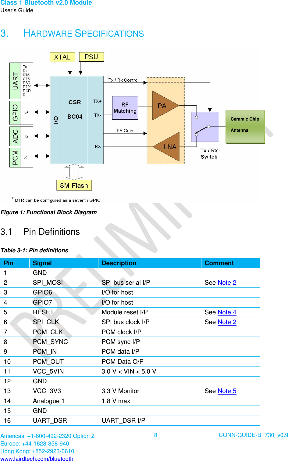
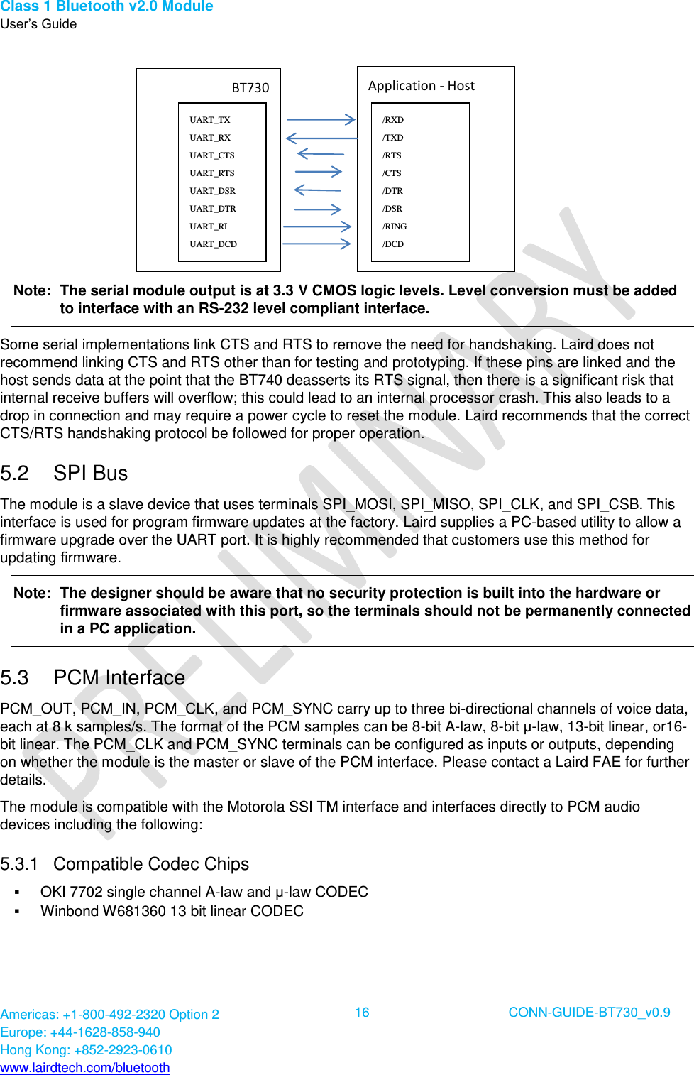
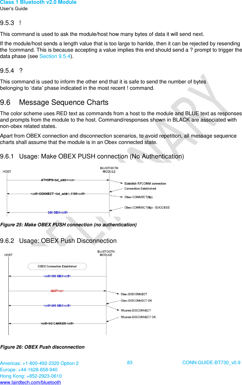
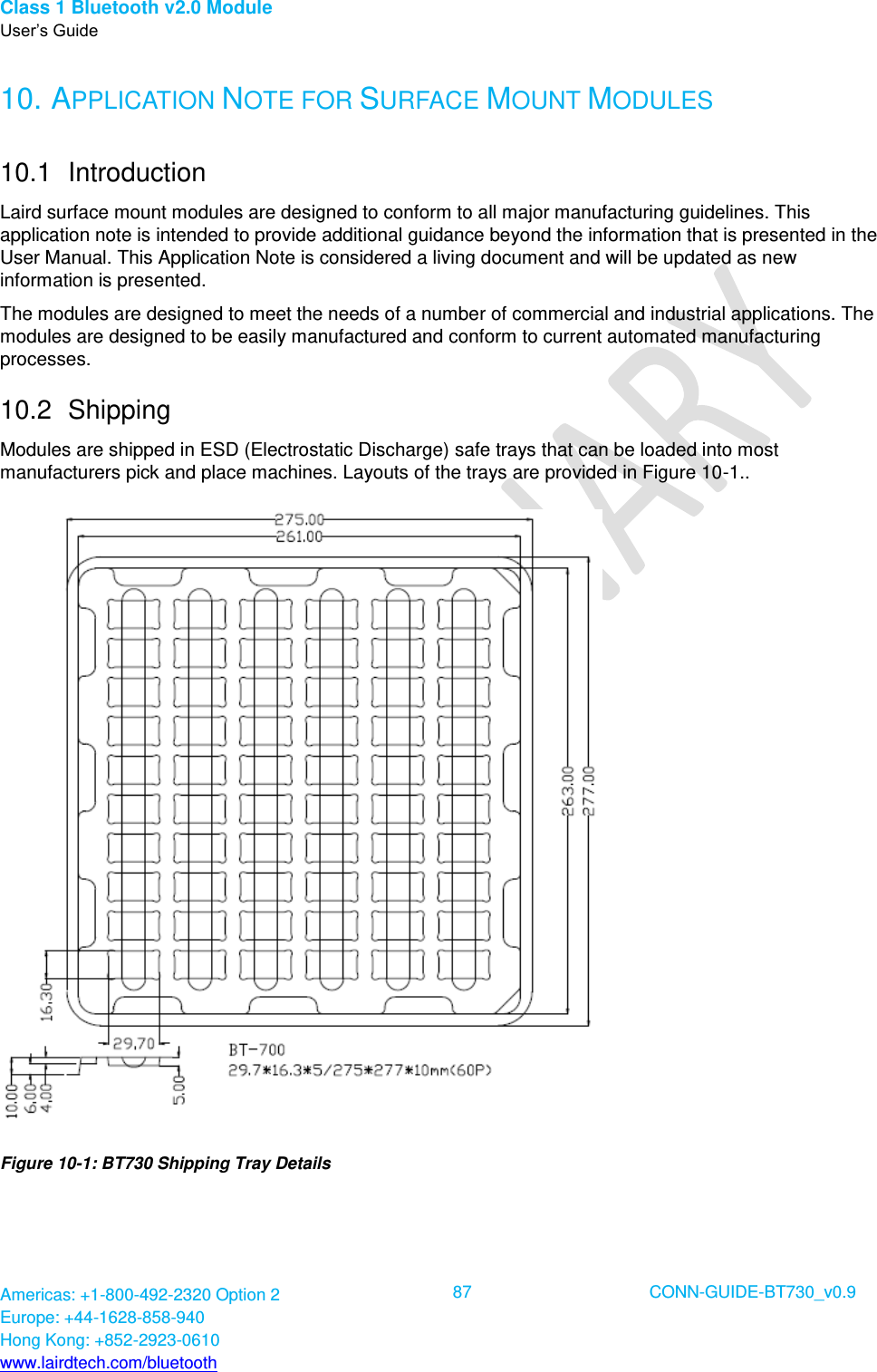
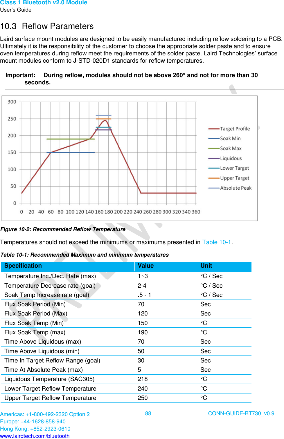
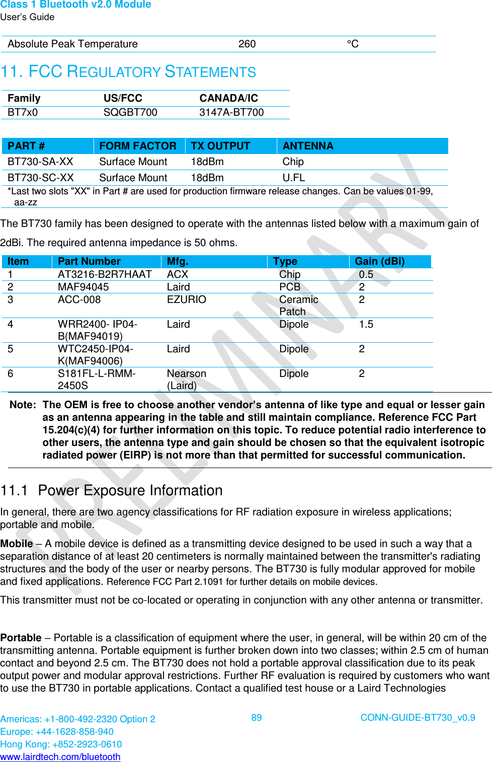
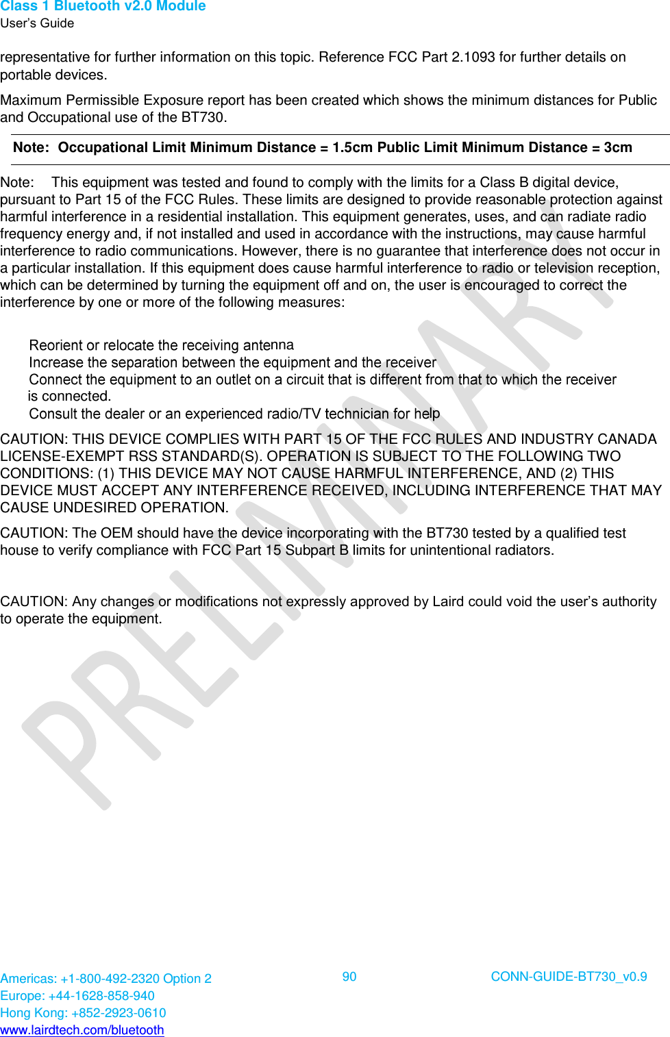
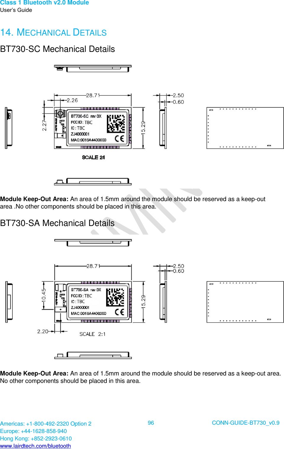
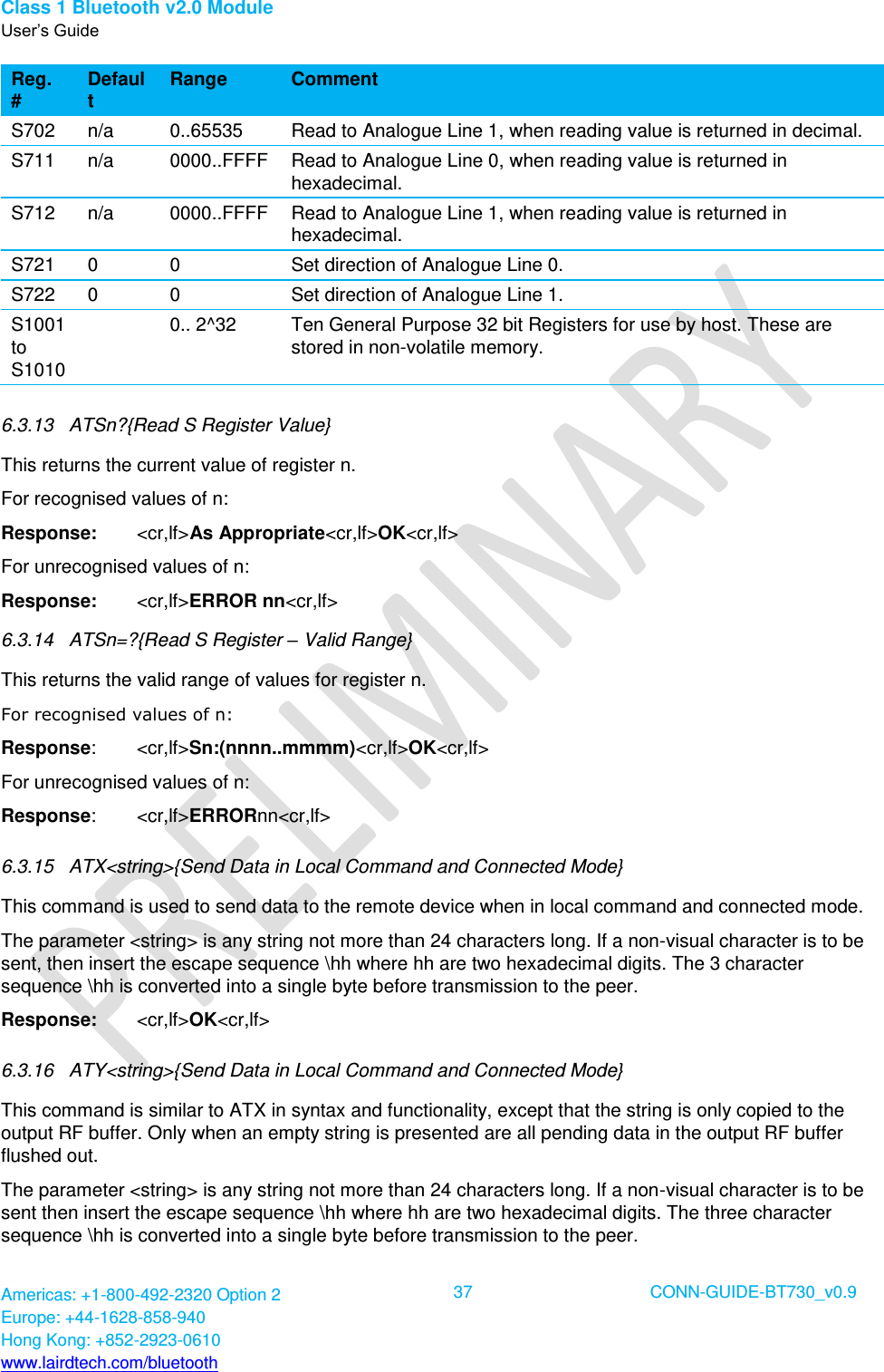
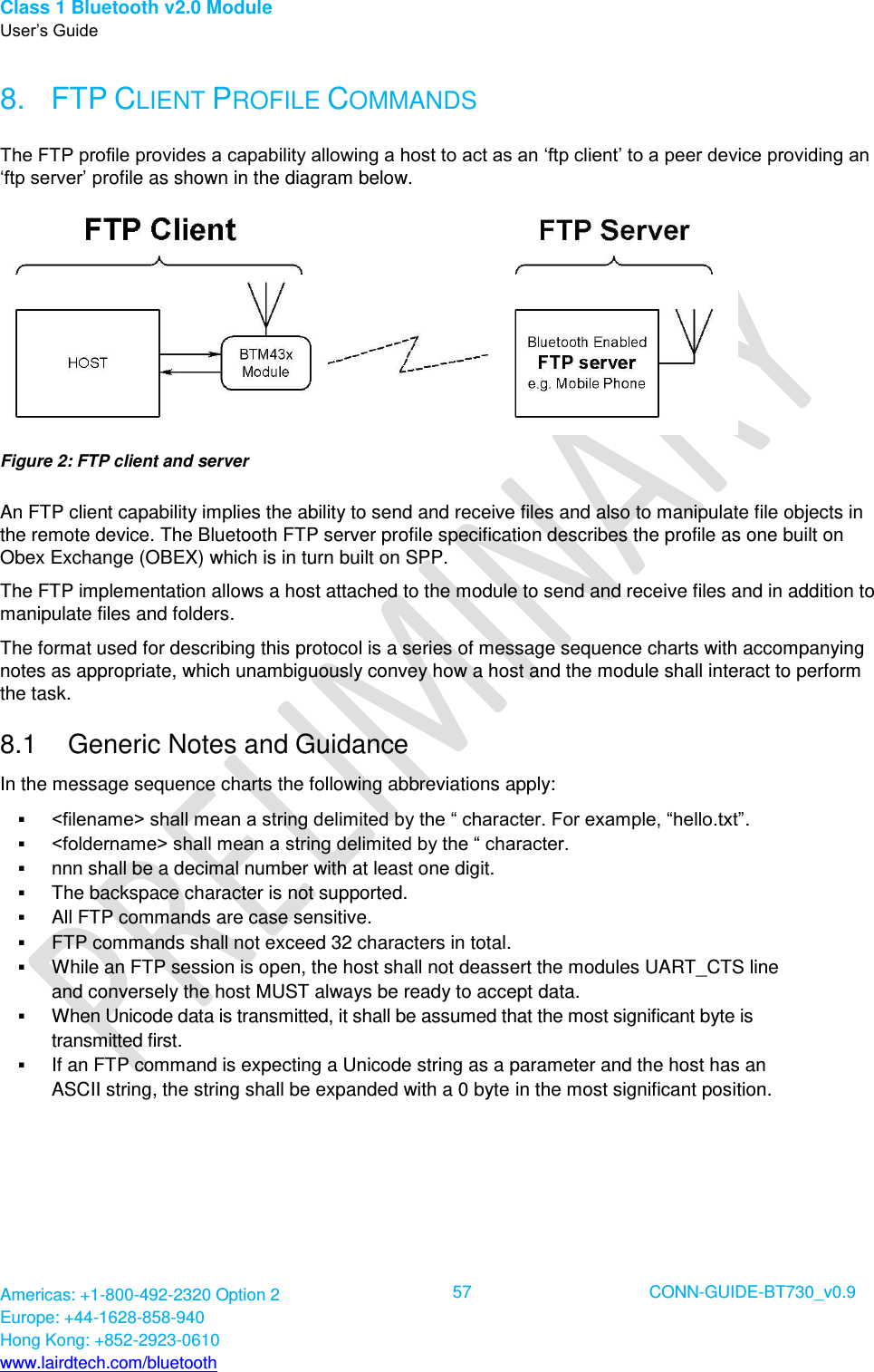
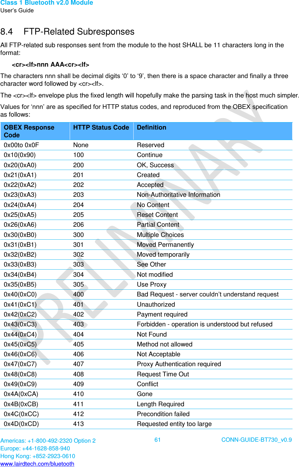
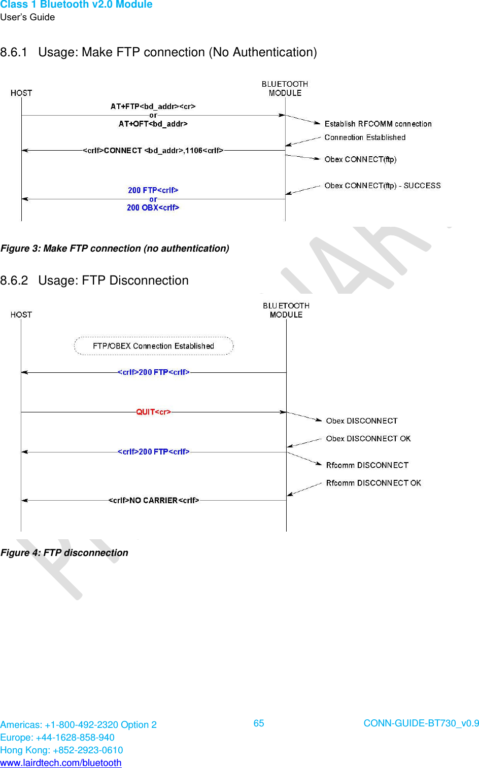
![Class 1 Bluetooth v2.0 Module User’s Guide Americas: +1-800-492-2320 Option 2 Europe: +44-1628-858-940 Hong Kong: +852-2923-0610 www.lairdtech.com/bluetooth 17 CONN-GUIDE-BT730_v0.9 5.4 General Purpose I/O and ADC 5.4.1 GPIO Seven lines of programmable bi-directional input/outputs (I/O) are provided that can be accessed either via the UART port, or Over The Air (OTA) from a second Bluetooth unit. These can be used as data inputs or to control external equipment. By using these in OTA mode, a BT730 module can be used for control and data acquisition without the need for any additional host processor. Each of the GPIO[3:9] ports can be independently configured to be either an input or output. A selection of ports can be accessed synchronously. The ports are powered from VCC. The mode of these lines can be configured and the lines are accessed via S Registers 623 to 629. 5.4.2 ADC The BT730 provides access to two 8-bit ADCs (Analogue 0 and 1). These provide an input range of 0 mV to 1,800 mV, which can be read using the S registers 701 and 702. Suitable external scaling and over-voltage protection should be incorporated in your design. The module provides five samples per second at the UART with a baud rate of 115,200 or above. 6. AT COMMAND SET REFERENCE 6.1 Introduction This document describes the protocol used to control and configure the following Laird Technologies Bluetooth devices: BT730-SA BT730-SC The protocol is similar to the industry standard Hayes AT protocol used in telephony modems which is appropriate for cable replacement scenarios, as both types of devices are connection oriented. The telephony commands have been extended to make the Laird device perform the two core actions of a Bluetooth device, which is make/break a connection and Inquiry. Other AT commands are also provided to perform ancillary functions, such as pairing, trusted device database management, and S register maintenance. Similar to telephony modems, the Laird device powers up in an unconnected state and only responds via the serial interface. In this state, the Laird device does not respond to Bluetooth inquiries. Then, just like controlling a modem, the host can issue AT commands which map to various Bluetooth activities. The command set is extensive enough to allow a host to make connections which are authenticated and/or encrypted or not authenticated and/or encrypted or any combination of these. Commands can be saved, so that on a subsequent power-up the device is discoverable or automatically connects. The device has a serial interface which can be configured for baud rates from 1200 up to 921600 and an RF communications end point. The latter has a concept of connected and unconnected modes and the former has a concept of command and data modes. This leads to the matrix of states shown in Table 6-1.](https://usermanual.wiki/Laird-Connectivity/BT700.user-manual-BT730-series/User-Guide-1969495-Page-17.png)
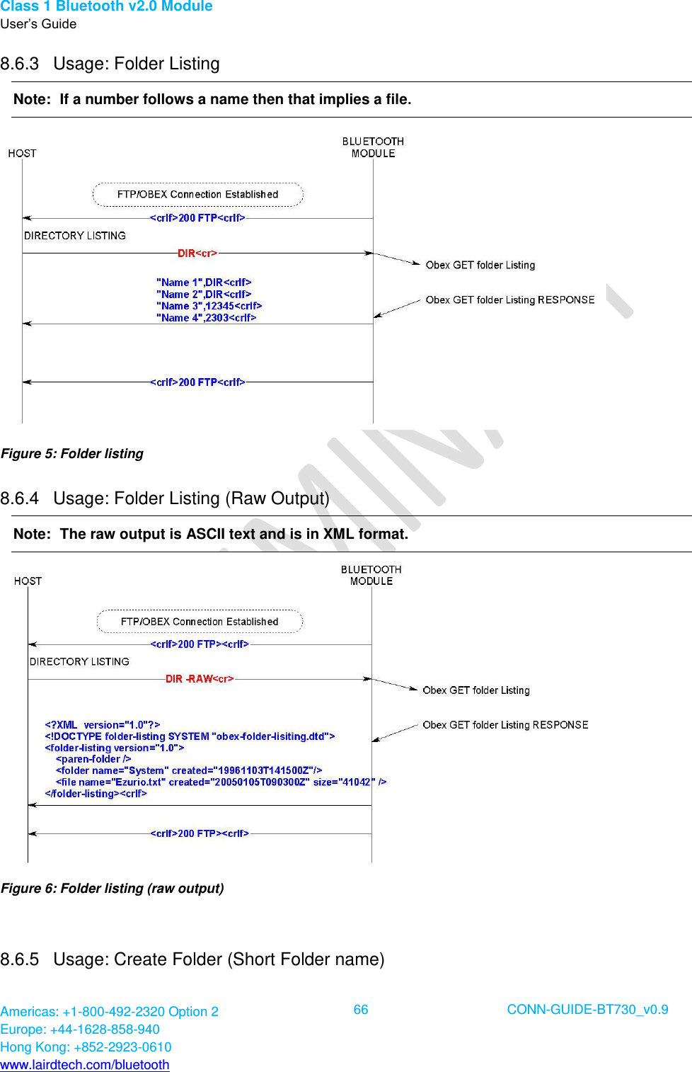
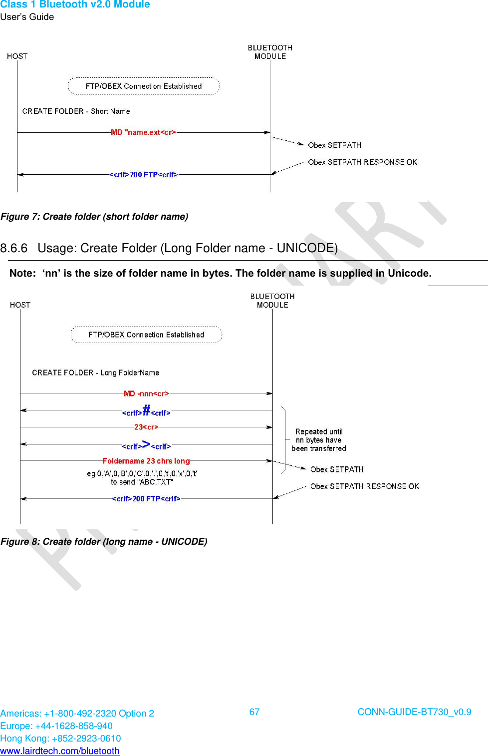
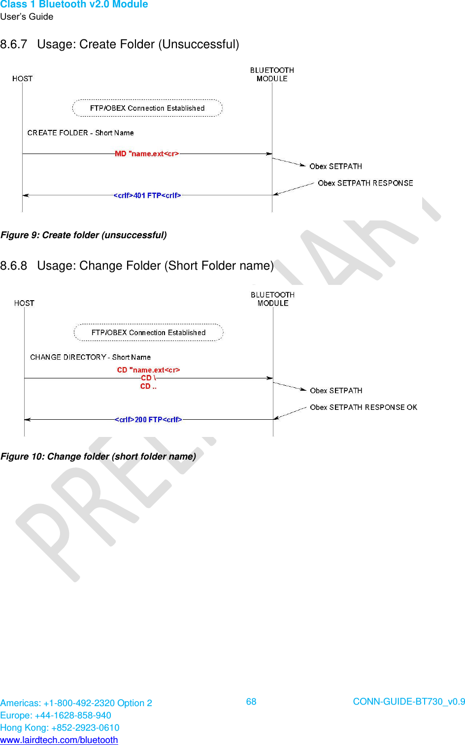
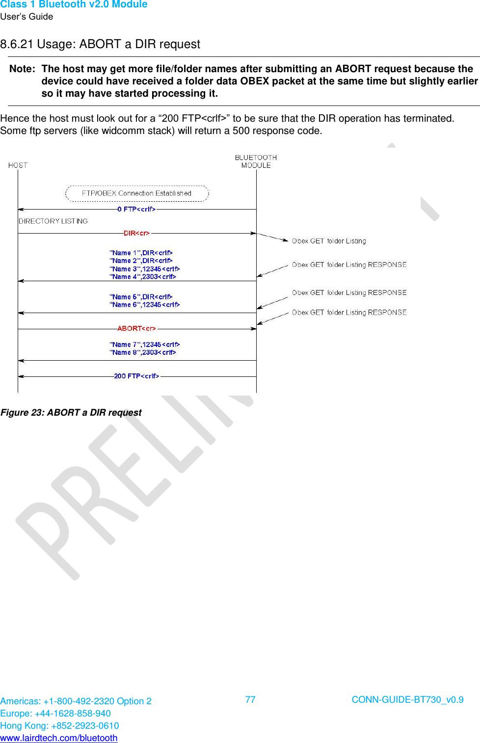
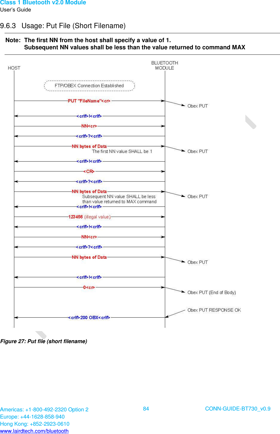
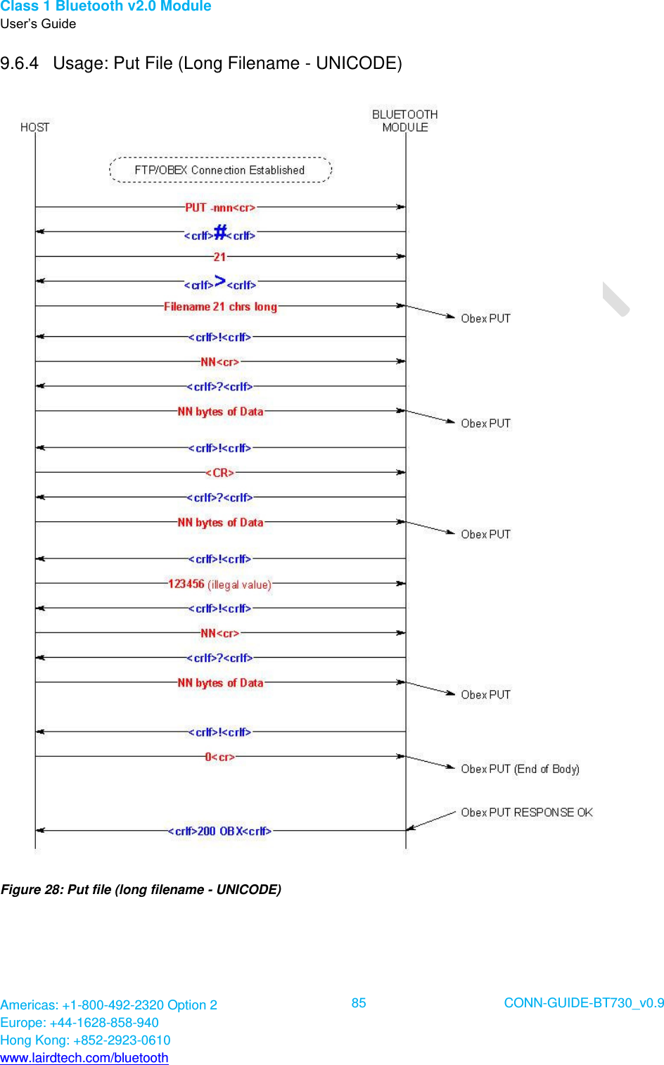
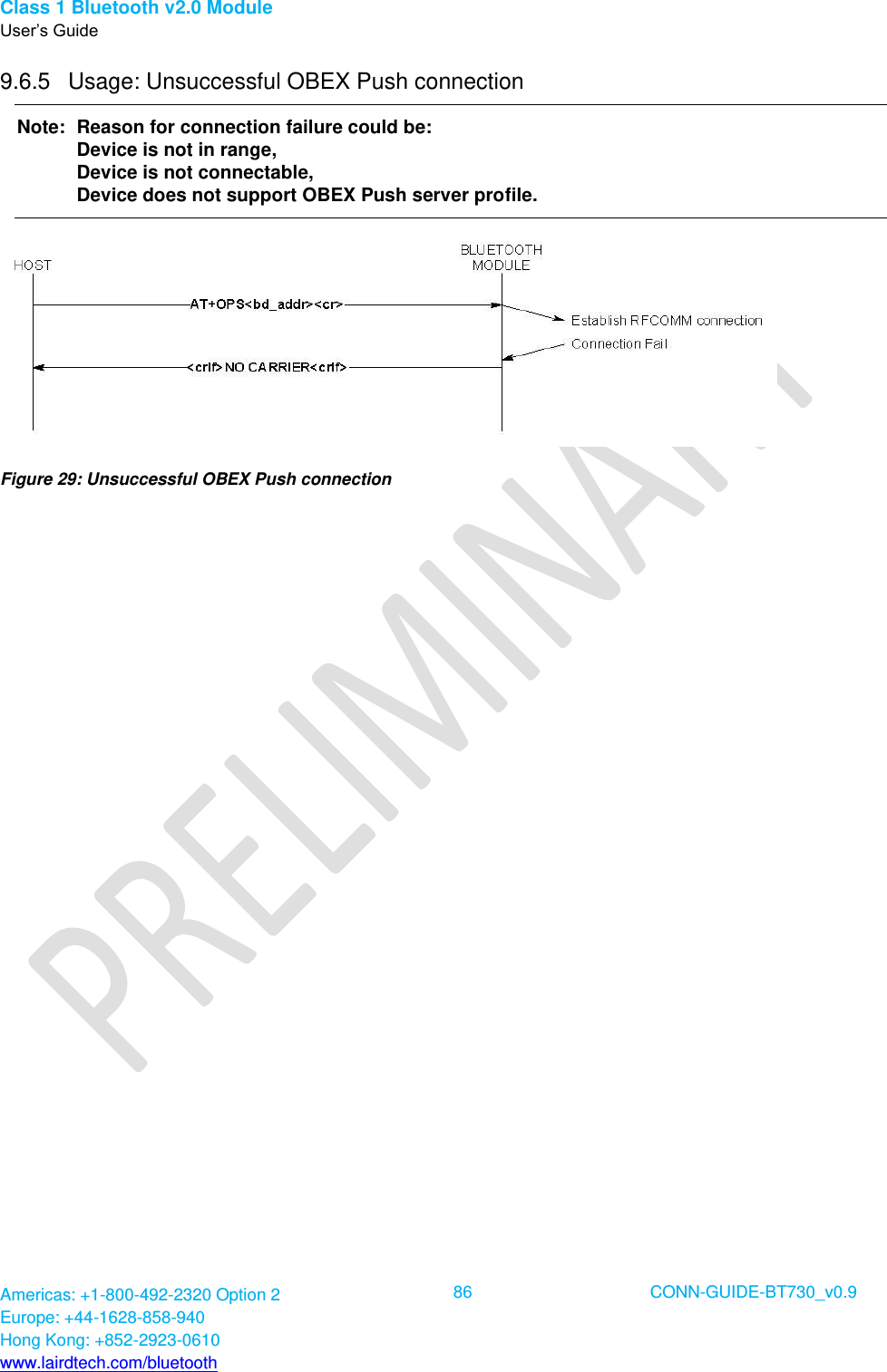
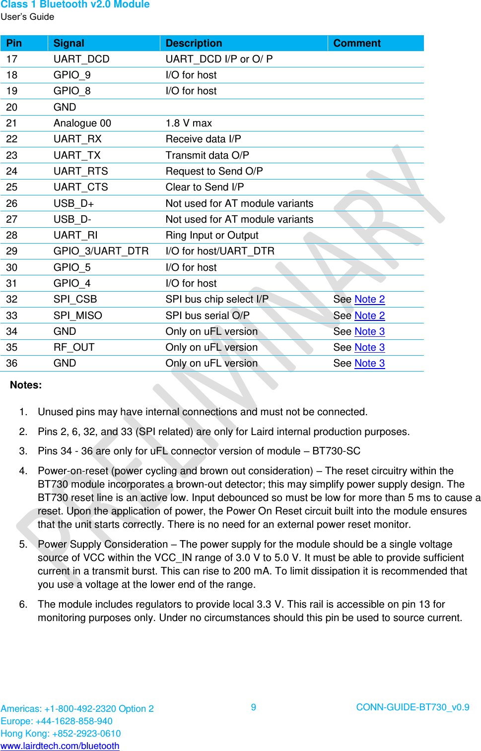
![Class 1 Bluetooth v2.0 Module User’s Guide Americas: +1-800-492-2320 Option 2 Europe: +44-1628-858-940 Hong Kong: +852-2923-0610 www.lairdtech.com/bluetooth 78 CONN-GUIDE-BT730_v0.9 9. OBEX PROFILE COMMANDS This section describes the OBEX implementation on BTM430/431 which allows performing the role of ‘Obex Push Client’ as illustrated in the diagram below. Figure 24: OBEX Push client and server The Obex Push profile implementation provides the capability to a host to act as an ‘Obex Push client’ to a peer device providing an ‘obex push server’ profile. An Obex Push client capability implies the ability to send and optionally receive a default file. The Bluetooth Obex Push server profile specification describes the profile as one built on Obex Exchange (OBEX) which is in turn built on SPP. The Object Push Profile [3] describes the profile as having the three following features: Object Push – Mandatory Business Card Pull – Optional Business Card Exchange – Optional This implementation only offers the Mandatory Object Push feature. The implementation on BTM430/431 allows a host attached to the module to send and receive files and to manipulate files and folders. The format used in this document for describing this protocol is a series of message sequence charts with accompanying notes as appropriate, which unambiguously convey how a host and the module shall interact to perform the task. 9.1 Generic Notes and Guidance In the message sequence charts the following abbreviations apply: <crlf> shall mean a two character sequence made up of the ASCII characters 0x0D (carriage return) and 0x0A (line feed). <cr> shall mean a one character sequence made up of the ASCII character 0x0D. <lf> shall mean a one character sequence made up of the ASCII character 0x0A. <bd_addr> shall mean a 12 digit string consisting of only hexadecimal digits 0-9, A-F, and a-f. <filename> shall mean a string delimited by the “ character. For example, “hello.txt”. <foldername> shall mean a string delimited by the “ character.](https://usermanual.wiki/Laird-Connectivity/BT700.user-manual-BT730-series/User-Guide-1969495-Page-78.png)