Laird Connectivity BT700 Class 1 Bluetooth Data Module User Manual BT740 series
Laird Technologies Class 1 Bluetooth Data Module BT740 series
UserManual.wiki
>
Laird Connectivity
>
BT700 User Manual
>
user manual (BT740 series)
Contents
1.
user manual (BT730 series)
2.
user manual (BT740 series)
user manual (BT740 series)
Navigation menu
Upload a User Manual
Namespaces
Wiki Guide
HTML
PDF
Info
Views
User Manual
Discussion / Help
Navigation
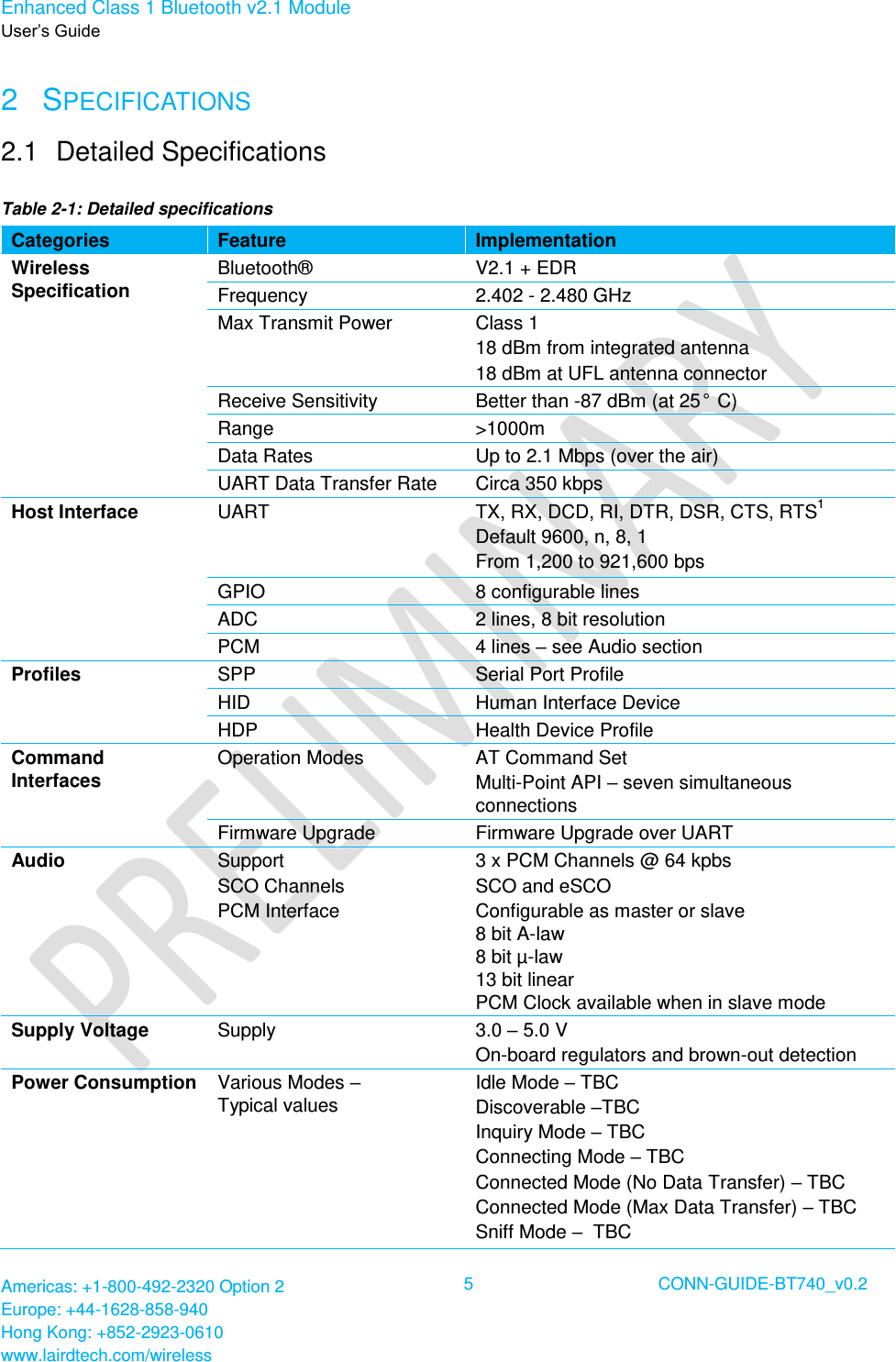
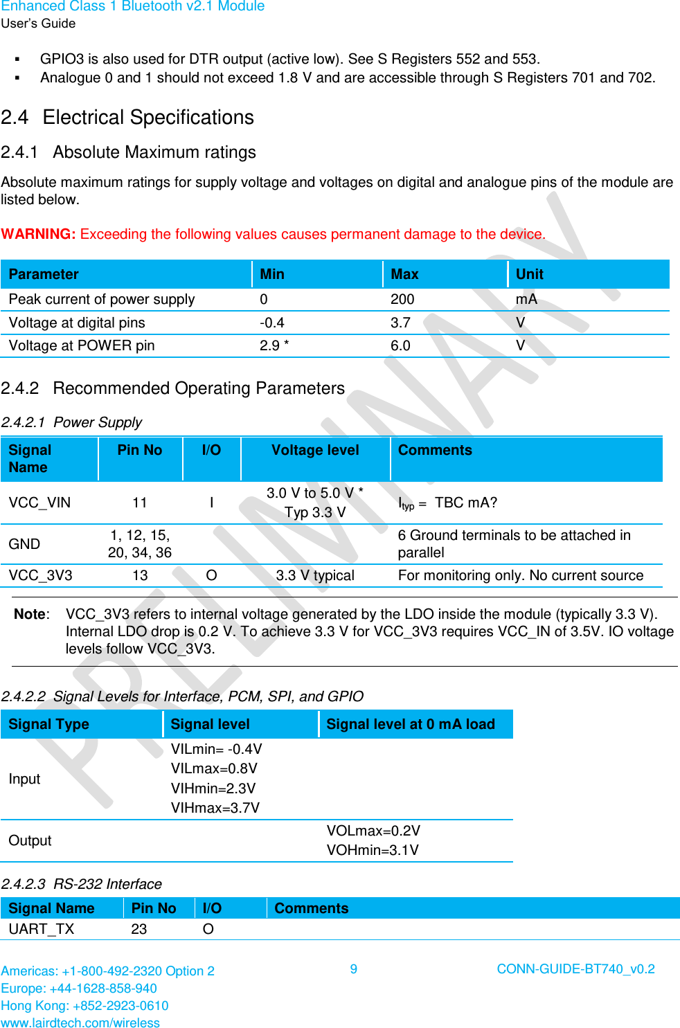
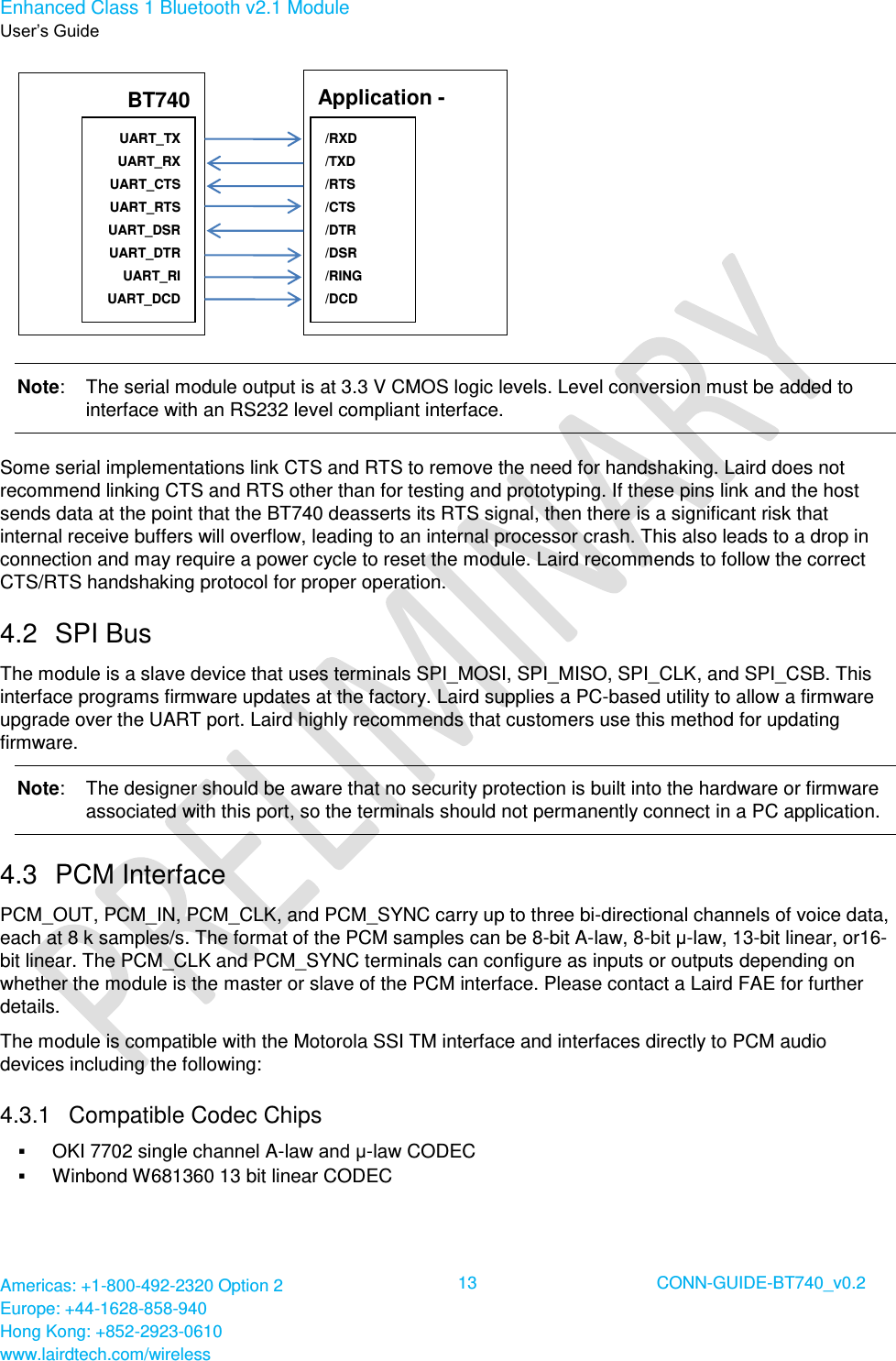
![Enhanced Class 1 Bluetooth v2.1 Module User’s Guide Americas: +1-800-492-2320 Option 2 Europe: +44-1628-858-940 Hong Kong: +852-2923-0610 www.lairdtech.com/wireless 14 CONN-GUIDE-BT740_v0.2 4.4 General Purpose I/O and ADC 4.4.1 GPIO Laird provides seven lines of programmable bi-directional input/outputs (I/O) that can be accessed either via the UART port or Over The Air (OTA) from a second Bluetooth unit. These can be used as data inputs or to control external equipment. By using these in OTA mode, a BT730 module can be used for control and data acquisition without the need for any additional host processor. Each of the GPIO[3:9] ports can independently configure to be either an input or output. A selection of ports can be accessed synchronously. The ports power from VCC. The mode of these lines can be configured and the lines are accessed via S Registers 623 to 629. 4.4.2 ADC The BT740 provides access to two 8-bit ADCs (Analogue 0 and 1). These provide an input range of 0 mV to 1,800 mV, which are read using the S registers 701 and 702. Suitable external scaling and over-voltage protection should be incorporated in your design. The module provides five samples per second at the UART with a baud rate of 115,200 or above.](https://usermanual.wiki/Laird-Connectivity/BT700.user-manual-BT740-series/User-Guide-1969496-Page-14.png)
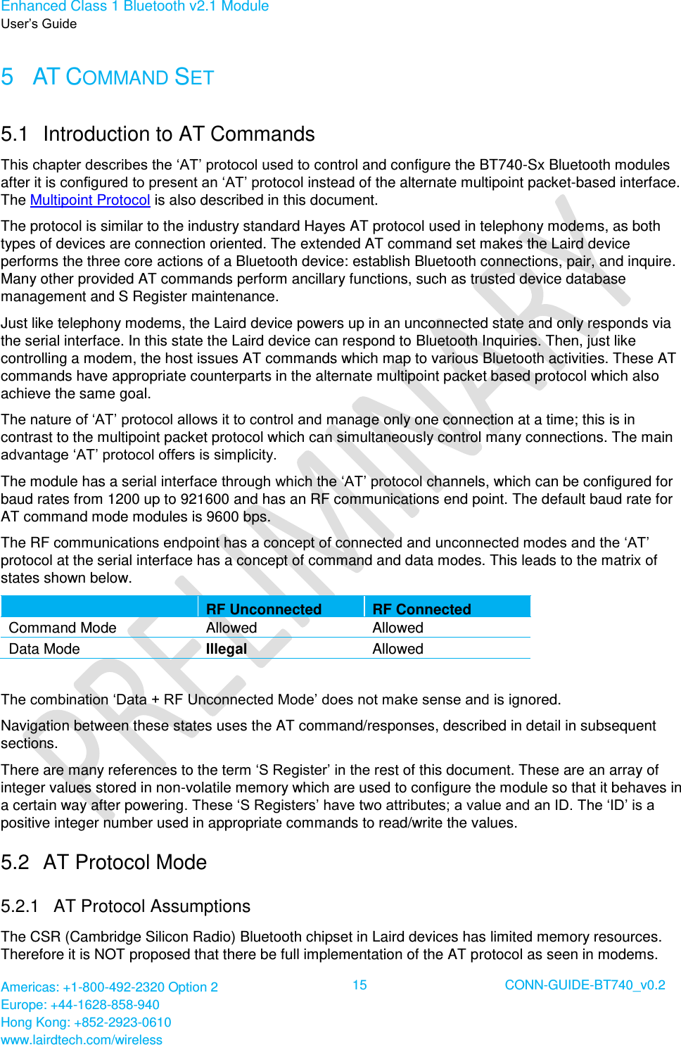
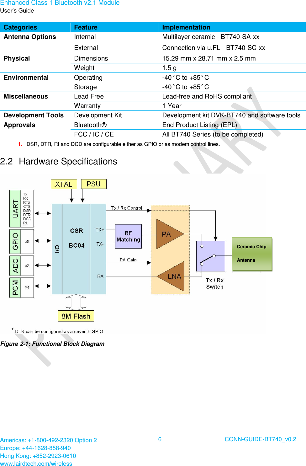
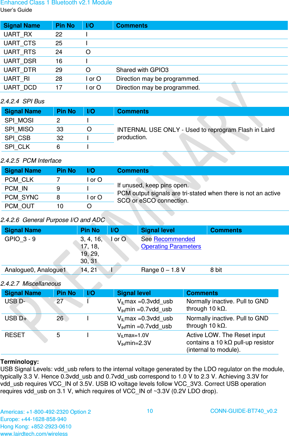
![Enhanced Class 1 Bluetooth v2.1 Module User’s Guide Americas: +1-800-492-2320 Option 2 Europe: +44-1628-858-940 Hong Kong: +852-2923-0610 www.lairdtech.com/wireless 30 CONN-GUIDE-BT740_v0.2 5.3.44 HDP: Endpoint Definition In SDP Record Command: AT+HAE,iiii,”endpointname” Response: <cr,lf>OK<cr,lf> Or <cr,lf>ERROR nn<cr,lf> Description: This is a Health Device Profile (HDP Agent related command. Refer to Application Examples for details). Please note ERROR 59 implies that the profile has not been activated which means bit 2 in S Reg 9003 is not set AND S Reg 9070 is not 0. It inserts details in the SDP record. 5.3.45 HDP: Read Attribute Value In Agent Command: AT+HAGhhhh,aaaa,ssss Response: <cr,lf>OK<cr,lf> Or <cr,lf>ERROR nn<cr,lf> Description: This is a Health Device Profile (HDP Agent related command. Refer to Application Examples for details). Please note ERROR 59 implies that the profile has not been activated which means bit 2 in S Reg 9003 is not set AND S Reg 9070 is not 0. 5.3.46 HDP: Activate SDP Record For Agent Command: AT+HAL Response: <cr,lf>OK<cr,lf> Or <cr,lf>ERROR nn<cr,lf> Description: This is a Health Device Profile (HDP Agent related command. Refer to Application Examples for details). Please note ERROR 59 implies that the profile has not been activated which means bit 2 in S Reg 9003 is not set AND S Reg 9070 is not 0. 5.3.47 HDP: Trigger Agent Scan Report Command: AT+HARhhhh,pppp[,aaaa[,aaaa[…]]] Response: <cr,lf>OK<cr,lf> Or <cr,lf>ERROR nn<cr,lf> Description: This is a Health Device Profile (HDP Agent related command. Refer to Application Examples for details). Please note ERROR 59 implies that the profile has not been activated which means bit 2 in S Reg 9003 is not set AND S Reg 9070 is not 0.](https://usermanual.wiki/Laird-Connectivity/BT700.user-manual-BT740-series/User-Guide-1969496-Page-30.png)
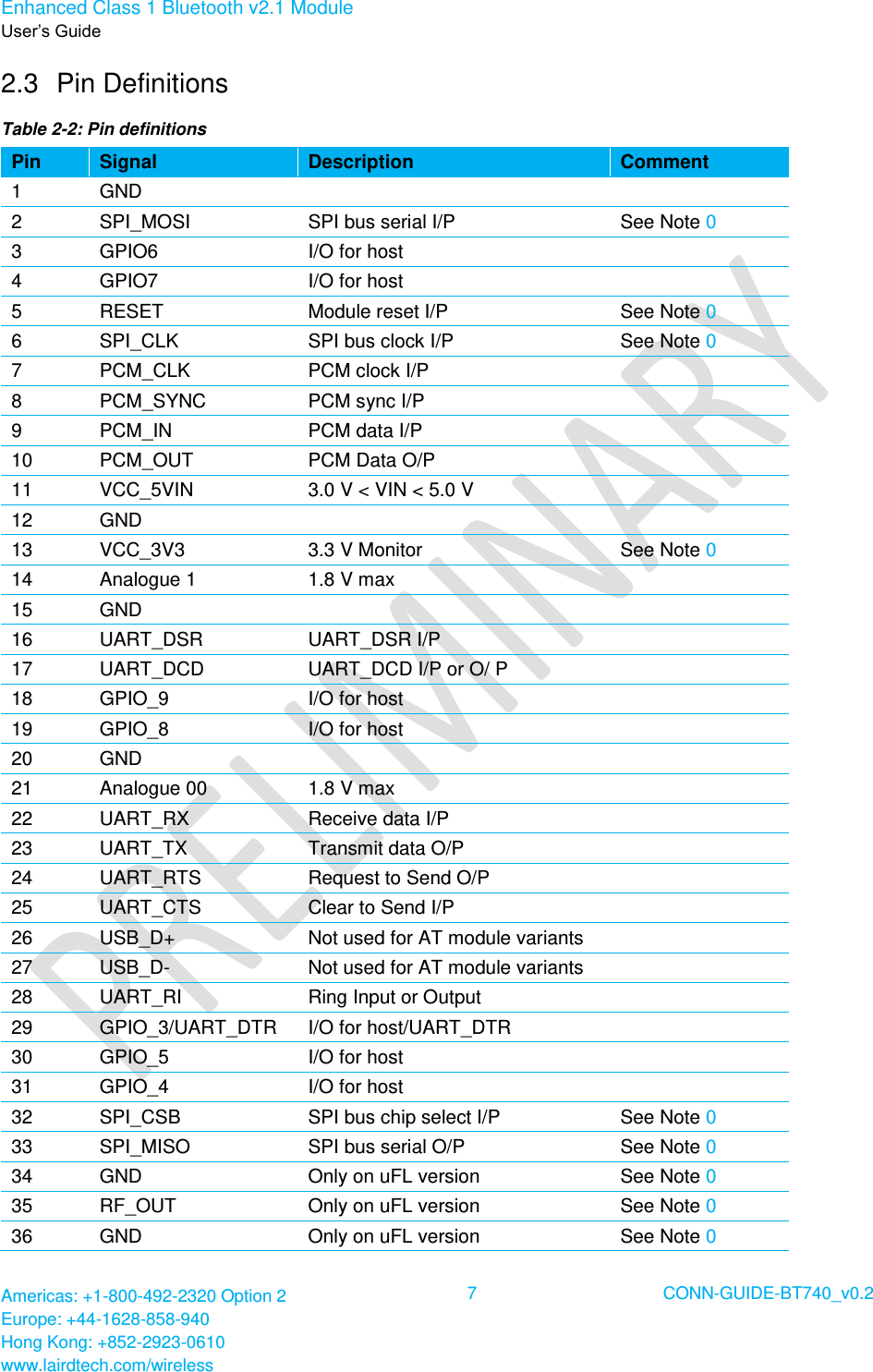
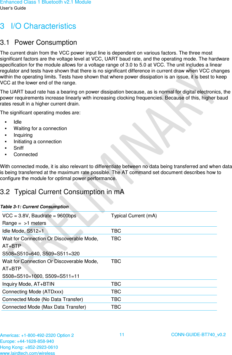
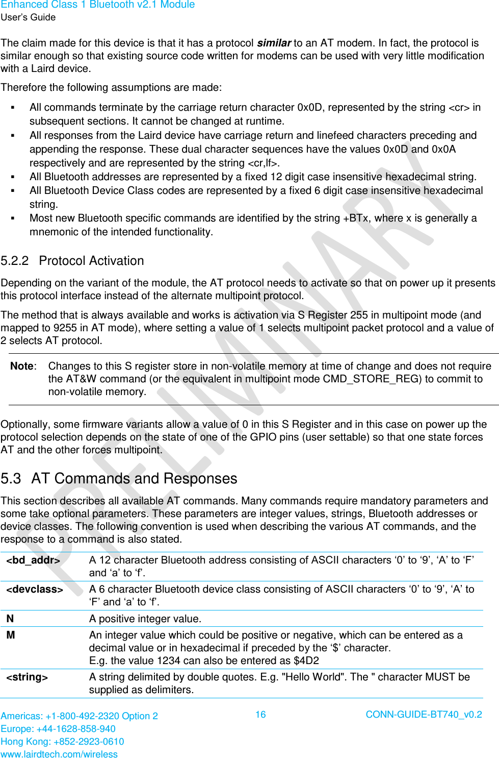
![Enhanced Class 1 Bluetooth v2.1 Module User’s Guide Americas: +1-800-492-2320 Option 2 Europe: +44-1628-858-940 Hong Kong: +852-2923-0610 www.lairdtech.com/wireless 33 CONN-GUIDE-BT740_v0.2 5.3.56 Unsolicited/Async Responses The ‘AT’ Protocol is a command/response type of protocol. This means that the Laird device normally only responds to AT commands and in addition only responds to one AT command at a time. Under special circumstances, unsolicited responses send to the host. They are described in the following subsections. Each unsolicited response is prefixed and postfixed by a cr,lf two character sequence. Command: No Command. This is a status message. Response: RING Description: This string sends to the host every second repeatedly when a remote device initiates a serial port connection. The fully qualified string is in the form RING 012345678901, where 012345678901 is a 12 digit hexadecimal number which corresponds to the remote device’s Bluetooth address. The host responds with the ATA command to accept the connection or reject it using the ATH command. If S Register 0 is set to a non-zero value then the incoming SPP connection automatically accepts after the number of RINGS specified in S Register 0 sends to the host. Only incoming SPP connections invoke a RING response. Connections on other profiles automatically accepts. Command: No Command. This is a status message. Response: PIN ? <bd_addr> Description: This response sends to the host during a legacy pairing negotiation (pre BT version 2.1 compliant devices). The fully qualified string is PIN? 012345678901, where 012345678901is the Bluetooth address of the peer device. In response, the host must supply a pin code using the AT+BTK command. Command: No Command. This is a status message. Response: PASSKEY ? N <bd_addr>[,passcode] Description: This response sends to the host during a simple secure pairing (SSP) negotiation and when the module is configured appropriately via S Register 9006. Where N is 1 for the host to display the passkey supplied, 2 for the host to respond with either the command AT+BTKY or AT+BTKN and 3 for the host to respond with AT+BTK=”nnnnnn”. The fully qualified string is : PASSKEY? 1 012345678901,123456 where 012345678901 is the Bluetooth address of the peer device and 123456 is the passcode to display to the user. PASSKEY? 2 012345678901,123456 where 012345678901 is the Bluetooth address of the peer device and 123456 is the passcode to display to the user. PASSKEY? 3 012345678901 where 012345678901 is the Bluetooth address of the peer device and the user echoes the passcode displayed on the peer device, or agree with the other user to enter the same random 6 digit passcode at both ends. Command: No Command. This is a status message. Response: PAIR N <bd_addr> Description: This response sends to the host on completion (success or otherwise) of a pairing process. If pairing succeeds then ‘n’ = 0; if a timeout occurs then ‘n’=1; and for all other unsuccessful outcomes the value is 2.](https://usermanual.wiki/Laird-Connectivity/BT700.user-manual-BT740-series/User-Guide-1969496-Page-33.png)
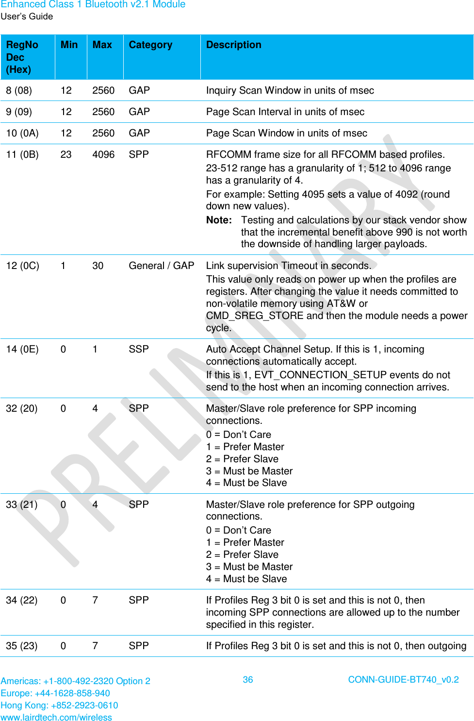
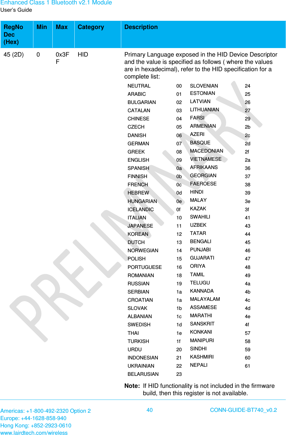
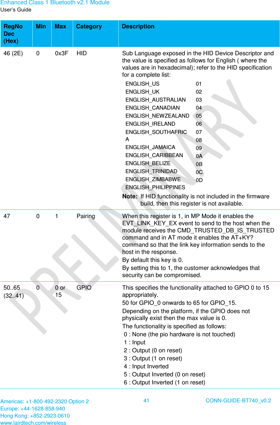
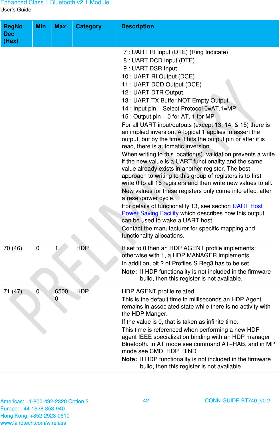
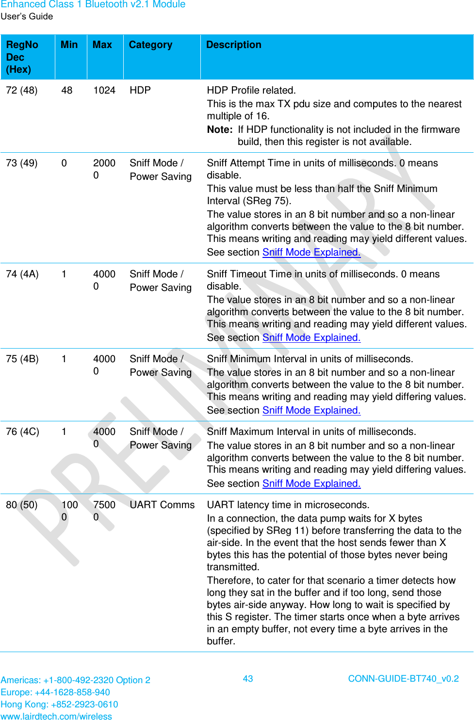
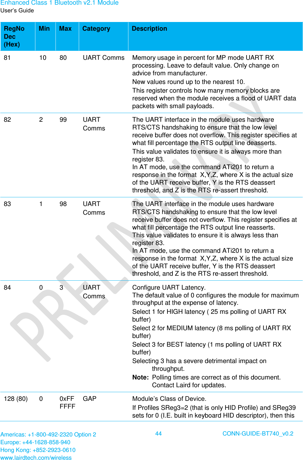
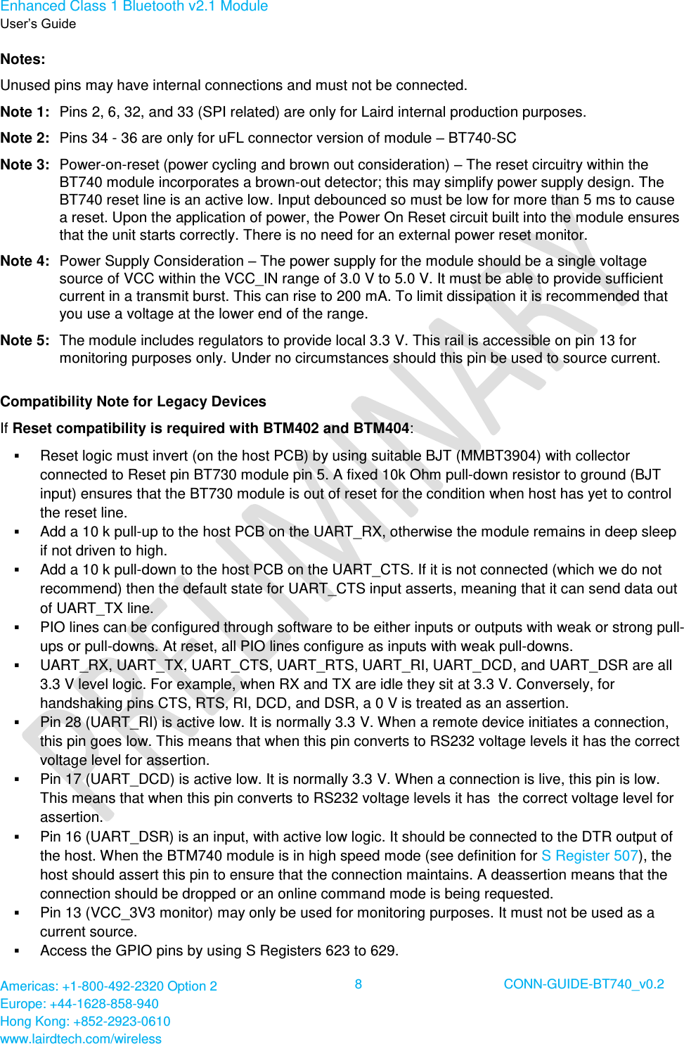
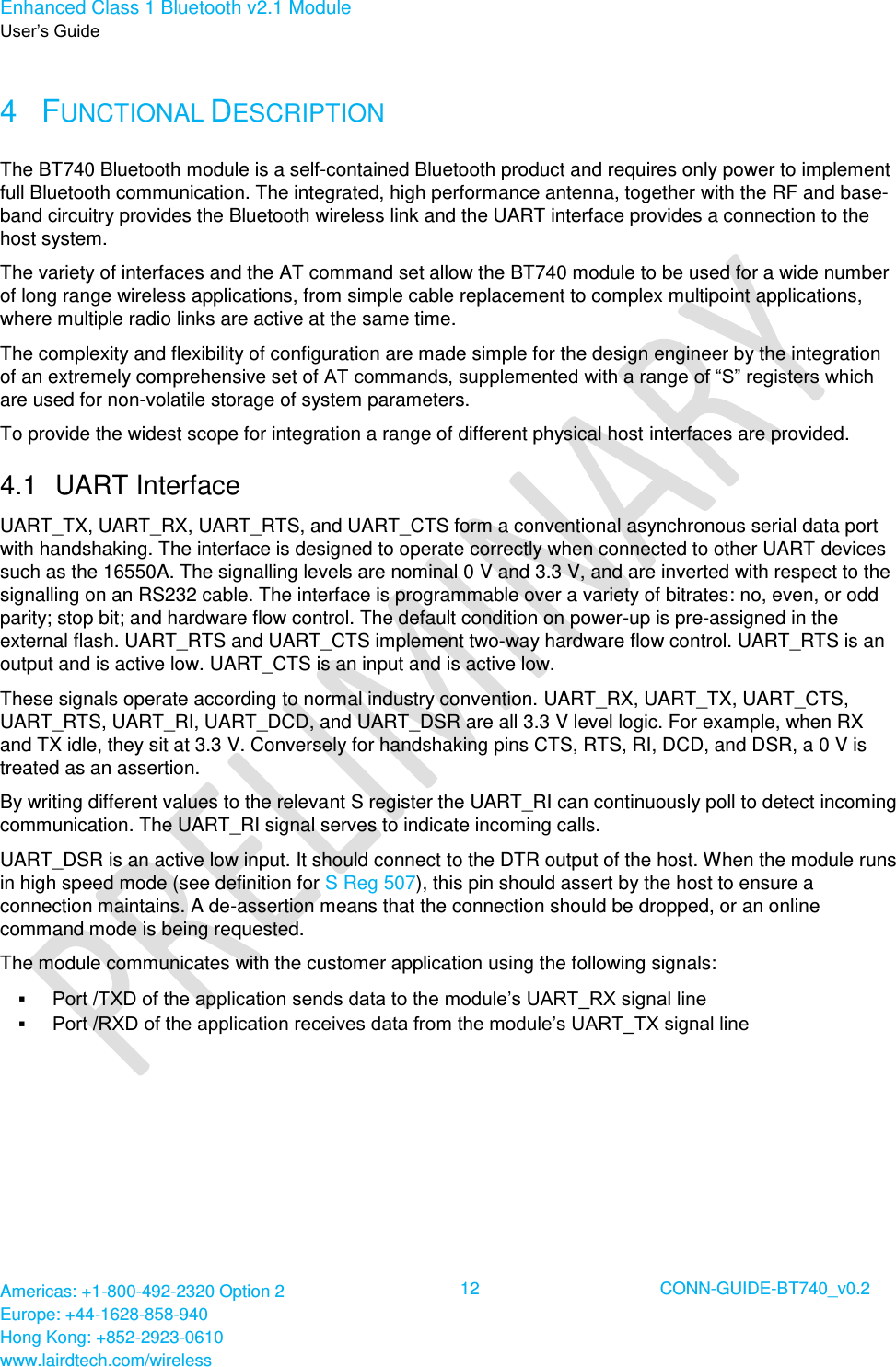
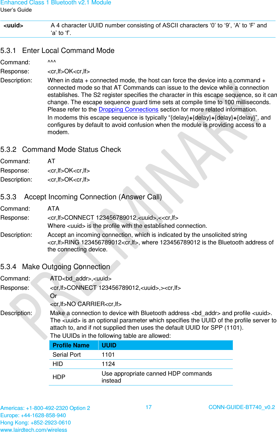
![Enhanced Class 1 Bluetooth v2.1 Module User’s Guide Americas: +1-800-492-2320 Option 2 Europe: +44-1628-858-940 Hong Kong: +852-2923-0610 www.lairdtech.com/wireless 45 CONN-GUIDE-BT740_v0.2 RegNo Dec (Hex) Min Max Category Description class of device is overridden with a value which specifies a HID keyboard device. Note: Most registers read by the firmware at reset. Hence the radio requires a reset after setting a register for it to be effective. This means the relevant S Register set MUST commit to non-volatile memory before initiating a reset. The S Registers store to non-volatile memory using the command [CMD_STORE_SREG].](https://usermanual.wiki/Laird-Connectivity/BT700.user-manual-BT740-series/User-Guide-1969496-Page-45.png)
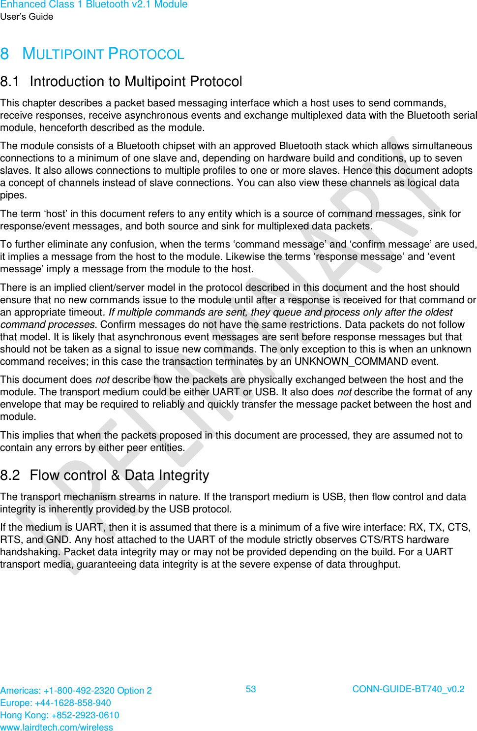
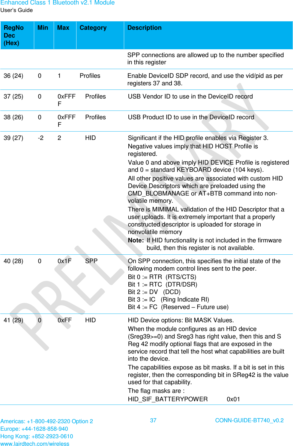
![Enhanced Class 1 Bluetooth v2.1 Module User’s Guide Americas: +1-800-492-2320 Option 2 Europe: +44-1628-858-940 Hong Kong: +852-2923-0610 www.lairdtech.com/wireless 54 CONN-GUIDE-BT740_v0.2 8.3 Packet Format This section describes the general format of incoming and outgoing packets. The term ‘incoming’ henceforth implies packets sent by the host to the module and ‘outgoing’ in the reverse direction. That is, the direction terminology is module (server) centric. All packets have octet granularity. When an octet is described as containing bit fields, it shall be taken that bit 0 is the least significant bit and bit 7 is the most significant bit. Subfields in the packet which require multiple octets shall be ordered so that the lowest significant octet transmits LAST over the transport media, unless specifically described otherwise – this is also referred to as Big Endien format. For example, a 16-bit word value requires two octets within the packet and the first transmitted octet corresponds to the upper byte. Similarly, a 6-byte Bluetooth address transports the most significant byte first. If the order is reversed then it is specifically highlighted in the description of appropriate packets. Subfields which are data arrays shall be described with the ‘[ ]’ operator in descriptions which come in subsequent chapters. Apart from data packets, all command, confirm, respond and event packets are of fixed size. If there isn’t enough data to fill a packet, then the packet fills with 0s. The protocol and fixed packet format is optimized to ensure maximum data throughput over the air. Subsequent sections describe the packets in detail. 8.4 Host to Module Packets These are packets used to convey commands and confirms to the module or raw data to be sent over an open Bluetooth connection. 8.5 Command & Confirm Packets The format for command and confirm packets is displayed in Table 8-1. Table 8-1: Command and confirm packets Octet Field Description 0 LENGTH Total length of this packet, including this octet 1 CHANNEL Always zero 2 CMD_ID/CNF_ID Described in the subsequent chapters and have CMD_ or CNF_ prefixes 3 FLOW_IN Bit 0 to 6 specify a mask. A clear bit means the module should NOT send any more packets to that corresponding SPP data channel. Bit 7 is always zero and is used as an extension bit in the future. It is assumed that the host is always able to receive a response or status packet. 4..N DATA[] Data as required and has meaning specific to CMD_ID or CNF_ID. For example, if the command is to make a connection to a peer device, then it is at least a six octet array specifying the Bluetooth address of the peer. The value of CMD_ID is in the range of 0 to 63 and commands are queued until a previous command is completed by sending a response packet to the host.](https://usermanual.wiki/Laird-Connectivity/BT700.user-manual-BT740-series/User-Guide-1969496-Page-54.png)
![Enhanced Class 1 Bluetooth v2.1 Module User’s Guide Americas: +1-800-492-2320 Option 2 Europe: +44-1628-858-940 Hong Kong: +852-2923-0610 www.lairdtech.com/wireless 56 CONN-GUIDE-BT740_v0.2 Unknown command values result in an EVT_UNKNOWN_COMMAND event, with the command value reflected in the data field. If the octet value is specified in the range 128 to 255 (0x80 to 0xFF), then reflecting that value in the data field of an EVT_UNKNOWN_COMMAND instead of the COMMAND field of a response packet guarantees that the packet is NOT mistakenly processed as an event. Confirm packets are not queued by the UART packet processor in the module and are processed as soon they are received. As an example, this allows passkeys and pincodes to submit to the module while a response is awaited by the CMD_CONNECTION_MAKE command. In other words, confirm packets always go to the head of the packet queue. 8.6 Data Packets The format for data packets is displayed in Table 8-2 and can arrive at any time; that is, they do not adhere to a client/server model. The only method by which the host can be stopped from sending this message is by sending a zero value in the FLOW_OUT field of a response or status message. The module is prepared to receive at least one data packet after deasserting the appropriate flow control bit. Table 8-2: Data packet format Octet Field Description 0 LENGTH Total length of this packet, including this octet 1 CHANNEL 0 is an invalid value as this marks the packet as command/response or event. 1 to 7 are dedicated serial port profile connections. 128 is dedicated as Hid Device data channel. All other channels are reserved for future use. 2..N DATA[] For channels 1 to 7, this data array unconditionally sends over the air in the appropriate. For channel 128 data is interpreted before appropriate HIT reports transmit. 8.7 Packet Processing Logic Data and Confirm packets process as soon as they are received. A command packet processes in a transaction, meaning it processes as soon as it is received if and only if there is no previous command processing and waiting for completion. Completion happens when an appropriate response packet is sent to the host. If a command transaction is currently in progress, then the packet inserts in a first-in, first-out queue. When an on-going command transaction completes, the queue is inspected and, if non-empty, the oldest queued command is processed. 8.7.1 Module to Host Packets These packets convey responses or events from the module and raw data received over an open Bluetooth connection or internal data source. Response packets are always a result of a command packet and event packets asynchronously send to the host as and when required. The host shall ensure that it is always ready to accept response and event packets, especially event packets as they can be sent at any time including where there is an incomplete transaction in progress.](https://usermanual.wiki/Laird-Connectivity/BT700.user-manual-BT740-series/User-Guide-1969496-Page-56.png)
![Enhanced Class 1 Bluetooth v2.1 Module User’s Guide Americas: +1-800-492-2320 Option 2 Europe: +44-1628-858-940 Hong Kong: +852-2923-0610 www.lairdtech.com/wireless 57 CONN-GUIDE-BT740_v0.2 8.7.2 Response Packets The format for response packets is displayed in Table 8-3. Table 8-3: Response packet format Octet Field Description 0 LENGTH Total length of this packet, including this octet 1 CHANNEL Always zero 2 CMD_ID Echoed from the command packet (Shall be > 0 and < 128) 3 FLOW_OUT Bit 0 to 6 specify a mask. A clear bit means the host should NOT send any more packets to that corresponding data channel. Bit 7 is always 0 and is an extension bit in the future. 4 STATUS Zero means success, otherwise see section “STATUS values” N..M DATA[] Data as required and has meaning specific to the response for CMD_ID 8.7.3 Event Packets The format for event packets is displayed in Table 8-4. Table 8-4: Event packet format Octet Field Description 0 LENGTH Total length of this packet, including this octet 1 CHANNEL Always zero 2 EVT_ID Described in subsequent chapters, but bit 7 is always set, hence >= 128 3 FLOW_OUT Bit 0 to 6 specify a mask. A clear bit means the host should NOT send any more packets to that corresponding data channel. Bit 7 is always zero and is an extension bit in the future. N..M DATA[] Data as required and has meaning specific to the response for EVT_ID The only difference between a response and an event packet is that octet 2 is defined as CMD_ID in the former and EVT_ID in the latter; in addition, the STATUS field is missing in the event packet. The value of CMD_ID will be in the range 0 to 0x3F and EVT_ID will take values in the range 0x80 to 0xFF. This allows bit 7 of that octet to be decoded whether the packet is a response packet or an event packet. The value of STATUS is in the range of 0 to 255. A value of zero means SUCCESS and any other value is a failure, where the value gives more details of the failure type. The values of STATUS are defined in a ‘C’ header file which can be obtained on request from Laird.](https://usermanual.wiki/Laird-Connectivity/BT700.user-manual-BT740-series/User-Guide-1969496-Page-57.png)
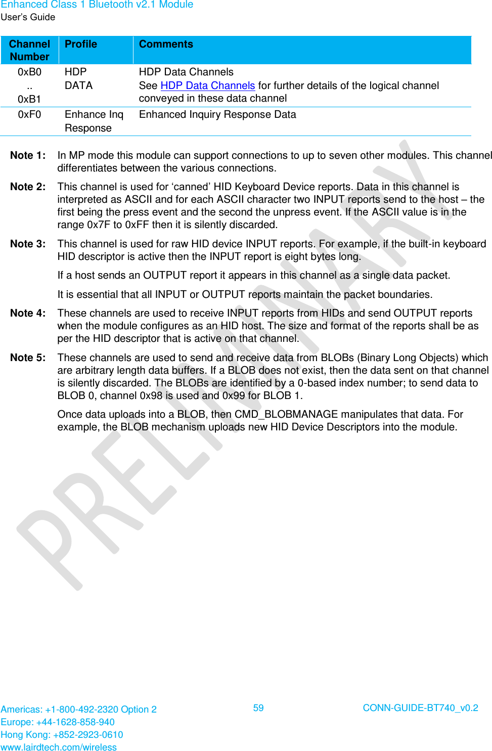
![Enhanced Class 1 Bluetooth v2.1 Module User’s Guide Americas: +1-800-492-2320 Option 2 Europe: +44-1628-858-940 Hong Kong: +852-2923-0610 www.lairdtech.com/wireless 58 CONN-GUIDE-BT740_v0.2 8.7.4 Data Packets The format for data packets is displayed in Table 8-5. The only method by which the host can stop the module from sending this message is by sending a zero value in the FLOW_IN field of command message, and even that is only for channels 1 to 7 inclusive. Table 8-5: Data packet format Octet Field Description 0 LENGTH Total length of this packet, including this octet 1 CHANNEL 0 is an invalid value as this marks the packet as command/response or event. The channel number is allocated as follows: 1 to 7 are dedicated serial port profile connections. 0x20, 0x80, 0x90..0x97,0xA0 are dedicated as HID data channels. 0x98..0x9F are dedicated for BLOB sending and receiving data from BLOBs. 0xB0 conveys HDP data and 0xB1 is a HDP continuation data channel. 0xF0 conveys Enhanced Inquiry Response Data to the host. All other channels are reserved for future use. 2..N DATA[] Data to be processed for channel CHANNEL. Data packets are symmetrical in format in both directions. Note: Only data channels 1 to 7 inclusive have flow control via the FLOW_IN and FLOW_OUT fields of command /confirm and response/event packets. 8.7.5 Data Channel Numbers Table 8-6 summarizes channel ID allocation for various connections and profiles. Table 8-6: Channel ID allocation Channel Number Profile Comments 0x0 - All traffic routed to/from the protocol parser –this is a command, confirm, or response packet 0x1 .. 0x7 SPP Serial Port profile data channels See Note 1 below 0x20 HID DEVICE Hid Device Channel – only one device allowed at a time See Note 2 below 0xA0 HID DEVICE Hid Device Channel – only one device allowed at a time See Note 3 below 0x90 .. 0x97 HID HOST Hid Host Channels – multiple connections to devices is possible See Note 4 below 0x98 .. 0x9F BLOB MANAGER Blob Manager Channels See Note 5 below 0xA0 HID DEVICE Hid Device Channel for sending and receiving raw HID reports.](https://usermanual.wiki/Laird-Connectivity/BT700.user-manual-BT740-series/User-Guide-1969496-Page-58.png)
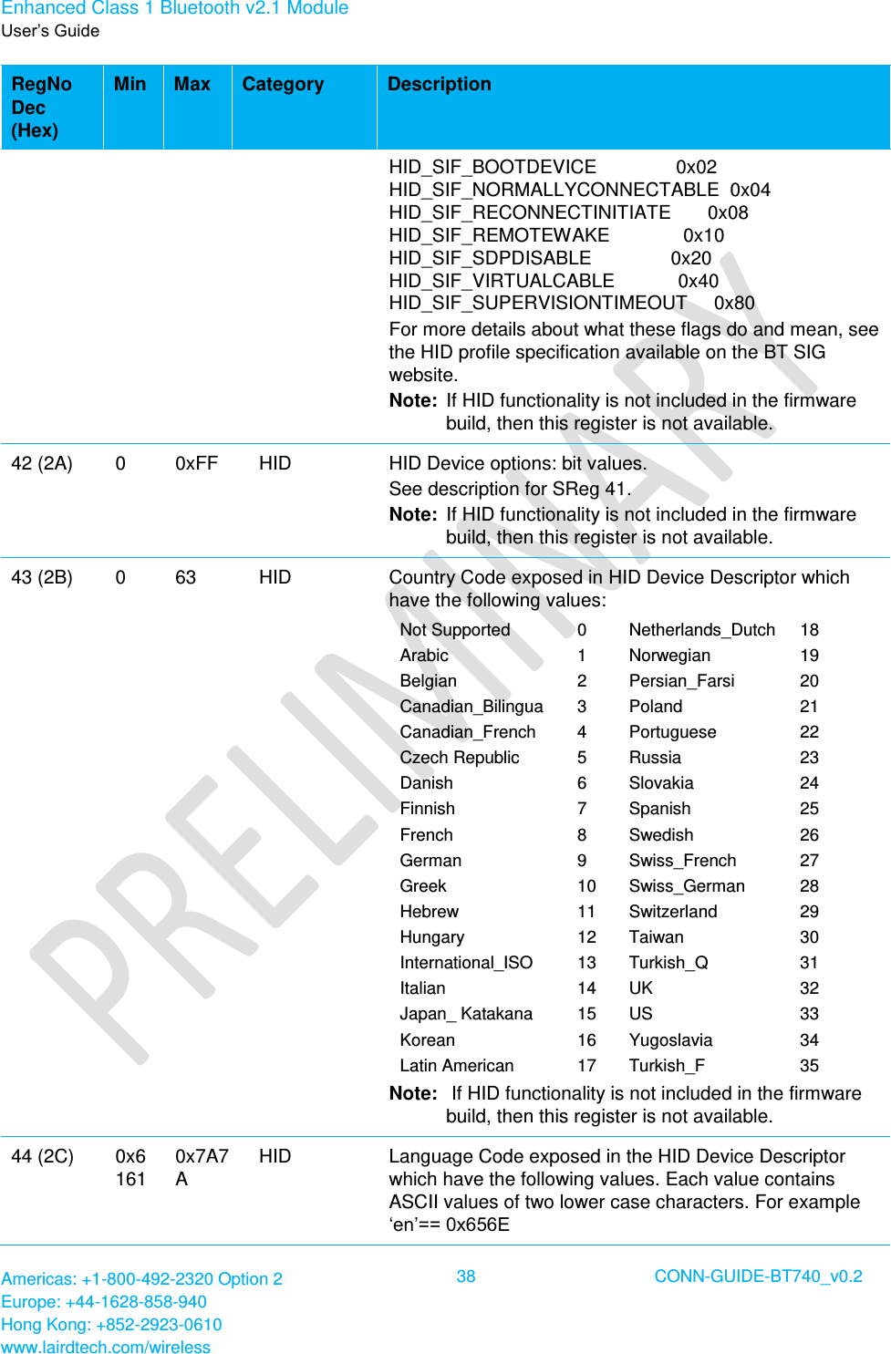
![Enhanced Class 1 Bluetooth v2.1 Module User’s Guide Americas: +1-800-492-2320 Option 2 Europe: +44-1628-858-940 Hong Kong: +852-2923-0610 www.lairdtech.com/wireless 60 CONN-GUIDE-BT740_v0.2 8.7.6 Host Packet Receive Flowchart As optimal data throughput is the design goal, the format and detail of packets have been constructed appropriately. It is recommended that the host implement the following flowchart, for rapid servicing and flow control of packets. On Packet ReceivePkt[2] & 0x80 ==0Pkt[1] ==0 Yes (Command) No (Data) Yes (Response) No (Event)Len >= 5Len >= 4ProcessDATALen > 2 Yes Yes Yes ProcessRESPONSEProcessEVENTEVT ==UNKNOWN_CMDEnd Yes Module willbe ready to recieve newcommandModule willbe ready to recieve newcommand Figure 8-1: Host packet receive flowchart](https://usermanual.wiki/Laird-Connectivity/BT700.user-manual-BT740-series/User-Guide-1969496-Page-60.png)
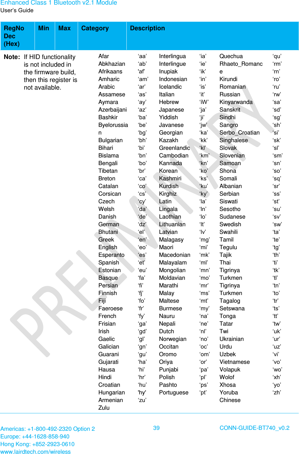
![Enhanced Class 1 Bluetooth v2.1 Module User’s Guide Americas: +1-800-492-2320 Option 2 Europe: +44-1628-858-940 Hong Kong: +852-2923-0610 www.lairdtech.com/wireless 61 CONN-GUIDE-BT740_v0.2 8.8 Host Command/Responses This section describes all host commands and confirms in detail what is specified via the CMD_ID/CNF_ID field of all command and confirm packets. The description for each command/confirm below is in the form of a command or confirm packet table and a corresponding response packet table when appropriate. Each command has a unique CMD_ID value in the range 1 to 63 (0x01 to 0x3F). 0 is reserved and confirms a CNF_ID in the range 64 to 127 (0x40 to 0x7F). The actual value of CMD_ID in the Value column is described as [Descriptive_Name] where “Descriptive_Name” can be found in a ‘C’ header file which can be obtained on request from Laird. The value of STATUS is similarly defined in a header file which can also be obtained from Laird. The commands are grouped as: Informational Configuration Connection Inquiry Pairing Miscellaneous They are described in subsequent sub chapters. 8.9 Information Commands This group of commands obtain information about the module. 8.9.1 No Operation This command results in no action other than to convey new FLOW_IN status to the module and get a response packet with the latest status for the FLOW_OUT bits. It is expected that a host uses this packet to poll for a change in the flow bits. Command Packet Offset Field Value Comments 0 LENGTH 4 Fixed 1 CHANNEL 0 Fixed 2 COMMAND [CMD_NO_OPERATION] 3 FLOW_IN ?? Runtime value Response Packet Offset Field Value Comments 0 LENGTH 5](https://usermanual.wiki/Laird-Connectivity/BT700.user-manual-BT740-series/User-Guide-1969496-Page-61.png)
![Enhanced Class 1 Bluetooth v2.1 Module User’s Guide Americas: +1-800-492-2320 Option 2 Europe: +44-1628-858-940 Hong Kong: +852-2923-0610 www.lairdtech.com/wireless 62 CONN-GUIDE-BT740_v0.2 Response Packet Offset Field Value Comments 1 CHANNEL 0 2 COMMAND [CMD_NO_OPERATION] 3 FLOW_OUT ?? Runtime value 4 STATUS [OK] Or [INVALID_LICENSE] 8.9.2 Get Connectable, Discoverable, Security Modes This command gets the current connectable, discoverable, and security modes. Command Packet Offset Field Value Comments 0 LENGTH 4 Fixed 1 CHANNEL 0 Fixed 2 COMMAND [CMD_GET_MODES] 3 FLOW_IN ?? Runtime value Response Packet Offset Field Value Comments 0 LENGTH 8 1 CHANNEL 0 2 COMMAND [CMD_GET_MODES] 3 FLOW_OUT ?? Runtime value 4 STATUS OK or INVALID_LICENSE 5 DISCMODE 0..3 Bit 0: 1 for discoverable mode Bit 1: 0 for generic, 1 for limited discovery mode. Bits 4..7: Future use specifying which limited inquiry access code to use. 6 CONNMODE 0..3 Bit 0: 1 for connectable mode Bit 1: 1 for Auto Accept Channel](https://usermanual.wiki/Laird-Connectivity/BT700.user-manual-BT740-series/User-Guide-1969496-Page-62.png)
![Enhanced Class 1 Bluetooth v2.1 Module User’s Guide Americas: +1-800-492-2320 Option 2 Europe: +44-1628-858-940 Hong Kong: +852-2923-0610 www.lairdtech.com/wireless 63 CONN-GUIDE-BT740_v0.2 Response Packet Offset Field Value Comments 7 SECMODE 12..15 12 = SSP + IO_CAP_NO_INPUT_NO_OUTPUT 13 = SSP + IO_CAP_DISPLAY_YES_NO 14 = SSP + IO_CAP_KEYBOARD_ONLY 15 = SSP + IO_CAP_DISPLAY_ONLY Note 1: SECMODE is now driven by the Simple Secure Pairing procedure included in and after v.2.1 of the BT specification. Note 2: For SECMODE, the No I/O Capability option is equivalent to the ‘Just Works’ scenario in SSP. Note 3: When this module interacts with a pre-2.1 device, it is unconditionally forced into legacy pairing mode. Note 4: Laird recommends that the reader become familiar with the SSP concept introduced in all subsequent version of BT (post v2.1). The best introduction is to Google the phrase Bluetooth Simple Secure Pairing. Note 5: Contact Laird for an informal discussion if necessary. 8.9.3 Read Local Bluetooth Address This command reads the Bluetooth address of the module. Command Packet Offset Field Value Comments 0 LENGTH 4 Fixed 1 CHANNEL 0 Fixed 2 COMMAND [CMD_READ_BLUETOOTH_ADDRESS] 3 FLOW_IN ?? Runtime value Response Packet Offset Field Value Comments 0 LENGTH 11 Fixed 1 CHANNEL 0 Fixed 2 COMMAND [CMD_READ_BLUETOOTH_ADDRESS] 3 FLOW_OUT ?? Runtime value 4 STATUS [OK]](https://usermanual.wiki/Laird-Connectivity/BT700.user-manual-BT740-series/User-Guide-1969496-Page-63.png)
![Enhanced Class 1 Bluetooth v2.1 Module User’s Guide Americas: +1-800-492-2320 Option 2 Europe: +44-1628-858-940 Hong Kong: +852-2923-0610 www.lairdtech.com/wireless 64 CONN-GUIDE-BT740_v0.2 5..10 BDADDR[] Nap[0,1]:Uap[2]:Lap[3,4,5] Bluetooth address](https://usermanual.wiki/Laird-Connectivity/BT700.user-manual-BT740-series/User-Guide-1969496-Page-64.png)
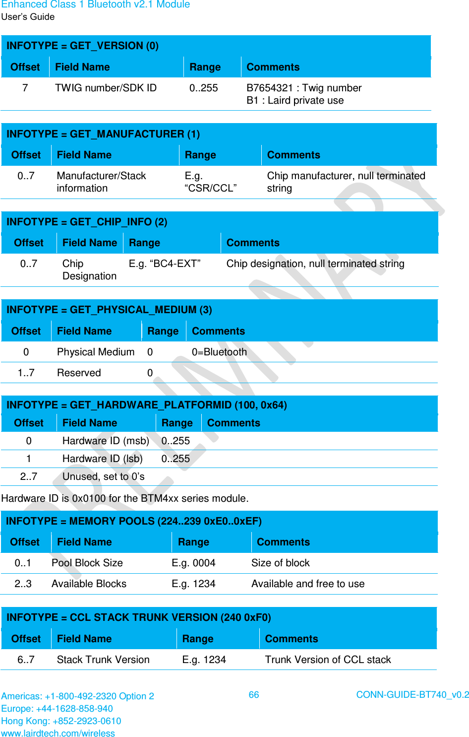
![Enhanced Class 1 Bluetooth v2.1 Module User’s Guide Americas: +1-800-492-2320 Option 2 Europe: +44-1628-858-940 Hong Kong: +852-2923-0610 www.lairdtech.com/wireless 65 CONN-GUIDE-BT740_v0.2 8.9.4 Information This command extracts information from the module, for example version number. Command Packet Offset Field Value Comments 0 LENGTH 5 Fixed 1 CHANNEL 0 Fixed 2 COMMAND [CMD_INFORMATION] 3 FLOW_IN ?? Runtime value 4 INFOTYPE 0..255 Response Packet Offset Field Value Comments 0 LENGTH 14 Fixed 1 CHANNEL 0 Fixed 2 COMMAND [CMD_INFORMATION] 3 FLOW_OUT ?? Runtime value 4 STATUS [OK] 5 INFOTYPE 0..255 Echoed from command 6.13 DATA[8] As per the table below The type of information requested is specified by the INFOTYPE parameter, as per the table below. INFOTYPE = GET_VERSION (0) Offset Field Name Range Comments 0 Format/Firmware/Platform ID 0..255 Bit 7: 1 Bit654: Spare Bit3210: Firmware/Platform ID 1 STACK_MAJOR 0..255 CCL Version number index 2 APP_MAJOR 0..255 Laird Application Version number index 3 DEVELOPER/BRANCH ID 0..255 Bit7654: Developer ID Bit3210: Branch ID 4..5 MSB/LSB of BUILD NUBMER 0..65535 Odd number == engineering Even Number == production 6 Reserved 0..255 Laird private use](https://usermanual.wiki/Laird-Connectivity/BT700.user-manual-BT740-series/User-Guide-1969496-Page-65.png)
![Enhanced Class 1 Bluetooth v2.1 Module User’s Guide Americas: +1-800-492-2320 Option 2 Europe: +44-1628-858-940 Hong Kong: +852-2923-0610 www.lairdtech.com/wireless 67 CONN-GUIDE-BT740_v0.2 INFOTYPE = CCL STACK BRANCH VERSION (241 0xF1) Offset Field Name Range Comments 6..7 Stack Branch Version E.g. 1234 Branch Version of CCL stack INFOTYPE = CCL STACK VENA VERSION (248 0xF8) Offset Field Name Range Comments 6..7 Stack VENA Version E.g. 1234 VENA Version of CCL stack 8.10 Configuration Commands This group of commands configures the module. 8.10.1 Read ‘S’ Register Configure the module using 32 bit integer values, which can be stored in non-volatile memory. Valid register numbers are in the range 0 to 255. See the S Registers section for a full list of all registers. The following command reads the current value of the S register REGNO. Command Packet Offset Field Value Comments 0 LENGTH 5 Fixed 1 CHANNEL 0 Fixed 2 COMMAND [CMD_READ_SREG] 3 FLOW_IN ?? Runtime value 4 REGNO 0 to 255 Response Packet Offset Field Value Comments 0 LENGTH 10 Fixed 1 CHANNEL 0 Fixed 2 COMMAND [CMD_READ_SREG] 3 FLOW_OUT ?? Runtime value 4 STATUS As appropriate 5 REGNO 0 to 255 Echoed from Command](https://usermanual.wiki/Laird-Connectivity/BT700.user-manual-BT740-series/User-Guide-1969496-Page-67.png)
![Enhanced Class 1 Bluetooth v2.1 Module User’s Guide Americas: +1-800-492-2320 Option 2 Europe: +44-1628-858-940 Hong Kong: +852-2923-0610 www.lairdtech.com/wireless 68 CONN-GUIDE-BT740_v0.2 Response Packet Offset Field Value Comments 6..9 REGVAL[] Register Value REGVAL[0] is the most significant octet. 8.10.2 Write ‘S’ Register This command writes a new value to the S register REGNO. See the S Registers section for a full list of all registers. Command Packet Offset Field Value Comments 0 LENGTH 9 Fixed 1 CHANNEL 0 Fixed 2 COMMAND [CMD_WRITE_SREG] 3 FLOW_IN ?? Runtime value 4 REGNO 0 to 255 5..8 REGVAL[] New Register Value REGVAL[0] is the most significant octet. Response Packet Offset Field Value Comments 0 LENGTH 10 1 CHANNEL 0 2 COMMAND [CMD_WRITE_SREG] 3 FLOW_OUT ?? Runtime value 4 STATUS As appropriate 5 REGNO 0 to 255 Echoed from Command 6..9 REGVAL[] Register Value REGVAL[0] is the most significant octet. 8.10.3 Store ‘S’ Registers This command saves the current ‘S’ register values in cache into the non-volatile memory so that they survive a power cycle. Command Packet Offset Field Value Comments 0 LENGTH 4 Fixed 1 CHANNEL 0 Fixed 2 COMMAND [CMD_STORE_SREG] 3 FLOW_IN ?? Runtime value](https://usermanual.wiki/Laird-Connectivity/BT700.user-manual-BT740-series/User-Guide-1969496-Page-68.png)
![Enhanced Class 1 Bluetooth v2.1 Module User’s Guide Americas: +1-800-492-2320 Option 2 Europe: +44-1628-858-940 Hong Kong: +852-2923-0610 www.lairdtech.com/wireless 69 CONN-GUIDE-BT740_v0.2 Response Packet Offset Field Value Comments 0 LENGTH 5 Fixed 1 CHANNEL 0 Fixed 2 COMMAND [CMD_STORE_SREG_] 3 FLOW_OUT ?? Runtime value 4 STATUS As appropriate 8.10.4 Default ‘S’ Registers This command forces all S register values in cache to factory defaults. Command Packet Offset Field Value Comments 0 LENGTH 4 Fixed 1 CHANNEL 0 Fixed 2 COMMAND [CMD_ DEFAULT_SREG] 3 FLOW_IN ?? Runtime value Response Packet Offset Field Value Comments 0 LENGTH 5 Fixed 1 CHANNEL 0 Fixed 2 COMMAND [CMD_ DEFAULT_SREG_] 3 FLOW_OUT ?? Runtime value 4 STATUS As appropriate 8.11 Connection Commands This group of commands manages connections. 8.11.1 Set Connectable Mode This command enables/disables connectable mode and specifies auto accept parameters for channels and muxs. Command Packet Offset Field Value Comments 0 LENGTH 6 Fixed 1 CHANNEL 0 Fixed 2 COMMAND [CMD_ CONNECTABLE_MODE]](https://usermanual.wiki/Laird-Connectivity/BT700.user-manual-BT740-series/User-Guide-1969496-Page-69.png)
![Enhanced Class 1 Bluetooth v2.1 Module User’s Guide Americas: +1-800-492-2320 Option 2 Europe: +44-1628-858-940 Hong Kong: +852-2923-0610 www.lairdtech.com/wireless 70 CONN-GUIDE-BT740_v0.2 Command Packet Offset Field Value Comments 3 FLOW_IN ?? Runtime value 4 ENABLE 0..1, 0xFF 0 = Disable, 1=Enable 0xFF = Read current mode 5 ACCEPT Bit mask Bit 0: Set to auto accept channel setup Bit 1..7: Reserved for future use If bit 0 is set then it overrides SReg 14 otherwise that S Register is consulted or incoming connections. Response Packet Offset Field Value Comments 0 LENGTH 6 Fixed 1 CHANNEL 0 Fixed 2 COMMAND [CMD_ CONNECTABLE_MODE] 3 FLOW_OUT ?? Runtime value 4 STATUS As appropriate 5 CURMODE 0..1 0 = Not connectable 1 = Connectable 8.11.2 Service Incoming Connection When the module is in connectable mode, incoming connection requests pass to the host via an EVT_CONNECTION_SETUP message – if and only if autoaccept is not enabled (via command or S register 14). The host accepts or rejects the remote connection request using this message. Command Packet Offset Field Value Comments 0 LENGTH 12 Fixed 1 CHANNEL 0 Fixed 2 COMMAND [CMD_ CONNECTION_SETUP] 3 FLOW_IN ?? Runtime value 4..9 BDADDR[] Nap[0,1]:Uap[2]:Lap[3,4,5] Bluetooth addr 10 HANDLE 0..255 Can be any value the host wants to set. This value is echoed by the module in the response. 11 ACCEPT 0..1 0 = reject. 1..255 = accept Response Packet Offset Field Value Comments 0 LENGTH 6 Fixed 1 CHANNEL 0 Fixed 2 COMMAND [CMD_ CONNECTION_SETUP] 3 FLOW_OUT ?? Runtime value 4 STATUS As appropriate 5 HANDLE 0..255 Echoed from the command](https://usermanual.wiki/Laird-Connectivity/BT700.user-manual-BT740-series/User-Guide-1969496-Page-70.png)
![Enhanced Class 1 Bluetooth v2.1 Module User’s Guide Americas: +1-800-492-2320 Option 2 Europe: +44-1628-858-940 Hong Kong: +852-2923-0610 www.lairdtech.com/wireless 71 CONN-GUIDE-BT740_v0.2 Receipt of the response is not an indication that the connection has established. If the connection is to be accepted, the module sends EVT_INCOMING_CONNECTION when the connection is fully established, as shown in the message sequence chart below. HOST MODULERSP_CONNECTION_SETUP (handle)CMD_CONNECTION_SETUP (bdaddr,accept,handle)EVT_CONNECTION_SETUP (bdaddr)Connection EstablishedIncoming connectionEVT_INCOMING_CONNECTION(channelid, bdaddr, uuid) Figure 8-2: Service Incoming Connection sequence diagram Note: If auto accept was specified when the module was put into connectable mode, then for incoming connections there is only an EVT_INCOMING_CONNECTION message. Connection EstablishedEVT_INCOMING_CONNECTION(channelid, bdaddr, uuid)Incoming connectionHOST MODULE Figure 8-3: Service Incoming Connection with auto accept specified 8.11.3 Make Outgoing Connection This command makes an outgoing connection to a profile in the remote peer. Command Packet Offset Field Value Comments 0 LENGTH 13 Fixed 1 CHANNEL 0 Fixed 2 COMMAND [CMD_ MAKE_CONNECTION] 3 FLOW_IN ?? Runtime value 4 HANDLE 0..255 Can be any value the host wants to set. This value is echoed by the module in the response. 5..10 BDADDR[] Nap[0,1]:Uap[2]:Lap[3,4,5] Bluetooth address 11..12 UUID[] 0x1101(SPP) 0x1124(HID) Uuid of the profile to connect to. Offset 11 is the MSB. 13 RFU 0 Always set to zero](https://usermanual.wiki/Laird-Connectivity/BT700.user-manual-BT740-series/User-Guide-1969496-Page-71.png)
![Enhanced Class 1 Bluetooth v2.1 Module User’s Guide Americas: +1-800-492-2320 Option 2 Europe: +44-1628-858-940 Hong Kong: +852-2923-0610 www.lairdtech.com/wireless 72 CONN-GUIDE-BT740_v0.2 Response Packet Offset Field Value Comments 0 LENGTH 7 Fixed 1 CHANNEL 0 Fixed 2 COMMAND [CMD_ MAKE_CONNECTION] 3 FLOW_OUT ?? Runtime value 4 STATUS As appropriate 5 HANDLE 0..255 Echoed from the command 6 CHANNEL 1..7 (SPP) 0x20,0x9x,0xA0 (HID DEVICE) Channel ID to be used for subsequent SPP data packets, and also when dropping the connection If the STATUS field in the response is MPSTATUS_OK, then a connection successfully established. Any other value is a failure. The content of ‘S’ register 11 specifies the max frame size to be used by the lower layers. Figure 8-4: Make Outgoing Connection sequence diagram When at least one connection is active (regardless of profile), the DCD output pin asserts. 8.11.4 Drop Connection This command destroys an existing channel. Command Packet Offset Field Value Comments 0 LENGTH 6 Fixed 1 CHANNEL 0 Fixed 2 COMMAND [CMD_ DROP_CONNECTION] 3 FLOW_IN ?? Runtime value 4 HANDLE 0..255 Can be any value the host wants to set. This value is echoed by the module in the response. 5 CHANNEL 1..7, As appropriate for other profiles As was specified in either RSP_MAKE_CONNECTION or](https://usermanual.wiki/Laird-Connectivity/BT700.user-manual-BT740-series/User-Guide-1969496-Page-72.png)
![Enhanced Class 1 Bluetooth v2.1 Module User’s Guide Americas: +1-800-492-2320 Option 2 Europe: +44-1628-858-940 Hong Kong: +852-2923-0610 www.lairdtech.com/wireless 73 CONN-GUIDE-BT740_v0.2 Command Packet Offset Field Value Comments EVT_INCOMMING_CONNECTION Response Packet Offset Field Value Comments 0 LENGTH Fixed 1 CHANNEL 0 Fixed 2 COMMAND [CMD_ DROP_CONNECTION] 3 FLOW_OUT ?? Runtime value 4 STATUS As appropriate 5 HANDLE 0..255 Echoed from the command If the STATUS field in the response is MPSTATUS_OK, then the request to drop the channel successfully submitted to the lower layers of the stack. When the channel drops, an EVT_DISCONNECT event sends to the host. When at least one connection is active (regardless of profile) the DCD output pin remains asserted. Figure 8-5: Drop Connection sequence diagram 8.12 Set Modem Lines Bluetooth Serial Port Profile is capable of exchanging modem signals DTR, DSR, RTS, CTS, DCD, and RI over air. From a host’s perspective, it can have DTR, RTS, DCD and RI as output lines. Note: DCD and RI are outputs for modems and ‘host’ in this context can mean either a PC or a peripheral like a modem. Additionally UARTs are capable of sending BREAK signals. BREAK output signals are non-idle state TX pins for a period much greater than the character width at the current baud rate setting.](https://usermanual.wiki/Laird-Connectivity/BT700.user-manual-BT740-series/User-Guide-1969496-Page-73.png)
![Enhanced Class 1 Bluetooth v2.1 Module User’s Guide Americas: +1-800-492-2320 Option 2 Europe: +44-1628-858-940 Hong Kong: +852-2923-0610 www.lairdtech.com/wireless 74 CONN-GUIDE-BT740_v0.2 This command sends DTR, RTS, DCD, and RI states to the peer device and also to specify a BREAK – Future Feature. Command Packet Offset Field Value Comments 0 LENGTH 7 Fixed 1 CHANNEL 0 Fixed 2 COMMAND [CMD_ CONTROLMODEMLINES] 3 FLOW_IN ?? Runtime value 4 CHANNEL 1..7 Channel ID of an open channel 5 MODEM Bit Mask Bit 0: DTR state Bit 1: RTS state Bit 2: DCD state Bit 3: RI state Bits 4 .. 7 : Ignored 6 BREAK 0 Not Available Response Packet Offset Field Value Comments 0 LENGTH 6 Fixed 1 CHANNEL 0 Fixed 2 COMMAND [CMD_ CONTROLMODEMLINES] 3 FLOW_OUT ?? Runtime value 4 STATUS As appropriate 5 CHANNEL 1..7 Echoed from command The STATUS value is MPSTATUS_OK if the message succeeded. Modem signals sent by the peer device present to the host in the message EVT_MODEM_STATUS defined in subsequent chapters. Note: BREAK signal capability is currently not provided by the lower stack, and so it is mentioned in the context of this command message for future implementation. 8.12.1 RSSI and Link Quality This command obtains the RSSI and Link Quality values for a given open connection. This is a parameter associated with the ACL connection to a peer device and does not have any meaning with channel IDs. Command Packet Offset Field Value Comments 0 LENGTH 10 Fixed 1 CHANNEL 0 Fixed](https://usermanual.wiki/Laird-Connectivity/BT700.user-manual-BT740-series/User-Guide-1969496-Page-74.png)
![Enhanced Class 1 Bluetooth v2.1 Module User’s Guide Americas: +1-800-492-2320 Option 2 Europe: +44-1628-858-940 Hong Kong: +852-2923-0610 www.lairdtech.com/wireless 75 CONN-GUIDE-BT740_v0.2 Command Packet Offset Field Value Comments 2 COMMAND [CMD_RSSI_LINKQUAL] 3 FLOW_IN ?? Runtime value 4..9 BDADDR[] Nap[0,1]:Uap[2]:Lap[3,4,5] Bluetooth addr Response Packet Offset Field Value Comments 0 LENGTH Fixed 1 CHANNEL 0 Fixed 2 COMMAND [CMD_RSSI_LINKQUAL] 3 FLOW_OUT ?? Runtime value 4 STATUS As appropriate 5..10 BDADDR[] Nap[0,1]:Uap[2]:Lap[3,4,5] Bluetooth addr 11 RSSI -128 to 127 RSSI value. Is zero if the signal is within the golden range 12 LINKQUAL 0 – 255 The definitions of RSSI and LINKQUAL are paraphrased from the Bluetooth specification as follows: 8.12.1.1 RSSI This value is the difference between the measured Received Signal Strength Indication (RSSI) and the limits of the Golden Receive Power Range (see Golden Receive Power Range). Any positive RSSI value returned by the Host Controller indicates how many dB the RSSI is above the upper limit; any negative value indicates how many dB the RSSI is below the lower limit. A value of zero indicates that the RSSI is inside the Golden Receive Power Range. Note: How accurate the dB values are depends on the Bluetooth hardware. The only requirements for the hardware are that the Bluetooth device is able to tell whether the RSSI is inside, above or below the Golden Device Power Range. 8.12.1.2 Golden Receive Power Range The lower threshold level of the golden receive power range corresponds to a received power between -56 dBm and 6 dB above the actual sensitivity of the receiver. The upper threshold level is 20 dB above the lower threshold level to an accuracy of +/- 6 dB. 8.12.1.3 Link Quality Link_Quality is a value from 0-255, which represents the quality of the link between two Bluetooth devices. The higher the value, the better the link quality. Each Bluetooth module vendor determines how to measure the link quality. In the case of CSR, this value is a measure of BER (Bit Error Rate).](https://usermanual.wiki/Laird-Connectivity/BT700.user-manual-BT740-series/User-Guide-1969496-Page-75.png)
![Enhanced Class 1 Bluetooth v2.1 Module User’s Guide Americas: +1-800-492-2320 Option 2 Europe: +44-1628-858-940 Hong Kong: +852-2923-0610 www.lairdtech.com/wireless 76 CONN-GUIDE-BT740_v0.2 8.13 Get Open Channel List This command obtains a list of channel IDs corresponding to connections which are open. It is a good method of querying the module to see how many Bluetooth connections are established and their corresponding channel ID numbers. A host should not need to use this command as it should be keeping track of the following two events and responses: EVT_DISCONNECT, EVT_CONNECTION_SETUP, RSP_MAKE_CONNECTION. Command Packet Offset Field Value Comments 0 LENGTH 10 Fixed 1 CHANNEL 0 Fixed 2 COMMAND [CMD_CHANNEL_LIST] 3 FLOW_IN ?? Runtime value Response Packet Offset Field Value Comments 0 LENGTH 22 Fixed 1 CHANNEL 0 Fixed 2 COMMAND [CMD_CHANNEL_LIST] 3 FLOW_OUT ?? Runtime value 4 STATUS As appropriate 5 Count 0..N Number of connections which have been established 6..21 Channel ID List[16] Array of 16 bytes A nonzero value implies a connection exists and the array element value identifies the channel ID 8.14 Inquiry Commands This group of commands performs inquiries and puts the module into discoverable mode. 8.14.1 Inquiry Request This command performs a Bluetooth inquiry. Command Packet Offset Field Value Comments 0 LENGTH 6 Fixed 1 CHANNEL 0 Fixed 2 COMMAND [CMD_INQUIRY_REQ]](https://usermanual.wiki/Laird-Connectivity/BT700.user-manual-BT740-series/User-Guide-1969496-Page-76.png)
![Enhanced Class 1 Bluetooth v2.1 Module User’s Guide Americas: +1-800-492-2320 Option 2 Europe: +44-1628-858-940 Hong Kong: +852-2923-0610 www.lairdtech.com/wireless 77 CONN-GUIDE-BT740_v0.2 Command Packet Offset Field Value Comments 3 FLOW_IN ?? Runtime value 4 MAXRESP 1..255 Maximum number of responses before aborting the inquiry procedure 5 TIMEOUT 1..120 Time in seconds, before aborting the inquiry procedure. 6 FLAGS 0..1 Bit 0 : 1 To allow repeat addresses. Bits 1..6 Reserved for future Bit 7 : Get Enhanced Inquiry responses Response Packet Offset Field Value Comments 0 LENGTH 7 Fixed 1 CHANNEL 0 Fixed 2 COMMAND [CMD_INQUIRY_REQ] 3 FLOW_OUT ?? Runtime value 4 STATUS As appropriate 5 TOTAL ?? The total number of inquiry responses that were received from peers. 6 DUMP ?? The total number of inquiry result events that were not sent because the transmit buffer of the module was full. This is a result of the host deasserting its RTS line. As a result of this command, as and when peer devices respond with inquiry responses, for each inquiry response, if bit 7 of the FLAGS field is zero then an event EVT_INQUIRY_RESULT sends to the host. If bit 7 of FLAGS field is one then, given that enhanced inquiry data has variable length data for any given response, the entire inquiry response sends via data channel 0xF0 to the host, with format described in subsections below. When the number of command-specified inquiry responses are received OR the specified time has elapsed, the final response is sent to indicate to the host that the inquiry procedure is complete. If the DUMP field in the response is non-zero, it is indicating that the host is not reading it’s receive buffer fast enough and is resulting in RTS deasserting towards the module. FLAGS bit 1-4 in future are to specify a limited access code inquiry. See message sequence diagram (Figure 8-6) which illustrates that the RSP_INQUIRY_REQ message terminates the inquiry process. 8.14.2 Enhanced Inquiry Data Packet Format When enhanced inquiry responses are requested via FLAGS bit 7 being set, each inquiry response sends to the host in data channel 0xF0 and the packet is formatted as follows: LL F0 AAAAAAAAAAAA CCCCCC RR EE…….EE](https://usermanual.wiki/Laird-Connectivity/BT700.user-manual-BT740-series/User-Guide-1969496-Page-77.png)
![Enhanced Class 1 Bluetooth v2.1 Module User’s Guide Americas: +1-800-492-2320 Option 2 Europe: +44-1628-858-940 Hong Kong: +852-2923-0610 www.lairdtech.com/wireless 78 CONN-GUIDE-BT740_v0.2 Where:: LL is the total length of the packet, and given only the EE..EE field is of variable length, the length of the EE..EE field is calculated by subtracting 12 (decimal) from LL. F0 is the channel number and is fixed AAAAAAAAAAAA is a 6 byte field containing the Bluetooth address of the responding device. CCCCCC is the device class code of the responding device RR is the measured RSSI value for that response (8 bit signed integer) EE..EE is a variable length field, with a maximum of 240 bytes, containing the enhanced inquiry data which is formatted as multiple len/tag/data structures as specified in the Bluetooth specification. Where both len and tag fields are single bytes and len does not include itself. Any data passed from the baseband must match the format defined in the Bluetooth Specification Version 2.1 + EDR [1], vol3, Part C – Generic Access Profile, 8 Extended Inquiry Response Data Format (page 1305 in the *.pdf file). A typical message sequence is as follows: Figure 8-6: Typical message sequence 8.14.3 Set Discoverable Mode This command enables/disables discoverable mode. Command Packet Offset Field Value Comments 0 LENGTH 5 Fixed 1 CHANNEL 0 Fixed 2 COMMAND [CMD_ DISCOVERABLE_MODE]](https://usermanual.wiki/Laird-Connectivity/BT700.user-manual-BT740-series/User-Guide-1969496-Page-78.png)
![Enhanced Class 1 Bluetooth v2.1 Module User’s Guide Americas: +1-800-492-2320 Option 2 Europe: +44-1628-858-940 Hong Kong: +852-2923-0610 www.lairdtech.com/wireless 79 CONN-GUIDE-BT740_v0.2 3 FLOW_IN ?? Runtime value 4 MODE 0..1, 0xFF 0 = Disable, 1 = Generic Access Code 0xFF = Read current mode Response Packet Offset Field Value Comments 0 LENGTH 6 Fixed 1 CHANNEL 0 Fixed 2 COMMAND [CMD_ DISCOVERABLE_MODE] 3 FLOW_OUT ?? Runtime value 4 STATUS As appropriate 5 CURMODE 0..1 1 = Generic Access Code The module uses the parameters stored in ‘S’ Registers 7 and 8 to set the inquiry scan interval and window. Inquiry scan is how often (interval) the radio listens for an inquirer and for how long (window) each time. 8.15 Pairing Commands This group of commands manages either incoming or outgoing pairings and the trusted device database which resides in the non-volatile memory of the module. The trusted device database is a database with a two tables, each with records of two fields. One field is the Bluetooth address of a paired device and the other stores the 16 byte link key. One database is classed a ROLLING database and stores new pairing information as they happen. If the database is full, then the oldest is discarded to make space for the latest one. The other database is classed as a PERSISTANT database which stores pairing information which can ONLY be deleted when a new pairing initiates to that particular device OR on request from the host. The host protocol provides for a command to transfer a record between these two databases. In addition there is a command for the host to determine if a device is trusted. There is also a command to manually insert a device and its link key into the database. Depending on the peer device, either a legacy pairing procedure or a simple secure pairing occurs. A legacy pairing occurs if the peer device is older than v2.1 of the Bluetooth specification. Simple Secure Pairing (for v2.1 and newer devices) uses a Diffie-Hellman procedure to exchange the secret link key, but is vulnerable to man-in-the-middle attack. When pairing initiates and a legacy 2.0 or older device is not involved, then the basebands perform an I/O capability negotiation with each other to see whether it shall perform a ‘Just Works’ unathenticated pairing with no man-in-the-middle (MITM) protection or an authenticated pairing which requires user interaction. The I/O capability is one of: Display Only Keyboard Only Display with Yes/No button](https://usermanual.wiki/Laird-Connectivity/BT700.user-manual-BT740-series/User-Guide-1969496-Page-79.png)
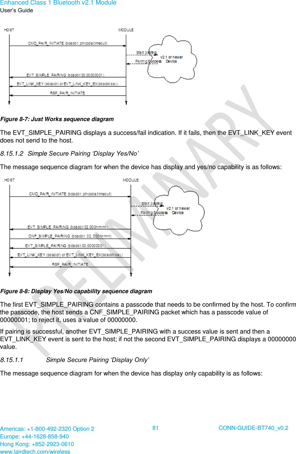
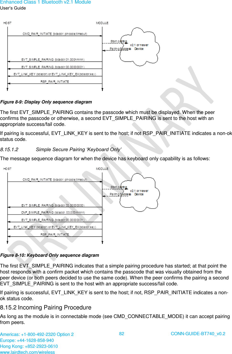
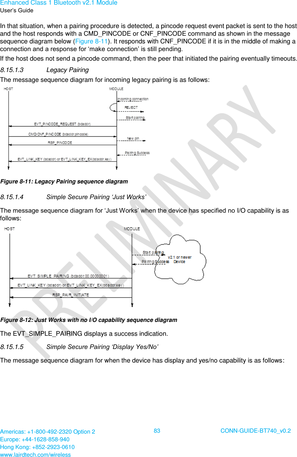
![Enhanced Class 1 Bluetooth v2.1 Module User’s Guide Americas: +1-800-492-2320 Option 2 Europe: +44-1628-858-940 Hong Kong: +852-2923-0610 www.lairdtech.com/wireless 80 CONN-GUIDE-BT740_v0.2 For example: If one end has Display only, but the other end has keyboard only, then the negotiation results in one end displaying a six digit passcode on the Display Only side, which is then required to be entered at the keyboard only end. If both ends have Display with Yes/No, then during the procedure both ends display a six digit passcode which needs to be visually compared and then the Yes/No buttons are used to confirm that they match. This provides for a one in a million probability that a MITM attach is successful. To enable this new interaction with a user during pairing a new EVT_SIMPLE_PAIRING was defined. 8.15.1 Pair Initiate This command initiates a pairing with a peer device which is assumed to be ready and waiting for a pairing. If that device is compliant with v2.0 and older of the Bluetooth specification then a legacy pairing results and the pincode pin[] in this message is used otherwise there is a simple pairing procedure. Command Packet Offset Field Value Comments 0 LENGTH 28 Fixed 1 CHANNEL 0 Fixed 2 COMMAND [CMD_ PAIR_INITIATE] 3 FLOW_IN ?? Runtime value 4 TIMEOUT 5..120 Pairing timeout in seconds 5..10 BDADDR[] Nap[0,1]:Uap[2]:Lap[3,4,5] Bluetooth addr of device to be paired 11..27 PIN[] 17 byte string array Null Terminated Pin code String. Maximum pin code length is 16. Response Packet Offset Field Value Comments 0 LENGTH 5 Fixed 1 CHANNEL 0 Fixed 2 COMMAND [CMD_ PAIR_INITIATE] 3 FLOW_OUT ?? Runtime value 4 STATUS As appropriate If pairing is successful, the event message EVT_LINK_KEY or EVT_LINK_KEY_EX sends to the host before the response to close the procedure, as shown in the message sequence chart below. Pair Initiate may fail if there are any existing open connections. The status byte in the response will have an appropriate value. 8.15.1.1 Simple Secure Pairing ‘Just Works’ The message sequence diagram for ‘Just Works’ when the device has specified no I/O capability is as follows:](https://usermanual.wiki/Laird-Connectivity/BT700.user-manual-BT740-series/User-Guide-1969496-Page-80.png)
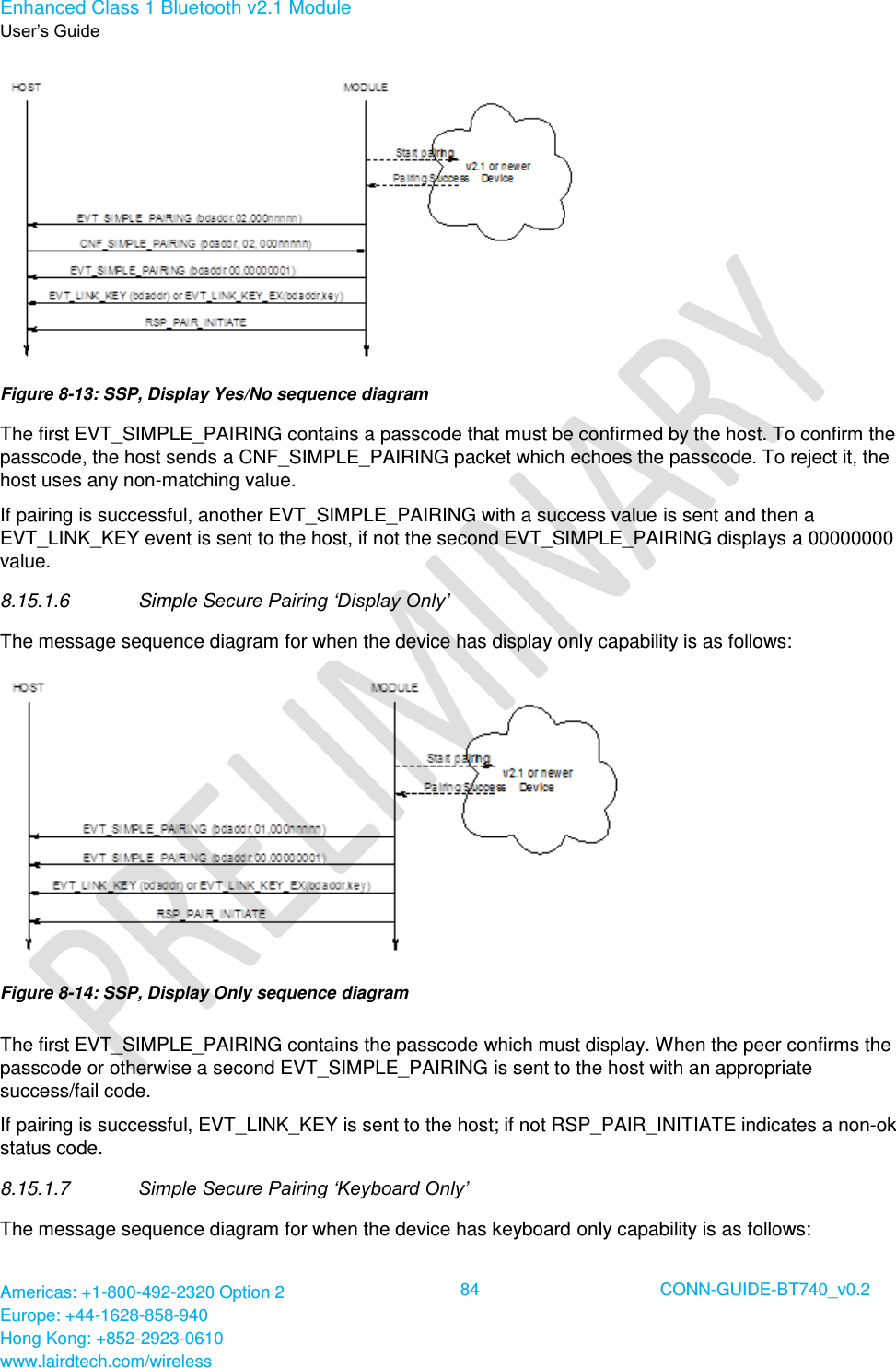
![Enhanced Class 1 Bluetooth v2.1 Module User’s Guide Americas: +1-800-492-2320 Option 2 Europe: +44-1628-858-940 Hong Kong: +852-2923-0610 www.lairdtech.com/wireless 85 CONN-GUIDE-BT740_v0.2 Figure 8-15: SSP, Keyboard Only sequence diagram The first EVT_SIMPLE_PAIRING indicates that a simple pairing procedure started and at that point the host responds with a confirm packet which contains the passcode that was visually obtained from the peer device (or both peers decided to use the same code). When the peer confirms the pairing, a second EVT_SIMPLE_PAIRING is sent to the host with an appropriate success/fail code. If pairing is successful, EVT_LINK_KEY is sent to the host; if not RSP_PAIR_INITIATE indicates a non-ok status code 8.15.3 SIMPLE PAIRING Confirmation This confirmation packet provides a response to the module as a result of a EVT_SIMPLE_PAIRING event and conveys to the module additional information required to complete a simple pairing procedure. This is a confirmation packet and does not result in a response from the module. Event Packet Offset Field Value Comments 0 LENGTH 15 1 CHANNEL 0 2 EVENT [CNF_ SIMPLE_PAIRING] 3 FLOW_OUT ?? Runtime value 4..9 BDADDR[6] Nap[0,1]:Uap[2]:Lap[3,4,5] Bluetooth address of pairing device 10 action 2..3 See description below 11..14 actionval 4 bytes See description below Action :: 0 & 1 This is illegal and is ignored by the module. Action :: 2 This informs the module the response to a YES/NO query. Set ‘actionval’ to 00000000 for NO and non-00000000 for YES. Action :: 3](https://usermanual.wiki/Laird-Connectivity/BT700.user-manual-BT740-series/User-Guide-1969496-Page-85.png)
![Enhanced Class 1 Bluetooth v2.1 Module User’s Guide Americas: +1-800-492-2320 Option 2 Europe: +44-1628-858-940 Hong Kong: +852-2923-0610 www.lairdtech.com/wireless 86 CONN-GUIDE-BT740_v0.2 This informs the module the response to a passcode query. In this case the ‘actionval’ conveys the passcode value. Note: A successful connection to an unpaired 2.1 and newer device requires this confirmation packet because the MP protocol does not process new commands unless the previous command was completed by sending an appropriate response packet. The packet processor in the module queues all commands until a response sends, but processes confirmation packets as they come. 8.15.4 PinCode (Command) This command sends a pincode in response to an EVT_PINCODE_REQUEST message and results in a RSP_PINCODE from the module to the host. This command can also register a pincode for all subsequent incoming legacy pairings from BT2.0 and older devices. In that case the BDADDR[] field MUST be set to all zeros. Command Packet Offset Field Value Comments 0 LENGTH 28 Fixed 1 CHANNEL 0 Fixed 2 COMMAND [CMD_PINCODE] 3 FLOW_IN ?? Runtime value 4 TIMEOUT 5..120 Pairing timeout in seconds 5..10 BDADDR[] Nap[0,1]:Uap[2]:Lap[3,4,5] Bluetooth address of device requesting the pairing. Or all zeros to register a pincode for incoming pairings 11..27 PIN[] 17 byte string array Null Terminated Pin code String. Maximum pin code length is 16. Response Packet Offset Field Value Comments 0 LENGTH 5 Fixed 1 CHANNEL 0 Fixed 2 COMMAND [CMD_PINCODE] 3 FLOW_OUT ?? Runtime value 4 STATUS As appropriate If pairing is successful the event message EVT_LINK_KEY or EVT_LINK_KEY_EX sends to the host after the response. The latter event sends if S Register 47 is set to 1.](https://usermanual.wiki/Laird-Connectivity/BT700.user-manual-BT740-series/User-Guide-1969496-Page-86.png)
![Enhanced Class 1 Bluetooth v2.1 Module User’s Guide Americas: +1-800-492-2320 Option 2 Europe: +44-1628-858-940 Hong Kong: +852-2923-0610 www.lairdtech.com/wireless 87 CONN-GUIDE-BT740_v0.2 8.15.5 PinCode (Confirmation) This is a confirmation packet which sends a pincode in response to an EVT_PINCODE_REQUEST message while making an outgoing connection to a legacy pairing device and there was a pairing challenge by the peer prior to connection acceptance. This packet, just like the command version of this packet, can also register a pincode for all subsequent incoming legacy pairings from BT2.0 and older devices. In that case the BDADDR[] field MUST be set to all zeros. Command Packet Offset Field Value Comments 0 LENGTH 28 Fixed 1 CHANNEL 0 Fixed 2 COMMAND [CNF_PINCODE] 3 FLOW_IN ?? Runtime value 4 TIMEOUT 5..120 Pairing timeout in seconds 5..10 BDADDR[] Nap[0,1]:Uap[2]:Lap[3,4,5] Bluetooth address of device requesting the pairing. Or all zeros to register a pincode for incoming pairings 11..27 PIN[] 17 byte string array Null Terminated Pin code String. Maximum pin code length is 16. If pairing is successful, the event message EVT_LINK_KEY or EVT_LINK_KEY_EX is sent to the host after the response. The latter event sends if S Register 47 is set to one. Note: A successful connection to an unpaired 2.0 and newer device requires this confirmation packet because the MP protocol does not process new commands unless the previous command was completed by sending an appropriate response packet. The packet processor in the module queues all commands until a response sends, but processes confirmation packets as they come hence in this case CMD_PINCODE does not work. 8.15.6 Trusted Database Record Count This command obtains the number of trusted devices in the database specified. Command Packet Offset Field Value Comments 0 LENGTH 5 Fixed 1 CHANNEL 0 Fixed 2 COMMAND [CMD_ TRUSTED_DB_COUNT] 3 FLOW_IN ?? Runtime value 4 DBTYPE 0..1 0 = ROLLING DATABASE 1 = PERSISTANT DATABASE](https://usermanual.wiki/Laird-Connectivity/BT700.user-manual-BT740-series/User-Guide-1969496-Page-87.png)
![Enhanced Class 1 Bluetooth v2.1 Module User’s Guide Americas: +1-800-492-2320 Option 2 Europe: +44-1628-858-940 Hong Kong: +852-2923-0610 www.lairdtech.com/wireless 88 CONN-GUIDE-BT740_v0.2 Response Packet Offset Field Value Comments 0 LENGTH 8 Fixed 1 CHANNEL 0 Fixed 2 COMMAND [CMD_ TRUSTED_DB_COUNT] 3 FLOW_OUT ?? Runtime value 4 STATUS As appropriate 5 DBTYPE 0..1 Echoed from command 6 COUNT 0..N Number of trusted devices in this database 7 MAXCOUNT 0..N Maximum number of devices that can be stored in this database Note: ROLLING database stores all new pairings automatically. It is up to the host to transfer a record from ROLLING to the PERSISTANT database so that it does not get overwritten.](https://usermanual.wiki/Laird-Connectivity/BT700.user-manual-BT740-series/User-Guide-1969496-Page-88.png)
![Enhanced Class 1 Bluetooth v2.1 Module User’s Guide Americas: +1-800-492-2320 Option 2 Europe: +44-1628-858-940 Hong Kong: +852-2923-0610 www.lairdtech.com/wireless 89 CONN-GUIDE-BT740_v0.2 8.15.7 Trusted Database Read Record This command reads the Bluetooth address of the ITEMNO pairing in the database specified, counted from the top. ITEMNO is indexed from one. Command Packet Offset Field Value Comments 0 LENGTH 6 Fixed 1 CHANNEL 0 Fixed 2 COMMAND [CMD_TRUSTED_DB_READ] 3 FLOW_IN ?? Runtime value 4 DBTYPE 0..1 0 = ROLLING DATABASE 1 = PERSISTANT DATABASE 5 ITEMNO 1..N Item number to read Response Packet Offset Field Value Comments 0 LENGTH 13 Fixed 1 CHANNEL 0 Fixed 2 COMMAND [CMD_TRUSTED_DB_READ] 3 FLOW_OUT ?? Runtime value 4 STATUS As appropriate 5 DBTYPE 0..1 Echoed from command 6 ITEMNO 1..N Echoed from command 7..12 BDADDR[] Nap[0,1]:Uap[2]:Lap[3,4,5] Bluetooth addr is all zeros if the item specified does not exist If S Reg 47 is set to one, then it is possible to read a record so that both the address and link key information is supplied by sending the command CMD_ TRUSTED_DB_ISTRUSTED. In that case, the event EVT_LINK_KEY_EX is sent before the response to CMD_TRUSTED_DB_ISTRUSTED. 8.15.8 Trusted Database Delete Record This command deletes a pairing from the databases. It is not necessary to specify the database type, as both databases are scanned. Command Packet Offset Field Value Comments 0 LENGTH 10 Fixed 1 CHANNEL 0 Fixed 2 COMMAND [CMD_ TRUSTED_DB_DELETE]](https://usermanual.wiki/Laird-Connectivity/BT700.user-manual-BT740-series/User-Guide-1969496-Page-89.png)
![Enhanced Class 1 Bluetooth v2.1 Module User’s Guide Americas: +1-800-492-2320 Option 2 Europe: +44-1628-858-940 Hong Kong: +852-2923-0610 www.lairdtech.com/wireless 90 CONN-GUIDE-BT740_v0.2 Command Packet Offset Field Value Comments 3 FLOW_IN ?? Runtime value 4..9 BDADDR[] Nap[0,1]:Uap[2]:Lap[3,4,5] Bluetooth addr of device to be unpaired Response Packet Offset Field Value Comments 0 LENGTH 11 Fixed 1 CHANNEL 0 Fixed 2 COMMAND [CMD_ TRUSTED_DB_DELETE] 3 FLOW_OUT ?? Runtime value 4 STATUS As appropriate 5..10 BDADDR[] Nap[0,1]:Uap[2]:Lap[3,4,5] Bluetooth addr, echoed from the command 8.15.9 Trusted Database Change Type This command transfers a record to the database specified. Command Packet Offset Field Value Comments 0 LENGTH 11 Fixed 1 CHANNEL 0 Fixed 2 COMMAND [CMD_TRUSTED_DB_CHANGETYPE] 3 FLOW_IN ?? Runtime value 4 DBTYPE 0..1 5..10 BDADDR[] Nap[0,1]:Uap[2]:Lap[3,4,5] Bluetooth addr Response Packet Offset Field Value Comments 0 LENGTH 12 Fixed 1 CHANNEL 0 Fixed 2 COMMAND [CMD_TRUSTED_DB_CHANGETYPE] 3 FLOW_OUT ?? Runtime value 4 STATUS As appropriate 5 DBTYPE 0..1 Echoed from command 6..11 BDADDR[] Nap[0,1]:Uap[2]:Lap[3,4,5] Bluetooth addr, echoed from the command](https://usermanual.wiki/Laird-Connectivity/BT700.user-manual-BT740-series/User-Guide-1969496-Page-90.png)
![Enhanced Class 1 Bluetooth v2.1 Module User’s Guide Americas: +1-800-492-2320 Option 2 Europe: +44-1628-858-940 Hong Kong: +852-2923-0610 www.lairdtech.com/wireless 91 CONN-GUIDE-BT740_v0.2 8.15.10 Trusted Database Is Peer Trusted This command checks if a device is trusted. Command Packet Offset Field Value Comments 0 LENGTH 10 Fixed 1 CHANNEL 0 Fixed 2 COMMAND [CMD_ TRUSTED_DB_ISTRUSTED] 3 FLOW_IN ?? Runtime value 4..9 BDADDR[] Nap[0,1]:Uap[2]:Lap[3,4,5] Bluetooth addr Response Packet Offset Field Value Comments 0 LENGTH 11 Fixed 1 CHANNEL 0 Fixed 2 COMMAND [CMD_ TRUSTED_DB_ISTRUSTED] 3 FLOW_OUT ?? Runtime value 4 STATUS As appropriate 5..10 BDADDR[] Nap[0,1]:Uap[2]:Lap[3,4,5] Bluetooth addr, echoed from the command The STATUS value is MPSTATUS_OK if the device is trusted; any other value means not trusted. If S Reg 47 is set to one, then if the peer device is found in the trusted device database, then the event EVT_LINK_KEY_EX is sent to the host BEFORE the response. That event contains the address and link key associated with that address. 8.15.11 Trusted Database Add Key (Out-Of-Band Facilitator) This command manually adds a link key/address pair into the rolling trusted database. The module does not care how the key was generated and the only validation it performs is to check that it is 16 bytes long. Command Packet Offset Field Value Comments 0 LENGTH 1E Fixed 1 CHANNEL 0 Fixed 2 COMMAND [CMD_ TRUSTED_DB_ADD] 3 FLOW_IN ?? Runtime value 4..9 BDADDR[6] Nap[0,1]:Uap[2]:Lap[3,4,5] Bluetooth addr](https://usermanual.wiki/Laird-Connectivity/BT700.user-manual-BT740-series/User-Guide-1969496-Page-91.png)
![Enhanced Class 1 Bluetooth v2.1 Module User’s Guide Americas: +1-800-492-2320 Option 2 Europe: +44-1628-858-940 Hong Kong: +852-2923-0610 www.lairdtech.com/wireless 92 CONN-GUIDE-BT740_v0.2 Command Packet Offset Field Value Comments 10..25 KEY[16] 16 byte Link Key Any random value 26..29 FLAGS[4] 00 00 00 00 For future use and MUST be set to 00000000 Response Packet Offset Field Value Comments 0 LENGTH 11 Fixed 1 CHANNEL 0 Fixed 2 COMMAND [CMD_ TRUSTED_DB_ADD] 3 FLOW_OUT ?? Runtime value 4 STATUS As appropriate The STATUS value is MPSTATUS_OK if the device was successfully added to the database. If the device Bluetooth address is already in the trusted device database, then the old one is deleted and is replaced by this new one. 8.16 Miscellaneous Commands 8.16.1 Get Security Mode This command gets the current security mode of the module. Bluetooth v2.1 and newer devices cannot disable security therefore only values 12 to 15 inclusive are valid. These values specify Simple Secure Pairing with appropriate I/O capabilities. Specifying a value of 0xFF means leave the mode as it is, but inform the host with regards to current mode. Command Packet Offset Field Value Comments 0 LENGTH 5 Fixed 1 CHANNEL 0 Fixed 2 COMMAND [CMD_SECURITY_MODE] 3 FLOW_IN ?? Runtime value 4 SECMODE 0xFF 0xFF = Get current mode Response Packet Offset Field Value Comments 0 LENGTH 6 Fixed 1 CHANNEL 0 Fixed](https://usermanual.wiki/Laird-Connectivity/BT700.user-manual-BT740-series/User-Guide-1969496-Page-92.png)
![Enhanced Class 1 Bluetooth v2.1 Module User’s Guide Americas: +1-800-492-2320 Option 2 Europe: +44-1628-858-940 Hong Kong: +852-2923-0610 www.lairdtech.com/wireless 93 CONN-GUIDE-BT740_v0.2 Response Packet Offset Field Value Comments 2 COMMAND [CMD_SECURITY_MODE] 3 FLOW_OUT ?? Runtime value 4 STATUS As appropriate 5 SECMODE 12..15 Current mode 12 = SSP with no input no output 13 = SSP with yes/no display 14 = SSP with keyboard only 15 = SSP with Display only 1. SECMODE is now driven by the ‘Simple Secure Pairing’ procedure which got included in and after v2.1 of the Bluetooth specification 2. For ‘SECMODE’ the ‘No I/O capability’ option is equivalent to ‘Just works’ scenario in Simple Secure pairing. 3. When this module interacts with a pre 2.1 device it is unconditionally forced into legacy pairing mode. 4. The reader should become familiar with the ‘Simple Secure Pairing’ concept introduced in and all subsequent version of Bluetooth after v2.1. The best introduction is to Google the phrase “Bluetooth Simple Secure Pairing”. 5. The reader is also welcome to contact Laird for an informal discussion. 8.16.2 Get Remote Friendly Name This command gets the friendly name of the specified peer device. According to the Bluetooth specification, a friendly name can be up to 248 bytes long. Sending this name in its entirety to the host could violate the max packet length capability of the host because memory restrictions in the host or transmit buffers in the module may not be able to cope. Therefore, the mechanism for getting the name to the host is via multiple event packets is EVT_REM_FNAME. The host decides how many bytes of the name are passed up to it via these events from the offset it also specifies. This implies that in a memory constraint environment, it is possible to relay the name to the host using multiple commands. For example, if the host has space for only 10 bytes and a peer happens to have a very long name, the host can ask for 10 byte fragments of the name over multiple get name requests. Command Packet Offset Field Value Comments 0 LENGTH 13 Fixed 1 CHANNEL 0 Fixed 2 COMMAND [CMD_GET_REM_FNAME] 3 FLOW_IN ?? Runtime value 4..9 BDADDR[] Nap[0,1]:Uap[2]:Lap[3,4,5] Bluetooth addr 10 TIMEOUT 2..120 Timeout in seconds 11 START N Offset into the friendly name string 12 MAXBYTES M Maximum number of](https://usermanual.wiki/Laird-Connectivity/BT700.user-manual-BT740-series/User-Guide-1969496-Page-93.png)
![Enhanced Class 1 Bluetooth v2.1 Module User’s Guide Americas: +1-800-492-2320 Option 2 Europe: +44-1628-858-940 Hong Kong: +852-2923-0610 www.lairdtech.com/wireless 94 CONN-GUIDE-BT740_v0.2 characters to read Response Packet Offset Field Value Comments 0 LENGTH 8 Fixed 1 CHANNEL 0 Fixed 2 COMMAND [CMD_GET_REM_FNAME] 3 FLOW_OUT ?? Runtime value 4 STATUS As appropriate 5 NAMELEN 0..248 Actual size of the friendly name 6 START N Echoed from the command 7 SENTLEN S Total number of bytes sent Note: SENTLEN could be less than MAXBYTES. It can happen if there is no space in the module’s TX buffer to send events. HOST MODULEReq Friendly NameEVT_REM_FNAME (index=0,len=10,"?????")CMD_REM_FNAME (bdaddr, timeout, start=0, maxbytes=25)EVT_REM_FNAME (index=10,len=10,"?????")EVT_REM_FNAME (index=20,len=5,"?????")Got Friendly Name (47 bytes)CMD_REM_FNAME (namelen=47,start=0,sent=25)CMD_REM_FNAME (bdaddr, timeout, start=25, maxbytes=22)Req Friendly NameGot Friendly Name (47 bytes)EVT_REM_FNAME (index=25,len=10,"?????")EVT_REM_FNAME (index=35,len=10,"?????")EVT_REM_FNAME (index=45,len=2,"?????")CMD_REM_FNAME (namelen=47,start=25,sent=22) Figure 8-16: Get Remote Friendly Name sequence diagram 8.16.3 Get Local Friendly Name This command reads the local friendly name which stores in non-volatile memory. Unlike the remote friendly name where there is no control over the maximum length, the local friendly name is limited to 31 characters.](https://usermanual.wiki/Laird-Connectivity/BT700.user-manual-BT740-series/User-Guide-1969496-Page-94.png)
![Enhanced Class 1 Bluetooth v2.1 Module User’s Guide Americas: +1-800-492-2320 Option 2 Europe: +44-1628-858-940 Hong Kong: +852-2923-0610 www.lairdtech.com/wireless 95 CONN-GUIDE-BT740_v0.2 This length may still be too big to send to the host in one packet. Therefore the name sends in a similar fashion to ‘get friendly name’ described above. However, in this case, the event EVT_LCL_FNAME gets the name to the host. Command Packet Offset Field Value Comments 0 LENGTH 6 Fixed 1 CHANNEL 0 Fixed 2 COMMAND [CMD_GET_LCL_FNAME] 3 FLOW_IN ?? Runtime value 4 START n Offset into the friendly name string 5 MAXBYTES m Maximum number of characters to read Response Packet Offset Field Value Comments 0 LENGTH Fixed 1 CHANNEL 0 Fixed 2 COMMAND [CMD_GET_LCL_FNAME] 3 FLOW_OUT ?? Runtime value 4 STATUS As appropriate 5 NAMELEN 0..31 Actual size of the friendly name 6 START n Echoed from the command 7 SENTLEN S Total number of bytes sent in preceding events. The name string sends to the host in EVT_LCL_FNAME packets. See description of Get Remote Friendly name Note: SENTLEN could be less than MAXBYTES. It can happen if there is no space in the module’s TX buffer to send events. 8.16.4 Set Local Friendly Name This command sets the local friendly name in non-volatile memory so that it is used after a power up/reset cycle. Since the module can cope with large packets, the name sent to the module in a single command packet as a null terminated string. Command Packet Offset Field Value Comments](https://usermanual.wiki/Laird-Connectivity/BT700.user-manual-BT740-series/User-Guide-1969496-Page-95.png)
![Enhanced Class 1 Bluetooth v2.1 Module User’s Guide Americas: +1-800-492-2320 Option 2 Europe: +44-1628-858-940 Hong Kong: +852-2923-0610 www.lairdtech.com/wireless 96 CONN-GUIDE-BT740_v0.2 Command Packet Offset Field Value Comments 0 LENGTH 37 Fixed 1 CHANNEL 0 Fixed 2 COMMAND [CMD_SET_LCL_FNAME] 3 FLOW_IN ?? Runtime value 4 FLAGS 1..2 1 = Write to non-vol store for use on next power up 2 = Make the name visible now 5 NAMELEN 1..30 6..36 NAME[31] Null terminated string Not more than 30 characters Response Packet Offset Field Value Comments 0 LENGTH 5 Fixed 1 CHANNEL 0 Fixed 2 COMMAND [CMD_SET_LCL_FNAME] 3 FLOW_OUT ?? Runtime value 4 STATUS As appropriate 8.16.5 Set Device Class This command sets the device class code so that the base band makes it visible immediately. This is opposed to setting it via S Register 120 which only expedites on power up. Command Packet Offset Field Value Comments 0 LENGTH 7 Fixed 1 CHANNEL 0 Fixed 2 COMMAND [CMD_SET_DEVCLASS] 3 FLOW_IN ?? Runtime value 4..6 DEVCLASS[3] New 24 bit device class MSB of device class is at offset 4 Response Packet Offset Field Value Comments 0 LENGTH Fixed 1 CHANNEL 0 Fixed 2 COMMAND [CMD_SET_DEVCLASS] 3 FLOW_OUT ?? Runtime value](https://usermanual.wiki/Laird-Connectivity/BT700.user-manual-BT740-series/User-Guide-1969496-Page-96.png)
![Enhanced Class 1 Bluetooth v2.1 Module User’s Guide Americas: +1-800-492-2320 Option 2 Europe: +44-1628-858-940 Hong Kong: +852-2923-0610 www.lairdtech.com/wireless 98 CONN-GUIDE-BT740_v0.2 8.16.6 Factory Default This command clears non-volatile memory in the module so that it reverts to factory default state. The FLAGS field is a bit mask which selectively clears various types of non-volatile memory and should be set to FF. Command Packet Offset Field Value Comments 0 LENGTH 5 Fixed 1 CHANNEL 0 Fixed 2 COMMAND [CMD_FACTORYDEFAULT] 3 FLOW_IN ?? Runtime value 5 FLAGS 8 bit mask See notes below 0xFF to delete all groups, present and future Response Packet Offset Field Value Comments 0 LENGTH Fixed 1 CHANNEL 0 Fixed 2 COMMAND [CMD_FACTORYDEFAULT] 3 FLOW_OUT ?? Runtime value 4 STATUS As appropriate Note: Non-volatile information in the module is divided into various subgroups and the FLAGS bits allow selective resetting to factory state for those subgroups. The bits are allocated as follows: Bit 0 : S registers Bit 1 : Local Friendly Name Bit 2 : HID Device Descriptos Bit 3 : Reserved – Always set to 1 Bit 4 : Reserved – Always set to 1 Bit 5 : Reserved – Always set to 1 Bit 6 : Link Keys Bit 7 : Special S registers (240 to 255 in the multipoint space)](https://usermanual.wiki/Laird-Connectivity/BT700.user-manual-BT740-series/User-Guide-1969496-Page-98.png)
![Enhanced Class 1 Bluetooth v2.1 Module User’s Guide Americas: +1-800-492-2320 Option 2 Europe: +44-1628-858-940 Hong Kong: +852-2923-0610 www.lairdtech.com/wireless 99 CONN-GUIDE-BT740_v0.2 8.16.7 Get Digital/Analog I/O This command reads the states of up to 16 digital input lines and optionally requests an analogue input reading. This response packet contains two octets containing the digital input states. If an analogue input reading is requested then the ADC reading is supplied in an EVENT_ADC event. Command Packet Offset Field Value Comments 0 LENGTH 6 Fixed 1 CHANNEL 0 Fixed 2 COMMAND [CMD_GET_IO] 3 FLOW_IN ?? Runtime value 4 digId 0 0 = Digital I/o in Module 5 analogId 0 0 = No ADC access 1..255 = FUTURE USE See Note 1 Response Packet Offset Field Value Comments 0 LENGTH Fixed 1 CHANNEL 0 Fixed 2 COMMAND [CMD_GET_IO] 3 FLOW_OUT ?? Runtime value 4 STATUS As appropriate 5 digId 0 Echoed from command packet 6..7 digIn[2] ?? Digital inputs 0 to 15. Bit 15 is bit 7 in the MSB. See Note 2 Note 1: If the analogID field in the command is non-zero, and EVENT_ADC generates when the ADC is read and available. Note 2: Bit 0 corresponds to GPIO0, Bit 1 corresponds to GPIO1, etc. Refer to the module’s data sheet to check which GPIO pins are available for use.](https://usermanual.wiki/Laird-Connectivity/BT700.user-manual-BT740-series/User-Guide-1969496-Page-99.png)
![Enhanced Class 1 Bluetooth v2.1 Module User’s Guide Americas: +1-800-492-2320 Option 2 Europe: +44-1628-858-940 Hong Kong: +852-2923-0610 www.lairdtech.com/wireless 100 CONN-GUIDE-BT740_v0.2 8.16.8 Set Digital I/O This command controls the states of up to 16 digital output lines. Command Packet Offset Field Value Comments 0 LENGTH 6 Fixed 1 CHANNEL 0 Fixed 2 COMMAND [CMD_SET_IO_EX] 3 FLOW_IN ?? Runtime value 4 ioId 0 0 = Digital I/o in Module 5..6 mask[2] 0000..FFFF Only set bits are specify which bits in ioVal submit to the digital I/O See Note 1 7..8 ioVal[2] 0000..FFFF Only the bits set in mask update at the output See Note 1 Response Packet Offset Field Value Comments 0 LENGTH Fixed 1 CHANNEL 0 Fixed 2 COMMAND [CMD_SET_IO] 3 FLOW_OUT ?? Runtime value 4 STATUS As appropriate 1. Bit 0 corresponds to GPIO0, Bit 1 to GPIO1 etc. Please refer to the module’s data sheet to check which GPIO pins are available for use. 8.16.9 Reset This command resets the module. Command Packet Offset Field Value Comments 0 LENGTH 7 Fixed 1 CHANNEL 0 Fixed 2 COMMAND [CMD_RESET] 3 FLOW_IN ?? Runtime value 4..6 RESVD[3] 00 00 00 Reserved for future use, set to zeros.](https://usermanual.wiki/Laird-Connectivity/BT700.user-manual-BT740-series/User-Guide-1969496-Page-100.png)
![Enhanced Class 1 Bluetooth v2.1 Module User’s Guide Americas: +1-800-492-2320 Option 2 Europe: +44-1628-858-940 Hong Kong: +852-2923-0610 www.lairdtech.com/wireless 101 CONN-GUIDE-BT740_v0.2 There is no response to this command packet. However, on reset there is at least one EVT_STATUS event so that can be used to detect that the device has rebooted. 8.16.10 BLOB Manage This command manages binary data uploaded from the host through data channels 0x98 to 0x9F (the number of BLOB data channels is compile time dependent). The binary data is referred to as a ‘BLOB’ (binary long object). Command Packet Offset Field Value Comments 0 LENGTH 14 Fixed 1 CHANNEL 0 Fixed 2 COMMAND [CMD_BLOBMANAGE] 3 FLOW_IN ?? Runtime value 4 subCmdId 0..9 5 blobId 0..1 Identifies the BLOB that this command acts on. Data Channels correspond to (0x98 + blobID) 6..9 ParmA Offset 6 is MSB Offset 9 is LSB Parameter A 10..13 ParmB Offset 10 is MSB Offset 13 is LSB Parameter B Response Packet Offset Field Value Comments 0 LENGTH 15 Fixed 1 CHANNEL 0 Fixed 2 COMMAND [CMD_ BLOBMANAGE] 3 FLOW_OUT ?? Runtime value 4 STATUS As appropriate 5 subCmdId Echoed from command 6 blobId Echoed from command 7..10 ParmA Offset 7 is MSB Offset 10 is LSB Depends on subCmdId 11..14 ParmB Offset 11 is MSB Offset 14 is LSB Depends on subCmdId Action to perform](https://usermanual.wiki/Laird-Connectivity/BT700.user-manual-BT740-series/User-Guide-1969496-Page-101.png)
![Enhanced Class 1 Bluetooth v2.1 Module User’s Guide Americas: +1-800-492-2320 Option 2 Europe: +44-1628-858-940 Hong Kong: +852-2923-0610 www.lairdtech.com/wireless 102 CONN-GUIDE-BT740_v0.2 SubCmdId field specifies the actions that the BLOB manager should take on the BLOB specified in field blobID and are described in the following sub sections. Clear :: 0 Use this subcommand to clear the BLOB specified by ‘blobID’, On return ParmA and ParmB are set to zero. Get Size :: 1 Use this subcommand to get the number of bytes in the BLOB specified by ‘blobID’, On return ParmA contains the number and ParmB is set to zero. Read :: 2 Use this subcommand to transmit the content of the BLOB specified by ‘blobID’. If there is data in the BLOB then it results in one or more data packets sending to the host on channel (0x98+BlobID).The data in the BLOB is not destroyed. On return ParmA contains the number of bytes in the BLOB and ParmB contains the number actually sent in the data packets. Save Hid Descriptor :: 3 Use this subcommand to first do a basic validation of the data block identified by blobID to see that it contains a valid HID descriptor and if so, save the data to a non-volatile memory set aside to save an array of HID descriptors. The index into that array is specified by ParmA which is referred to as the HIDID. In the response, ParmA contains 0 for success, 1 for invalid HID descriptor, 2 for failed to save to nonvol array and 000000FF for invalid blobID or invalid HIDID. Load Hid Descriptor :: 4 Use this subcommand to append the content of the HID descriptor in non-volatile memory identified by a HIDID which is specified in ParmA into the data object identified by blobID. In the response, ParmA contains 0 for success, 2 for failed to load from nonvol array and 000000FF for invalid blobID or invalid HIDID. After the BLOB loads, use subcommand Read::2 to force the transmission of the HID descriptor to the host. Save Custom HID Descriptor Service name :: 5 Use this subcommand to save the service name (Less than 30 characters) that is used when a custom HID device SDP record is registered (When SReg 39 > 0). In the response, ParmA contains 0 for success, 1 for invalid service anme, 2 for failed to save to nonvol array and 000000FF for invalid blobID. Load Custom HID Descriptor Service name :: 6 Use this subcommand to append the content of the HID service name in non-volatile memory. In the response, ParmA contains 0 for success, 2 for failed to load from nonvol array and 000000FF for invalid blobID. After the BLOB loads, use subcommand Read::2 to force the transmission of the name to the host. Commit BLOB as Enhanced Inquiry :: 7 Use this subcommand to commit the current content of the BLOB specified as Enhanced Inquiry Responses. The data validates so that it conforms to the format specified in described in the Bluetooth Specification Version 2.1 + EDR [1], vol3, Part C – Generic Access Profile, 8 Extended Inquiry Response Data Format (page 1305 in the .pdf-file).](https://usermanual.wiki/Laird-Connectivity/BT700.user-manual-BT740-series/User-Guide-1969496-Page-102.png)
![Enhanced Class 1 Bluetooth v2.1 Module User’s Guide Americas: +1-800-492-2320 Option 2 Europe: +44-1628-858-940 Hong Kong: +852-2923-0610 www.lairdtech.com/wireless 103 CONN-GUIDE-BT740_v0.2 The data block consists of one or more objects, where the first byte of each object specifies the length and the second byte specifies the type of data and the rest of the bytes for that object are the associated data. For example, to send the string “HelloWorld” and “LairdRules!” as the manufacturer specific data objects, then the BLOB should load with the following data : 0B FF ‘H’ ‘e’ ‘l’ ‘l’ ‘o’ ‘W’ ‘o’ ‘r’ ‘l’ ‘d’ 0C FF ‘L’ ‘a’ ‘I’ ‘r’ ‘d’ ‘R’ ‘u’ ‘l’ ‘e’ ‘s’ ‘!’ Where 0B and 0C are length bytes and FF is the type value for ‘manufacturer specific data’. Before submission, the data block is verified to see if the length bytes are consistent with total length of the block. Save Enhanced Inquired Response Data :: 8 Use this subcommand to save the BLOB data in non-volatile memory so that the data installs the custom EIR data response on every power up. Before committing to memory, the data block is verified to see if the length bytes are consistent with total length of the block. Load Enhanced Inquired Response Data:: 9 Use this subcommand to load the BLOB specified with data from non-volatile memory associated with Enhanced Inquiry responses; The data that was saved using subcommand 8 described. 8.17 HDP Profile Commands Health Device Profile (HDP) is available on the module in both Agent and Manager roles as defined by the Continua Alliance (see www.continua.org). The manager role is for testing the agent implementation only and it is not expected or designed for eventual certification by the Continua Alliance. It is assumed that the reader is familiar with all the HDP and IEEE documentation and relevant guidelines published by the Continua Alliance. For further background information related to the HDP implementation in this module please refer to AT Application Examples. The HDP commands, responses and events described in the subsequent chapters are merely the MP way of managing the functionality and do not add any new features other than those described in the AT Applications Example section. Laird recommends the reader to refer to the AT Application Examples section for further details. To assist with this cross referencing of details, the table below shows the equivalent commands in AT and MP mode respectively to achieve the same effect in the module. AT Mode Commands MP Mode Commands Comments AT+HAEiiii,”name” AT+HMEiiii,”name” CMD_HDP_ENDPOINT Affects an entry in the SDP record AT+HAL AT+HML CMD_HDP_SDPREGISTER Register and activate HDP service record AT+HABeeeee,iiii CMD_HDP_BIND Create an agent data specialization of type iiii which will connect to a manager with Bluetooth address ‘eeeeee’ AT+HAAhhhh CMD_HDP_ASSOCIATE AT+HARhhhh,pppp[…] CMD_HDP_SCANREPORT_FIXED CMD_HDP_SCANREPORT_VAR In MP, the attribute list for var report is supplied via a BLOB channel. AT+HAGhhhh,aaaa,ssss CMD_HDP_ATTRIBUTE_REARead an attribute value. In MP](https://usermanual.wiki/Laird-Connectivity/BT700.user-manual-BT740-series/User-Guide-1969496-Page-103.png)
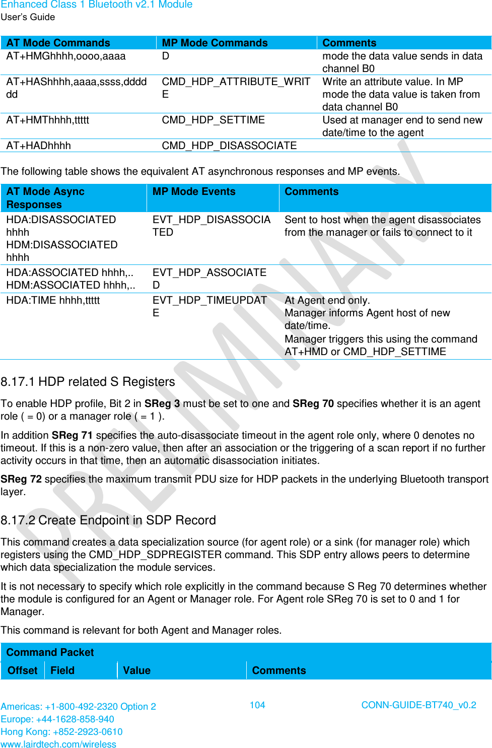
![Enhanced Class 1 Bluetooth v2.1 Module User’s Guide Americas: +1-800-492-2320 Option 2 Europe: +44-1628-858-940 Hong Kong: +852-2923-0610 www.lairdtech.com/wireless 105 CONN-GUIDE-BT740_v0.2 0 LENGTH 22 Fixed 1 CHANNEL 0 Fixed 2 COMMAND [CMD_HDP_ENDPOINT] 3 FLOW_IN ?? Runtime value 4..5 SpecType[2] As per IEEE spec [4]=msb,[5]=lsb Data Specialization code. For example: 100F (4111 dec) for Weigh Scale 6..21 Name[15+1] Null Terminated Name Maximum name size is 15 and name MUST be terminated by a NULL Response Packet Offset Field Value Comments 0 LENGTH 5 Fixed 1 CHANNEL 0 Fixed 2 COMMAND [CMD_HDP_ENDPOINT] 3 FLOW_OUT ?? Runtime value 4 STATUS As appropriate Create multiple data specialization endpoints by submitting this command an appropriate number of times. Internally in the module, the SpecType[2] and Name[15+1] information caches in heap memory until the command CMD_HDP_SDPREGISTER transfers that information into the SDP record for final submission to the underlying Bluetooth stack. 8.17.3 Register SDP record This command registers and activates an HDP related SDP record after creating the endpoints using CMD_HDP_ENDPOINT. Only after this is done can incoming HDP connections be serviced. It is not necessary to specify which role explicitly in the command because S Reg 70 determines whether the module is configured for an Agent or Manager role. For Agent role SReg 70 is set to 0 and 1 for Manager. This command is relevant for both Agent and Manager roles. Command Packet Offset Field Value Comments 0 LENGTH 4 Fixed 1 CHANNEL 0 Fixed 2 COMMAND [CMD_HDP_SDPREGISTER] 3 FLOW_IN ?? Runtime value Response Packet Offset Field Value Comments](https://usermanual.wiki/Laird-Connectivity/BT700.user-manual-BT740-series/User-Guide-1969496-Page-105.png)
![Enhanced Class 1 Bluetooth v2.1 Module User’s Guide Americas: +1-800-492-2320 Option 2 Europe: +44-1628-858-940 Hong Kong: +852-2923-0610 www.lairdtech.com/wireless 106 CONN-GUIDE-BT740_v0.2 0 LENGTH 5 Fixed 1 CHANNEL 0 Fixed 2 COMMAND [CMD_HDP_SDPPREGISTER] 3 FLOW_OUT ?? Runtime value 4 STATUS As appropriate Internally in the module, the SpecType[2] and Name[15+1] information previously cached in heap memory from CMD_HDPENDPOINT commands transfers into an SDP record and submits to the underlying stack. After this a peer is able to see this device offering HDP services. 8.17.4 Bind Agent to a Manager This command binds the Bluetooth address of a manager and an agent data specialization to create an object within the module which a 16 bit handle can subsequently reference, which returns in the response if the command successfully accepts. This command is relevant for Agent role only. Command Packet Offset Field Value Comments 0 LENGTH 14 Fixed 1 CHANNEL 0 Fixed 2 COMMAND [CMD_HDP_BIND] 3 FLOW_IN ?? Runtime value 4..9 BDADDR[] Nap[0,1]:Uap[2]:Lap[3,4,5] Bluetooth address 10.11 SpecType[2] As per IEEE spec [10]=msb,[11]=lsb Data Specialization code. For example: 100F (4111 dec) for Weigh Scale 12.13 AssocTout[2] [12]=msb,[13]=lsb Automatic deassociation timeout. 0 = no timeout Response Packet Offset Field Value Comments 0 LENGTH 7 Fixed 1 CHANNEL 0 Fixed 2 COMMAND [CMD_HDP_BIND] 3 FLOW_OUT ?? Runtime value 4 STATUS As appropriate 5..6 HANDLE[2] [5]=msb,[6]=lsb Handle identifying this instance of data specialization agent The handle returned in the response, if STATUS equals 0, is subsequently used in many commands. If the STATUS byte is not 0, then the HANDLE value i 0.](https://usermanual.wiki/Laird-Connectivity/BT700.user-manual-BT740-series/User-Guide-1969496-Page-106.png)
![Enhanced Class 1 Bluetooth v2.1 Module User’s Guide Americas: +1-800-492-2320 Option 2 Europe: +44-1628-858-940 Hong Kong: +852-2923-0610 www.lairdtech.com/wireless 107 CONN-GUIDE-BT740_v0.2 8.17.5 Associate with Manager This command associates an agent with a manager, using the pre-defined object created using the CMD_HDP_BIND command which returns a handle to represent that object. This command is relevant for Agent role only. Command Packet Offset Field Value Comments 0 LENGTH 6 Fixed 1 CHANNEL 0 Fixed 2 COMMAND [CMD_HDP_ASSOCIATE] 3 FLOW_IN ?? Runtime value 4..5 HANDLE[2] [4]=msb,[5]=lsb Handle identifying an instance of data specialization agent/manager combination RESPONSE PACKET Offset Field Value Comments 0 LENGTH 5 Fixed 1 CHANNEL 0 Fixed 2 COMMAND [CMD_HDP_ASSOCIATE] 3 FLOW_OUT ?? Runtime value 4 STATUS As appropriate The host waits until the response receives before submitting further commands. If association is successful prior to receiving the response, the host sends EVT_ASSOCIATED, which contains the config ID of the MDS configuration that was negotiated and the system ID of the peer. See EVT_ASSOCIATED for further details. If association was not successful, because for example the manager is not in range or the Bluetooth device specified in CMD_HDP_BIND does not offer HDP services, then the EVT_DISASSOCIATED sends to the host prior to the response message. This is shown in the message sequence diagram below.](https://usermanual.wiki/Laird-Connectivity/BT700.user-manual-BT740-series/User-Guide-1969496-Page-107.png)
![Enhanced Class 1 Bluetooth v2.1 Module User’s Guide Americas: +1-800-492-2320 Option 2 Europe: +44-1628-858-940 Hong Kong: +852-2923-0610 www.lairdtech.com/wireless 108 CONN-GUIDE-BT740_v0.2 CMD_HDP_ASSOCIATE(handle)EVT_ASSOCIATED(handle,spec,cfgid,sysid)RSP_HDP_ASSOCIATE(OK)AgentHostCMD_HDP_ASSOCIATE(handle)EVT_DISASSOCIATED(handle)RSP_HDP_ASSOCIATE(not OK)AgentHostSuccessfulAssociationUnsuccessfulAssociation Figure 8-17: Associate sequence diagram 8.17.6 Send Fixed Scan Report to Manager This command associates (if not already associated) and sends a fixed scan report from an agent to the bound manager. The binding specified via the CMD_HDP_BIND command which returns a handle to represent that combination object. This command is relevant for Agent role only, and results in an EVT_HDP_SCANREPORT event at the manager end. A fixed report sends the values for a list of attributes to a manager where the list is predefined in the MDC_ATTR_ATTRIBUTE_VAL_MAP attribute of the NU collection object. Command Packet Offset Field Value Comments 0 LENGTH 9 Fixed 1 CHANNEL 0 Fixed 2 COMMAND [CMD_HDP_SCANREPORT_FIXED] 3 FLOW_IN ?? Runtime value 4..5 HANDLE[2] [4]=msb,[5]=lsb Handle identifying an instance of data specialization agent/manager combination 6..7 PERSONID[2] [6]=msb,[7]=lsb This identifies a person ID which the manager can uses appropriately 8 HOSTCONTEXT XX This echos back in the response and helps the host to keep track of them Response Packet](https://usermanual.wiki/Laird-Connectivity/BT700.user-manual-BT740-series/User-Guide-1969496-Page-108.png)
![Enhanced Class 1 Bluetooth v2.1 Module User’s Guide Americas: +1-800-492-2320 Option 2 Europe: +44-1628-858-940 Hong Kong: +852-2923-0610 www.lairdtech.com/wireless 109 CONN-GUIDE-BT740_v0.2 Offset Field Value Comments 0 LENGTH 8 Fixed 1 CHANNEL 0 Fixed 2 COMMAND [CMD_HDP_SCANREPORT_FIXED] 3 FLOW_OUT ?? Runtime value 4 STATUS As appropriate 5..6 HANDLE[2] [4]=msb,[5]=lsb Echoed back from the command 7 HOSTCONTEXT XX This is echoed back from the command The host waits until the response receives before submitting further commands. If the agent is not associated, then this command first results in an association request and if that is successful the host receives EVT_ASSOCIATED which contains the config ID of the MDS configuration that was negotiated and the system ID of the peer. See EVT_ASSOCIATED for further details. If the agent is already associated, then there is a response as soon as there is acknowledgement from the manager that the scan report was received. If association was not successful, because for example the manager is not in range or the Bluetooth device specified in CMD_HDP_BIND does not offer HDP services, then the EVT_DISASSOCIATED sends to the host prior to the response message. This is shown in the message sequence diagram below (Figure 8-18).](https://usermanual.wiki/Laird-Connectivity/BT700.user-manual-BT740-series/User-Guide-1969496-Page-109.png)

![Enhanced Class 1 Bluetooth v2.1 Module User’s Guide Americas: +1-800-492-2320 Option 2 Europe: +44-1628-858-940 Hong Kong: +852-2923-0610 www.lairdtech.com/wireless 111 CONN-GUIDE-BT740_v0.2 8.17.8 Send VAR Scan Report to Manager This command associates (if not already associated) and then sends a VAR scan report from an agent to the bound manager; the binding is specified via the CMD_HDP_BIND command which returns a handle to represent that combination. This command is relevant for Agent role only, and results in an EVT_HDP_SCANREPORT event at the manager end. A VAR report sends the values for a list of attributes in the NU Collection object to a manager where the host pre-supplies the list. If an attribute does not exist in the NU collection then it is silently ignored. The list is provided by the host via the BLOB data channel for the BLOBID specified in the command (that is, channel number 0x98 plus BLOBID). Command Packet Offset Field Value Comments 0 LENGTH 10 Fixed 1 CHANNEL 0 Fixed 2 COMMAND [CMD_HDP_SCANREPORT_VAR] 3 FLOW_IN ?? Runtime value 4..5 HANDLE[2] [4]=msb,[5]=lsb Handle identifying an instance of data specialization agent/manager combination 6..7 PERSONID[2] [6]=msb,[7]=lsb This identifies a person ID which the manager can use appropriately 8 HOSTCONTEXT XX This echoes back in the response and helps the host to keep track of them 9 BLOBID 0..N See section “Blob Manage” for details of how to send BLOB data using channel 0x98 for blobID=0 etc Response Packet Offset Field Value Comments 0 LENGTH 8 Fixed 1 CHANNEL 0 Fixed 2 COMMAND [CMD_HDP_SCANREPORT_VAR] 3 FLOW_OUT ?? Runtime value 4 STATUS As appropriate 5..6 HANDLE[2] [4]=msb,[5]=lsb Echoed back from the command 7 HOSTCONTEXT XX This echoes back from the command The host waits until the response receives before submitting further commands. If the agent is not associated, then this command first results in an association request and if that is successful the host sends EVT_ASSOCIATED which contains the config ID of the MDS configuration that was negotiated and the system ID of the peer. See EVT_ASSOCIATED for further details.](https://usermanual.wiki/Laird-Connectivity/BT700.user-manual-BT740-series/User-Guide-1969496-Page-111.png)
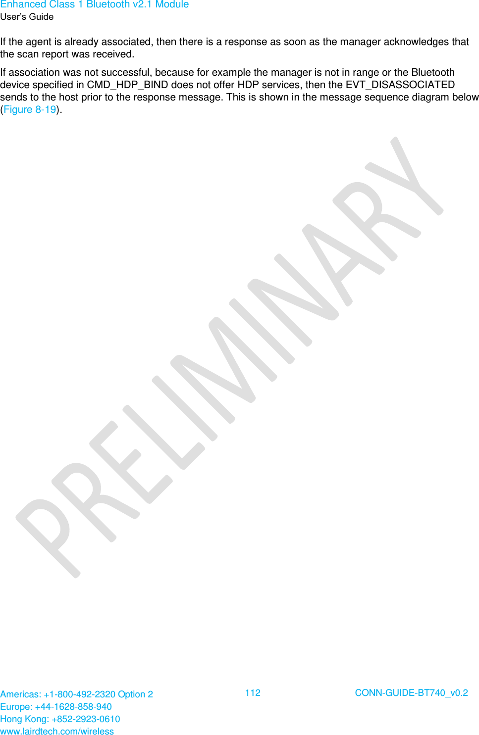
![Enhanced Class 1 Bluetooth v2.1 Module User’s Guide Americas: +1-800-492-2320 Option 2 Europe: +44-1628-858-940 Hong Kong: +852-2923-0610 www.lairdtech.com/wireless 113 CONN-GUIDE-BT740_v0.2 8.17.9 Message Sequence chart for VAR Scan Report Host AgentCMD_HDP_SCANREPORT_VAR(handle,personid,ctx,blobId)DATA CHANNEL[0x98+blobid] {aaaa,bbbb,cccc ....}No priorAssociationandSuccessful Scan Reportdata removed from blob data channelRSP_HDP_SCANREPORT_VAR(OK)EVT_ASSOCIATED(handle,spec,cfgid,sysid)Host AgentCMD_HDP_SCANREPORT_VAR(handle,personid,ctx,blobId)DATA CHANNEL[0x98+blobid] {aaaa,bbbb,cccc ....}data removed from blob data channelPriorAssociationandSuccessful Scan ReportRSP_HDP_SCANREPORT_VAR(OK)Host AgentCMD_HDP_SCANREPORT_VAR(handle,personid,ctx,blobId)DATA CHANNEL[0x98+blobid] {aaaa,bbbb,cccc ....}data removed from blob data channelNo priorAssociationandUnsuccessful Scan ReportRSP_HDP_SCANREPORT_VAR( not OK)EVT_DISASSOCIATED(handle)Host AgentCMD_HDP_SCANREPORT_VAR(handle,personid,ctx,blobId)DATA CHANNEL[0x98+blobid] {aaaa,bbbb,cccc ....}data removed from blob data channelRSP_HDP_SCANREPORT_VAR( not OK)PriorAssociationandUnsuccessful Scan Report Figure 8-19: VAR Scan Report sequence diagram](https://usermanual.wiki/Laird-Connectivity/BT700.user-manual-BT740-series/User-Guide-1969496-Page-113.png)
![Enhanced Class 1 Bluetooth v2.1 Module User’s Guide Americas: +1-800-492-2320 Option 2 Europe: +44-1628-858-940 Hong Kong: +852-2923-0610 www.lairdtech.com/wireless 114 CONN-GUIDE-BT740_v0.2 8.17.10 Read Attribute Value This command is valid for both agent and manager role and reads the value of the attribute specified via the attribute ID and the qualifier ID. The value returns in HDP data channel 0xB0 formatted as described below. Command Packet Offset Field Value Comments 0 LENGTH 10 Fixed 1 CHANNEL 0 Fixed 2 COMMAND [CMD_HDP_ATTRIBUTE_READ] 3 FLOW_IN ?? Runtime value 4..5 HANDLE[2] [4]=msb,[5]=lsb Handle identifying an instance of data specialization agent/manager combination 6..7 ATTRID[2] [6]=msb,[7]=lsb 8..9 QUALIFIERID[2] [8]=msb,[9]=lsb See Note 1 Response Packet Offset Field Value Comments 0 LENGTH 8 Fixed 1 CHANNEL 0 Fixed 2 COMMAND [CMD_HDP_ATTRIBUTE_READ] 3 FLOW_OUT ?? Runtime value 4 STATUS As appropriate 5 HOSTCONTEXT XX This is echoed back from the command 6..7 HANDLE[2] [6]=msb,[7]=lsb Echoed back from the command 1. For manager role, this is the object ID (MDS=0,NU=1 etc) and for Agent please refer to ‘Section Weigh Scale Data Specialization’. As more data specializations are added, the qualifierID specifies appropriately for that specialization. The host shall wait until the response receives before submiting further commands. If the attribute exists, then the data sends in a Logical HDP data packet transported in one or more physical data packets over channel 0xB0. The physical packets of incoming data in channel 0xB0 is viewed as a stream of data making up logical packets. The logical packet format is as follows and is also addressed in a dedicated section later: LEN[2],00,HANDLE[2],ATTRID[2],QUALIFIERID[2],DATA[N] Where LEN[2], HANDLE[2],ATTRID[2],QUALIFIERID[2] are in big endian format (msb sent first) and N is equal to LEN[2]+9. The 00 after the LEN[2] field signifies that this logical packet consists of attribute data.](https://usermanual.wiki/Laird-Connectivity/BT700.user-manual-BT740-series/User-Guide-1969496-Page-114.png)
![Enhanced Class 1 Bluetooth v2.1 Module User’s Guide Americas: +1-800-492-2320 Option 2 Europe: +44-1628-858-940 Hong Kong: +852-2923-0610 www.lairdtech.com/wireless 115 CONN-GUIDE-BT740_v0.2 Since all data is transparently treated in the module, the endienness of DATA[N] should be determined by trial and error with the aid of an HDP manager and finalized to be correct by the time the implementation submits for certification by the Continua Alliance. However, if the attribute data type is a 16 or 32 bit integer/float, then it is little endian. 8.17.11 Write Attribute Value This command is valid for agent role only and writes the value of the attribute, already preloaded in HDP data channel 0xB0, where the attribute ID and the qualifierID is supplied in the command packet. Command Packet Offset Field Value Comments 0 LENGTH 10 Fixed 1 CHANNEL 0 Fixed 2 COMMAND [CMD_HDP_ATTRIBUTE_WRITE] 3 FLOW_IN ?? Runtime value 4..5 HANDLE[2] [4]=msb,[5]=lsb Handle identifying an instance of data specialization agent/manager combination 6..7 ATTRID[2] [6]=msb,[7]=lsb 8..9 QUALIFIERID[2] [8]=msb,[9]=lsb See Note 1 Response Packet Offset Field Value Comments 0 LENGTH 8 Fixed 1 CHANNEL 0 Fixed 2 COMMAND [CMD_HDP_ATTRIBUTE_WRITE] 3 FLOW_OUT ?? Runtime value 4 STATUS As appropriate 5 HOSTCONTEXT XX This echoes back from the command 6..7 HANDLE[2] [6]=msb,[7]=lsb Echoes back from the command 1. For manager role, this is the object ID (MDS=0,NU=1 etc). As more data specializations are added, the qualifierID specifies appropriately for that specialization. The host waits until the response receives before submiting further commands. If the attribute exists, then the data moves from channel 0xB0 to the attribute container variable. If the attribute does not exist, then the data discards. All the data in the channel is treated as the data for the attribute; that is, there is no qualifying information affixed to the data. In addition, if the attribute exists but the data length does not match that of the attribute, then the write fails (with an appropriate error code) and the data in the channel is discarded. Since all data is transparently treated in the module, the endienness of DATA[N] should be determined by trial and error with the aid of a HDP manager and finalized to be correct by the time the implementation is submitted for certification by the Continua Alliance. However, if the attribute data type is a 16 or 32 bit integer/float, then it will be little endian.](https://usermanual.wiki/Laird-Connectivity/BT700.user-manual-BT740-series/User-Guide-1969496-Page-115.png)
![Enhanced Class 1 Bluetooth v2.1 Module User’s Guide Americas: +1-800-492-2320 Option 2 Europe: +44-1628-858-940 Hong Kong: +852-2923-0610 www.lairdtech.com/wireless 116 CONN-GUIDE-BT740_v0.2 8.17.12 Set Date and Time This command is valid for manager role only and updates the date and time in the associated agent identified by the handle. When any HDP manager sends a time update to an agent, it results in an EVT_HDP_UPDATE event to the host of that agent. Command Packet Offset Field Value Comments 0 LENGTH 14 Fixed 1 CHANNEL 0 Fixed 2 COMMAND [CMD_HDP_SET_TIME] 3 FLOW_IN ?? Runtime value 4..5 HANDLE[2] [4]=msb,[5]=lsb Handle identifying an instance of data specialization agent/manager combination 6..13 DATETIME[8] Ccyymmddhhssnnxx See Note 1 Response Packet Offset Field Value Comments 0 LENGTH 14 Fixed 1 CHANNEL 0 Fixed 2 COMMAND [CMD_HDP_SET_TIME] 3 FLOW_OUT ?? Runtime value 4 STATUS As appropriate 1. This command supplies the date/time information as a string of 8 bytes “ccyymmddhhssnnxx” where each byte is as follows: CC Century e.g for 2011 the value shall be 0x14 YY Year e.g for 2011 the value shall be 0x0B MM Month e.g for January the value shall be 0x01 and for say December 0x0C DD Day e.g for 31 the value shall be 0x1F (0 is illegal value) HH Hour e.g for 6:45pm the value shall be 0x12 NN Minutes e.g for 6:45pm the value shall be 0x2D XX fraction This is a fraction of a seconds in hundredths of unit. Valid 00..0x63 (99 For example the date and time “2 Feb 2011, 16:43:33.78” sends at the string “150C020C102D214E The host waits until the response receives before submitting further commands.](https://usermanual.wiki/Laird-Connectivity/BT700.user-manual-BT740-series/User-Guide-1969496-Page-116.png)
![Enhanced Class 1 Bluetooth v2.1 Module User’s Guide Americas: +1-800-492-2320 Option 2 Europe: +44-1628-858-940 Hong Kong: +852-2923-0610 www.lairdtech.com/wireless 117 CONN-GUIDE-BT740_v0.2 8.17.13 Disassociate From Manager This command disassociates an agent identified by the handle specified in the command from a manager. This command is relevant for Agent role only. Command Packet Offset Field Value Comments 0 LENGTH 6 Fixed 1 CHANNEL 0 Fixed 2 COMMAND [CMD_HDP_DISASSOCIATE] 3 FLOW_IN ?? Runtime value 4..5 HANDLE[2] [4]=msb,[5]=lsb Handle identifying an instance of data specialization agent/manager combination Response Packet Offset Field Value Comments 0 LENGTH 5 Fixed 1 CHANNEL 0 Fixed 2 COMMAND [CMD_HDP_DISASSOCIATE] 3 FLOW_OUT ?? Runtime value 4 STATUS As appropriate The host waits until the response receives before submitting further commands. The response sends immediately after initiating the disassociation and when the procedure is complete, an EVT_DISASSOCIATED is sent to the host as shown in the message sequence diagram below (Figure 8-20). AgentHostRSP_HDP_DISASSOCIATE(OK)CMD_HDP_DISASSOCIATE(handle)EVT_DISASSOCIATED(handle) Figure 8-20: Disassociate sequence diagram](https://usermanual.wiki/Laird-Connectivity/BT700.user-manual-BT740-series/User-Guide-1969496-Page-117.png)
![Enhanced Class 1 Bluetooth v2.1 Module User’s Guide Americas: +1-800-492-2320 Option 2 Europe: +44-1628-858-940 Hong Kong: +852-2923-0610 www.lairdtech.com/wireless 118 CONN-GUIDE-BT740_v0.2 9 MODULE EVENTS This section describes all module originated asynchronous events in detail and is specified via the EVT_ID field of all event packets. The description for each event below is in the form of an event packet tables. Each event has a unique EVT_ID value in the range 129 to 255 (0x81 to 0xFF), 0x80 is reserved. The actual value of EVT_ID in the Value column is described as [Descriptive_Name] where “Descriptive_Name” can be found in a ‘C’ header file, obtained on request from Laird. 9.1 Inquiry Events This group of events is inquiry related. 9.1.1 Inquiry Result This event sends the inquiry response from a peer as a result of an inquiry request. Event Packet Offset Field Value Comments 0 LENGTH 13 1 CHANNEL 0 2 EVENT [EVT_ INQUIRY_RESULT] 3 FLOW_OUT ?? Runtime value 4..9 BDADDR[6] Nap[0,1]:Uap[2]:Lap[3,4,5] Bluetooth address of responding device 10..12 DEVCLASS[3] 0x000000 .. 0xFFFFFF Device class of responding device 9.2 Information Events This group of events conveys information about the module, for example to status. 9.2.1 Unknown Command This event informs the host that a received command had an unknown COMMAND value. The COMMAND value echoes in offset 4. Event Packet Offset Field Value Comments 0 LENGTH 1 CHANNEL 2 EVENT [EVT_UNKNOWN_COMMAND] 3 FLOW_OUT ?? Runtime value 4 Command xx CMD_ID value echoed from command](https://usermanual.wiki/Laird-Connectivity/BT700.user-manual-BT740-series/User-Guide-1969496-Page-118.png)
![Enhanced Class 1 Bluetooth v2.1 Module User’s Guide Americas: +1-800-492-2320 Option 2 Europe: +44-1628-858-940 Hong Kong: +852-2923-0610 www.lairdtech.com/wireless 119 CONN-GUIDE-BT740_v0.2 9.2.2 Status This event asynchronously sends current status to the host. This event is sent to the host after power up to inform the host that the module is ready and operational. You can also obtain the information contained in this message by sending the CMD_GET_MODES command. Event Packet Offset Field Value Comments 0 LENGTH 8 1 CHANNEL 0 2 EVENT [EVT_ STATUS] 3 FLOW_OUT ?? Runtime value 4 STATUS OK or INVALID_LICENSE 5 DISCMODE 0..1 1 for discoverable mode 6 CONNMODE 0..1 Bit 0: 1 for connectable mode In future bit 1, if set, may indicate that incoming SPP connections are auto accepted 7 SECMODE 12..15 12 = SSP + IO_CAP_NO_INPUT_NO_OUTPUT 13 = SSP + IO_CAP_DISPLAY_YES_NO 14 = SSP + IO_CAP_KEYBOARD_ONLY 15 = SSP + IO_CAP_DISPLAY_ONLY 9.2.3 Invalid Packet Size This event informs the host that a command packet was received whose length does not match the size of the structure published in the interface header file BmHostProtocol.h. Event Packet Offset Field Value Comments 0 LENGTH 7 1 CHANNEL 0 2 EVENT [EVT_INVALID_PKTSIZE] 3 FLOW_OUT ?? Runtime value 4 CMD_ID 1..127 Echoed from the command 5 ACT_SIZE A Actual size of the packet 6 DES_SIZE D Desired size of the packet](https://usermanual.wiki/Laird-Connectivity/BT700.user-manual-BT740-series/User-Guide-1969496-Page-119.png)
![Enhanced Class 1 Bluetooth v2.1 Module User’s Guide Americas: +1-800-492-2320 Option 2 Europe: +44-1628-858-940 Hong Kong: +852-2923-0610 www.lairdtech.com/wireless 120 CONN-GUIDE-BT740_v0.2 9.3 Connection Events This group of events are connection related. 9.3.1 Connection Setup This event informs the host that a remote device is requesting a connection. The host responds with a CMD_CONNECTION_SETUP with an accept or reject flag. Event Packet Offset Field Value Comments 0 LENGTH 12 1 CHANNEL 0 2 EVENT [EVT_ CONNECTION_SETUP] 3 FLOW_OUT ?? Runtime value 4..9 BDADDR[6] Nap[0,1]:Uap[2]:Lap[3,4,5] Bluetooth address of device requesting connection 10..11 UUID[] Server profile UUID the peer wishes to connect to 0x1101 = SPP 0x1124 = HID DEVICE The UUID field tells the host which server profile the peer wishes to connect to. 9.3.2 Incoming Connection This event informs the host that an incoming connection established. Event Packet Offset Field Value Comments 0 LENGTH 13 1 CHANNEL 0 2 EVENT [EVT_ CONNECTION_SETUP] 3 FLOW_OUT ?? Runtime value 4 CHANNEL 1..254 Channel ID to be used to send/receive data, see note 1 for channel number allocation. 5..10 BDADDR[6] Nap[0,1]:Uap[2]:Lap[3,4,5] Bluetooth address of device requesting connection 11..12 UUID[] Server profile UUID the peer wishes to connect to 0x1101 = SPP 0x1124 = HID DEVICE The UUID field tells the host which server profile the peer has connected to.](https://usermanual.wiki/Laird-Connectivity/BT700.user-manual-BT740-series/User-Guide-1969496-Page-120.png)
![Enhanced Class 1 Bluetooth v2.1 Module User’s Guide Americas: +1-800-492-2320 Option 2 Europe: +44-1628-858-940 Hong Kong: +852-2923-0610 www.lairdtech.com/wireless 121 CONN-GUIDE-BT740_v0.2 1. Channel number allocation is as follows: Profile Channel ID Range Command Parser 0x00 SPP 0x1 .. 0x7 HID DEVICE(Canned) 0x20 HID HOST(Raw) 0x90 .. 0x97 HID DEVICE(Raw) 0xA0 BLOB 0x98 .. 0x9F HDP 0xB0..0xB1 (B1 is continuation channel) Enhanced Inquiry Response 0xF0 9.3.3 Disconnect This event informs the host that a connection was dropped by the remote device. Event Packet Offset Field Value Comments 0 LENGTH 6 1 CHANNEL 0 2 EVENT [EVT_ DISCONNECT] 3 FLOW_OUT ?? Runtime value 4 CHANNEL 1..7 Channel number 5 REASON 0..255 As per the table below The Bluetooth specification specifies the Reason value. Please note that values in the range 0xF0 to 0xFF are custom values defined for this implementation and do not appear in the Bluetooth specification. 0x01 … 0x3F 0xFF See header file MPSTATUS.H which is supplied on request. High probability that the remote device went out range for longer than the link supervision timeout or was powered down.](https://usermanual.wiki/Laird-Connectivity/BT700.user-manual-BT740-series/User-Guide-1969496-Page-121.png)
![Enhanced Class 1 Bluetooth v2.1 Module User’s Guide Americas: +1-800-492-2320 Option 2 Europe: +44-1628-858-940 Hong Kong: +852-2923-0610 www.lairdtech.com/wireless 122 CONN-GUIDE-BT740_v0.2 9.3.4 Modem Status This event conveys modem status signals originating from the peer device for an SPP connection. Event Packet Offset Field Value Comments 0 LENGTH 6 1 CHANNEL 0 2 EVENT [EVT_ MODEM_STATUS] 3 FLOW_OUT ?? Runtime value 4 CHANNEL 1..7 Channel ID of an open SPP channel 5 MODEMSIG Bit Mask Bit 0: DSR state Bit 1: CTS state Bit 2: DCD state Bit 3: RI state 6 BREAKSIG 0 For future implementation 9.4 Miscellaneous Events 9.4.1 Link Key This event informs the host that a new link key was created for the device indicated and the result of writing to the ROLLING database. Event Packet Offset Field Value Comments 0 LENGTH 11 1 CHANNEL 0 2 EVENT [EVT_ LINK_KEY] 3 FLOW_OUT ?? Runtime value 4..9 BDADDR[6] Nap[0,1]:Uap[2]:Lap[3,4,5] Bluetooth address of paired device 10 DBRESULT 0: Success Any other value is a failure and the reason is a STATUS value as per MPSTATUS.H](https://usermanual.wiki/Laird-Connectivity/BT700.user-manual-BT740-series/User-Guide-1969496-Page-122.png)
![Enhanced Class 1 Bluetooth v2.1 Module User’s Guide Americas: +1-800-492-2320 Option 2 Europe: +44-1628-858-940 Hong Kong: +852-2923-0610 www.lairdtech.com/wireless 123 CONN-GUIDE-BT740_v0.2 9.4.2 Link Key Ex This event sends to the host when CMD_TRUSTED_DB_ISTRUSTED processes, a link key for that peer device exists, and S Register 47 is set to 1. It conveys the link key along with the Bluetooth address to the host. Event Packet Offset Field Value Comments 0 LENGTH 30 1 CHANNEL 0 2 EVENT [EVT_ LINK_KEY_EX] 3 FLOW_OUT ?? Runtime value 4..9 BDADDR[6] Nap[0,1]:Uap[2]:Lap[3,4,5] Bluetooth address of paired device 10..25 KEY[16] 16 byte array The link key 26..29 RFU[4] 4 byte array Reserved for future 9.4.3 Pin Code Request This event informs the host that a remote device requested a pairing and the procedure requires a pin code to complete. Event Packet Offset Field Value Comments 0 LENGTH 10 1 CHANNEL 0 2 EVENT [EVT_ PINCODE_REQUEST] 3 FLOW_OUT ?? Runtime value 4..9 BDADDR[6] Nap[0,1]:Uap[2]:Lap[3,4,5] Bluetooth address of pairing device The host sends a CMD_PINCODE in response to this event. This event receives if ‘accept pairing while in connectable mode’ enables via S Register 15. 9.4.4 Simple Pairing This event informs the host that a simple pairing procedure is in progress and the ‘action’ byte in offset 10 tells the host what to do. Event Packet Offset Field Value Comments 0 LENGTH 15 1 CHANNEL 0 2 EVENT [EVT_ SIMPLE_PAIRING]](https://usermanual.wiki/Laird-Connectivity/BT700.user-manual-BT740-series/User-Guide-1969496-Page-123.png)
![Enhanced Class 1 Bluetooth v2.1 Module User’s Guide Americas: +1-800-492-2320 Option 2 Europe: +44-1628-858-940 Hong Kong: +852-2923-0610 www.lairdtech.com/wireless 124 CONN-GUIDE-BT740_v0.2 Event Packet Offset Field Value Comments 3 FLOW_OUT ?? Runtime value 4..9 BDADDR[6] Nap[0,1]:Uap[2]:Lap[3,4,5] Bluetooth address of pairing device 10 action 0..3 See description below 11..14 actionval 4 bytes See description below The host reacts to this event based on the value of the ‘action’ byte in offset 10 as follows: Action :: 0 This informs the host that a simple pairing procedure has just been completed and ‘actionval’ is 00000001 for success and 00000000 for fail. The host shall NOT react to this event with the CNF_SIMPLE_PAIRING packet. Action :: 1 This informs the host that a simple pairing procedure is in progress and all it will do is display the passcode in ‘actionval’ as a six digital decimal number WITH leading zeroes. The host shall NOT react to this event with the CNF_SIMPLE_PAIRING packet. Action :: 2 This informs the host that a simple pairing procedure is in progress and it displays the passcode in ‘actionval’ as a 6 digital decimal number WITH leading zeros. The host reacts to this event with the CNF_SIMPLE_PAIRING packet with a 00000000 value for No and a non-00000000 value for Yes. The former value, if the host deems that the passcode is not acceptable, and the latter if acceptable. Action :: 3 This informs the host that a simple pairing procedure is in progress and the module is expecting a passcode from the host embedded in a CNF_SIMPLE_PAIRING packet. The host shall react to this event with the CNF_SIMPLE_PAIRING packet with a passcode value. The passcode in the CNF_SIMPLE_PAIRING is either obtained by reading the display on the peer device, or if the peer device is also a keyboard only, then the same random 6 digit value (with leading 0s) that is entered at both ends. 9.4.5 Local Friendly Name This event sends a fragment of the local friendly name to the host. The maximum length of the fragment is 10, so at least 3 of these events are required to convey a local friendly name, if it has the maximum length of 30. Event Packet Offset Field Value Comments 0 LENGTH 16 1 CHANNEL 0 2 EVENT [EVT_LCL_FNAME] 3 FLOW_OUT ?? Runtime value 4 INDEX 0..29 Start index into the string 5 LEN 1..10 Number of valid characters in the NAME[] field that follows](https://usermanual.wiki/Laird-Connectivity/BT700.user-manual-BT740-series/User-Guide-1969496-Page-124.png)
![Enhanced Class 1 Bluetooth v2.1 Module User’s Guide Americas: +1-800-492-2320 Option 2 Europe: +44-1628-858-940 Hong Kong: +852-2923-0610 www.lairdtech.com/wireless 125 CONN-GUIDE-BT740_v0.2 6..15 NAME[10] Xx xx xx xx The name fragment](https://usermanual.wiki/Laird-Connectivity/BT700.user-manual-BT740-series/User-Guide-1969496-Page-125.png)
![Enhanced Class 1 Bluetooth v2.1 Module User’s Guide Americas: +1-800-492-2320 Option 2 Europe: +44-1628-858-940 Hong Kong: +852-2923-0610 www.lairdtech.com/wireless 126 CONN-GUIDE-BT740_v0.2 9.4.6 Remote Friendly Name This event sends a fragment of the remote friendly name to the host. The maximum length of the fragment is 10, so at least 25 of these events are required to convey a remote friendly name, if it has the maximum length of 248. Event Packet Offset Field Value Comments 0 LENGTH 16 1 CHANNEL 0 2 EVENT [EVT_REM_FNAME] 3 FLOW_OUT ?? Runtime value 4 INDEX 0..247 Start index into the string 5 LEN 1..10 Number of valid characters in the NAME[] field that follows 6..15 NAME[10] Xx xx xx xx The name fragment 9.4.7 Event_ADC This event returns after a CMD_GET_IO command where the analogID is set to either 1 or 2. In these circumstances the module digitises the voltage on either Analogue0 or Analogue 1 and reports the value as an eight bit hex number. Therefore the value shown in the ValMSB field should always be zero. Event Packet Offset Field Value Comments 0 LENGTH 16 1 CHANNEL 0 2 EVENT [EVT_ADC] 3 FLOW_OUT ?? Runtime value 4 analogId 1..2 1 – AIO0 2 – AIO1 5 valMSB 0 MSB of 16 bit digitised input 6 valLSB 0..FF LSB of 16 bit digitised inoput](https://usermanual.wiki/Laird-Connectivity/BT700.user-manual-BT740-series/User-Guide-1969496-Page-126.png)
![Enhanced Class 1 Bluetooth v2.1 Module User’s Guide Americas: +1-800-492-2320 Option 2 Europe: +44-1628-858-940 Hong Kong: +852-2923-0610 www.lairdtech.com/wireless 127 CONN-GUIDE-BT740_v0.2 10 HDP PROFILE RELATED EVENTS 10.1 Associated This event informs the host that an agent associated with the manager and contained the handle, data specialization nominal code, device config ID (as per the IEEE standard) and a unique 8 byte identification number for the agent (or manager). It is relevant for both agent and manager roles. EVENT PACKET Offset Field Value Comments 0 LENGTH 11 1 CHANNEL 0 2 EVENT [EVT_HDP_ASSOCIATED] 3 FLOW_OUT ?? Runtime value 4 ROLE 00=Agent, 01==Manager 5..6 HANDLE[2] [5]=msb, [6]=lsb Handle of the agent 7..8 SPECTYPE[2] [7]=msb, [8]=lsb Data specialization nominal code. E.g 4111 (0x100F) for Weigh Scale 9..10 DEVCFGID[2] [9]=msb, [10]=lsb The negotiated config ID. Will be defined in the appropriate IEEE data specialization standard. 11..18 SYSID[8] 8 bytes This is a system ID which is unique to the agent instant. 10.2 Deassociated This event informs the host that an agent has disassociated from the manager and contains the handle of the agent. It is relevant for both agent and manager roles. Event Packet Offset Field Value Comments 0 LENGTH 7 1 CHANNEL 0 2 EVENT [EVT_HDP_DISASSOCIATED] 3 FLOW_OUT ?? Runtime value 4 ROLE 00=Agent, 01==Manager 5..6 HANDLE[2] [5]=msb, [6]=lsb Handle of the agent](https://usermanual.wiki/Laird-Connectivity/BT700.user-manual-BT740-series/User-Guide-1969496-Page-127.png)
![Enhanced Class 1 Bluetooth v2.1 Module User’s Guide Americas: +1-800-492-2320 Option 2 Europe: +44-1628-858-940 Hong Kong: +852-2923-0610 www.lairdtech.com/wireless 128 CONN-GUIDE-BT740_v0.2 10.3 Time Update This event generates for an agent role only and informs the host that the agent received an updated date and time from the manager. Event Packet Offset Field Value Comments 0 LENGTH 11 1 CHANNEL 0 2 EVENT [EVT_HDP_TIMEUPDATE] 3 FLOW_OUT ?? Runtime value 4 ROLE 00=Agent, 01==Manager 5..6 HANDLE[2] [5]=msb, [6]=lsb Handle of the agent 11..14 DATETIME[8] ccyymmddhhssnnxx See Note 1 1. The date/time information is supplied in this command as a string of 8 bytes “ccyymmddhhssnnxx” where each byte is as follows: CC Century e.g for 2011 the value shall be 0x14 YY Year e.g for 2011 the value shall be 0x0B MM Month e.g for January the value shall be 0x01 and for say December 0x0C DD Day e.g for 31 the value shall be 0x1F (0 is illegal value) HH Hour e.g for 6:45pm the value shall be 0x12 NN Minutes e.g for 6:45pm the value shall be 0x2D XX fraction This is a fraction of a seconds in hundredths of unit. Valid 00..0x63 (99 For example the date and time “2 Feb 2011, 16:43:33.78” shall be sent at the string “150C020C102D214E” 11 DEBUG EVENTS 11.1 Debug Packet This event conveys debugging information to the host, and is available in engineering/beta builds only. Event Packet Offset Field Value Comments 0 LENGTH 16 1 CHANNEL 0 2 EVENT [EVT_DEBUG_PACKET] 3 FLOW_OUT ?? Runtime value 4 TYPE_FLAG XX Bit 0: First Packet Bit 1: Last Packet Bit 2..5: Reserved Bit 6..7: Message Type 5..15 DATA[] Contains Ascii data String conveying message](https://usermanual.wiki/Laird-Connectivity/BT700.user-manual-BT740-series/User-Guide-1969496-Page-128.png)
![Enhanced Class 1 Bluetooth v2.1 Module User’s Guide Americas: +1-800-492-2320 Option 2 Europe: +44-1628-858-940 Hong Kong: +852-2923-0610 www.lairdtech.com/wireless 129 CONN-GUIDE-BT740_v0.2 11.2 Malloc Statistics This event conveys pool malloc statistics to the host and is available in engineering/beta builds only. Event Packet Offset Field Value Comments 0 LENGTH 16 1 CHANNEL 0 2 EVENT [EVT_DEBUG_PACKET] 3 FLOW_OUT ?? Runtime value 4..5 ELSIZE[2] 0..N Pool Element Size 6..7 NUMELS[2] 0..N Number of elements 8..9 TAKEN[2] 0..N Number of elements taken 10..11 MAXTKN[2] 0..N Tide mark for taken 12..13 OVFLO[2] 0..N Number of allocations from next bigger element because this size is maxed out 12 DATA CHANNELS This section provides details of some data channels which require further explanation. 12.1 HDP Data Channels 12.1.1 Host to Module Direction Channels B0 and B1 upload attribute data which then transfers to the appropriate data specialization data variable on receipt of a CMD_HDP_ATTRUBUTE_WRITE command. The host ensures that the correct number of bytes for that attribute accumulate in the channel, as length is the only validation performed on the data; the module does not interpret the data in any way besides length. With regards to the endienness of the data, this shall be determined by trial and error using an appropriate certified HDP manager. It is entirely possible that an attribute can be defined which contains data requiring more than 253 bytes. A data packet cannot contain data more than 253 bytes so this could present a problem. The solution to that is both channels B0 and B1 write into a buffer in the module to allow the host to accumulate attribute data using several data packets. However when using B0 it always first deletes any data already accumulated in the buffer and then writes to that buffer, whereas writing to channel B1 shall always append the data to the buffer. 12.1.2 Module to Host Direction Channels B0 and B1 send logical HDP packets to the host. Channel B0 is always the first fragment of the logical packet and subsequent fragments send in channel B1. This means that when the host receives a packet on channel B0, it deletes all data accumulated for an existing ongoing logical packet.](https://usermanual.wiki/Laird-Connectivity/BT700.user-manual-BT740-series/User-Guide-1969496-Page-129.png)
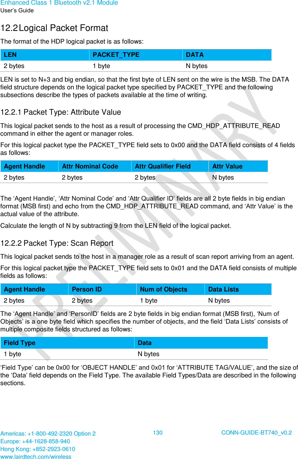
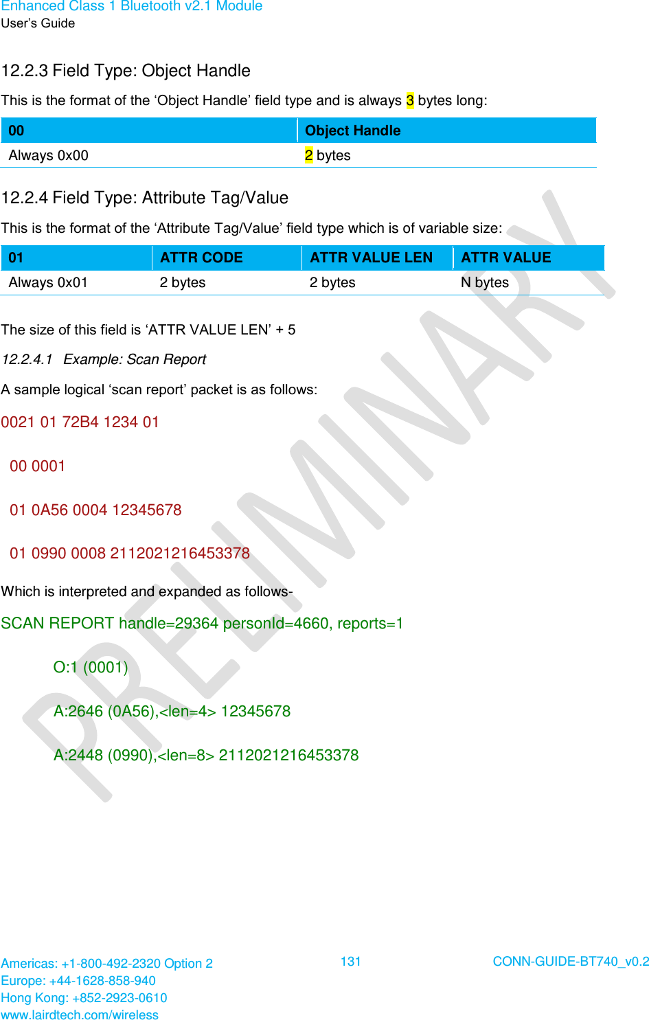
![Enhanced Class 1 Bluetooth v2.1 Module User’s Guide Americas: +1-800-492-2320 Option 2 Europe: +44-1628-858-940 Hong Kong: +852-2923-0610 www.lairdtech.com/wireless 132 CONN-GUIDE-BT740_v0.2 12.2.5 Sample code to interpret a ScanReport logical packet The following code shows how a logical ‘Scan Report’ packet could be separated into its constituent parts: void PrintScanReport(unsigned char *pRxPkt, unsigned nRxPktLen) { char baMsg[512]; uint16 nHandle; uint16 nPersonId; uint16 nObject; uint16 nAttrId; uint16 nAttrLen; uint8 *pSrc; char *pMsg; nHandle = (pRxPkt[3]<<8)+pRxPkt[4]; nPersonId = (pRxPkt[5]<<8)+pRxPkt[6]; printf(baMsg,"SCAN REPORT handle=%d personId=%d, reports=%d", nHandle, nPersonId, pRxPkt[7]); pSrc = &pRxPkt[8]; while(pSrc < &pRxPkt[nRxPktLen]) { switch(*pSrc) { case HDP_SCANREPORT_INFOTYPE_OBJECT: /* 0x00 */ pSrc++; if( pSrc >= &pRxPkt[nRxPktLen] ) { printf("INSUFFICIENT LENGTH -- ABORT display of msg"); break; } nObject = (pSrc[0]<<8)+pSrc[1]; printf(" O:%d (%04X)",nObject,nObject); pSrc+=2; break; case HDP_SCANREPORT_INFOTYPE_ATTRIBUTE: /* 0x01 */ pMsg = baMsg; pSrc++; nAttrId = (pSrc[0]<<8)+pSrc[1]; pSrc+=2; nAttrLen = (pSrc[0]<<8)+pSrc[1]; pSrc+=2; if( &pSrc[nAttrLen] > &pRxPkt[nRxPktLen] )](https://usermanual.wiki/Laird-Connectivity/BT700.user-manual-BT740-series/User-Guide-1969496-Page-132.png)
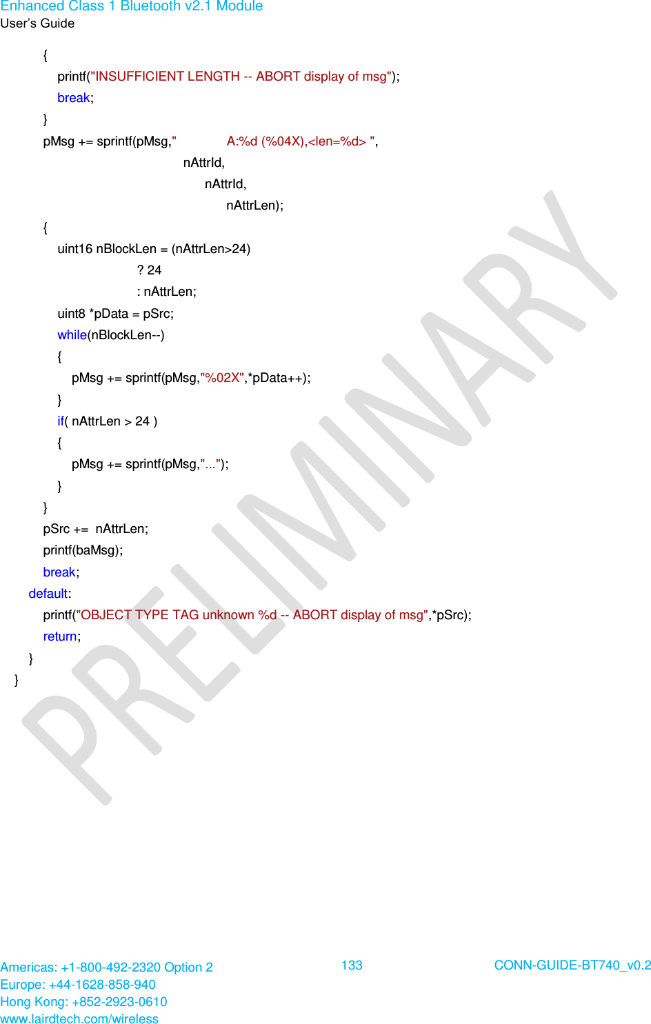
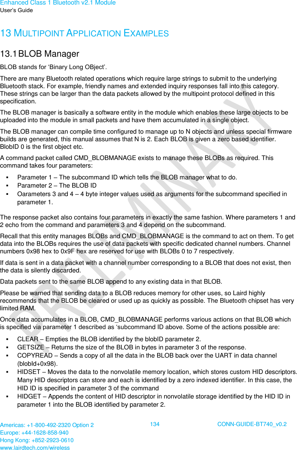
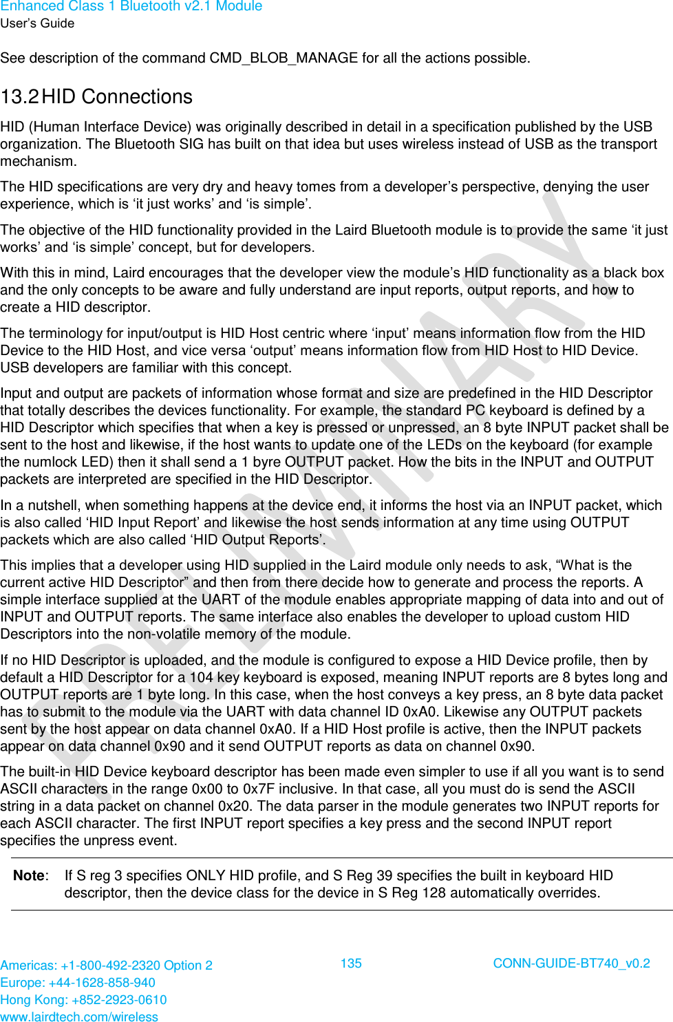
![Enhanced Class 1 Bluetooth v2.1 Module User’s Guide Americas: +1-800-492-2320 Option 2 Europe: +44-1628-858-940 Hong Kong: +852-2923-0610 www.lairdtech.com/wireless 138 CONN-GUIDE-BT740_v0.2 13.6.3 Message Sequence Chart HostHost ModuleCMD_STORE_SREGCMD_STORE_SREGCMD_RESET CMD_RESETModule in factory default modeModule in factory default modeEnable HDP+SPP ProfileEnable Agent or Manager RoleSave SReg to NonVol MemoryReset to make SReg EffectiveCMD_WRITE_SREG [46 00000000]CMD_WRITE_SREG [03 00000005]CMD_WRITE_SREG [46 00000001]CMD_WRITE_SREG [03 00000005]Pair the devicesCMD_PAIR_INITIATE [ addr ]EVT_SIMPLE_PAIRING [ 00000001] EVT_SIMPLE_PAIRING [ 00000001]EVT_LINK_KEY [ addr ] EVT_LINK_KEY [ addr ]RSP_PAIR_INITIATE [OK]AGENT MANAGERModuleCMD_HDP_ENDPOINT [100F 7363616C6500..]CMD_HDP_SDPREGISTERRegister and activate HDPWeigh Scale Sink Role at ManagerCMD_BIND [addr 100F]CMD_HDP_ENDPOINT [100F 7363616C6500..] Register and activate HDPWeigh Scale Source Rolesat Agent, and also bind Agent to ManagerBluetooth AddressCMD_HDP_SDPREGISTERRSP_BIND [hhhh]AssociateCMD_ASSOCIATE [hhhh]EVT_ASSOCIATED [h1h1 100F 05DC S...S] EVT_ASSOCIATED [h2h2 100F 05DC S...S]Continued on next pageAssociatedAssociated](https://usermanual.wiki/Laird-Connectivity/BT700.user-manual-BT740-series/User-Guide-1969496-Page-138.png)
![Enhanced Class 1 Bluetooth v2.1 Module User’s Guide Americas: +1-800-492-2320 Option 2 Europe: +44-1628-858-940 Hong Kong: +852-2923-0610 www.lairdtech.com/wireless 139 CONN-GUIDE-BT740_v0.2 HostHost ModuleModuleAGENT MANAGERAssociated AssociatedSend a FIXED Scan ReportCMD_HDP_SCANREPORT_FIXED [h1h1 pppp]BLOB 0 CHANNEL 98[0A56 0990 0996] Send a VAR Scan Reportconsisting of 3 attribute0A56, 0990, 0996CMD_HDP_SCANREPORT_VAR [h1h1 pppp]Send a Time Updatefrom Manager to AgentCMD_HDP_SET_TIME [h2h2 tttttttt]EVT_HDP_TIMEUPDATE [h1h1 tttttttt]HDP DATA CHANNEL B0[12345678]CMD_HDP_ATTRIBUTE_WRITE [h1h1 0A56 0000]CMD_HDP_ATTRIBUTE_READ[h1h1 0A56 0000]HDP DATA CHANNEL B0LOGICAL PACKET TYPE 01[LLLL 01 h2h2 pppp [attr data]]HDP DATA CHANNEL B0LOGICAL PACKET TYPE 01[LLLL 01 h2h2 pppp [attr data]]HDP DATA CHANNEL B0LOGICAL PACKET TYPE 00[LLLL 00 h2h2 attr qqqq dddd]Read Attr from Agent MDSAttribute 0A56 (2436 dec) (Can be done only whenassociated)Write a value into an AgentAttribute 0A56 (2646 dec) (Can also be done whennot associated)Read AgentAttribute 0A56 (2646 dec) (Can also be done whennot associated)CMD_HDP_ATTRIBUTE_READ[h2h2 0984 0000]HDP DATA CHANNEL B0LOGICAL PACKET TYPE 00[LLLL 00 h2h2 attr qqqq dddd]CMD_DISASSOCIATE [hhhh]EVT_DISASSOCIATED [h1h1] EVT_DISASSOCIATED [h2h2]DisassociateDisassociatedDisassociated](https://usermanual.wiki/Laird-Connectivity/BT700.user-manual-BT740-series/User-Guide-1969496-Page-139.png)
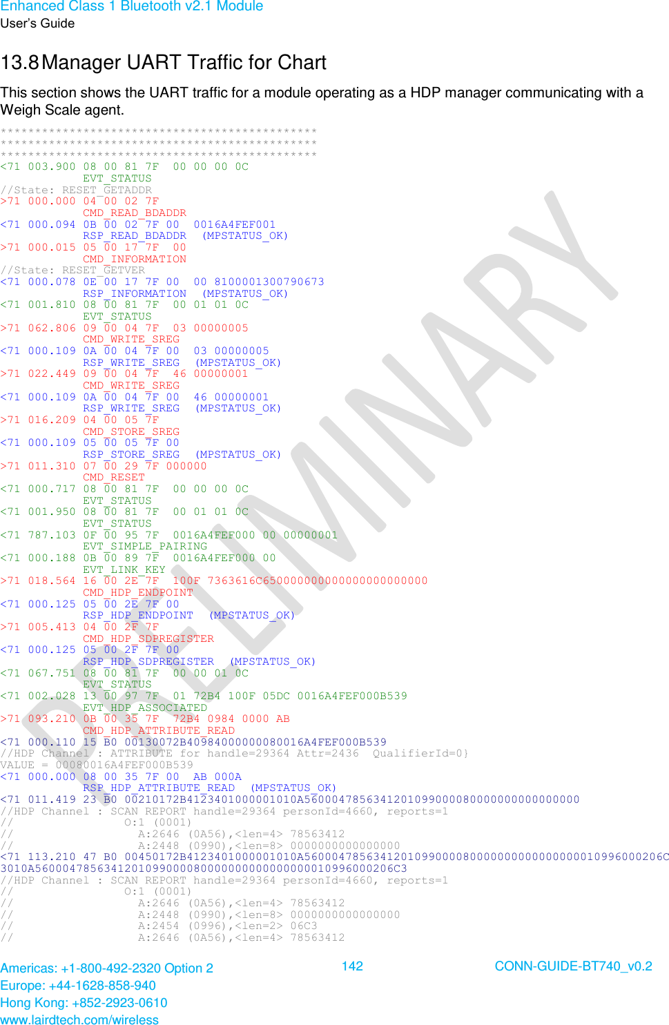
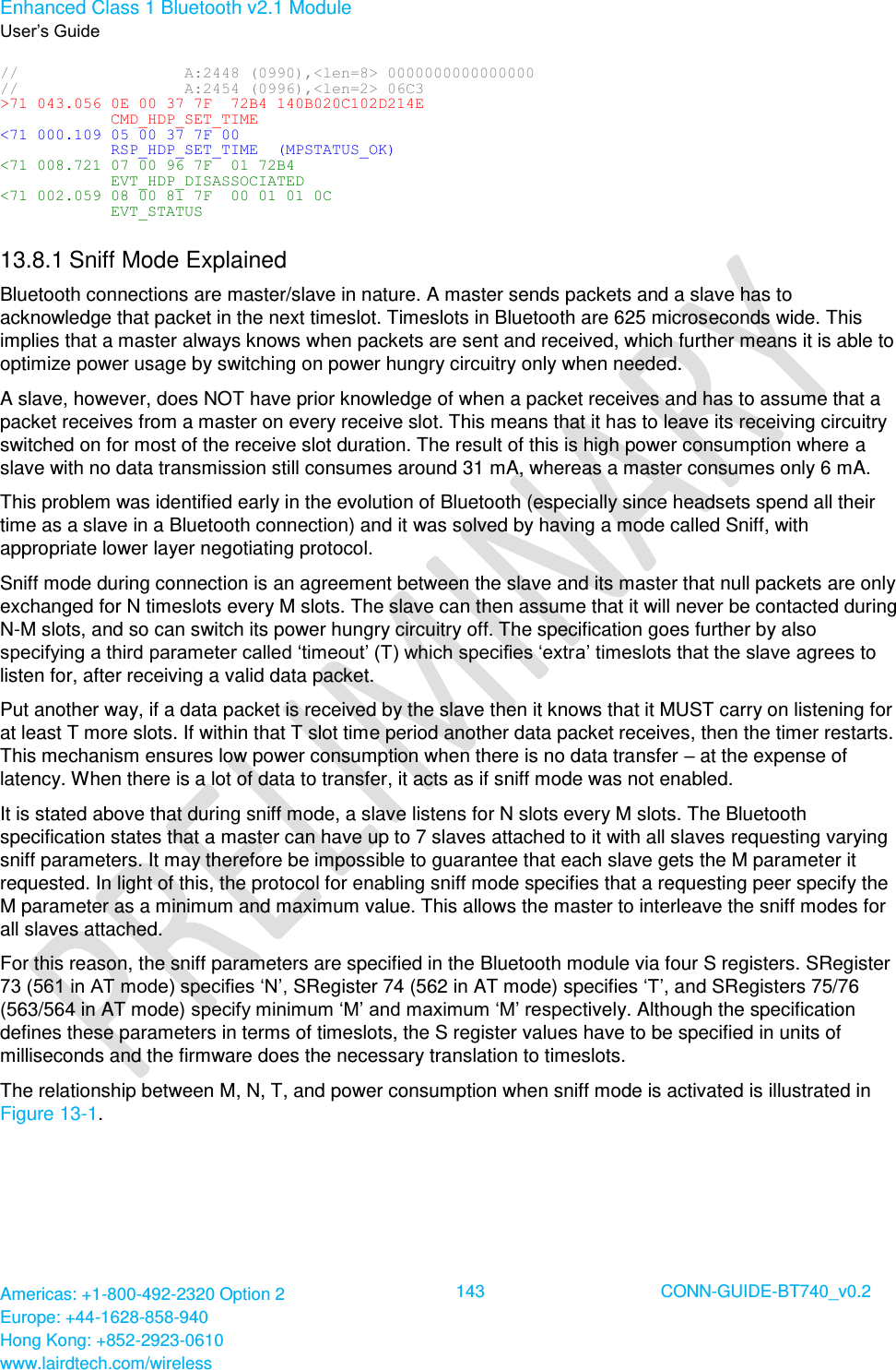
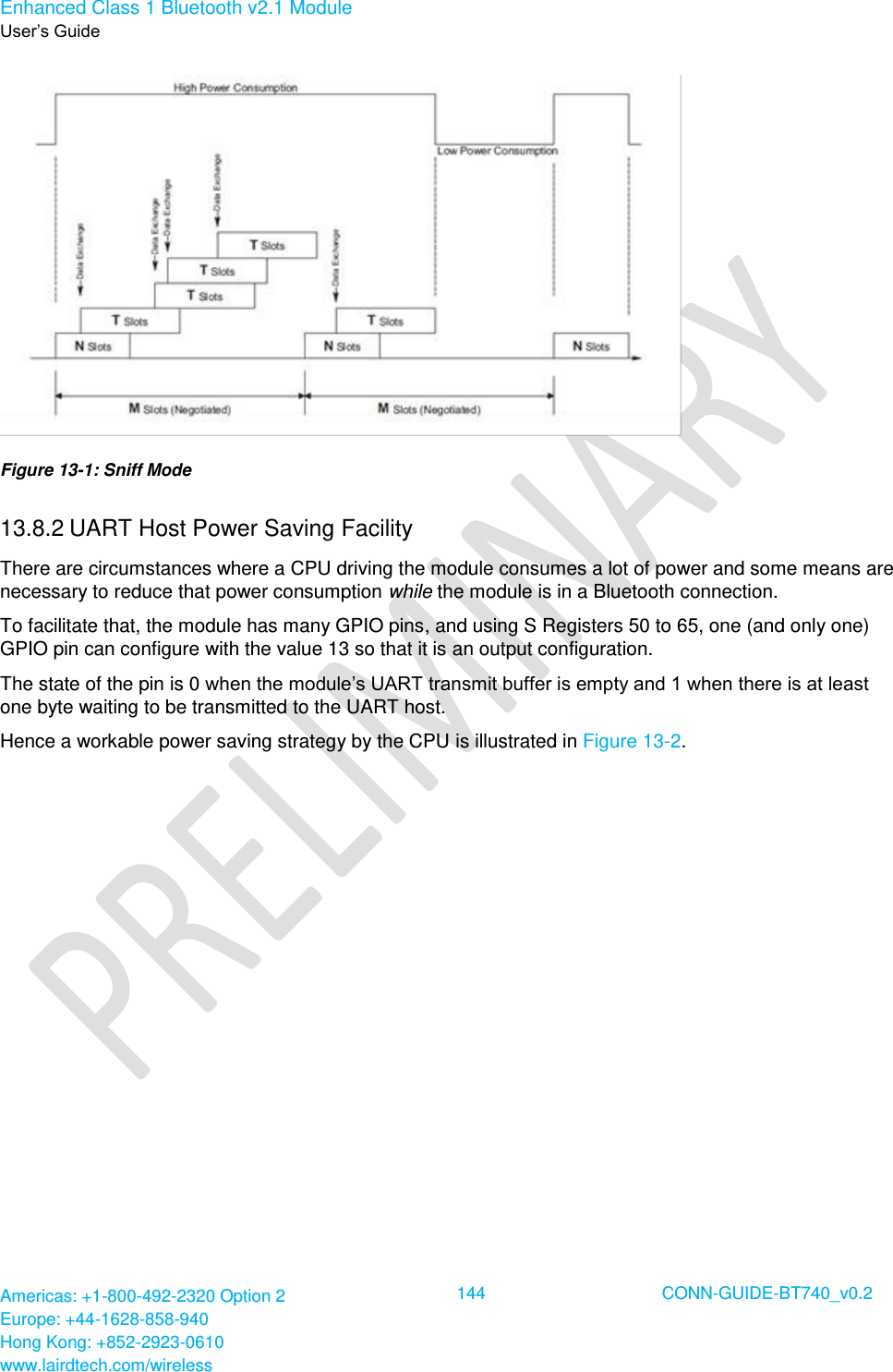
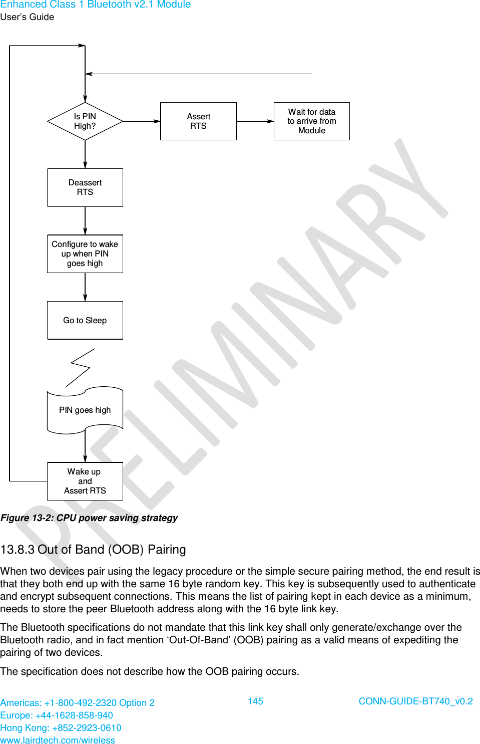
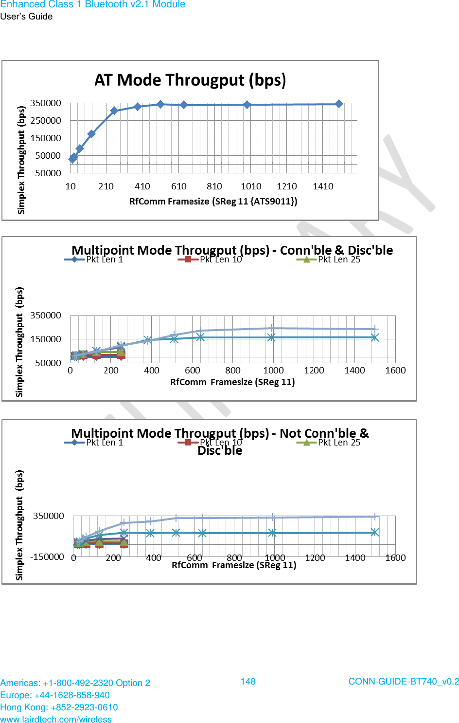
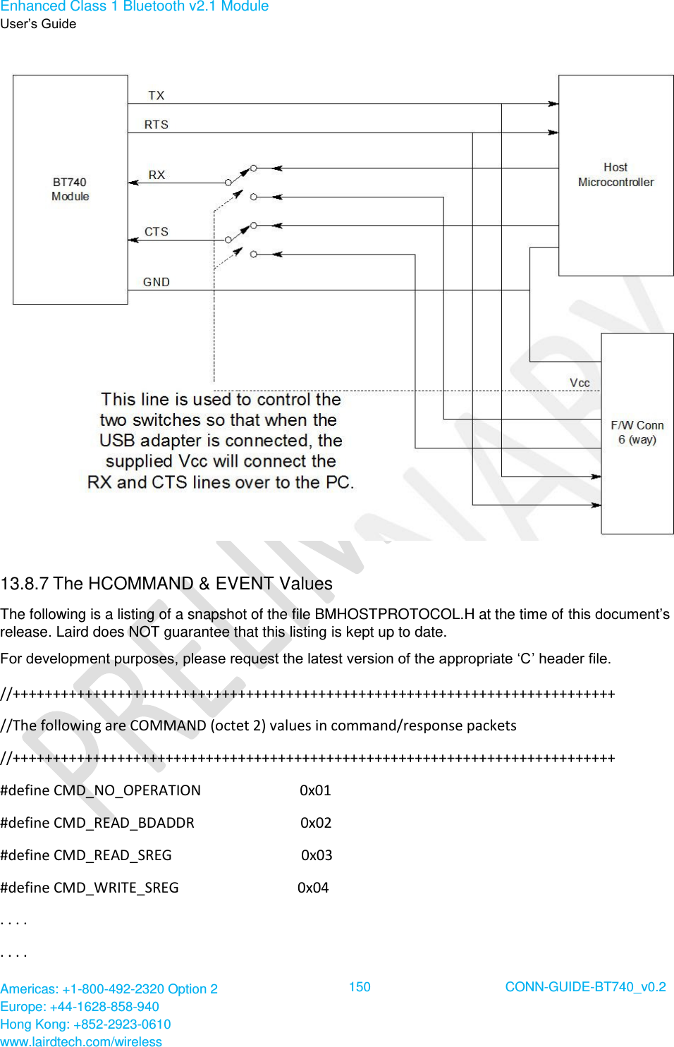
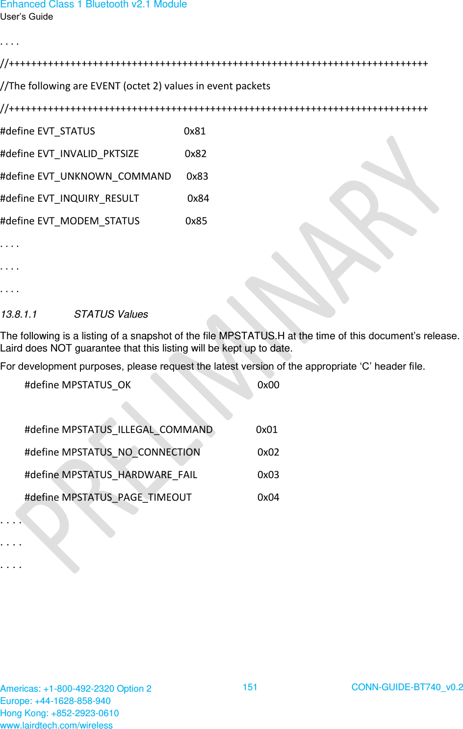

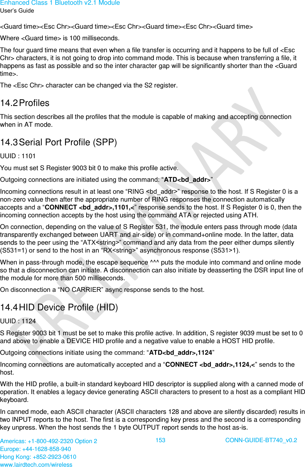
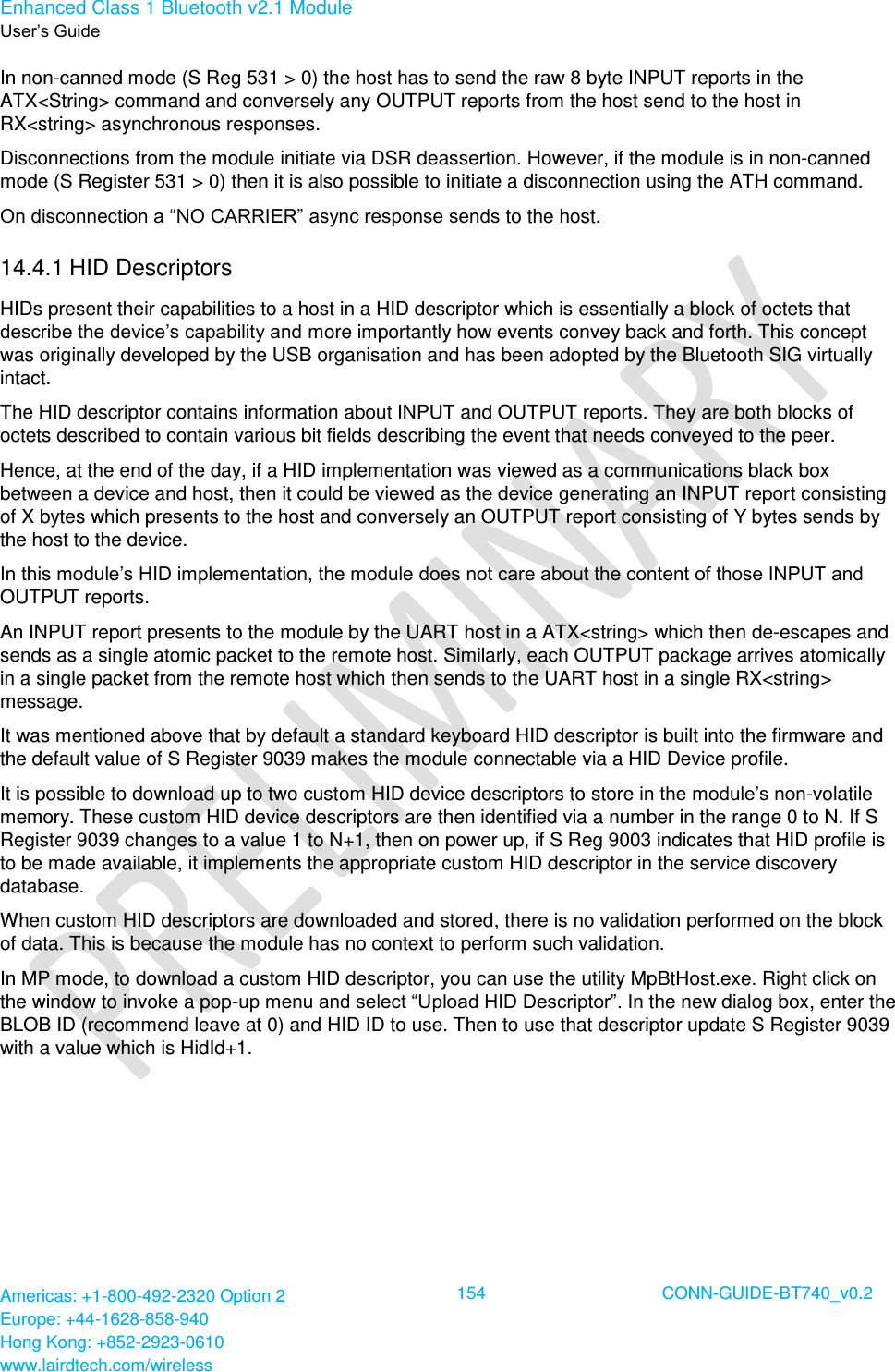

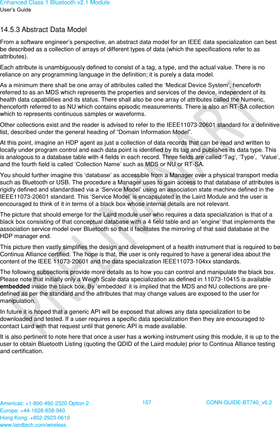
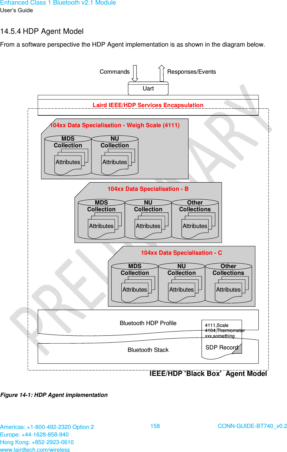
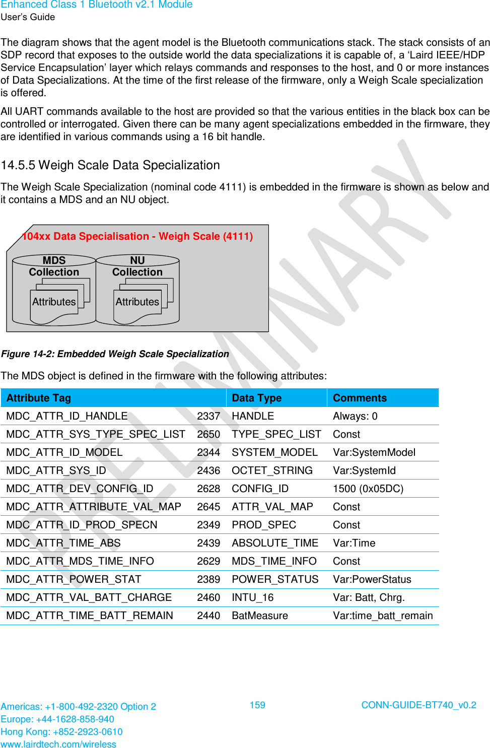
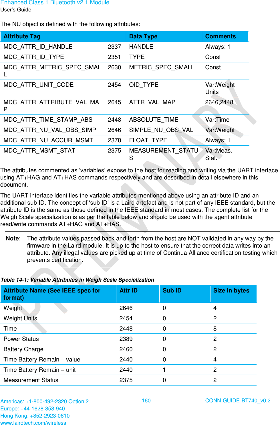
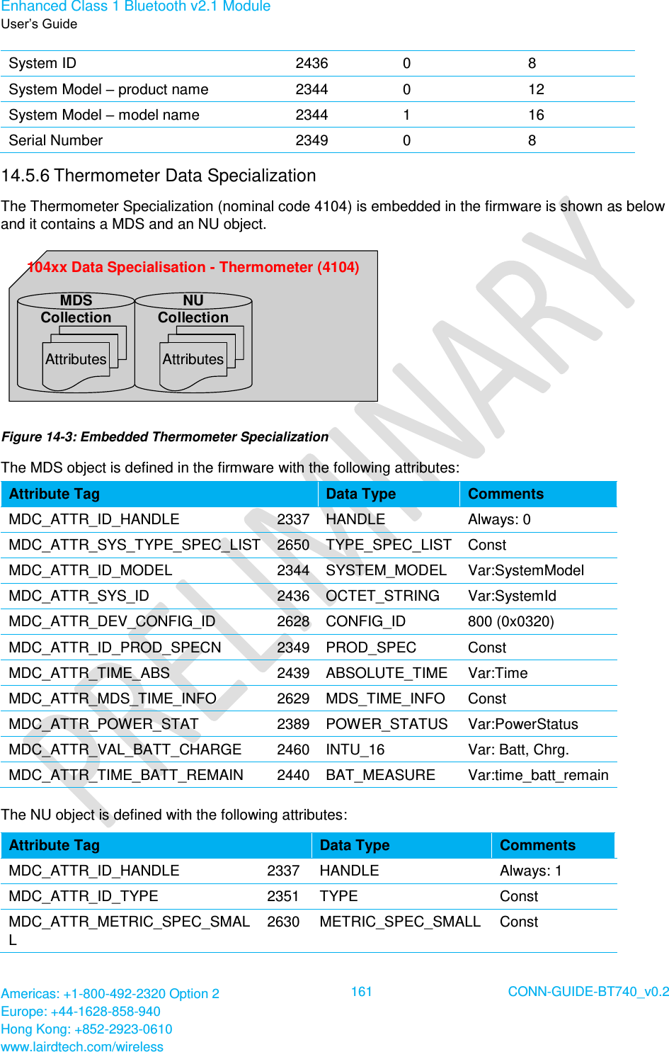
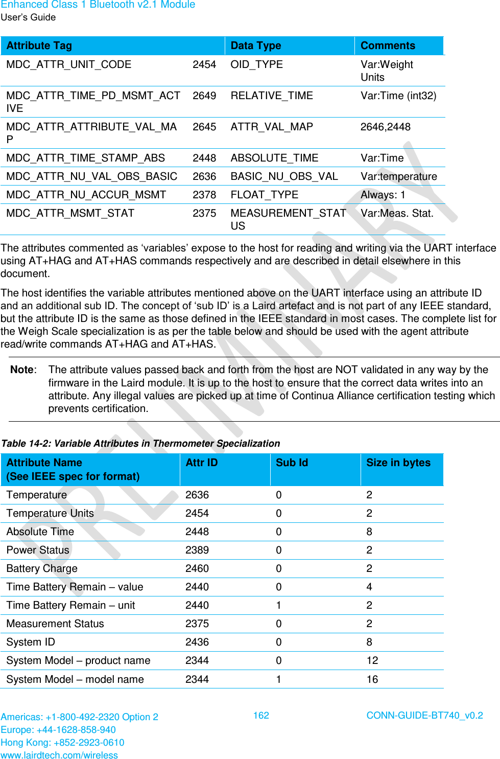
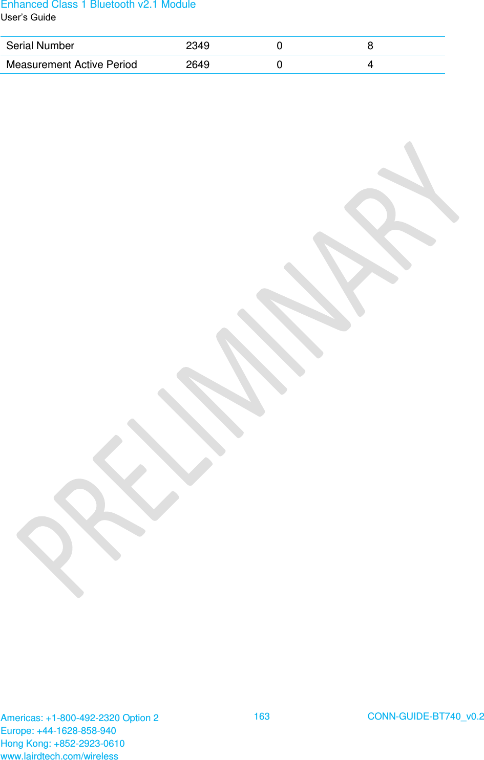
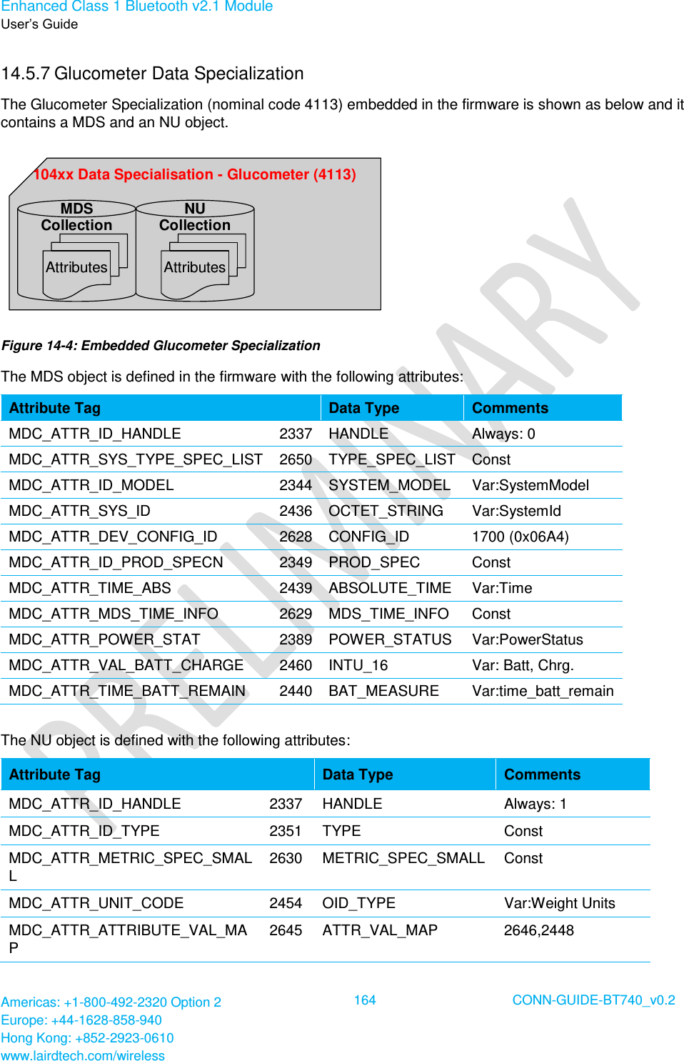
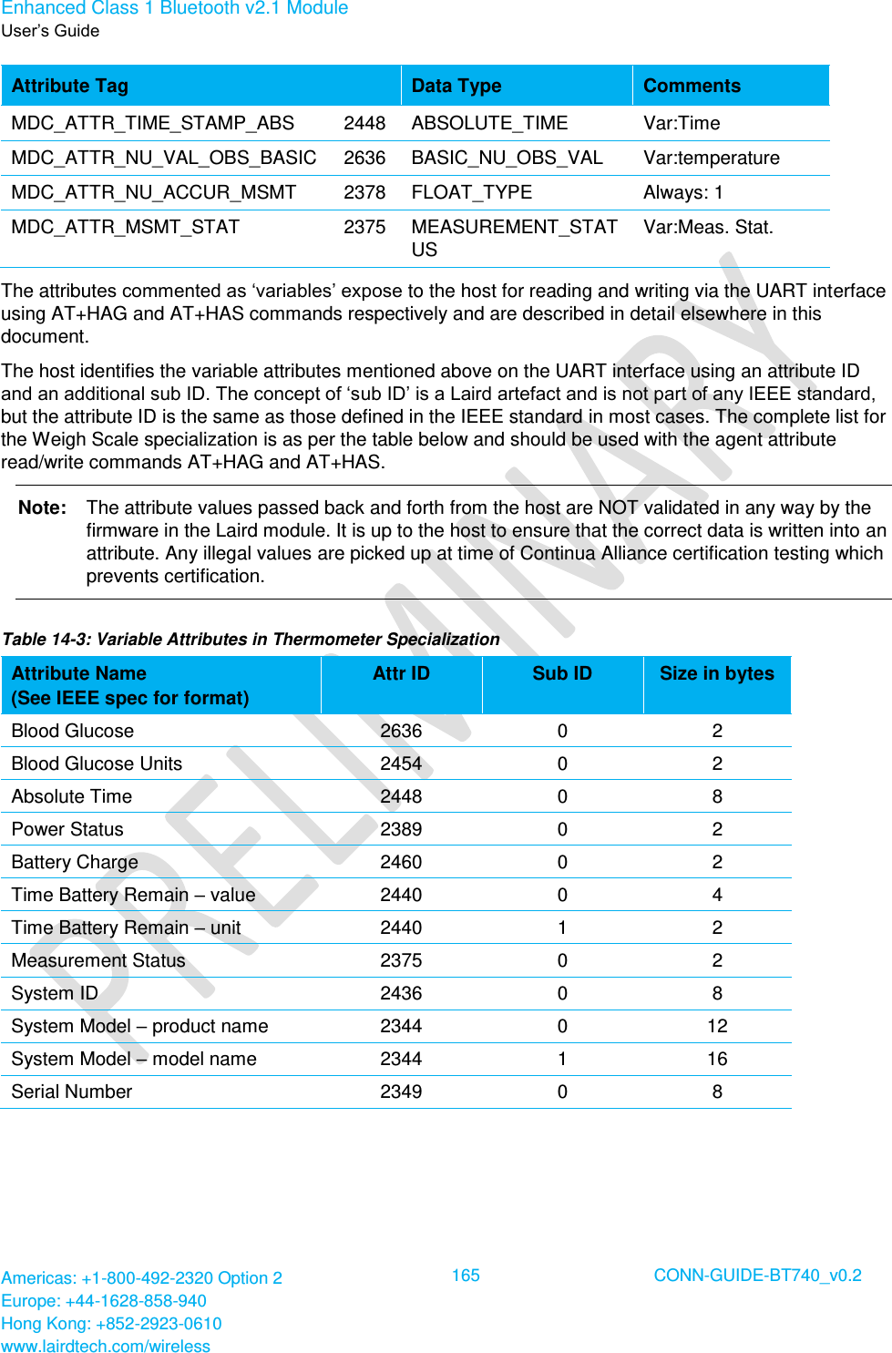
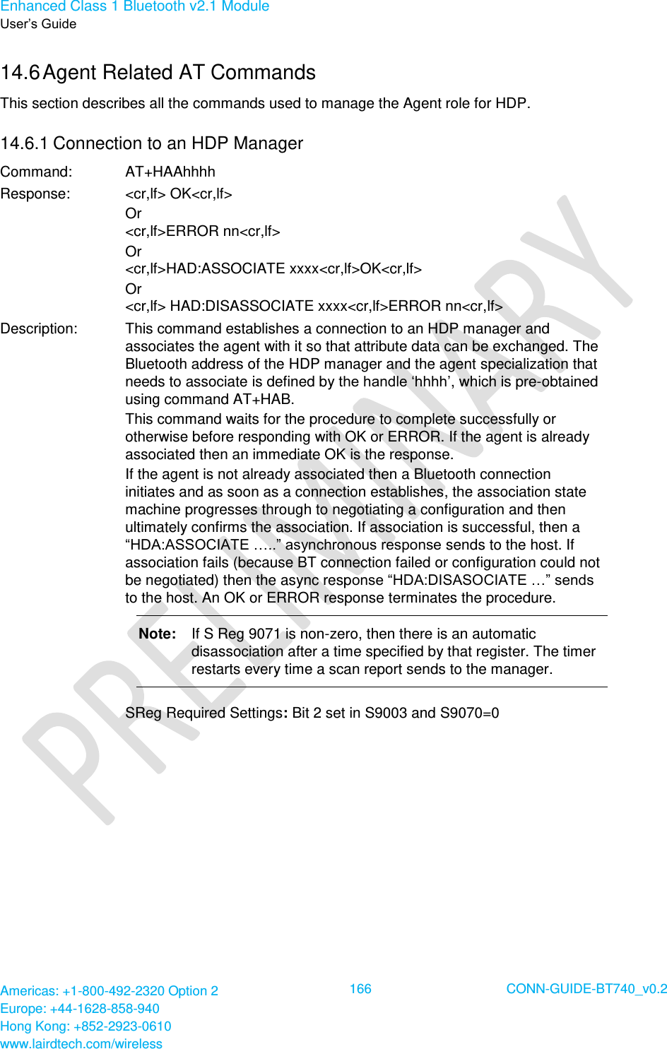
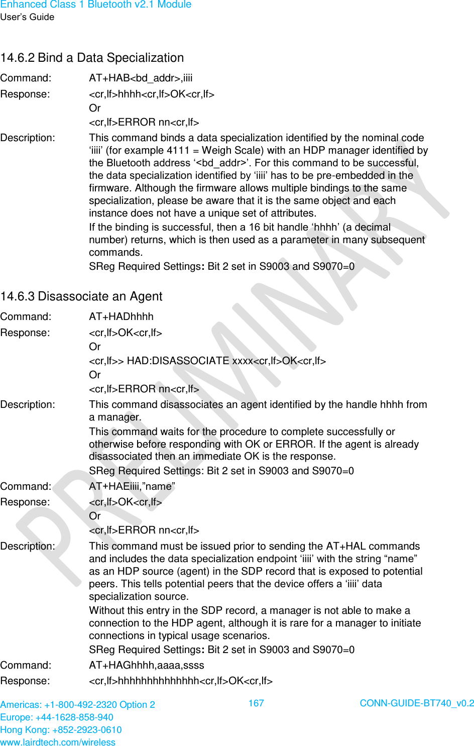
![Enhanced Class 1 Bluetooth v2.1 Module User’s Guide Americas: +1-800-492-2320 Option 2 Europe: +44-1628-858-940 Hong Kong: +852-2923-0610 www.lairdtech.com/wireless 168 CONN-GUIDE-BT740_v0.2 Or <cr,lf>ERROR nn<cr,lf> Description: This command reads (gets) the value of one of the variable attributes identified by ‘aaaa’ and sub ID ‘ssss’ in the attribute collections for that agent identified by the handle ‘hhhh’. For the embedded weigh scale data specialization this command reads the value of an attribute listed in Table 14-1. The value always returns as a string of hexadecimal digits representing the binary value, and the size of that string is even. Different attributes have different sizes. SReg Required Settings: Bit 2 set in S9003 and S9070=0 Command: AT+HAL Response: <cr,lf>OK<cr,lf> Or <cr,lf>ERROR nn<cr,lf> Description: This command must issue after sending at least one AT+HAE command, and registers and activates the SDP record with information supplied in the AT+HAE commands. Without the SDP record, a manager is not able to make a connection to the HDP agent, although it is rare for a manager to initiate connections in typical usage scenarios. SReg Required Settings: Bit 2 set in S9003 and S9070=0 Command: AT+HARhhhh,pppp[,aaaa[,aaaa[…]]] Response: <cr,lf> OK<cr,lf> Or <cr,lf>ERROR nn<cr,lf> Description: This command triggers a scan report for person ID ‘pppp’ (16 bit decimal number) from the agent identified by handle ‘hhhh’. If the agent is not associated with the bound manager (see AT+HAB) then it first triggers the start of an association. Once association exists, a scan report sends. If [,aaaa[,aaaa[…]]] is absent from the command, then the standard scan report as identified by the attribute MDC_ATTR_ATTRIBUTE_VAL_MAP in the NU collection sends to the manager. Otherwise, the [,aaaa[,aaaa[…]]] can be a list of any attribute mentioned in the NU collection. For example, to send a scan report with just the measurement status, just specify the single value 2375. Please note that only attributes mentioned in the NU collection are allowed. Any ‘aaaa’ value not found in the NU collection is silently ignored. SReg Required Settings: Bit 2 set in S9003 and S9070=0 Command: AT+HAShhhh,aaaa,ssss,hhhhhhhhhhhh Response: <cr,lf> OK<cr,lf> Or <cr,lf>ERROR nn<cr,lf> Description: This command writes (sets)a new value ‘hhhhhhhhhhhh’ to one of the variable attributes (identified by ‘aaaa’ and sub ID ‘ssss’) in the attribute](https://usermanual.wiki/Laird-Connectivity/BT700.user-manual-BT740-series/User-Guide-1969496-Page-168.png)
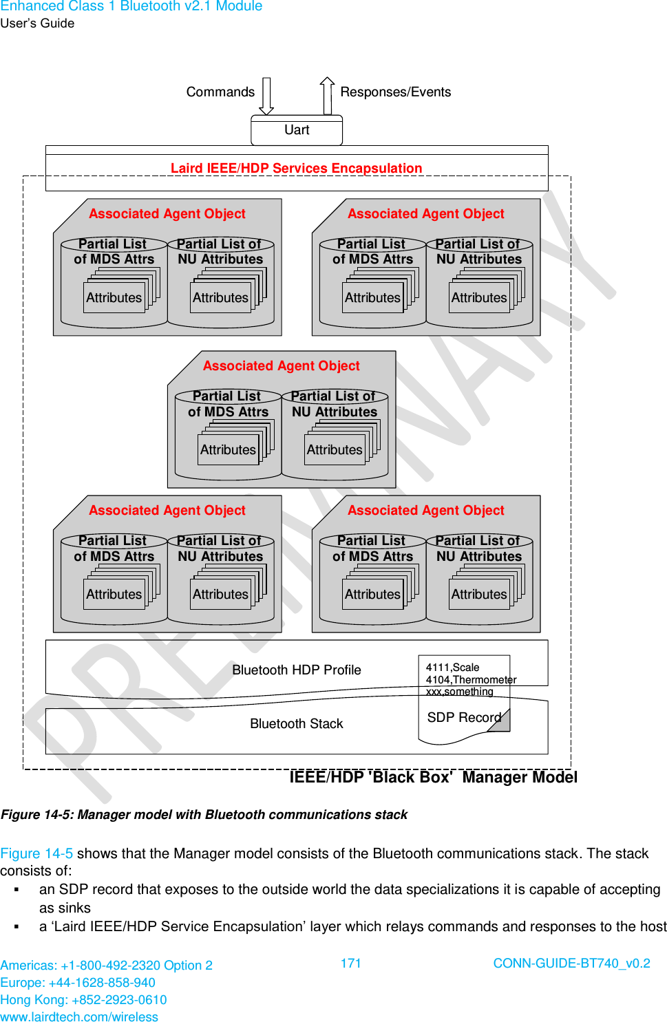
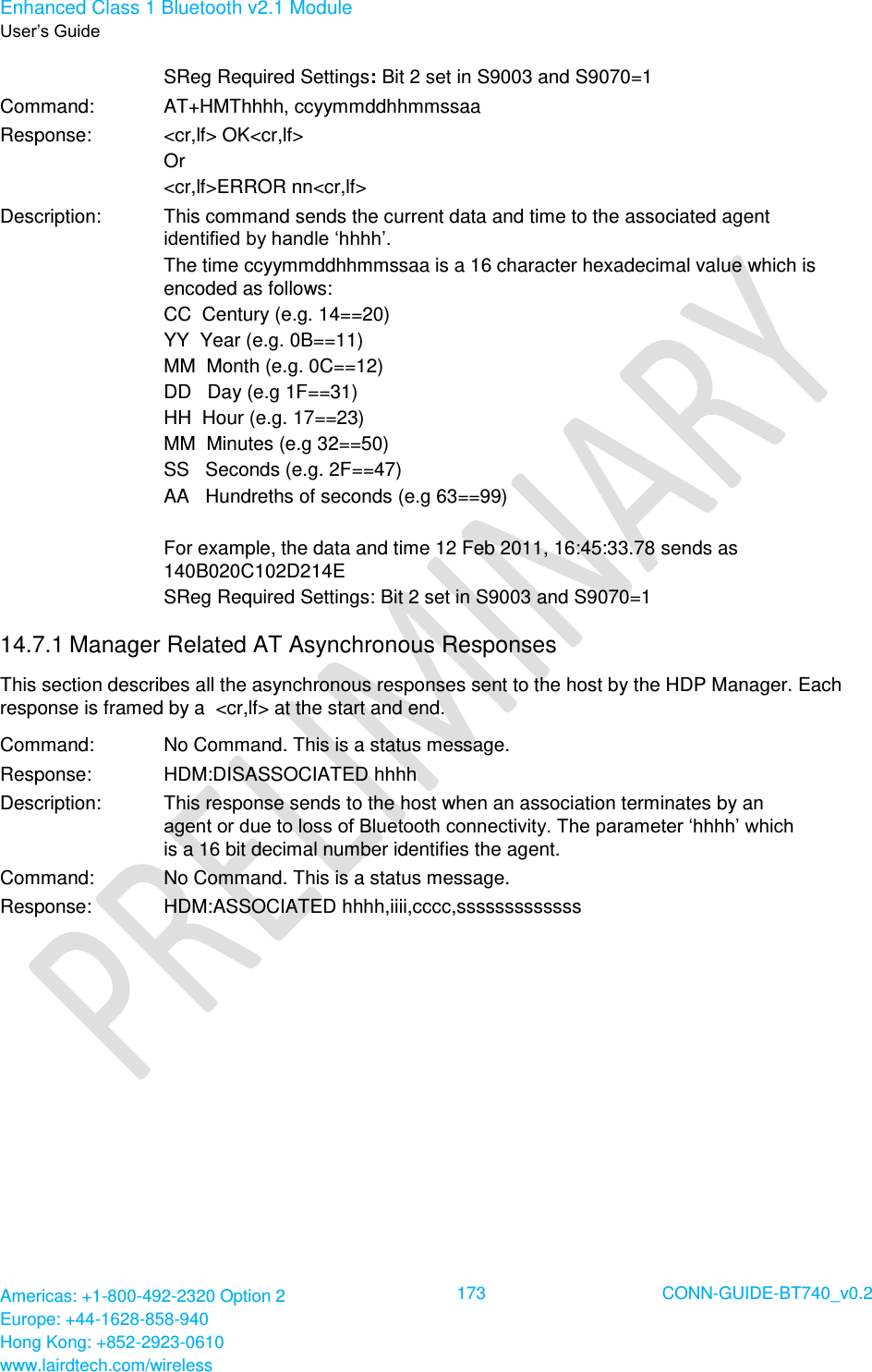
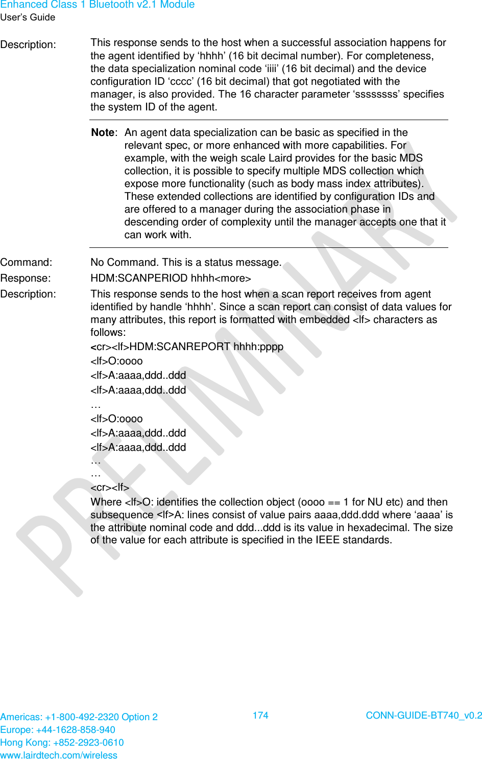
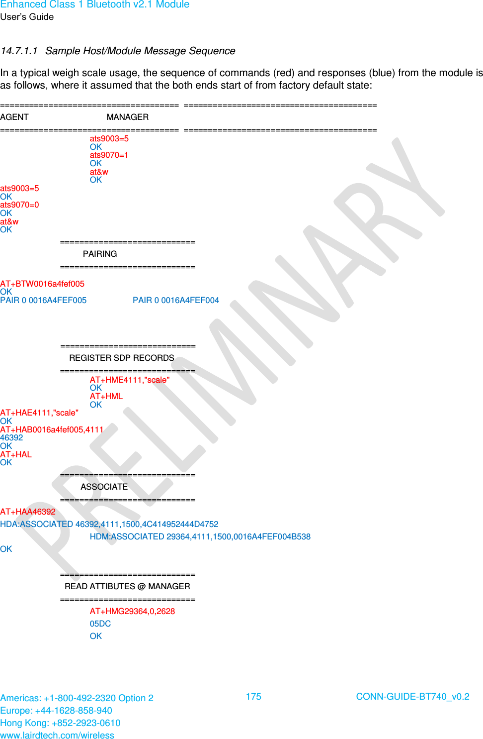
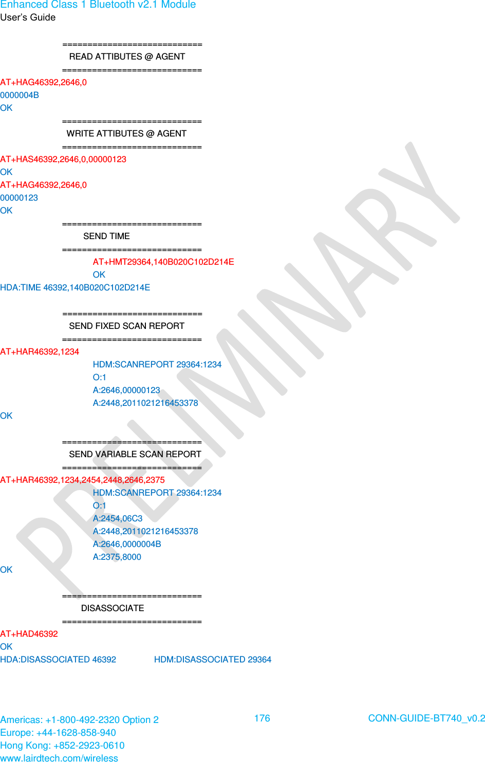
![Enhanced Class 1 Bluetooth v2.1 Module User’s Guide Americas: +1-800-492-2320 Option 2 Europe: +44-1628-858-940 Hong Kong: +852-2923-0610 www.lairdtech.com/wireless 179 CONN-GUIDE-BT740_v0.2 As you can see, the host is able to determine if SSP or legacy pairing is in progress because in the former the challenge message is “PASSKEY?” whereas in the latter it is “PIN ?”. In the ‘just works’ scenario the PAIR 0 message informs the host that a pairing is complete. 14.7.4.4 Host processing of the “PASSKEY? N” response The full format of the PASSKEY? message to the host is: PASSKEY? N <bd_addr>[,passcode] N is 1, 2, or 3 and “,passcode” is not present when N=3. When N=1, this message requires the host to just display the passcode. The module does not expect any confirmation from the host. When N=2, this message requires the host to display the passcode so that the user can accept or reject the pairing. The host sends the AT+BTKY command to accept the pairing, and to reject it sends AT+BTKN. When N=3, the passcode is not provided and the host submits the AT+BTK=”passcode” command. To reject, it can send any value not matching the passcode displayed at the remote end OR send AT+BTK=””. In the case of pairing where the I/O capability is none, the pairing occurs with ‘just works’ procedure where both ends automatically accept the pairing. In this case the module becomes aware that the pairing happened when it receives the “PAIR N <bd_addr>” response. 14.7.4.5 GPIO Access via SReg 619 and 620 The GPIO can be read and written to in AT mode via S registers 619 and 620. SReg 620 reads the current states of all GPIO pins and displays as hex value with a ‘&’ prefix. To write to output pins, a nonzero mask MUST first write to S register 619. Subsequently, any value written to S Reg 620 only affects GPIO pins which have a corresponding bit in S Reg 619 set to 1. 14.7.5 GPIO Exchange via RFCOMM Modem Signalling There is a modem signalling message in an SPP connection that exchanges between peers. It conveys the status of 4 bits called RTR, RTC, DV, and IC, which normally map to DTR/DSR, RTS/CTS, DCD and RI respectively. This on-air message is transparent and happens in the ‘background’ as and when required. The firmware in the module allows GPIO to map to those 4 bits. In total 8 GPIO pins can be mapped: 4 for inputs mapped to the bits that are sent to the peer, and 4 for outputs updated when a modem signalling message arrives from the peer. It is not necessary to map all 8 bits and it is perfectly acceptable to have no pins mapped (which is the default). S Registers 651 to 654 inclusive specify OUTPUT pins which update when a modem signal message arrives from a peer. S Registers 661 to 664 inclusive specify INPUT pins which are monitored for changes of state, and when detected result in a modem signal to be sent to the peer.](https://usermanual.wiki/Laird-Connectivity/BT700.user-manual-BT740-series/User-Guide-1969496-Page-179.png)
![Enhanced Class 1 Bluetooth v2.1 Module User’s Guide Americas: +1-800-492-2320 Option 2 Europe: +44-1628-858-940 Hong Kong: +852-2923-0610 www.lairdtech.com/wireless 181 CONN-GUIDE-BT740_v0.2 14.7.6 Enhanced Inquiry Responses Bluetooth 2.1 specification allows up to 240 bytes of extended inquiry data. On BT740-Sx modules, this data is limited to a maximum length based on firmware builds due to internal memory restrictions. Extended inquiry data transmits e.g. the friendly name, UUIDs of supported profiles, or user defined data within the inquiry process and without a Bluetooth connection. The architecture for managing EIR data is composed of a BLOB buffer, a set of AT commands around them, and: Baseband (EIR data visible to inquiring devices) RAM buffer (allows accumulation of data) EIR persistent store (non-volatile buffer, copied to baseband at boot time) As the input buffer length for one AT command is limited, there is a RAM buffer to accumulate several short data packets. The accumulated data of the RAM buffer can be copied to the baseband where it becomes visible to other inquiring devices immediately. The content of the RAM buffer can copy to the EIR persistent store. If the EIR persistent store contains data, it copies to the baseband automatically at boot time. This allows a flexible usage of extended inquiry data. For example, data with a low data rate (e.g. temperature) can transmit without creating a connection between Bluetooth devices, however without the benefits of encryption and authentication. The command AT+BTB is provided to manage EIR data in AT mode. 14.7.6.1 EIR Data Format When passing EIR data (“<data>”) to AT commands (AT+BTB=”<data>” / AT+BTB+”<data>”), each byte should be presented by its ASCII representation whenever it is a printable character. Each non-printable ASCII character must be presented as 2 hex digits with a preceding ‘\’. For example, a byte of decimal value 5 is presented as “\05” because the ASCII character of 05d is not printable. A decimal value of 43 should be presented as ‘+’ because ‘+’ is the ASCII character representing 43d. The module also accepts “\2B” (the hexadecimal presentation of 43d) but at the price of two redundant characters. Exceptions: ‘“’ (quotation mark) must be presented as \22 ‘\’ (backslash) must be presented as \5C When querying the content of the BLOB, non-printable ASCII characters are presented by 2 hex digits with preceding ‘\’. Exceptions: ‘“’ (quotation mark) is presented as \22 ‘\’ (backslash) is presented as \5C ‘,’ (comma) is presented as \2C Any data passed to the baseband must match the format defined in the Bluetooth Specification Version 2.1 + EDR [1], vol3, Part C – Generic Access Profile, 8 Extended Inquiry Response Data Format (page 1305 in the *.pdf file). The AT command interpreter does not perform any checks on the baseband data format.](https://usermanual.wiki/Laird-Connectivity/BT700.user-manual-BT740-series/User-Guide-1969496-Page-181.png)
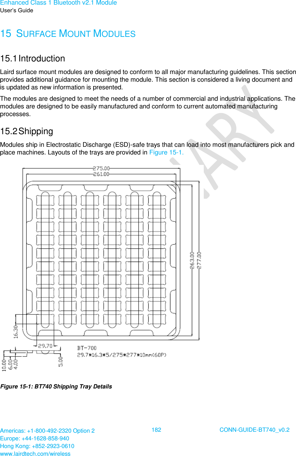
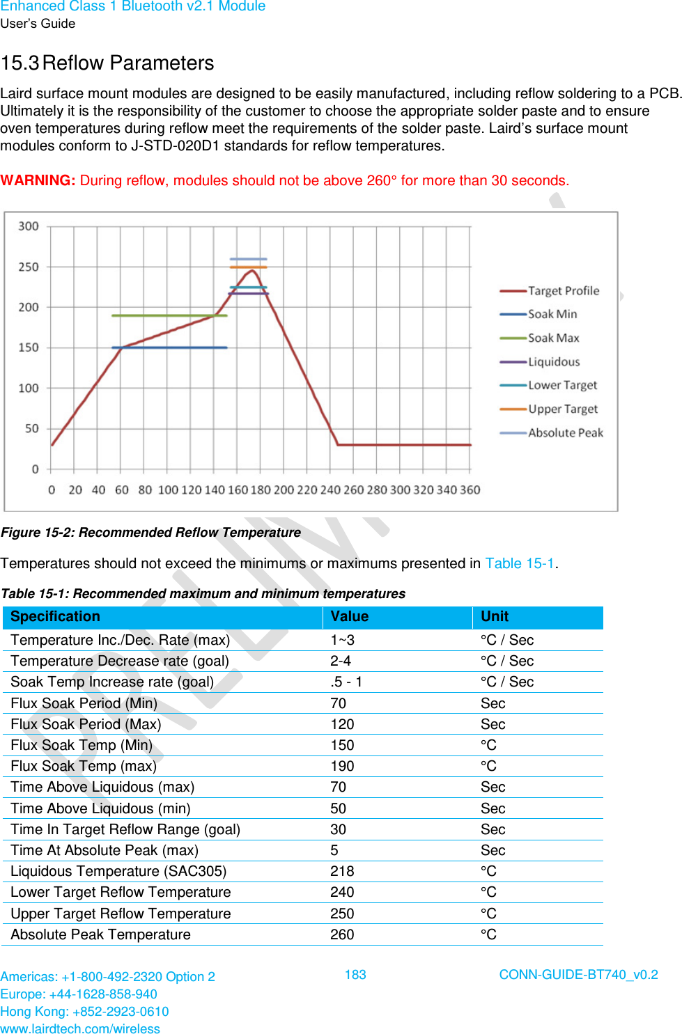
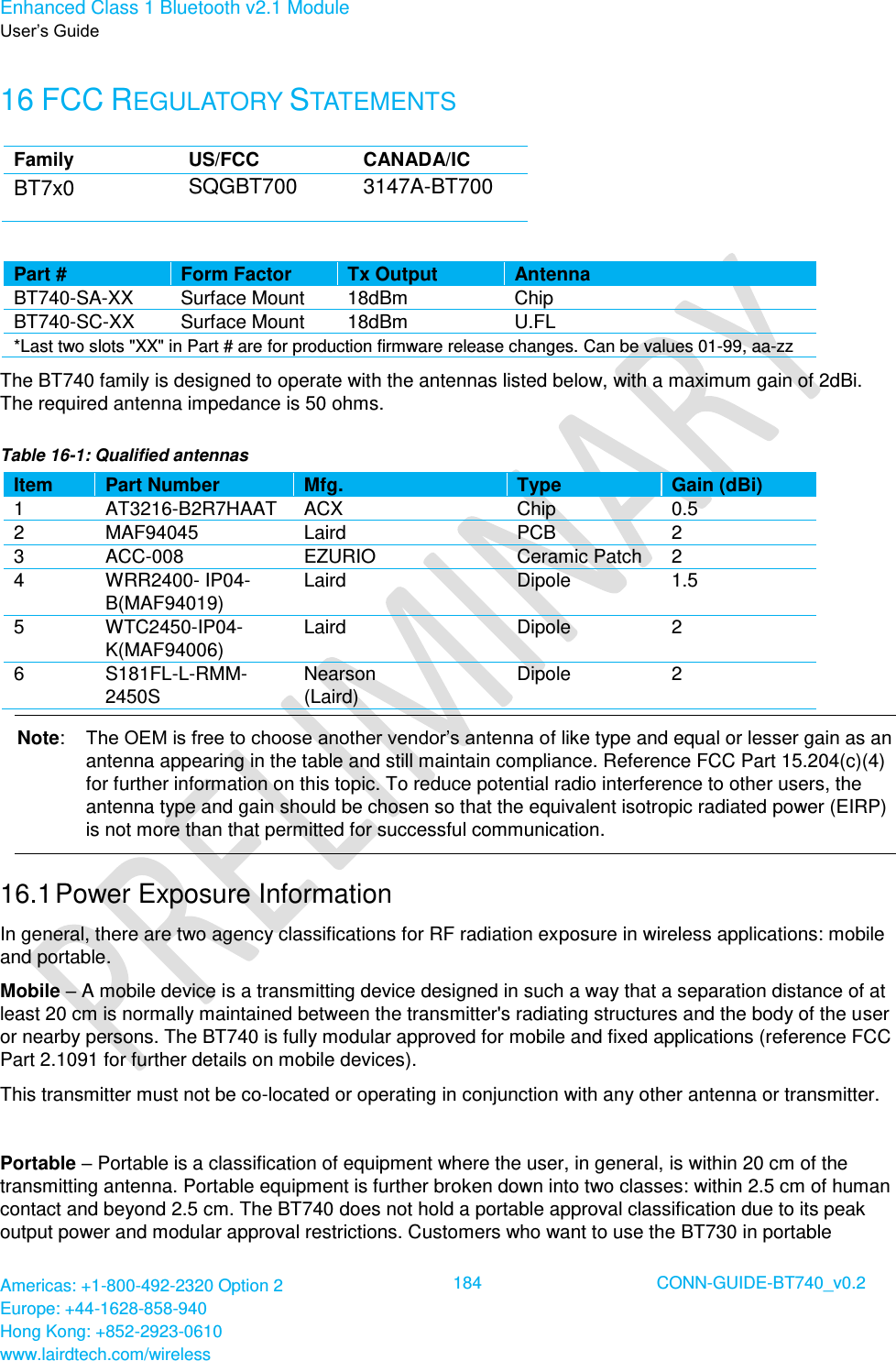
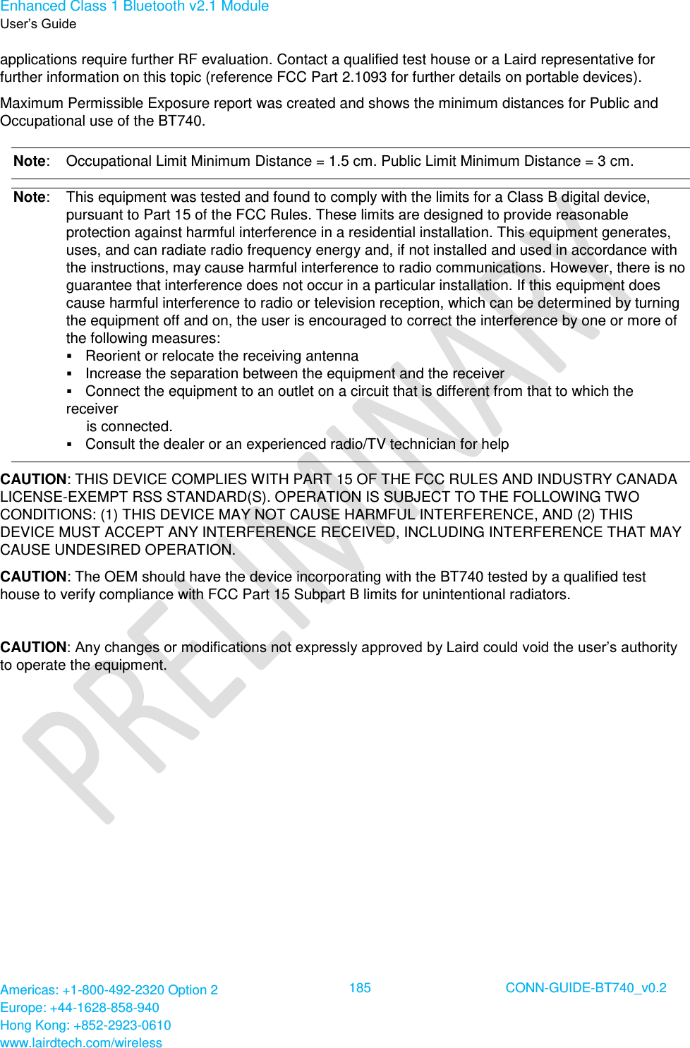
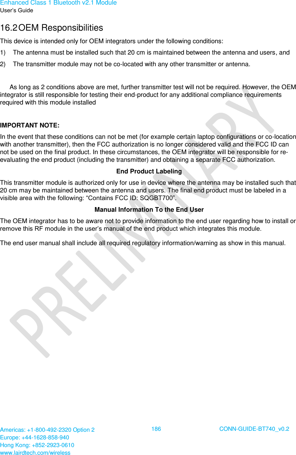
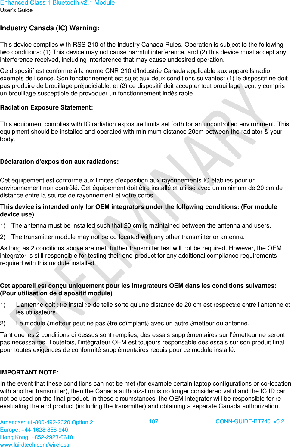
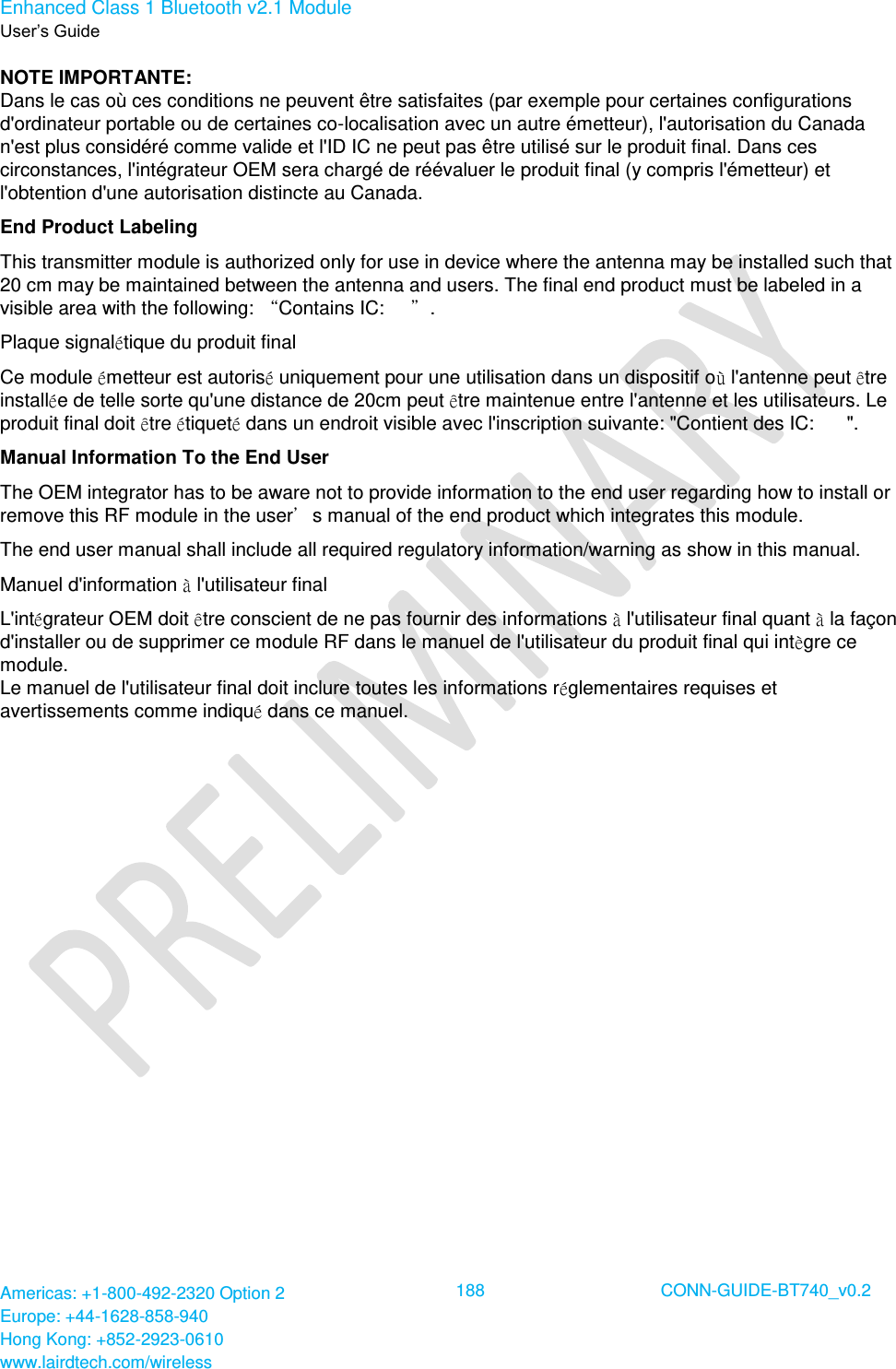
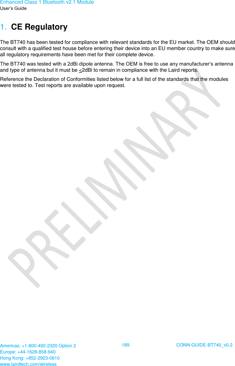
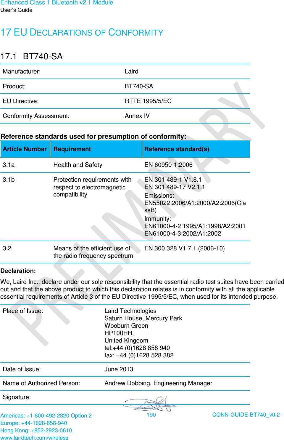
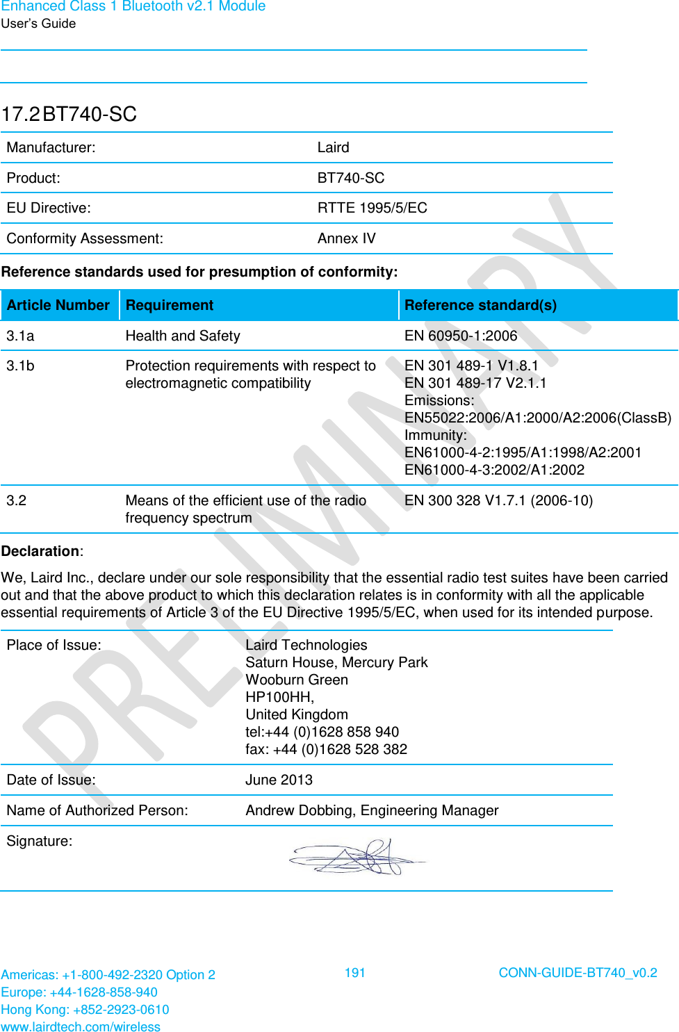
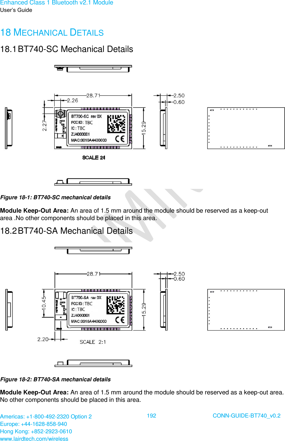
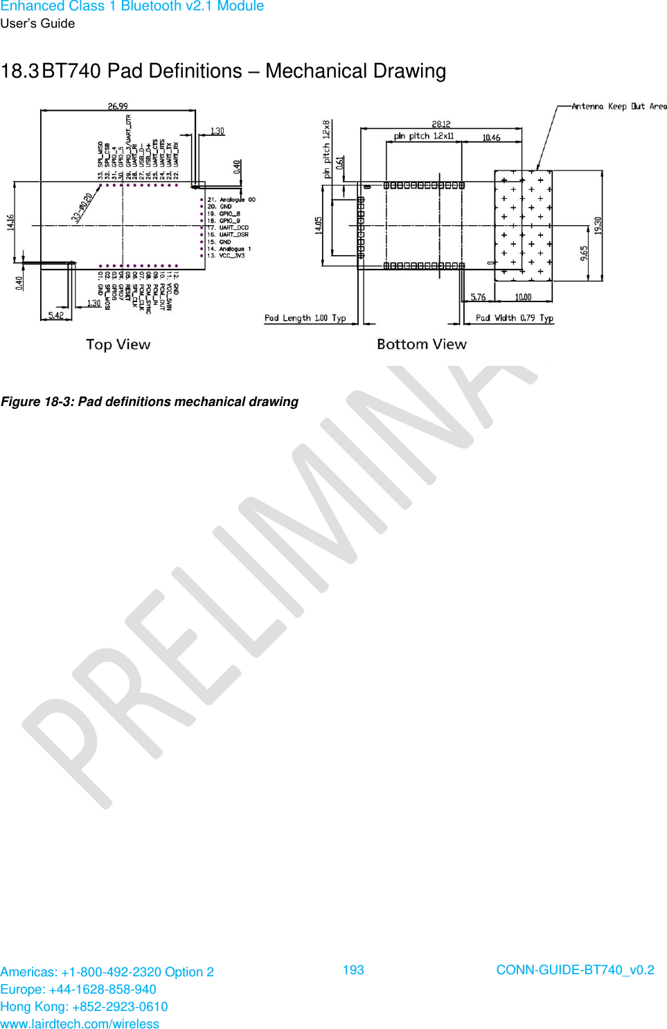
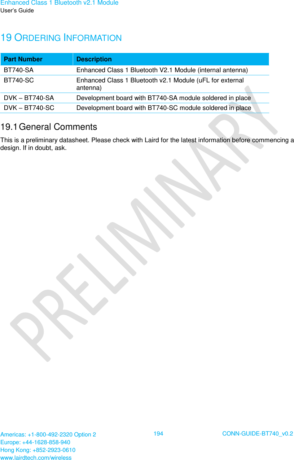
![Enhanced Class 1 Bluetooth v2.1 Module User’s Guide Americas: +1-800-492-2320 Option 2 Europe: +44-1628-858-940 Hong Kong: +852-2923-0610 www.lairdtech.com/wireless 199 CONN-GUIDE-BT740_v0.2 Index ^^^ ........................................................................ 17 ‘AT’ S Registers ................................................. 46 Abstract Data Model ........................................... 146 Agent Related AT Asynchronous Responses .... 157 Agent Related AT Commands............................ 154 Agent UART Traffic for Chart ............................. 131 Associate with Manager ..................................... 100 Associated ......................................................... 118 AT.. ...................................................................... 17 AT Commands and Responses ........................... 16 AT&F* .................................................................. 21 AT&F*AT* ............................................................ 22 AT&F*MP* ............................................................ 22 AT&F+ .................................................................. 21 AT+BTB+<string> ................................................ 23 AT+BTB=<string> ................................................ 22 AT+BTBnnnn ....................................................... 23 AT+BTD* .............................................................. 24 AT+BTD<bd_addr> .............................................. 24 AT+BTF<bd_addr> .............................................. 24 AT+BTG ............................................................... 24 AT+BTI ................................................................. 25 AT+BTIE .............................................................. 25 AT+BTIN .............................................................. 25 AT+BTIV .............................................................. 25 AT+BTK=<string> ................................................ 25 AT+BTKN ............................................................. 26 AT+BTKY ............................................................. 26 AT+BTN? ............................................................. 26 AT+BTN=<string> ................................................ 26 AT+BTP ............................................................... 27 AT+BTQ ............................................................... 27 AT+BTT? .............................................................. 27 AT+BTT<bd_addr> .............................................. 28 AT+BTTn? ............................................................ 28 AT+BTW<bd_addr> ............................................. 28 AT+BTX ............................................................... 29 AT+HAAhhhh ............................................... 29, 154 AT+HAB<bd_addr>,iiii.................................. 29, 155 AT+HADhhhh ............................................... 29, 155 AT+HAE,iiii,”endpointname” ................................. 30 AT+HAEiiii,”name” ............................................. 155 AT+HAGhhhh,aaaa,ssss.............................. 30, 155 AT+HAL ....................................................... 30, 156 AT+HARhhhh,pppp[,aaaa[,aaaa[…]]] .................. 30 AT+HAShhhh,aaaa,ssss,ddddd ........................... 31 AT+HAShhhh,aaaa,ssss,hhhhhhhhhhhh ........... 156 AT+HME,iiii,”endpointname” ................................ 31 AT+HMEiiii,”name” ............................................. 160 AT+HMGhhhh,oooo,aaaa ............................ 32, 160 AT+HML ....................................................... 31, 160 AT+HMThhhh, ccyymmddhhmmssaa ................ 161 AT+HMThhhh,ttttttt ............................................... 32 AT+KY<addr>,<link_key> .................................... 32](https://usermanual.wiki/Laird-Connectivity/BT700.user-manual-BT740-series/User-Guide-1969496-Page-199.png)