Laird Connectivity BT700 Class 1 Bluetooth Data Module User Manual BT740 series
Laird Technologies Class 1 Bluetooth Data Module BT740 series
Contents
- 1. user manual (BT730 series)
- 2. user manual (BT740 series)
user manual (BT740 series)


Enhanced Class 1 Bluetooth v2.1 Module
User’s Guide
Americas: +1-800-492-2320 Option 2
Europe: +44-1628-858-940
Hong Kong: +852-2923-0610
www.lairdtech.com/wireless
2
CONN-GUIDE-BT740_v0.2
REVISION HISTORY
Revision
Revision Date
Description
Version
0.1
12/0413
Initial release to CA
Version -.2
01/05/13
JK updates and DW regulatory

Enhanced Class 1 Bluetooth v2.1 Module
User’s Guide
Americas: +1-800-492-2320 Option 2
Europe: +44-1628-858-940
Hong Kong: +852-2923-0610
www.lairdtech.com/wireless
3
CONN-GUIDE-BT740_v0.2
Table of Contents
1 Overview and Key Features .................................................................................................. 4
2 Specifications ....................................................................................................................... 5
3 I/O Characteristics .............................................................................................................. 11
4 Functional Description ........................................................................................................ 12
5 AT Command Set ............................................................................................................... 15
6 S Registers ......................................................................................................................... 35
7 Error Codes ........................................................................................................................ 50
8 Multipoint Protocol .............................................................................................................. 53
9 Module Events .................................................................................................................. 118
10 HDP Profile Related Events .............................................................................................. 127
11 Debug Events ................................................................................................................... 128
12 Data Channels .................................................................................................................. 129
13 Multipoint Application Examples ....................................................................................... 134
14 AT Application Examples .................................................................................................. 152
15 Surface Mount Modules .................................................................................................... 182
16 FCC Regulatory Statements ............................................................................................. 184
17 EU Declarations of Conformity .......................................................................................... 190
18 Mechanical Details ............................................................................................................ 192
19 Ordering Information ......................................................................................................... 194
20 Bluetooth SIG Approvals ................................................................................................... 195
21 Glossary of Terms ............................................................................................................ 197

Enhanced Class 1 Bluetooth v2.1 Module
User’s Guide
Americas: +1-800-492-2320 Option 2
Europe: +44-1628-858-940
Hong Kong: +852-2923-0610
www.lairdtech.com/wireless
4
CONN-GUIDE-BT740_v0.2
1 OVERVIEW AND KEY FEATURES
Every BT740 series Bluetooth® module from Laird is designed to add robust, long-range Bluetooth data
connectivity to any device. Based on the market-leading Cambridge Silicon Radio (CSR) BC04 chipset,
BT740 modules provide exceptionally low power consumption with outstanding Class 1 range via 18 dBm
of transmit power. The modules support the latest Bluetooth Version 2.1 specification, including Secure
Simple Pairing (SSP), which improves security and enhances the ease of use for end customers. A broad
range of Bluetooth profiles such as Serial Port Profile (SPP) and other vital features make BT740
modules superior to other Bluetooth modules.
With a compact footprint of 15.29 x 28.71 mm, the modules deliver maximum range with a minimum size.
To ease integration, the modules are designed to support a separate power supply for I/O. Another
integration advantage is the inclusion of a complete Bluetooth protocol stack with support for multi-point
connections and numerous Bluetooth profiles, including SPP, Human Interface Device (HID) profile, and
Health Device Profile (HDP). BT740 modules fully qualify as a Bluetooth End Products, enabling
designers to integrate the modules in devices without the need for further Bluetooth qualification.
An integrated AT command processor interfaces to the host system over a serial port using an extensive
range of AT commands. The AT command set abstracts the Bluetooth protocol from the host application,
saving many months of programming and integration time. It provides extremely short integration times
for data-oriented Bluetooth applications.
Included firmware provides programming support for multi-point applications that use up to seven
simultaneous data connections to and from the robust BT740 module. A low-cost developer’s kit makes it
easy for an OEM to integrate the module and guarantees the fastest route to prototype and then mass
production.
Features & Benefits
Application Areas
Bluetooth v2.1 + EDR
External or internal antennas
Comprehensive AT interface for simple
programming
Alternate packet based interface for
complex programming and up to seven
simultaneous connections
Bluetooth EPL
Compact footprint
Class 1 output – 18 dBm
UART interface with GPIO, PCM, and ADC
lines
Industrial temperature range
Field proven firmware used on BTM44x
series of modules
Medical devices
ePOS terminals
Automotive diagnostic equipment
Barcode scanners
Industrial cable replacement
Bluetooth® Profiles Supported
Serial Port Profile (SPP)
Human Interface Device (HID) profile host
and device supported
Health Device Profile (HDP): Agent
supported
IEEE Device Specialization
11073-10415 (Weight Scale)
IEEE Device Specialization
11073 - 10408 (Thermometer)
IEEE Device Specialization
11073 – 10417 (Glucose)

Enhanced Class 1 Bluetooth v2.1 Module
User’s Guide
Americas: +1-800-492-2320 Option 2
Europe: +44-1628-858-940
Hong Kong: +852-2923-0610
www.lairdtech.com/wireless
5
CONN-GUIDE-BT740_v0.2
2 SPECIFICATIONS
2.1 Detailed Specifications
Table 2-1: Detailed specifications
Categories
Feature
Implementation
Wireless
Specification
Bluetooth®
V2.1 + EDR
Frequency
2.402 - 2.480 GHz
Max Transmit Power
Class 1
18 dBm from integrated antenna
18 dBm at UFL antenna connector
Receive Sensitivity
Better than -87 dBm (at 25° C)
Range
>1000m
Data Rates
Up to 2.1 Mbps (over the air)
UART Data Transfer Rate
Circa 350 kbps
Host Interface
UART
TX, RX, DCD, RI, DTR, DSR, CTS, RTS1
Default 9600, n, 8, 1
From 1,200 to 921,600 bps
GPIO
8 configurable lines
ADC
2 lines, 8 bit resolution
PCM
4 lines – see Audio section
Profiles
SPP
Serial Port Profile
HID
Human Interface Device
HDP
Health Device Profile
Command
Interfaces
Operation Modes
AT Command Set
Multi-Point API – seven simultaneous
connections
Firmware Upgrade
Firmware Upgrade over UART
Audio
Support
SCO Channels
PCM Interface
3 x PCM Channels @ 64 kpbs
SCO and eSCO
Configurable as master or slave
8 bit A-law
8 bit µ-law
13 bit linear
PCM Clock available when in slave mode
Supply Voltage
Supply
3.0 – 5.0 V
On-board regulators and brown-out detection
Power Consumption
Various Modes –
Typical values
Idle Mode – TBC
Discoverable –TBC
Inquiry Mode – TBC
Connecting Mode – TBC
Connected Mode (No Data Transfer) – TBC
Connected Mode (Max Data Transfer) – TBC
Sniff Mode – TBC
Enhanced Class 1 Bluetooth v2.1 Module
User’s Guide
Americas: +1-800-492-2320 Option 2
Europe: +44-1628-858-940
Hong Kong: +852-2923-0610
www.lairdtech.com/wireless
6
CONN-GUIDE-BT740_v0.2
Categories
Feature
Implementation
Antenna Options
Internal
Multilayer ceramic - BT740-SA-xx
External
Connection via u.FL - BT740-SC-xx
Physical
Dimensions
15.29 mm x 28.71 mm x 2.5 mm
Weight
1.5 g
Environmental
Operating
-40°C to +85°C
Storage
-40°C to +85°C
Miscellaneous
Lead Free
Lead-free and RoHS compliant
Warranty
1 Year
Development Tools
Development Kit
Development kit DVK-BT740 and software tools
Approvals
Bluetooth®
End Product Listing (EPL)
FCC / IC / CE
All BT740 Series (to be completed)
1. DSR, DTR, RI and DCD are configurable either as GPIO or as modem control lines.
2.2 Hardware Specifications
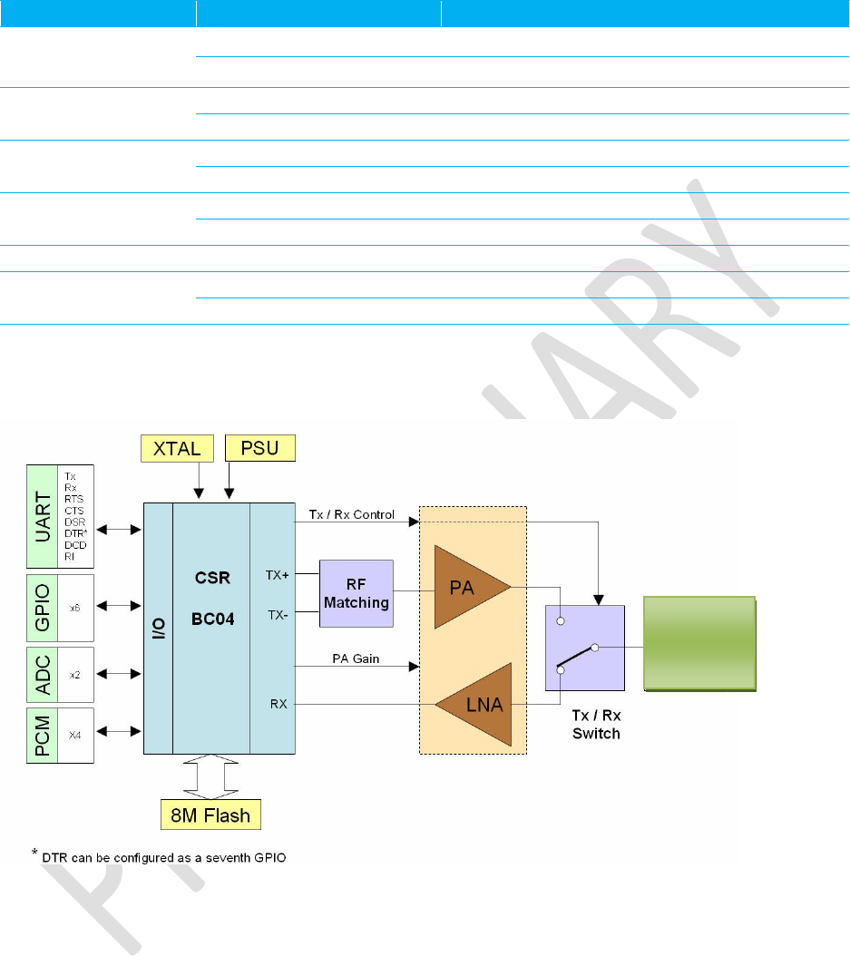
Figure 2-1: Functional Block Diagram
Ceramic Chip
Antenna

Enhanced Class 1 Bluetooth v2.1 Module
User’s Guide
Americas: +1-800-492-2320 Option 2
Europe: +44-1628-858-940
Hong Kong: +852-2923-0610
www.lairdtech.com/wireless
7
CONN-GUIDE-BT740_v0.2
2.3 Pin Definitions
Table 2-2: Pin definitions
Pin
Signal
Description
Comment
1
GND
2
SPI_MOSI
SPI bus serial I/P
See Note 0
3
GPIO6
I/O for host
4
GPIO7
I/O for host
5
RESET
Module reset I/P
See Note 0
6
SPI_CLK
SPI bus clock I/P
See Note 0
7
PCM_CLK
PCM clock I/P
8
PCM_SYNC
PCM sync I/P
9
PCM_IN
PCM data I/P
10
PCM_OUT
PCM Data O/P
11
VCC_5VIN
3.0 V < VIN < 5.0 V
12
GND
13
VCC_3V3
3.3 V Monitor
See Note 0
14
Analogue 1
1.8 V max
15
GND
16
UART_DSR
UART_DSR I/P
17
UART_DCD
UART_DCD I/P or O/ P
18
GPIO_9
I/O for host
19
GPIO_8
I/O for host
20
GND
21
Analogue 00
1.8 V max
22
UART_RX
Receive data I/P
23
UART_TX
Transmit data O/P
24
UART_RTS
Request to Send O/P
25
UART_CTS
Clear to Send I/P
26
USB_D+
Not used for AT module variants
27
USB_D-
Not used for AT module variants
28
UART_RI
Ring Input or Output
29
GPIO_3/UART_DTR
I/O for host/UART_DTR
30
GPIO_5
I/O for host
31
GPIO_4
I/O for host
32
SPI_CSB
SPI bus chip select I/P
See Note 0
33
SPI_MISO
SPI bus serial O/P
See Note 0
34
GND
Only on uFL version
See Note 0
35
RF_OUT
Only on uFL version
See Note 0
36
GND
Only on uFL version
See Note 0

Enhanced Class 1 Bluetooth v2.1 Module
User’s Guide
Americas: +1-800-492-2320 Option 2
Europe: +44-1628-858-940
Hong Kong: +852-2923-0610
www.lairdtech.com/wireless
8
CONN-GUIDE-BT740_v0.2
Notes:
Unused pins may have internal connections and must not be connected.
Note 1: Pins 2, 6, 32, and 33 (SPI related) are only for Laird internal production purposes.
Note 2: Pins 34 - 36 are only for uFL connector version of module – BT740-SC
Note 3: Power-on-reset (power cycling and brown out consideration) – The reset circuitry within the
BT740 module incorporates a brown-out detector; this may simplify power supply design. The
BT740 reset line is an active low. Input debounced so must be low for more than 5 ms to cause
a reset. Upon the application of power, the Power On Reset circuit built into the module ensures
that the unit starts correctly. There is no need for an external power reset monitor.
Note 4: Power Supply Consideration – The power supply for the module should be a single voltage
source of VCC within the VCC_IN range of 3.0 V to 5.0 V. It must be able to provide sufficient
current in a transmit burst. This can rise to 200 mA. To limit dissipation it is recommended that
you use a voltage at the lower end of the range.
Note 5: The module includes regulators to provide local 3.3 V. This rail is accessible on pin 13 for
monitoring purposes only. Under no circumstances should this pin be used to source current.
Compatibility Note for Legacy Devices
If Reset compatibility is required with BTM402 and BTM404:
Reset logic must invert (on the host PCB) by using suitable BJT (MMBT3904) with collector
connected to Reset pin BT730 module pin 5. A fixed 10k Ohm pull-down resistor to ground (BJT
input) ensures that the BT730 module is out of reset for the condition when host has yet to control
the reset line.
Add a 10 k pull-up to the host PCB on the UART_RX, otherwise the module remains in deep sleep
if not driven to high.
Add a 10 k pull-down to the host PCB on the UART_CTS. If it is not connected (which we do not
recommend) then the default state for UART_CTS input asserts, meaning that it can send data out
of UART_TX line.
PIO lines can be configured through software to be either inputs or outputs with weak or strong pull-
ups or pull-downs. At reset, all PIO lines configure as inputs with weak pull-downs.
UART_RX, UART_TX, UART_CTS, UART_RTS, UART_RI, UART_DCD, and UART_DSR are all
3.3 V level logic. For example, when RX and TX are idle they sit at 3.3 V. Conversely, for
handshaking pins CTS, RTS, RI, DCD, and DSR, a 0 V is treated as an assertion.
Pin 28 (UART_RI) is active low. It is normally 3.3 V. When a remote device initiates a connection,
this pin goes low. This means that when this pin converts to RS232 voltage levels it has the correct
voltage level for assertion.
Pin 17 (UART_DCD) is active low. It is normally 3.3 V. When a connection is live, this pin is low.
This means that when this pin converts to RS232 voltage levels it has the correct voltage level for
assertion.
Pin 16 (UART_DSR) is an input, with active low logic. It should be connected to the DTR output of
the host. When the BTM740 module is in high speed mode (see definition for S Register 507), the
host should assert this pin to ensure that the connection maintains. A deassertion means that the
connection should be dropped or an online command mode is being requested.
Pin 13 (VCC_3V3 monitor) may only be used for monitoring purposes. It must not be used as a
current source.
Access the GPIO pins by using S Registers 623 to 629.

Enhanced Class 1 Bluetooth v2.1 Module
User’s Guide
Americas: +1-800-492-2320 Option 2
Europe: +44-1628-858-940
Hong Kong: +852-2923-0610
www.lairdtech.com/wireless
9
CONN-GUIDE-BT740_v0.2
GPIO3 is also used for DTR output (active low). See S Registers 552 and 553.
Analogue 0 and 1 should not exceed 1.8 V and are accessible through S Registers 701 and 702.
2.4 Electrical Specifications
2.4.1 Absolute Maximum ratings
Absolute maximum ratings for supply voltage and voltages on digital and analogue pins of the module are
listed below.
WARNING: Exceeding the following values causes permanent damage to the device.
Parameter
Min
Max
Unit
Peak current of power supply
0
200
mA
Voltage at digital pins
-0.4
3.7
V
Voltage at POWER pin
2.9 *
6.0
V
2.4.2 Recommended Operating Parameters
2.4.2.1 Power Supply
Signal
Name
Pin No
I/O
Voltage level
Comments
VCC_VIN
11
I
3.0 V to 5.0 V *
Typ 3.3 V
Ityp = TBC mA?
GND
1, 12, 15,
20, 34, 36
6 Ground terminals to be attached in
parallel
VCC_3V3
13
O
3.3 V typical
For monitoring only. No current source
Note: VCC_3V3 refers to internal voltage generated by the LDO inside the module (typically 3.3 V).
Internal LDO drop is 0.2 V. To achieve 3.3 V for VCC_3V3 requires VCC_IN of 3.5V. IO voltage
levels follow VCC_3V3.
2.4.2.2 Signal Levels for Interface, PCM, SPI, and GPIO
Signal Type
Signal level
Signal level at 0 mA load
Input
VILmin= -0.4V
VILmax=0.8V
VIHmin=2.3V
VIHmax=3.7V
Output
VOLmax=0.2V
VOHmin=3.1V
2.4.2.3 RS-232 Interface
Signal Name
Pin No
I/O
Comments
UART_TX
23
O

Enhanced Class 1 Bluetooth v2.1 Module
User’s Guide
Americas: +1-800-492-2320 Option 2
Europe: +44-1628-858-940
Hong Kong: +852-2923-0610
www.lairdtech.com/wireless
10
CONN-GUIDE-BT740_v0.2
Signal Name
Pin No
I/O
Comments
UART_RX
22
I
UART_CTS
25
I
UART_RTS
24
O
UART_DSR
16
I
UART_DTR
29
O
Shared with GPIO3
UART_RI
28
I or O
Direction may be programmed.
UART_DCD
17
I or O
Direction may be programmed.
2.4.2.4 SPI Bus
Signal Name
Pin No
I/O
Comments
SPI_MOSI
2
I
INTERNAL USE ONLY - Used to reprogram Flash in Laird
production.
SPI_MISO
33
O
SPI_CSB
32
I
SPI_CLK
6
I
2.4.2.5 PCM Interface
Signal Name
Pin No
I/O
Comments
PCM_CLK
7
I or O
If unused, keep pins open.
PCM output signals are tri-stated when there is not an active
SCO or eSCO connection.
PCM_IN
9
I
PCM_SYNC
8
I or O
PCM_OUT
10
O
2.4.2.6 General Purpose I/O and ADC
Signal Name
Pin No
I/O
Signal level
Comments
GPIO_3 - 9
3, 4, 16,
17, 18,
19, 29,
30, 31
I or O
See Recommended
Operating Parameters
Analogue0, Analogue1
14, 21
I
Range 0 – 1.8 V
8 bit
2.4.2.7 Miscellaneous
Signal Name
Pin No
I/O
Signal level
Comments
USB D-
27
I
VILmax =0.3vdd_usb
VIHmin =0.7vdd_usb
Normally inactive. Pull to GND
through 10 kΩ.
USB D+
26
I
VILmax =0.3vdd_usb
VIHmin =0.7vdd_usb
Normally inactive. Pull to GND
through 10 kΩ.
RESET
5
I
VILmax=1.0V
VIHmin=2.3V
Active LOW. The Reset input
contains a 10 kΩ pull-up resistor
(internal to module).
Terminology:
USB Signal Levels: vdd_usb refers to the internal voltage generated by the LDO regulator on the module,
typically 3.3 V. Hence 0.3vdd_usb and 0.7vdd_usb correspond to 1.0 V to 2.3 V. Achieving 3.3V for
vdd_usb requires VCC_IN of 3.5V. USB IO voltage levels follow VCC_3V3. Correct USB operation
requires vdd_usb on 3.1 V, which requires of VCC_IN of ~3.3V (0.2V LDO drop).

Enhanced Class 1 Bluetooth v2.1 Module
User’s Guide
Americas: +1-800-492-2320 Option 2
Europe: +44-1628-858-940
Hong Kong: +852-2923-0610
www.lairdtech.com/wireless
11
CONN-GUIDE-BT740_v0.2
3 I/O Characteristics
3.1 Power Consumption
The current drain from the VCC power input line is dependent on various factors. The three most
significant factors are the voltage level at VCC, UART baud rate, and the operating mode. The hardware
specification for the module allows for a voltage range of 3.0 to 5.0 at VCC. The unit includes a linear
regulator and tests have shown that there is no significant difference in current draw when VCC changes
within the operating limits. Tests have shown that where power dissipation is an issue, it is best to keep
VCC at the lower end of the range.
The UART baud rate has a bearing on power dissipation because, as is normal for digital electronics, the
power requirements increase linearly with increasing clocking frequencies. Because of this, higher baud
rates result in a higher current drain.
The significant operating modes are:
Idle
Waiting for a connection
Inquiring
Initiating a connection
Sniff
Connected
With connected mode, it is also relevant to differentiate between no data being transferred and when data
is being transferred at the maximum rate possible. The AT command set document describes how to
configure the module for optimal power performance.
3.2 Typical Current Consumption in mA
Table 3-1: Current Consumption
VCC = 3.8V, Baudrate = 9600bps
Range = >1 meters
Typical Current (mA)
Idle Mode, S512=1
TBC
Wait for Connection Or Discoverable Mode,
AT+BTP
S508=S510=640, S509=S511=320
TBC
Wait for Connection Or Discoverable Mode,
AT+BTP
S508=S510=1000, S509=S511=11
TBC
Inquiry Mode, AT+BTIN
TBC
Connecting Mode (ATDxxx)
TBC
Connected Mode (No Data Transfer)
TBC
Connected Mode (Max Data Transfer)
TBC

Enhanced Class 1 Bluetooth v2.1 Module
User’s Guide
Americas: +1-800-492-2320 Option 2
Europe: +44-1628-858-940
Hong Kong: +852-2923-0610
www.lairdtech.com/wireless
12
CONN-GUIDE-BT740_v0.2
4 FUNCTIONAL DESCRIPTION
The BT740 Bluetooth module is a self-contained Bluetooth product and requires only power to implement
full Bluetooth communication. The integrated, high performance antenna, together with the RF and base-
band circuitry provides the Bluetooth wireless link and the UART interface provides a connection to the
host system.
The variety of interfaces and the AT command set allow the BT740 module to be used for a wide number
of long range wireless applications, from simple cable replacement to complex multipoint applications,
where multiple radio links are active at the same time.
The complexity and flexibility of configuration are made simple for the design engineer by the integration
of an extremely comprehensive set of AT commands, supplemented with a range of “S” registers which
are used for non-volatile storage of system parameters.
To provide the widest scope for integration a range of different physical host interfaces are provided.
4.1 UART Interface
UART_TX, UART_RX, UART_RTS, and UART_CTS form a conventional asynchronous serial data port
with handshaking. The interface is designed to operate correctly when connected to other UART devices
such as the 16550A. The signalling levels are nominal 0 V and 3.3 V, and are inverted with respect to the
signalling on an RS232 cable. The interface is programmable over a variety of bitrates: no, even, or odd
parity; stop bit; and hardware flow control. The default condition on power-up is pre-assigned in the
external flash. UART_RTS and UART_CTS implement two-way hardware flow control. UART_RTS is an
output and is active low. UART_CTS is an input and is active low.
These signals operate according to normal industry convention. UART_RX, UART_TX, UART_CTS,
UART_RTS, UART_RI, UART_DCD, and UART_DSR are all 3.3 V level logic. For example, when RX
and TX idle, they sit at 3.3 V. Conversely for handshaking pins CTS, RTS, RI, DCD, and DSR, a 0 V is
treated as an assertion.
By writing different values to the relevant S register the UART_RI can continuously poll to detect incoming
communication. The UART_RI signal serves to indicate incoming calls.
UART_DSR is an active low input. It should connect to the DTR output of the host. When the module runs
in high speed mode (see definition for S Reg 507), this pin should assert by the host to ensure a
connection maintains. A de-assertion means that the connection should be dropped, or an online
command mode is being requested.
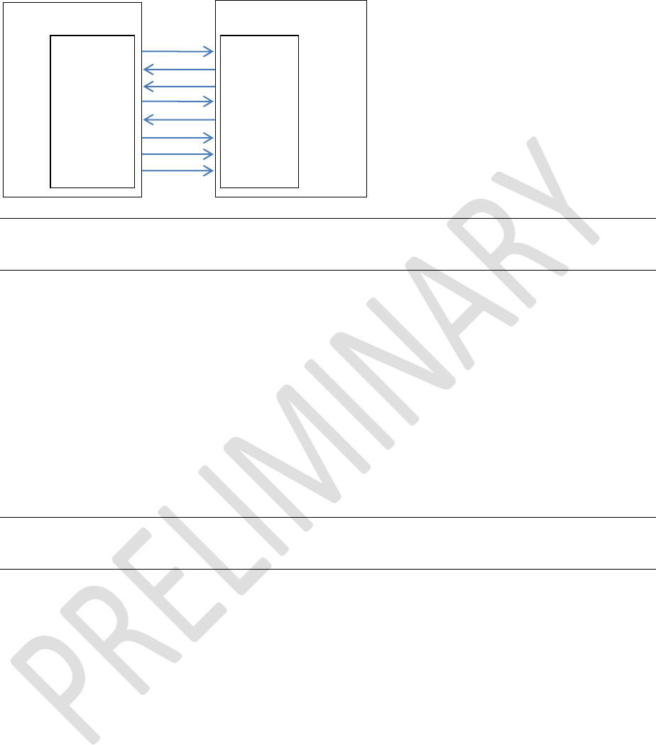
The module communicates with the customer application using the following signals:
Port /TXD of the application sends data to the module’s UART_RX signal line
Port /RXD of the application receives data from the module’s UART_TX signal line
Enhanced Class 1 Bluetooth v2.1 Module
User’s Guide
Americas: +1-800-492-2320 Option 2
Europe: +44-1628-858-940
Hong Kong: +852-2923-0610
www.lairdtech.com/wireless
13
CONN-GUIDE-BT740_v0.2
Note: The serial module output is at 3.3 V CMOS logic levels. Level conversion must be added to
interface with an RS232 level compliant interface.
Some serial implementations link CTS and RTS to remove the need for handshaking. Laird does not
recommend linking CTS and RTS other than for testing and prototyping. If these pins link and the host
sends data at the point that the BT740 deasserts its RTS signal, then there is a significant risk that
internal receive buffers will overflow, leading to an internal processor crash. This also leads to a drop in
connection and may require a power cycle to reset the module. Laird recommends to follow the correct
CTS/RTS handshaking protocol for proper operation.
4.2 SPI Bus
The module is a slave device that uses terminals SPI_MOSI, SPI_MISO, SPI_CLK, and SPI_CSB. This
interface programs firmware updates at the factory. Laird supplies a PC-based utility to allow a firmware
upgrade over the UART port. Laird highly recommends that customers use this method for updating
firmware.
Note: The designer should be aware that no security protection is built into the hardware or firmware
associated with this port, so the terminals should not permanently connect in a PC application.
4.3 PCM Interface
PCM_OUT, PCM_IN, PCM_CLK, and PCM_SYNC carry up to three bi-directional channels of voice data,
each at 8 k samples/s. The format of the PCM samples can be 8-bit A-law, 8-bit μ-law, 13-bit linear, or16-
bit linear. The PCM_CLK and PCM_SYNC terminals can configure as inputs or outputs depending on
whether the module is the master or slave of the PCM interface. Please contact a Laird FAE for further
details.
The module is compatible with the Motorola SSI TM interface and interfaces directly to PCM audio
devices including the following:
4.3.1 Compatible Codec Chips
OKI 7702 single channel A-law and μ-law CODEC
Winbond W681360 13 bit linear CODEC
BT740
UART_TX
UART_RX
UART_CTS
UART_RTS
UART_DSR
UART_DTR
UART_RI
UART_DCD
Application -
Host
/RXD
/TXD
/RTS
/CTS
/DTR
/DSR
/RING
/DCD

Enhanced Class 1 Bluetooth v2.1 Module
User’s Guide
Americas: +1-800-492-2320 Option 2
Europe: +44-1628-858-940
Hong Kong: +852-2923-0610
www.lairdtech.com/wireless
14
CONN-GUIDE-BT740_v0.2
4.4 General Purpose I/O and ADC
4.4.1 GPIO
Laird provides seven lines of programmable bi-directional input/outputs (I/O) that can be accessed either
via the UART port or Over The Air (OTA) from a second Bluetooth unit. These can be used as data inputs
or to control external equipment. By using these in OTA mode, a BT730 module can be used for control
and data acquisition without the need for any additional host processor. Each of the GPIO[3:9] ports can
independently configure to be either an input or output. A selection of ports can be accessed
synchronously.
The ports power from VCC. The mode of these lines can be configured and the lines are accessed via S
Registers 623 to 629.
4.4.2 ADC
The BT740 provides access to two 8-bit ADCs (Analogue 0 and 1). These provide an input range of 0 mV
to 1,800 mV, which are read using the S registers 701 and 702.
Suitable external scaling and over-voltage protection should be incorporated in your design. The module
provides five samples per second at the UART with a baud rate of 115,200 or above.

Enhanced Class 1 Bluetooth v2.1 Module
User’s Guide
Americas: +1-800-492-2320 Option 2
Europe: +44-1628-858-940
Hong Kong: +852-2923-0610
www.lairdtech.com/wireless
15
CONN-GUIDE-BT740_v0.2
5 AT COMMAND SET
5.1 Introduction to AT Commands
This chapter describes the ‘AT’ protocol used to control and configure the BT740-Sx Bluetooth modules
after it is configured to present an ‘AT’ protocol instead of the alternate multipoint packet-based interface.
The Multipoint Protocol is also described in this document.
The protocol is similar to the industry standard Hayes AT protocol used in telephony modems, as both
types of devices are connection oriented. The extended AT command set makes the Laird device
performs the three core actions of a Bluetooth device: establish Bluetooth connections, pair, and inquire.
Many other provided AT commands perform ancillary functions, such as trusted device database
management and S Register maintenance.
Just like telephony modems, the Laird device powers up in an unconnected state and only responds via
the serial interface. In this state the Laird device can respond to Bluetooth Inquiries. Then, just like
controlling a modem, the host issues AT commands which map to various Bluetooth activities. These AT
commands have appropriate counterparts in the alternate multipoint packet based protocol which also
achieve the same goal.
The nature of ‘AT’ protocol allows it to control and manage only one connection at a time; this is in
contrast to the multipoint packet protocol which can simultaneously control many connections. The main
advantage ‘AT’ protocol offers is simplicity.
The module has a serial interface through which the ‘AT’ protocol channels, which can be configured for
baud rates from 1200 up to 921600 and has an RF communications end point. The default baud rate for
AT command mode modules is 9600 bps.
The RF communications endpoint has a concept of connected and unconnected modes and the ‘AT’
protocol at the serial interface has a concept of command and data modes. This leads to the matrix of
states shown below.
RF Unconnected
RF Connected
Command Mode
Allowed
Allowed
Data Mode
Illegal
Allowed
The combination ‘Data + RF Unconnected Mode’ does not make sense and is ignored.
Navigation between these states uses the AT command/responses, described in detail in subsequent
sections.
There are many references to the term ‘S Register’ in the rest of this document. These are an array of
integer values stored in non-volatile memory which are used to configure the module so that it behaves in
a certain way after powering. These ‘S Registers’ have two attributes; a value and an ID. The ‘ID’ is a
positive integer number used in appropriate commands to read/write the values.
5.2 AT Protocol Mode
5.2.1 AT Protocol Assumptions
The CSR (Cambridge Silicon Radio) Bluetooth chipset in Laird devices has limited memory resources.
Therefore it is NOT proposed that there be full implementation of the AT protocol as seen in modems.

Enhanced Class 1 Bluetooth v2.1 Module
User’s Guide
Americas: +1-800-492-2320 Option 2
Europe: +44-1628-858-940
Hong Kong: +852-2923-0610
www.lairdtech.com/wireless
16
CONN-GUIDE-BT740_v0.2
The claim made for this device is that it has a protocol similar to an AT modem. In fact, the protocol is
similar enough so that existing source code written for modems can be used with very little modification
with a Laird device.
Therefore the following assumptions are made:
All commands terminate by the carriage return character 0x0D, represented by the string <cr> in
subsequent sections. It cannot be changed at runtime.
All responses from the Laird device have carriage return and linefeed characters preceding and
appending the response. These dual character sequences have the values 0x0D and 0x0A
respectively and are represented by the string <cr,lf>.
All Bluetooth addresses are represented by a fixed 12 digit case insensitive hexadecimal string.
All Bluetooth Device Class codes are represented by a fixed 6 digit case insensitive hexadecimal
string.
Most new Bluetooth specific commands are identified by the string +BTx, where x is generally a
mnemonic of the intended functionality.
5.2.2 Protocol Activation
Depending on the variant of the module, the AT protocol needs to activate so that on power up it presents
this protocol interface instead of the alternate multipoint protocol.
The method that is always available and works is activation via S Register 255 in multipoint mode (and
mapped to 9255 in AT mode), where setting a value of 1 selects multipoint packet protocol and a value of
2 selects AT protocol.
Note: Changes to this S register store in non-volatile memory at time of change and does not require
the AT&W command (or the equivalent in multipoint mode CMD_STORE_REG) to commit to
non-volatile memory.
Optionally, some firmware variants allow a value of 0 in this S Register and in this case on power up the
protocol selection depends on the state of one of the GPIO pins (user settable) so that one state forces
AT and the other forces multipoint.
5.3 AT Commands and Responses
This section describes all available AT commands. Many commands require mandatory parameters and
some take optional parameters. These parameters are integer values, strings, Bluetooth addresses or
device classes. The following convention is used when describing the various AT commands, and the
response to a command is also stated.
<bd_addr>
A 12 character Bluetooth address consisting of ASCII characters ‘0’ to ‘9’, ‘A’ to ‘F’
and ‘a’ to ‘f’.
<devclass>
A 6 character Bluetooth device class consisting of ASCII characters ‘0’ to ‘9’, ‘A’ to
‘F’ and ‘a’ to ‘f’.
N
A positive integer value.
M
An integer value which could be positive or negative, which can be entered as a
decimal value or in hexadecimal if preceded by the ‘$’ character.
E.g. the value 1234 can also be entered as $4D2
<string>
A string delimited by double quotes. E.g. "Hello World". The " character MUST be
supplied as delimiters.

Enhanced Class 1 Bluetooth v2.1 Module
User’s Guide
Americas: +1-800-492-2320 Option 2
Europe: +44-1628-858-940
Hong Kong: +852-2923-0610
www.lairdtech.com/wireless
17
CONN-GUIDE-BT740_v0.2
<uuid>
A 4 character UUID number consisting of ASCII characters ‘0’ to ‘9’, ‘A’ to ‘F’ and
‘a’ to ‘f’.
5.3.1 Enter Local Command Mode
Command:
^^^
Response:
<cr,lf>OK<cr,lf>
Description:
When in data + connected mode, the host can force the device into a command +
connected mode so that AT Commands can issue to the device while a connection
establishes. The S2 register specifies the character in this escape sequence, so it can
change. The escape sequence guard time sets at compile time to 100 milliseconds.
Please refer to the Dropping Connections section for more related information.
In modems this escape sequence is typically “{delay}+{delay}+{delay}+{delay}”, and
configures by default to avoid confusion when the module is providing access to a
modem.
5.3.2 Command Mode Status Check
Command:
AT
Response:
<cr,lf>OK<cr,lf>
Description:
<cr,lf>OK<cr,lf>
5.3.3 Accept Incoming Connection (Answer Call)
Command:
ATA
Response:
<cr,lf>CONNECT 123456789012,<uuid>,<<cr,lf>
Where <uuid> is the profile with the established connection.
Description:
Accept an incoming connection, which is indicated by the unsolicited string
<cr,lf>RING 123456789012<cr,lf>, where 123456789012 is the Bluetooth address of
the connecting device.
5.3.4 Make Outgoing Connection
Command:
ATD<bd_addr>,<uuid>
Response:
<cr,lf>CONNECT 123456789012,<uuid>,><cr,lf>
Or
<cr,lf>NO CARRIER<cr,lf>
Description:
Make a connection to device with Bluetooth address <bd_addr> and profile <uuid>.
The <uuid> is an optional parameter which specifies the UUID of the profile server to
attach to, and if not supplied then uses the default UUID for SPP (1101).
The UUIDs in the following table are allowed:
Profile Name
UUID
Serial Port
1101
HID
1124
HDP
Use appropriate canned HDP commands
instead

Enhanced Class 1 Bluetooth v2.1 Module
User’s Guide
Americas: +1-800-492-2320 Option 2
Europe: +44-1628-858-940
Hong Kong: +852-2923-0610
www.lairdtech.com/wireless
18
CONN-GUIDE-BT740_v0.2
5.3.5 Enable/Disable Echo
Command:
ATEn
Response:
<cr,lf>OK<cr,lf>
Or
<cr,lf>ERROR nn<cr,lf>
Description:
This command enables or disables the echo of characters to the host. The default echo
condition sets via S Register 506. This command does not affect the S Register 506.
0
Disable echo.
1
Enable echo.
All other values of n generate an error.
5.3.6 Drop Connection
Command:
ATH
Response:
<cr,lf>NO CARRIER<cr,lf>
Or
<cr,lf>OK<cr,lf>
Description:
Drop an existing connection or reject an incoming connection indicated by the
unsolicited RING message. If a connection does not exist then the response is OK.
5.3.7 Information
Command:
ATIn
Response:
For recognized values of n.
<cr,lf>As Appropriate<cr,lf>OK<cr,lf>
All other values of n generate
<cr,lf> Laird Technologies Inc (c)2010 <cr,lf> OK<cr,lf>
Description:
This returns the information in the following table about the Laird device. The list is not
exhaustive as there are some values of ‘n’ which generate information for use by Laird
Support.
Table 5-1: Laird device information
Index
Description
0
The product name/variant.
1
The underlying CCL Stack version information.
3
The Laird firmware revision
Format A.B.C.F.G
(See 333 for further details)
333
The full Laird firmware revision
Format A.B.C.D.E.F.G, where
A = Hardware Platform
B = Major Stack Version Number (Changes when CCL stack changes :
see ATi1)
C = Major App Version Number (Changes when number of profiles
change)

Enhanced Class 1 Bluetooth v2.1 Module
User’s Guide
Americas: +1-800-492-2320 Option 2
Europe: +44-1628-858-940
Hong Kong: +852-2923-0610
www.lairdtech.com/wireless
19
CONN-GUIDE-BT740_v0.2
Index
Description
D = Developer ID
E = Branch ID
F = Build Number (divisible by 10 for production releases and Odd for
Engineering)
G = Twig Number (will normally be 0, but minor releases on sub-
branches is non-zero)
4
A 12 digit hexadecimal number corresponding to the Bluetooth address
of the Laird device.
6
The maximum size of trusted device database.
9
0 if not in a connect state and 1 if in a connect state.
11
The reason why a “NO CARRIER” results in the most recent attempt at
making an outgoing connection. Where the response values are as
follows:
3 = Normal disconnection
13
Current Sniff parameters in two lines as follows
A,B,C,D
A,B,C,D
Where first line is in units of milliseconds and the second in baseband
slots.
A = Attempt (see S Reg 73, 561 in AT Mode)
B = Timeout (see S Reg 74, 562 in AT Mode))
C = Minimum Interval (see S Reg 75, 563 in AT Mode)
D = Maximum Interval (see S reg 76, 564 in AT Mode)
21
Current discoverable mode:
0 = Not Discoverable
1 = Generic Discoverable mode
2 = Limited Discoverable mode
22
Current connectable mode:
0 = Not Connectable
1 = Connectable
23
Same as (9) above.
0 if not in a connect state and 1 if in a connect state.
42
Current state of the module
14 = Not discoverable and not connectable and not in connection
18 = Connected mode
174 = Connectable and Discoverable
173 = Connectable only
172 = Discoverable only
56
The number of devices in the trusted device database in format a,b
where ‘a’ is the number of devices in the ‘rolling’ database and ‘b’ in the
‘persistant’ database.
100
Returns the hardware ID (100 for BTM4xx platform)
201
UART receive buffer and hardware handshaking information in the
format:

Enhanced Class 1 Bluetooth v2.1 Module
User’s Guide
Americas: +1-800-492-2320 Option 2
Europe: +44-1628-858-940
Hong Kong: +852-2923-0610
www.lairdtech.com/wireless
20
CONN-GUIDE-BT740_v0.2
Index
Description
A,B,C
Where
A = UART receive buffer size
B = Threshold at which the RTS output line deasserts
C = Threhsold at which the RTS output line re-asserts again.
202
The number of times the UART_DSR input line has been detected to
toggle since the module was powered or reset via appropriate
commands in AT and MP mode.
224-239
Memory Diagnostics information in the format “A,B” where A is the size
of pmalloc block and B is the number that are free. Low ‘B’ values imply
trhe module is operating at the limits of it’s heap resource.
5.3.8 Enter Data Mode When Connected and in Command Mode
Command:
ATO
Response:
<cr,lf>CONNECT<cr,lf>
Or
<cr,lf>ERROR nn<cr,lf>
Description:
Return to data mode. Assume that the module is in data mode after it receives an OK.
Responds with an error if there is no Bluetooth connection.
5.3.9 Set S Register
Command:
ATSn=m
Response:
<cr,lf>OK<cr,lf>
Or
<cr,lf>ERROR nn<cr,lf>
Description:
As with modems, the Laird Bluetooth module employs a concept of registers used to
store parameters, such as escape sequence character, inquiry delay time, etc.
The value part ‘m’ can enter as decimal or hexadecimal. A hexadecimal value is
specified via a ‘$’ leading character. For example, $1234 is a hexadecimal number.
When S register values change, the changes are not normally stored in non-volatile
memory UNTIL the AT&W command is used (unless specifically stated otherwise).
Note that AT&W does not affect some S registers; for example 520 to 525, or 9240 to
9255, as they are updated in non-volatile memory when the command processes.
5.3.10 Read S Register Value in Decimal or Hex
Command:
ATSn?<$>
Response:
For recognised values of n:
<cr,lf>As Appropriate<cr,lf>OK<cr,lf>
For unrecognised values of n:
<cr,lf>ERROR nn<cr,lf>
Description:
This returns the current value of register n. If the optional $
character supplies after the ?, then the returned value is
hexadecimal with a leading $. For example, the value 1000 returns

Enhanced Class 1 Bluetooth v2.1 Module
User’s Guide
Americas: +1-800-492-2320 Option 2
Europe: +44-1628-858-940
Hong Kong: +852-2923-0610
www.lairdtech.com/wireless
21
CONN-GUIDE-BT740_v0.2
as $3E8
5.3.11 Read S Register’s Valid Range
Command:
ATSn=?
Response:
For recognised values of n:
<cr,lf>nnnn..mmmm<cr,lf>OK<cr,lf>
For unrecognised values of n:
<cr,lf>ERROR nn<cr,lf>
Description:
This returns the valid range of values for register n.
5.3.12 Send Data to Peer When In Command Mode
Command:
ATX<string>
Response:
<cr,lf>OK<cr,lf>
Or if a connection does not exist
<cr,lf>ERROR 56<cr,lf>
Description:
This command sends data to the remote device when in local command and
connected mode.
If a non-printable ASCII character needs sent, then insert the escape sequence \hh
where hh are two hexadecimal digits. The three character sequence \hh converts
into a single byte before transmission to the peer.
Note: For HID connections, the entire <string> is deemed to be a single HID report.
5.3.13 Factory Default (Full)
Command:
AT&F*
Response:
<cr,lf>OK<cr,lf>
Or
<cr,lf>ERROR nn<cr,lf>
Description:
This command erases all user parameters in non-volatile memory.
The new settings become active after a reset.
5.3.14 Factory Default (Preserve Uart Settings)
Command:
AT&F+
Response:
<cr,lf>OK<cr,lf>
Or
<cr,lf>ERROR nn<cr,lf>
Description:
This command erases all user parameters in non-volatile memory except S Registers
520 to 525, and 9240 to 9255. This means that the trusted device database clears, but
‘AT’ protocol moderetains and UART config (baudrate, stopbits etc) is preserved.
The new protocol and settings become active after a reset.

Enhanced Class 1 Bluetooth v2.1 Module
User’s Guide
Americas: +1-800-492-2320 Option 2
Europe: +44-1628-858-940
Hong Kong: +852-2923-0610
www.lairdtech.com/wireless
22
CONN-GUIDE-BT740_v0.2
5.3.15 Factory Default (Preserve Protocol Setting)
Command:
AT&F*AT*
Response:
<cr,lf>OK<cr,lf>
Or
<cr,lf>ERROR nn<cr,lf>
Description:
This command erases all user parameters in non-volatile memory except S Register
9255. This means that the trusted device database clears, but ‘AT’ protocol mode
retains and UART parameters reset to factory default settings.
The new protocol and settings become active after a reset.
5.3.16 Factory default (Full, then change into MP mode)
Command:
AT&F*MP*
Response:
<cr,lf>OK<cr,lf>
Or
<cr,lf>ERROR nn<cr,lf>
Description:
This command erases all user parameters in non-volatile memory including S Register
9255 and S Reg 9255 is set to 1 for MP mode. This means that the trusted device
database clears, and protocol sets to MP mode and all UART parameters are reset to
factory default settings.
The new protocol and settings become active after a reset.
5.3.17 Write S Registers To Non-Volatile Memory
Command:
AT&W
Response:
<cr,lf>OK<cr,lf>
Or
<cr,lf>ERROR nn<cr,lf>
Description:
Writes current S Register values to non-volatile memory so that they retain over a
power cycle.
5.3.18 Write <String> To Blob(0)
Command:
AT+BTB=<string>
Response:
<cr,lf>OK<cr,lf>
Or
<cr,lf>ERROR nn<cr,lf>
Description:
This command clears BLOB(0) first and then <string> appended to that BLOB after the
string de-escapes. This allows binary data to load into the BLOB buffer for
subsequent processing using the AT+BTBnnnn command syntax.

Enhanced Class 1 Bluetooth v2.1 Module
User’s Guide
Americas: +1-800-492-2320 Option 2
Europe: +44-1628-858-940
Hong Kong: +852-2923-0610
www.lairdtech.com/wireless
23
CONN-GUIDE-BT740_v0.2
5.3.19 Append <String> To Blob(0)
Command:
AT+BTB+<string>
Response:
<cr,lf>OK<cr,lf>
Or
<cr,lf>ERROR nn<cr,lf>
Description:
This command appends <string> BLOB(0) after the string de-escapes. This allows
binary data to load into the BLOB buffer for subsequent processing using the
AT+BTBnnnn command syntax.
5.3.20 Action And Process Data In Blob(0)
Command:
AT+BTBnnnn
Response:
<cr,lf>OK<cr,lf>
Or
<cr,lf>ERROR nn<cr,lf>
Description:
This command processes BLOB(0) as per the action specified by ‘nnnn’. The actions
are described briefly as per the table below (more details in the MP protocol section):
Index
Action
0
Clear Blob(0)
1
Get byte count in Blob(0)
2
Destructively read Blob(0). Data sends so that non-printable data
bytes are escaped with \hh.
3
Save Blob(0) as Hid Descriptor(0) in non-volatile memory
4
Load Blob(0) as Hid Descriptor(0) from non-volatile memory
5
Save Blob(0) as Hid Service Name in non-volatile memory
6
Load Blob(0) as Hid Service name from non-volatile memory
7
Commit Blob(0) as Enhanced Inquiry Data
8
Save Blob(0) as Enhanced Inquiry Data in non-volatile memory, to be
used automatically after subsequent resets
9
Load Blob(0) from the Enhanced Inquiry Data from non-volatile
memory.

Enhanced Class 1 Bluetooth v2.1 Module
User’s Guide
Americas: +1-800-492-2320 Option 2
Europe: +44-1628-858-940
Hong Kong: +852-2923-0610
www.lairdtech.com/wireless
24
CONN-GUIDE-BT740_v0.2
5.3.21 Remove Trusted Device
Command:
AT+BTD<bd_addr>
Response:
<cr,lf>OK<cr,lf>
Or
<cr,lf>ERROR nn<cr,lf>
Description:
This command removes the specified device from the list of trusted devices in the non-
volatile database. If the device is not in the database then the response is still an OK.
Error response is for when the address is not a 12 character hex string.
5.3.22 Remove All Trusted Devices
Command:
AT+BTD*
Response:
<cr,lf>OK<cr,lf>
Or
<cr,lf>ERROR nn<cr,lf>
Description:
This command removes all devices from the list of trusted devices in the non-volatile
database. The device does not ask for confirmation.
WARNING: If you make a connection, the link key caches in the underlying stack. So
if you subsequently delete the key using AT+BTD* and immediately
request an authenticated connection to the same device, then the
connection may be established. To ensure this does not happen, send
ATZ after the AT+BTD*.
5.3.23 Get the Remote Friendly Name
Command:
AT+BTF<bd_addr>
Response:
<cr,lf>Friendly Name
<cr,lf>OK<cr,lf>
Or
<cr,lf>ERROR nn<cr,lf>
Description:
This command gets the remote friendly name of the specific address.
If the friendly name has non printable characters (including the character “) then those
characters escape into a 3 character ‘\hh’ sequence.
5.3.24 Enable Connectable Mode
Command:
AT+BTG
Response:
<cr,lf>OK<cr,lf>
Or
<cr,lf>ERROR nn<cr,lf>
Description:
Enable page scanning only and wait for a connection from any device. Inquiry scans
are disabled.
The page scan window and interval timing derives from S Reg 9009 and 9010.
Use ATi21 and ATi22 to determine the discoverable and connectable modes at any
time.

Enhanced Class 1 Bluetooth v2.1 Module
User’s Guide
Americas: +1-800-492-2320 Option 2
Europe: +44-1628-858-940
Hong Kong: +852-2923-0610
www.lairdtech.com/wireless
25
CONN-GUIDE-BT740_v0.2
5.3.25 Inquire
Command:
AT+BTI
Response:
<cr,lf>12346789012
<cr,lf>12345678914
<cr,lf>OK<cr,lf>
Description:
This makes the device perform an inquiry for ‘duration’ milliseconds and ‘max’ number
of unique responses, where S register 517 specifies ‘duration’ and S register 518
specifies ‘max’. Only the Bluetooth address of responding devices is listed.
5.3.26 Inquire And Display Devclass Too
Command:
AT+BTIV
Response:
<cr,lf>12346789012,123456
<cr,lf>12345678914,123456
<cr,lf>OK<cr,lf>
Description:
As per AT+BTI but the response includes the device class code for all inquiry
responses.
5.3.27 Inquire and Get Friendly Names Too
Command:
AT+BTIN
Response:
<cr,lf>12346789012,123456,"Laird BT Module"
<cr,lf>12345678914,123456, “Nokia N70"
<cr,lf>OK<cr,lf>
Description:
As per AT+BTI but the response includes the device class code and friendly name for
all inquiry responses. The friendly name strings are in UTF-8 format as per the
Bluetooth specification.
5.3.28 Inquire with Enhanced Inq Resp
Command:
AT+BTIE
Response:
<cr,lf>12346789012,123456,””,-45,"\0A\08Laird FEF"
<cr,lf>12345678914,123456,“",-75,””
<cr,lf>OK<cr,lf>
Description:
As per AT+BTI but the response includes the device class code, RSSI, and the
enhanced inquiry information. The friendly name is not acquired, as it is a time-
expensive procedure and therefore an empty string sends as a placeholder.
5.3.29 Set Pincode or Passcode
Command:
AT+BTK=<string>
Response:
<cr,lf>OK<cr,lf>
Or
<cr,lf>ERROR nn<cr,lf>
Description:
This command provides a passkey when PIN? 12345678 or PASSKEY? 12345678
indications receive asynchronously.

Enhanced Class 1 Bluetooth v2.1 Module
User’s Guide
Americas: +1-800-492-2320 Option 2
Europe: +44-1628-858-940
Hong Kong: +852-2923-0610
www.lairdtech.com/wireless
26
CONN-GUIDE-BT740_v0.2
The string length must be in the range 1 to 16, for PIN? otherwise an error returns.
The string length must be exactly 6 characters, for PASSKEY? otherwise an error
returns and each character MUST be a decimal digit in the range 0 to 9.
If there is no ongoing pairing in progress, then the <string> stores in non-volatile
memory and may be used in subsequent legacy pairing attempts. To delete the
pincode stored in non-volatile memory, submit the command with an empty string. A
stored value is not used for a PASSKEY? Event.
5.3.30 Reject Yes/No Simple Secure Pairing
Command:
AT+BTKN
Response:
<cr,lf>OK<cr,lf>
Or
<cr,lf>ERROR nn<cr,lf>
Description:
When the module configures for ‘Display with Yes/No’ security via S Register 9006,
this command conveys a ‘NO’ for the simple pairing procedure. This command sends
as a result of receiving a “PASSKEY? 2 <bd_addr>” asynchronous response.
5.3.31 Accept Yes/No Simple Secure Pairing
Command:
AT+BTKY
Response:
<cr,lf>OK<cr,lf>
Or
<cr,lf>ERROR nn<cr,lf>
Description:
When the module configures for ‘Display with Yes/No’ security via S Register 9006
then this command conveys a ‘YES’ for the simple pairing procedure. This command
sends as a result of receiving a “PASSKEY? 2 <bd_addr>” asynchronous response.
5.3.32 Set Friendly Name in Non-Vol Memory
Command:
AT+BTN=<string>
Response:
<cr,lf>OK<cr,lf>
Or
<cr,lf>ERROR nn<cr,lf>
Description:
This sets the default friendly name of this device as seen by other devices. It stores in
non-volatile memory. Use AT+BTN? To read it back. An empty string (“”) deletes the
string from non-volatile memory which forces the use of the default friendly name.
5.3.33 Read Friendly Name From Non-Vol Memory
Command:
AT+BTN?
Response:
<cr,lf>My FriendlyName<cr,lf>
<cr,lf>OK<cr,lf>
Or
<cr,lf>ERROR nn<cr,lf>
Description:
Read the friendly name from non-volatile memory.

Enhanced Class 1 Bluetooth v2.1 Module
User’s Guide
Americas: +1-800-492-2320 Option 2
Europe: +44-1628-858-940
Hong Kong: +852-2923-0610
www.lairdtech.com/wireless
27
CONN-GUIDE-BT740_v0.2
5.3.34 Enable Connectable+Discoverable Mode
Command:
AT+BTP
Response:
<cr,lf>OK<cr,lf>
Or
<cr,lf>ERROR nn<cr,lf>
Description:
Enable page and inquiry scanning and wait for a connection from any device.
The page scan window and interval timing derives from S Reg 9009 and 9010.
The inquiry scan window and interval timing derives from S Reg 9007 and
9008.
5.3.35 Enable Discoverable Mode Only
Command:
AT+BTQ
Response:
<cr,lf>OK<cr,lf>
Or
<cr,lf>ERROR nn<cr,lf>
Description:
Set discoverable mode only by enabling inquiry scanning.
The inquiry scan window and interval timing derives from S Reg 9007 and 9008.
Use ATi21 and ATi22 to determine the discoverable and connectable modes at any
time.
5.3.36 List Trusted Device
Command:
AT+BTT?
Response:
<cr,lf>12346789012
<cr,lf>12345678913
<cr,lf>12345678914
<cr,lf>OK<cr,lf>
Or
<cr,lf>ERROR nn<cr,lf>
Description:
This command lists the contents of both the ‘rolling’ and the ‘persist’ trusted device
database. The link key does NOT display so the response is as shown above. If the
list is empty, only the OK response sends; otherwise an OK terminates the list. Use
the command ATI6 to read the maximum size of the trusted device database.
Note: All new successful pairings automatically store in the ‘rolling’ database. If
the database is full, then the oldest is deleted to make room for the new
one. To ensure a link key is never deleted, transfer it to the ‘persist’
database using the command AT+BTT<bd_addr> described in detail later.

Enhanced Class 1 Bluetooth v2.1 Module
User’s Guide
Americas: +1-800-492-2320 Option 2
Europe: +44-1628-858-940
Hong Kong: +852-2923-0610
www.lairdtech.com/wireless
28
CONN-GUIDE-BT740_v0.2
5.3.37 List Trusted Device
Command:
AT+BTTn?
Response:
<cr,lf>12346789012
<cr,lf>12345678913
<cr,lf>12345678914
<cr,lf>OK<cr,lf>
Or
<cr,lf>ERROR nn<cr,lf>
Description:
This command lists the contents of either the ‘rolling’ or the ‘persist’ trusted device
database, where n=0 for the rolling database and 1 for the persist database. The link
key does NOT display so the response is as shown below. If the list is empty then just
the OK response sends; otherwise an OK terminates the list. Use the command ATI6
to read the maximum size of the trusted device database.
5.3.38 Transfer Device To ‘Persist’ List
Command:
AT+BTT<bd_addr>
Response:
<cr,lf>OK<cr,lf>
Or
<cr,lf>ERROR nn<cr,lf>
Description:
When a successful pairing occurs, the new link key automatically stores in the ‘rolling’
database where if the database is full, the oldest device is deleted. This poses a risk of
a trusted device automatically deleting, especially when the module is in ‘just works’
simple pairing mode and so pairings can occur without the host being involved and so
there is a definite risk of link key deletion.
This command transfers a device specified via the address supplied to the ‘persist’
database so that a trusted device is never deleted automatically.
5.3.39 Initiate a Pairing
Command:
AT+BTW<bd_addr>
Response:
<cr,lf>OK<cr,lf>
Or
<cr,lf>ERROR nn<cr,lf>
Description:
This initiates pairing with a device whose Bluetooth address is <bd_addr>. An OK
response sends immediately and when the PIN or PASSCODE is required.
Asynchronous indications send to the host in the form PIN? <bd_addr> or PASSKEY?
<bd_addr> or PAIR ? <bd_addr> where the address confirms the device with which the
pairing is to be performed. To supply a PIN or passcode, use the AT+BTK command.
To respond with a YES or NO, use the command AT+BTKY or AT+BTKN respectively.
For a successful pairing, the link key automatically stores in the ‘rolling’ database which
can be queried using the AT+BTT0? Command.
Note: The “OK” response sends immediately on receipt of the AT+BTW command. On
pairing completion, an unsolicited message sends to the host in the form PAIR n
<bd_addr>, where n is 0 for a successful pairing.

Enhanced Class 1 Bluetooth v2.1 Module
User’s Guide
Americas: +1-800-492-2320 Option 2
Europe: +44-1628-858-940
Hong Kong: +852-2923-0610
www.lairdtech.com/wireless
29
CONN-GUIDE-BT740_v0.2
5.3.40 Disable Connectable And Discoverable Mode
Command:
AT+BTX
Response:
<cr,lf>OK<cr,lf>
Or
<cr,lf>ERROR nn<cr,lf>
Description:
Disable page/inquiry scanning. This means it does not accept incoming connections or
inquiry requests. More specifically it negates the effect of AT+BTQ, AT+BTG and
AT+BTP commands.
Use ATi21 and ATi22 to determine the discoverable and connectable modes at any
time.
5.3.41 HDP: Associate The Agent With Manager
Command:
AT+HAAhhhh
Response:
<cr,lf>OK<cr,lf>
Or
<cr,lf>ERROR nn<cr,lf>
Description:
This is a Health Device Profile (HDP Agent related command. Refer to Application
Examples for details). Please note ERROR 59 implies that the profile has not been
activated which means bit 2 in S Reg 9003 is not set AND S Reg 9070 is not 0.
‘hhhh’ is obtained as a response to the AT+HAB command.
5.3.42 HDP: Bind Manager to Agent
Command:
AT+HAB<bd_addr>,iiii
Response:
<cr,lf>hhhh<cr,lf>OK<cr,lf>
Or
<cr,lf>ERROR nn<cr,lf>
Description:
This is a Health Device Profile (HDP Agent related command. Refer to Application
Examples for details). Please note ERROR 59 implies that the profile has not been
activated which means bit 2 in S Reg 9003 is not set AND S Reg 9070 is not 0.
‘iiii’ is the nominal code for the data specialization.
5.3.43 HDP: Disassociate The Agent From Manager
Command:
AT+HADhhhh
Response:
<cr,lf>OK<cr,lf>
Or
<cr,lf>ERROR nn<cr,lf>
Description:
This is a Health Device Profile (HDP Agent related command. Refer to Application
Examples for details). Please note ERROR 59 implies that the profile has not been
activated which means bit 2 in S Reg 9003 is not set AND S Reg 9070 is not 0.

Enhanced Class 1 Bluetooth v2.1 Module
User’s Guide
Americas: +1-800-492-2320 Option 2
Europe: +44-1628-858-940
Hong Kong: +852-2923-0610
www.lairdtech.com/wireless
30
CONN-GUIDE-BT740_v0.2
5.3.44 HDP: Endpoint Definition In SDP Record
Command:
AT+HAE,iiii,”endpointname”
Response:
<cr,lf>OK<cr,lf>
Or
<cr,lf>ERROR nn<cr,lf>
Description:
This is a Health Device Profile (HDP Agent related command. Refer to Application
Examples for details). Please note ERROR 59 implies that the profile has not been
activated which means bit 2 in S Reg 9003 is not set AND S Reg 9070 is not 0.
It inserts details in the SDP record.
5.3.45 HDP: Read Attribute Value In Agent
Command:
AT+HAGhhhh,aaaa,ssss
Response:
<cr,lf>OK<cr,lf>
Or
<cr,lf>ERROR nn<cr,lf>
Description:
This is a Health Device Profile (HDP Agent related command. Refer to Application
Examples for details). Please note ERROR 59 implies that the profile has not been
activated which means bit 2 in S Reg 9003 is not set AND S Reg 9070 is not 0.
5.3.46 HDP: Activate SDP Record For Agent
Command:
AT+HAL
Response:
<cr,lf>OK<cr,lf>
Or
<cr,lf>ERROR nn<cr,lf>
Description:
This is a Health Device Profile (HDP Agent related command. Refer to Application
Examples for details). Please note ERROR 59 implies that the profile has not been
activated which means bit 2 in S Reg 9003 is not set AND S Reg 9070 is not 0.
5.3.47 HDP: Trigger Agent Scan Report
Command:
AT+HARhhhh,pppp[,aaaa[,aaaa[…]]]
Response:
<cr,lf>OK<cr,lf>
Or
<cr,lf>ERROR nn<cr,lf>
Description:
This is a Health Device Profile (HDP Agent related command. Refer to Application
Examples for details). Please note ERROR 59 implies that the profile has not been
activated which means bit 2 in S Reg 9003 is not set AND S Reg 9070 is not 0.

Enhanced Class 1 Bluetooth v2.1 Module
User’s Guide
Americas: +1-800-492-2320 Option 2
Europe: +44-1628-858-940
Hong Kong: +852-2923-0610
www.lairdtech.com/wireless
31
CONN-GUIDE-BT740_v0.2
5.3.48 HDP: Write Attribute Value To Agent
Command:
AT+HAShhhh,aaaa,ssss,ddddd
Response:
<cr,lf>OK<cr,lf>
Or
<cr,lf>ERROR nn<cr,lf>
Description:
This is a Health Device Profile (HDP Agent related command. Refer to Application
Examples for details). Please note ERROR 59 implies that the profile has not been
activated which means bit 2 in S Reg 9003 is not set AND S Reg 9070 is not 0.
5.3.49 HDP: Endpoint Definition in SDP Record (Manager)
Command:
AT+HME,iiii,”endpointname”
Response:
<cr,lf>OK<cr,lf>
Or
<cr,lf>ERROR nn<cr,lf>
Description:
This is a Health Device Profile (HDP Manager related command. Refer to Application
Examples for details. Please note ERROR 59 implies that the profile has not been
activated which means bit 2 in S Reg 9003 is not set AND S Reg 9070 is not 1.
5.3.50 HDP: Endpoint Definition in SDP Record (Manager)
Command:
AT+HME,iiii,”endpointname”
Response:
<cr,lf>OK<cr,lf>
Or
<cr,lf>ERROR nn<cr,lf>
Description:
This is a Health Device Profile (HDP Manager related command. Refer to Application
Examples for details). Please note ERROR 59 implies that the profile has not been
activated which means bit 2 in S Reg 9003 is not set AND S Reg 9070 is not 1.
5.3.51 HDP: Activate SDP Record For Agent (Manager)
Command:
AT+HML
Response:
<cr,lf>OK<cr,lf>
Or
<cr,lf>ERROR nn<cr,lf>
Description:
This is a Health Device Profile (HDP Manager related command. Refer to Application
Examples for details). Please note ERROR 59 implies that the profile has not been
activated which means bit 2 in S Reg 9003 is not set AND S Reg 9070 is not 1.

Enhanced Class 1 Bluetooth v2.1 Module
User’s Guide
Americas: +1-800-492-2320 Option 2
Europe: +44-1628-858-940
Hong Kong: +852-2923-0610
www.lairdtech.com/wireless
32
CONN-GUIDE-BT740_v0.2
5.3.52 HDP: Read Attribute Value (Manager)
Command:
AT+HMGhhhh,oooo,aaaa
Response:
<cr,lf>OK<cr,lf>
Or
<cr,lf>ERROR nn<cr,lf>
Description:
This is a Health Device Profile (HDP Manager related command. Refer to Application
Examples for details). Please note ERROR 59 implies that the profile has not been
activated which means bit 2 in S Reg 9003 is not set AND S Reg 9070 is not 1.
5.3.53 HDP: Send Time to Agent (Manager)
Command:
AT+HMThhhh,ttttttt
Response:
<cr,lf>OK<cr,lf>
Or
<cr,lf>ERROR nn<cr,lf>
Description:
This is a Health Device Profile (HDP Manager related command. Refer to Application
Examples for details). Please note ERROR 59 implies that the profile has not been
activated which means bit 2 in S Reg 9003 is not set AND S Reg 9070 is not 1.
5.3.54 Add To Trusted Device Database (Rolling)
Command:
AT+KY<addr>,<link_key>
Response:
<cr,lf>OK<cr,lf>
Or
<cr,lf>ERROR nn<cr,lf>
Description:
This command adds (or replaces) the <addr> and<link_key> pair to the rolling trusted
device database. <addr> is a 12 hex digit Bluetooth address and <link_key> is a 32
hex digit random number. For more details, see the multipoint command
CMD_TRUSTED_DB_ADD.
5.3.55 Read The Link Key For Address Specified
Command:
AT+KY<addr>?
Response:
<cr,lf>OK<cr,lf>
Or
<cr,lf>ERROR nn<cr,lf>
nn is 49 if the device is not in the trusted device database
nn is 45 is S Reg 47 is not set to 1
Description:
This command reads the link key from the trusted device database for device with
address <addr>. The link key information sends only if S Reg 47 ( 9047) is set to 1.
This command is gated through S Reg 47 (9047) to get confirmation from the user that
they acknowledge that security is compromised by allowing link keys to be read.

Enhanced Class 1 Bluetooth v2.1 Module
User’s Guide
Americas: +1-800-492-2320 Option 2
Europe: +44-1628-858-940
Hong Kong: +852-2923-0610
www.lairdtech.com/wireless
33
CONN-GUIDE-BT740_v0.2
5.3.56 Unsolicited/Async Responses
The ‘AT’ Protocol is a command/response type of protocol. This means that the Laird device normally
only responds to AT commands and in addition only responds to one AT command at a time.
Under special circumstances, unsolicited responses send to the host. They are described
in the following subsections. Each unsolicited response is prefixed and postfixed by a cr,lf
two character sequence.
Command:
No Command. This is a status message.
Response:
RING
Description:
This string sends to the host every second repeatedly when a remote device
initiates a serial port connection. The fully qualified string is in the form RING
012345678901, where 012345678901 is a 12 digit hexadecimal number which
corresponds to the remote device’s Bluetooth address.
The host responds with the ATA command to accept the connection or reject it
using the ATH command.
If S Register 0 is set to a non-zero value then the incoming SPP connection
automatically accepts after the number of RINGS specified in S Register 0 sends
to the host.
Only incoming SPP connections invoke a RING response. Connections on other
profiles automatically accepts.
Command:
No Command. This is a status message.
Response:
PIN ? <bd_addr>
Description:
This response sends to the host during a legacy pairing negotiation (pre BT
version 2.1 compliant devices).
The fully qualified string is PIN? 012345678901, where 012345678901is the
Bluetooth address of the peer device. In response, the host must supply a pin
code using the AT+BTK command.
Command:
No Command. This is a status message.
Response:
PASSKEY ? N <bd_addr>[,passcode]
Description:
This response sends to the host during a simple secure pairing (SSP) negotiation
and when the module is configured appropriately via S Register 9006.
Where N is 1 for the host to display the passkey supplied, 2 for the host to
respond with either the command AT+BTKY or AT+BTKN and 3 for the host to
respond with AT+BTK=”nnnnnn”.
The fully qualified string is :
PASSKEY? 1 012345678901,123456 where 012345678901 is the Bluetooth
address of the peer device and 123456 is the passcode to display to the user.
PASSKEY? 2 012345678901,123456 where 012345678901 is the Bluetooth
address of the peer device and 123456 is the passcode to display to the user.
PASSKEY? 3 012345678901 where 012345678901 is the Bluetooth address of the
peer device and the user echoes the passcode displayed on the peer device, or
agree with the other user to enter the same random 6 digit passcode at both ends.
Command:
No Command. This is a status message.
Response:
PAIR N <bd_addr>
Description:
This response sends to the host on completion (success or otherwise) of a pairing
process. If pairing succeeds then ‘n’ = 0; if a timeout occurs then ‘n’=1; and for all
other unsuccessful outcomes the value is 2.

Enhanced Class 1 Bluetooth v2.1 Module
User’s Guide
Americas: +1-800-492-2320 Option 2
Europe: +44-1628-858-940
Hong Kong: +852-2923-0610
www.lairdtech.com/wireless
34
CONN-GUIDE-BT740_v0.2
The parameter <bd_addr> is the address of the peer device if available.
Command:
No Command. This is a status message.
Response:
RX<string>
Description:
This response sends to the host when the unit is in online-command mode, S
Register 531 is set to 3, and data arrives from a peer. For profiles other than SPP
(1101), use S Register 531 as a flag. If it is 0, then the profile is serviced in
‘canned’ mode and in that case RX”” responses do not send and neither does
the ATX<string> command needed to send data.
If the data from the string contains non-printable characters (for example ASCII 0
to 31 and ASCII 128 to 255), then those characters translate into a 3 character
escape sequence starting with ‘\’. For example, the embedded <cr><lf> sequence
sends as the 6 character string \0D\0A.
If the data contains the character ‘"’ then it sends as \22.
If the data contains the character ‘\’ then it sends as \5C
Command:
No Command. This is a status message.
Response:
HDA:ASSOCIATED hhhh,iiii,cccc,sssssss
Description:
This is a Health Device Profile (HDP Agent) related asynchronous response.
Refer to Application Examples for details.
Command:
No Command. This is a status message.
Response:
HDA:DISASSOCIATED hhhh
Description:
This is a Health Device Profile (HDP Agent) related asynchronous response.
Refer to Application Examples for details.
Command:
No Command. This is a status message.
Response:
HDA:TIME hhhh,ttttttt
Description:
This is a Health Device Profile (HDP Agent) related asynchronous response.
Refer to Application Examples for details.
Command:
No Command. This is a status message.
Response:
HDM:ASSOCIATED hhhh,iiii,cccc,sssssss
Description:
This is a Health Device Profile (HDP Manager) related asynchronous response.
Refer to Application Examples for details.
Command:
No Command. This is a status message.
Response:
HDM:DISASSOCIATED hhhh
Description:
This is a Health Device Profile (HDP Manager) related asynchronous response.
Refer to Application Examples for details.
Command:
No Command. This is a status message.
Response:
HDM:ASSOCIATED hhhh,iiii,cccc,sssssss
Description:
This is a Health Device Profile (HDP Agent) related asynchronous response.
Refer to Application Examples for details.
Command:
No Command. This is a status message.
Response:
HDM:SCANREPORT hhhh:pppp …..<more>…
Description:
This is a Health Device Profile (HDP Agent) related asynchronous response.
Refer to Application Examples for details.

Enhanced Class 1 Bluetooth v2.1 Module
User’s Guide
Americas: +1-800-492-2320 Option 2
Europe: +44-1628-858-940
Hong Kong: +852-2923-0610
www.lairdtech.com/wireless
35
CONN-GUIDE-BT740_v0.2
6 S REGISTERS
All S registers are accessible when operating in AT protocol mode, but in MP protocol mode the only
visible S Registers are listed as ‘Standard’ and ‘Special’.
‘Standard’ and ‘AT’ S Registers share the same numbers in some cases. For this reason, the Standard
and Special registers access from AT mode by offsetting 9000. For example, the standard S register 3 for
profiles is read by using the command ATS9003? and set using ATS9003=n.
6.1 Standard S Registers
This section details all the standard configuration ‘S’ registers. Minimum and Maximum values are given
in decimal, unless the value is prefixed by 0x, in that case the value is in hexadecimal.
Table 6-1: Standard configuration S registers
RegNo
Dec
(Hex)
Min
Max
Category
Description
3 (03)
0
3
Profiles
Server Profile record Mask
Bit 0 = SPP
Bit 1 = HID
Bit 2 = HDP
If HID enables, see S Reg 39 for further configuration
options in terms of device or host implementation.
If HDP enables, see S Reg 70 for further configuration
options in terms of Agent or Manager services.
Note: Depending on the firmware build, some profiles are
not available; in that case setting or clearing the
appropriate bit in this register has no effect as that
bit is ignored.
4 (04)
0
1
GAP
Default Connectable Mode on power up/reset
0: Disable
1: Enable
5 (05)
0
2
GAP
Default Discoverable Mode on power up/reset
0 : Disable
1 : Enable General Discoverable mode (uses GIAC =
0x9E8B33)
2 : Enable Limited Discoverable mode (used LIAC =
0x9E8B00))
6 (06)
12
15
GAP
Security
IO Capability
Default Security Mode on power up/reset
12 = SSP + IO_CAP_NO_INPUT_NO_OUTPUT
13 = SSP + IO_CAP_DISPLAY_YES_NO
14 = SSP + IO_CAP_KEYBOARD_ONLY
15 = SSP + IO_CAP_DISPLAY_ONLY
7 (07)
12
2560
GAP
Inquiry Scan Interval in units of msec

Enhanced Class 1 Bluetooth v2.1 Module
User’s Guide
Americas: +1-800-492-2320 Option 2
Europe: +44-1628-858-940
Hong Kong: +852-2923-0610
www.lairdtech.com/wireless
36
CONN-GUIDE-BT740_v0.2
RegNo
Dec
(Hex)
Min
Max
Category
Description
8 (08)
12
2560
GAP
Inquiry Scan Window in units of msec
9 (09)
12
2560
GAP
Page Scan Interval in units of msec
10 (0A)
12
2560
GAP
Page Scan Window in units of msec
11 (0B)
23
4096
SPP
RFCOMM frame size for all RFCOMM based profiles.
23-512 range has a granularity of 1; 512 to 4096 range
has a granularity of 4.
For example: Setting 4095 sets a value of 4092 (round
down new values).
Note: Testing and calculations by our stack vendor show
that the incremental benefit above 990 is not worth
the downside of handling larger payloads.
12 (0C)
1
30
General / GAP
Link supervision Timeout in seconds.
This value only reads on power up when the profiles are
registers. After changing the value it needs committed to
non-volatile memory using AT&W or
CMD_SREG_STORE and then the module needs a power
cycle.
14 (0E)
0
1
SSP
Auto Accept Channel Setup. If this is 1, incoming
connections automatically accept.
If this is 1, EVT_CONNECTION_SETUP events do not
send to the host when an incoming connection arrives.
32 (20)
0
4
SPP
Master/Slave role preference for SPP incoming
connections.
0 = Don’t Care
1 = Prefer Master
2 = Prefer Slave
3 = Must be Master
4 = Must be Slave
33 (21)
0
4
SPP
Master/Slave role preference for SPP outgoing
connections.
0 = Don’t Care
1 = Prefer Master
2 = Prefer Slave
3 = Must be Master
4 = Must be Slave
34 (22)
0
7
SPP
If Profiles Reg 3 bit 0 is set and this is not 0, then
incoming SPP connections are allowed up to the number
specified in this register.
35 (23)
0
7
SPP
If Profiles Reg 3 bit 0 is set and this is not 0, then outgoing

Enhanced Class 1 Bluetooth v2.1 Module
User’s Guide
Americas: +1-800-492-2320 Option 2
Europe: +44-1628-858-940
Hong Kong: +852-2923-0610
www.lairdtech.com/wireless
37
CONN-GUIDE-BT740_v0.2
RegNo
Dec
(Hex)
Min
Max
Category
Description
SPP connections are allowed up to the number specified
in this register
36 (24)
0
1
Profiles
Enable DeviceID SDP record, and use the vid/pid as per
registers 37 and 38.
37 (25)
0
0xFFF
F
Profiles
USB Vendor ID to use in the DeviceID record
38 (26)
0
0xFFF
F
Profiles
USB Product ID to use in the DeviceID record
39 (27)
-2
2
HID
Significant if the HID profile enables via Register 3.
Negative values imply that HID HOST Profile is
registered.
Value 0 and above imply HID DEVICE Profile is registered
and 0 = standard KEYBOARD device (104 keys).
All other positive values are associated with custom HID
Device Descriptors which are preloaded using the
CMD_BLOBMANAGE or AT+BTB command into non-
volatile memory.
There is MIMIMAL validation of the HID Descriptor that a
user uploads. It is extremely important that a properly
constructed descriptor is uploaded for storage in
nonvolatile memory
Note: If HID functionality is not included in the firmware
build, then this register is not available.
40 (28)
0
0x1F
SPP
On SPP connection, this specifies the initial state of the
following modem control lines sent to the peer.
Bit 0 := RTR (RTS/CTS)
Bit 1 := RTC (DTR/DSR)
Bit 2 := DV (DCD)
Bit 3 := IC (Ring Indicate RI)
Bit 4 := FC (Reserved – Future use)
41 (29)
0
0xFF
HID
HID Device options: Bit MASK Values.
When the module configures as an HID device
(Sreg39>=0) and Sreg3 has right value, then this and S
Reg 42 modify optional flags that are exposed in the
service record that tell the host what capabilities are built
into the device.
The capabilities expose as bit masks. If a bit is set in this
register, then the corresponding bit in SReg42 is the value
used for that capability.
The flag masks are :
HID_SIF_BATTERYPOWER 0x01

Enhanced Class 1 Bluetooth v2.1 Module
User’s Guide
Americas: +1-800-492-2320 Option 2
Europe: +44-1628-858-940
Hong Kong: +852-2923-0610
www.lairdtech.com/wireless
38
CONN-GUIDE-BT740_v0.2
RegNo
Dec
(Hex)
Min
Max
Category
Description
HID_SIF_BOOTDEVICE 0x02
HID_SIF_NORMALLYCONNECTABLE 0x04
HID_SIF_RECONNECTINITIATE 0x08
HID_SIF_REMOTEWAKE 0x10
HID_SIF_SDPDISABLE 0x20
HID_SIF_VIRTUALCABLE 0x40
HID_SIF_SUPERVISIONTIMEOUT 0x80
For more details about what these flags do and mean, see
the HID profile specification available on the BT SIG
website.
Note: If HID functionality is not included in the firmware
build, then this register is not available.
42 (2A)
0
0xFF
HID
HID Device options: bit values.
See description for SReg 41.
Note: If HID functionality is not included in the firmware
build, then this register is not available.
43 (2B)
0
63
HID
Country Code exposed in HID Device Descriptor which
have the following values:
Not Supported
Arabic
Belgian
Canadian_Bilingua
Canadian_French
Czech Republic
Danish
Finnish
French
German
Greek
Hebrew
Hungary
International_ISO
Italian
Japan_ Katakana
Korean
Latin American
0
1
2
3
4
5
6
7
8
9
10
11
12
13
14
15
16
17
Netherlands_Dutch
Norwegian
Persian_Farsi
Poland
Portuguese
Russia
Slovakia
Spanish
Swedish
Swiss_French
Swiss_German
Switzerland
Taiwan
Turkish_Q
UK
US
Yugoslavia
Turkish_F
18
19
20
21
22
23
24
25
26
27
28
29
30
31
32
33
34
35
Note: If HID functionality is not included in the firmware
build, then this register is not available.
44 (2C)
0x6
161
0x7A7
A
HID
Language Code exposed in the HID Device Descriptor
which have the following values. Each value contains
ASCII values of two lower case characters. For example
‘en’== 0x656E

Enhanced Class 1 Bluetooth v2.1 Module
User’s Guide
Americas: +1-800-492-2320 Option 2
Europe: +44-1628-858-940
Hong Kong: +852-2923-0610
www.lairdtech.com/wireless
39
CONN-GUIDE-BT740_v0.2
RegNo
Dec
(Hex)
Min
Max
Category
Description
Note: If HID functionality
is not included in
the firmware build,
then this register is
not available.
Afar
Abkhazian
Afrikaans
Amharic
Arabic
Assamese
Aymara
Azerbaijani
Bashkir
Byelorussia
n
Bulgarian
Bihari
Bislama
Bengali
Tibetan
Breton
Catalan
Corsican
Czech
Welsh
Danish
German
Bhutani
Greek
English
Esperanto
Spanish
Estonian
Basque
Persian
Finnish
Fiji
Faeroese
French
Frisian
Irish
Gaelic
Galician
Guarani
Gujarati
Hausa
Hindi
Croatian
Hungarian
Armenian
Zulu
‘aa’
‘ab’
'af’
‘am’
‘ar’
‘as’
‘ay’
‘az’
‘ba’
‘be’
‘bg’
‘bh’
‘bi’
‘bn’
‘bo’
‘br’
‘ca’
‘co’
‘cs’
‘cy’
‘da’
‘de’
‘dz’
‘el’
‘en’
‘eo’
‘es’
‘et’
‘eu’
‘fa’
‘fi’
‘fj’
‘fo’
‘fr’
‘fy’
‘ga’
‘gd’
‘gl’
‘gn’
‘gu’
‘ha’
‘hi’
‘hr’
‘hu’
'hy'
‘zu’
Interlingua
Interlingue
Inupiak
Indonesian
Icelandic
Italian
Hebrew
Japanese
Yiddish
Javanese
Georgian
Kazakh
Greenlandic
Cambodian
Kannada
Korean
Kashmiri
Kurdish
Kirghiz
Latin
Lingala
Laothian
Lithuanian
Latvian
Malagasy
Maori
Macedonian
Malayalam
Mongolian
Moldavian
Marathi
Malay
Maltese
Burmese
Nauru
Nepali
Dutch
Norwegian
Occitan
Oromo
Oriya
Punjabi
Polish
Pashto
Portuguese
‘ia’
‘ie’
‘ik’
‘in’
‘is’
‘it’
‘iW’
‘ja’
‘ji’
‘jw’
‘ka’
‘kk’
‘kl’
‘km’
‘kn’
‘ko’
‘ks’
‘ku’
‘ky’
‘la’
‘ln’
‘lo’
‘lt’
‘lv’
‘mg’
‘mi’
‘mk’
‘ml’
‘mn’
‘mo’
‘mr’
‘ms’
‘mt’
‘my’
‘na’
‘ne’
‘nl’
‘no’
‘oc’
‘om’
‘or’
‘pa’
‘pl’
‘ps’
‘pt’
Quechua
Rhaeto_Romanc
e
Kirundi
Romanian
Russian
Kinyarwanda
Sanskrit
Sindhi
Sangro
Serbo_Croatian
Singhalese
Slovak
Slovenian
Samoan
Shona
Somali
Albanian
Serbian
Siswati
Sesotho
Sudanese
Swedish
Swahili
Tamil
Tegulu
Tajik
Thai
Tigrinya
Turkmen
Tigrinya
Turkmen
Tagalog
Setswana
Tonga
Tatar
Twi
Ukrainian
Urdu
Uzbek
Vietnamese
Volapuk
Wolof
Xhosa
Yoruba
Chinese
‘qu’
‘rm’
‘rn’
‘ro’
‘ru’
‘rw’
‘sa’
‘sd’
‘sg’
‘sh’
‘si’
‘sk’
‘sl’
‘sm’
‘sn’
‘so’
‘sq’
‘sr’
‘ss’
‘st’
‘su’
‘sv’
‘sw’
‘ta’
‘te’
‘tg’
‘th’
‘ti’
‘tk’
‘tl’
‘tn’
‘to’
‘tr’
‘ts’
‘tt’
‘tw’
‘uk’
‘ur’
‘uz’
‘vi’
‘vo’
‘wo’
‘xh’
‘yo’
‘zh’

Enhanced Class 1 Bluetooth v2.1 Module
User’s Guide
Americas: +1-800-492-2320 Option 2
Europe: +44-1628-858-940
Hong Kong: +852-2923-0610
www.lairdtech.com/wireless
40
CONN-GUIDE-BT740_v0.2
RegNo
Dec
(Hex)
Min
Max
Category
Description
45 (2D)
0
0x3F
F
HID
Primary Language exposed in the HID Device Descriptor
and the value is specified as follows ( where the values
are in hexadecimal), refer to the HID specification for a
complete list:
NEUTRAL
ARABIC
BULGARIAN
CATALAN
CHINESE
CZECH
DANISH
GERMAN
GREEK
ENGLISH
SPANISH
FINNISH
FRENCH
HEBREW
HUNGARIAN
ICELANDIC
ITALIAN
JAPANESE
KOREAN
DUTCH
NORWEGIAN
POLISH
PORTUGUESE
ROMANIAN
RUSSIAN
SERBIAN
CROATIAN
SLOVAK
ALBANIAN
SWEDISH
THAI
TURKISH
URDU
INDONESIAN
UKRAINIAN
BELARUSIAN
00
01
02
03
04
05
06
07
08
09
0a
0b
0c
0d
0e
0f
10
11
12
13
14
15
16
18
19
1a
1a
1b
1c
1d
1e
1f
20
21
22
23
SLOVENIAN
ESTONIAN
LATVIAN
LITHUANIAN
FARSI
ARMENIAN
AZERI
BASQUE
MACEDONIAN
VIETNAMESE
AFRIKAANS
GEORGIAN
FAEROESE
HINDI
MALAY
KAZAK
SWAHILI
UZBEK
TATAR
BENGALI
PUNJABI
GUJARATI
ORIYA
TAMIL
TELUGU
KANNADA
MALAYALAM
ASSAMESE
MARATHI
SANSKRIT
KONKANI
MANIPURI
SINDHI
KASHMIRI
NEPALI
24
25
26
27
29
2b
2c
2d
2f
2a
36
37
38
39
3e
3f
41
43
44
45
46
47
48
49
4a
4b
4c
4d
4e
4f
57
58
59
60
61
Note: If HID functionality is not included in the firmware
build, then this register is not available.

Enhanced Class 1 Bluetooth v2.1 Module
User’s Guide
Americas: +1-800-492-2320 Option 2
Europe: +44-1628-858-940
Hong Kong: +852-2923-0610
www.lairdtech.com/wireless
41
CONN-GUIDE-BT740_v0.2
RegNo
Dec
(Hex)
Min
Max
Category
Description
46 (2E)
0
0x3F
HID
Sub Language exposed in the HID Device Descriptor and
the value is specified as follows for English ( where the
values are in hexadecimal); refer to the HID specification
for a complete list:
ENGLISH_US
ENGLISH_UK
ENGLISH_AUSTRALIAN
ENGLISH_CANADIAN
ENGLISH_NEWZEALAND
ENGLISH_IRELAND
ENGLISH_SOUTHAFRIC
A
ENGLISH_JAMAICA
ENGLISH_CARIBBEAN
ENGLISH_BELIZE
ENGLISH_TRINIDAD
ENGLISH_ZIMBABWE
ENGLISH_PHILIPPINES
01
02
03
04
05
06
07
08
09
0A
0B
0C
0D
Note: If HID functionality is not included in the firmware
build, then this register is not available.
47
0
1
Pairing
When this register is 1, in MP Mode it enables the
EVT_LINK_KEY_EX event to send to the host when the
module receives the CMD_TRUSTED_DB_IS_TRUSTED
command and in AT mode it enables the AT+KY?
command so that the link key information sends to the
host in the response.
By default this key is 0.
By setting this to 1, the customer acknowledges that
security can be compromised.
50..65
(32..41)
0
0 or
15
GPIO
This specifies the functionality attached to GPIO 0 to 15
appropriately.
50 for GPIO_0 onwards to 65 for GPIO_15.
Depending on the platform, if the GPIO does not
physically exist then the max value is 0.
The functionality is specified as follows:
0 : None (the pio hardware is not touched)
1 : Input
2 : Output (0 on reset)
3 : Output (1 on reset)
4 : Input Inverted
5 : Output Inverted (0 on reset)
6 : Output Inverted (1 on reset)

Enhanced Class 1 Bluetooth v2.1 Module
User’s Guide
Americas: +1-800-492-2320 Option 2
Europe: +44-1628-858-940
Hong Kong: +852-2923-0610
www.lairdtech.com/wireless
42
CONN-GUIDE-BT740_v0.2
RegNo
Dec
(Hex)
Min
Max
Category
Description
7 : UART RI Input (DTE) (Ring Indicate)
8 : UART DCD Input (DTE)
9 : UART DSR Input
10 : UART RI Output (DCE)
11 : UART DCD Output (DCE)
12 : UART DTR Output
13 : UART TX Buffer NOT Empty Output
14 : Input pin – Select Protocol 0=AT,1=MP
15 : Output pin – 0 for AT, 1 for MP
For all UART input/outputs (except 13, 14, & 15) there is
an implied inversion. A logical 1 applies to assert the
output, but by the time it hits the output pin or after it is
read, there is automatic inversion.
When writing to this location(s), validation prevents a write
if the new value is a UART functionality and the same
value already exists in another register. The best
approach to writing to this group of registers is to first
write 0 to all 16 registers and then write new values to all.
New values for these registers only come into effect after
a reset/power cycle.
For details of functionality 13, see section UART Host
Power Saving Facility which describes how this output
can be used to wake a UART host.
Contact the manufacturer for specific mapping and
functionality allocations.
70 (46)
0
1
HDP
If set to 0 then an HDP AGENT profile implements;
otherwise with 1, a HDP MANAGER implements.
In addition, bit 2 of Profiles S Reg3 has to be set.
Note: If HDP functionality is not included in the firmware
build, then this register is not available.
71 (47)
0
6500
0
HDP
HDP AGENT profile related.
This is the default time in milliseconds an HDP Agent
remains in associated state while there is no activity with
the HDP Manger.
If the value is 0, that is taken as infinite time.
This time is referenced when performing a new HDP
agent IEEE specialization binding with an HDP manager
Bluetooth. In AT mode see command AT+HAB, and in MP
mode see CMD_HDP_BIND
Note: If HDP functionality is not included in the firmware
build, then this register is not available.

Enhanced Class 1 Bluetooth v2.1 Module
User’s Guide
Americas: +1-800-492-2320 Option 2
Europe: +44-1628-858-940
Hong Kong: +852-2923-0610
www.lairdtech.com/wireless
43
CONN-GUIDE-BT740_v0.2
RegNo
Dec
(Hex)
Min
Max
Category
Description
72 (48)
48
1024
HDP
HDP Profile related.
This is the max TX pdu size and computes to the nearest
multiple of 16.
Note: If HDP functionality is not included in the firmware
build, then this register is not available.
73 (49)
0
2000
0
Sniff Mode /
Power Saving
Sniff Attempt Time in units of milliseconds. 0 means
disable.
This value must be less than half the Sniff Minimum
Interval (SReg 75).
The value stores in an 8 bit number and so a non-linear
algorithm converts between the value to the 8 bit number.
This means writing and reading may yield different values.
See section Sniff Mode Explained.
74 (4A)
1
4000
0
Sniff Mode /
Power Saving
Sniff Timeout Time in units of milliseconds. 0 means
disable.
The value stores in an 8 bit number and so a non-linear
algorithm converts between the value to the 8 bit number.
This means writing and reading may yield different values.
See section Sniff Mode Explained.
75 (4B)
1
4000
0
Sniff Mode /
Power Saving
Sniff Minimum Interval in units of milliseconds.
The value stores in an 8 bit number and so a non-linear
algorithm converts between the value to the 8 bit number.
This means writing and reading may yield differing values.
See section Sniff Mode Explained.
76 (4C)
1
4000
0
Sniff Mode /
Power Saving
Sniff Maximum Interval in units of milliseconds.
The value stores in an 8 bit number and so a non-linear
algorithm converts between the value to the 8 bit number.
This means writing and reading may yield differing values.
See section Sniff Mode Explained.
80 (50)
100
0
7500
0
UART Comms
UART latency time in microseconds.
In a connection, the data pump waits for X bytes
(specified by SReg 11) before transferring the data to the
air-side. In the event that the host sends fewer than X
bytes this has the potential of those bytes never being
transmitted.
Therefore, to cater for that scenario a timer detects how
long they sat in the buffer and if too long, send those
bytes air-side anyway. How long to wait is specified by
this S register. The timer starts once when a byte arrives
in an empty buffer, not every time a byte arrives in the
buffer.

Enhanced Class 1 Bluetooth v2.1 Module
User’s Guide
Americas: +1-800-492-2320 Option 2
Europe: +44-1628-858-940
Hong Kong: +852-2923-0610
www.lairdtech.com/wireless
44
CONN-GUIDE-BT740_v0.2
RegNo
Dec
(Hex)
Min
Max
Category
Description
81
10
80
UART Comms
Memory usage in percent for MP mode UART RX
processing. Leave to default value. Only change on
advice from manufacturer.
New values round up to the nearest 10.
This register controls how many memory blocks are
reserved when the module receives a flood of UART data
packets with small payloads.
82
2
99
UART
Comms
The UART interface in the module uses hardware
RTS/CTS handshaking to ensure that the low level
receive buffer does not overflow. This register specifies at
what fill percentage the RTS output line deasserts.
This value validates to ensure it is always more than
register 83.
In AT mode, use the command ATi201 to return a
response in the format X,Y,Z, where X is the actual size
of the UART receive buffer, Y is the RTS deassert
threshold, and Z is the RTS re-assert threshold.
83
1
98
UART
Comms
The UART interface in the module uses hardware
RTS/CTS handshaking to ensure that the low level
receive buffer does not overflow. This register specifies at
what fill percentage the RTS output line reasserts.
This value validates to ensure it is always less than
register 83.
In AT mode, use the command ATi201 to return a
response in the format X,Y,Z, where X is the actual size
of the UART receive buffer, Y is the RTS deassert
threshold, and Z is the RTS re-assert threshold.
84
0
3
UART
Comms
Configure UART Latency.
The default value of 0 configures the module for maximum
throughput at the expense of latency.
Select 1 for HIGH latency ( 25 ms polling of UART RX
buffer)
Select 2 for MEDIUM latency (8 ms polling of UART RX
buffer)
Select 3 for BEST latency (1 ms polling of UART RX
buffer)
Selecting 3 has a severe detrimental impact on
throughput.
Note: Polling times are correct as of this document.
Contact Laird for updates.
128 (80)
0
0xFF
FFFF
GAP
Module’s Class of Device.
If Profiles SReg3=2 (that is only HID Profile) and SReg39
sets for 0 (I.E. built in keyboard HID descriptor), then this

Enhanced Class 1 Bluetooth v2.1 Module
User’s Guide
Americas: +1-800-492-2320 Option 2
Europe: +44-1628-858-940
Hong Kong: +852-2923-0610
www.lairdtech.com/wireless
45
CONN-GUIDE-BT740_v0.2
RegNo
Dec
(Hex)
Min
Max
Category
Description
class of device is overridden with a value which specifies
a HID keyboard device.
Note: Most registers read by the firmware at reset. Hence the radio requires a reset after setting a
register for it to be effective. This means the relevant S Register set MUST commit to non-
volatile memory before initiating a reset. The S Registers store to non-volatile memory using
the command [CMD_STORE_SREG].

Enhanced Class 1 Bluetooth v2.1 Module
User’s Guide
Americas: +1-800-492-2320 Option 2
Europe: +44-1628-858-940
Hong Kong: +852-2923-0610
www.lairdtech.com/wireless
46
CONN-GUIDE-BT740_v0.2
6.2 Special S Registers (240 to 255)
Registers 240 to 255 inclusive are special in the sense that when written, the value automatically commits
to non-volatile memory.
Table 6-2: Special S registers
RegNo
Dec
(Hex)
Min
Max
Category
Description
240
(F0)
0
921600
UART
Comms
UART Baudrate
Writing 0 implies default baudrate which may be different for all
the different protocols as follows:
MP mode = 115200
AT mode = 9600
Automatically saves to non-volatile memory on write.
241
(F1)
1
1
UART
Comms
UART Handshaking.
1=CTS/RTS
Automatically saves to non- volatile memory on write.
242
(F2)
1
2
UART
Comms
UART Stopbits
Automatically saves to non- volatile memory on write.
243
(F3)
0
2
UART
Comms
UART Parity
0=None
1=Odd
2=Even
Automatically saved to non- volatile memory on write
255
(FF)
0
2
Protocol
Mode
Host Communications Protocol
0 = Select protocol based on the state of GPIO input pin.
1 = Multipoint Packet Protocol
2 = AT Protocol
If this register contains 0, then at least one S register in the
range 50 to 65 should be set to the value (14 =
PROTOCOL_MODE_IN) so that the GPIO pin corresponding to
that S Register automatically configures as an input and if on
power up, the state of that pin is 0, then AT protocol activates,
oitherwise MP.
If no GPIO pin is configured to specify protocol and the value in
this register is 0, then MP Protocol is selected.
Automatically saves to non-volatile memory on write.
All these S Registers, unless specifically mentioned, become effective after a power cycle or reset.

Enhanced Class 1 Bluetooth v2.1 Module
User’s Guide
Americas: +1-800-492-2320 Option 2
Europe: +44-1628-858-940
Hong Kong: +852-2923-0610
www.lairdtech.com/wireless
47
CONN-GUIDE-BT740_v0.2
6.3 ‘AT’ S Registers
These registers are specific to AT protocol operation only and are not accessible from MP protocol mode.
Any S Register marked ‘remapped’ is detailed with the descriptions of the mapped-to S Registers.
Table 6-3: 'AT' S registers
RegNo
Min
Max
Category
Description
0
0
15
SPP
Rings before auto answering an incoming SPP connection.
Setting 0 means a connection is not auto answered.
2
0x21
0x7E
SPP
Escape character used to change from data mode to
command parsing mode when in a data connection.
Three of these character enveloped by delays result in a
transition from data into command mode
504
0
1
General
This register controls what debug shows on the terminal
program during the connection process.
0 – All debug shown.
1 - Inhibits the printing of connection debug on the terminal
screen.
506
0
1
General
If this is set to 1, then AT commands echo back to the host.
This becomes effective after a power cycle. To make
immediate effect on echoes, use the command ATE0 or
ATE1.
Note: This register only specifies the initial state of echoes
on power up.
507
0
1
SPP
When set to 1, which is the default, the DSR modem status
input line enters command mode and/or drop a connection.
When set to 0 the DSR line is not checked for connection
related functionality. This is so that the input can convey a
digital status to the peer using S Registers 651/654 and
661/664 inclusive.
508
Remapped
GAP
To S Reg 9009 (9 in MP Mode see section Standard S
Registers )
509
Remapped
GAP
To S Reg 9010 (10 in MP Mode. See section Standard S
Registers ).
510
Remapped
GAP
To S Reg 9007 (7 in MP Mode. See section Standard S
Registers)
511
Remapped
GAP
To S Reg 9009 (8 in MP Mode. See section Standard S
Registers).
514
2
60
Pairing
Minimum time in seconds to wait for the conclusion of a
pairing operation.
517
2
60
Inquiry
Maximum time in seconds to perform an inquiry.
518
1
255
Inquiry
Maximum number of inquiry responses in an inquiry.

Enhanced Class 1 Bluetooth v2.1 Module
User’s Guide
Americas: +1-800-492-2320 Option 2
Europe: +44-1628-858-940
Hong Kong: +852-2923-0610
www.lairdtech.com/wireless
48
CONN-GUIDE-BT740_v0.2
RegNo
Min
Max
Category
Description
520
Remapped
UART
Comms
To S Reg 9240 (240 in MP Mode. See section Standard S
Registers).
521
Remapped
UART
Comms
To S Reg 9240 (240 in MP Mode. See section Standard S
Registers).
522
Remapped
UART
Comms
To S Reg 9241 (241 in MP Mode. See section Standard S
Registers).
523
Remapped
UART
Comms
To S Reg 9242 (242 in MP Mode. See section Standard S
Registers).
524
Remapped
UART
Comms
To S Reg 9243 (243 in MP Mode. See section Standard S
Registers).
530
1
60
SPP
Reconnect delay when configured as master in auto
connection mode.
531
0
3
SPP/
AT Parser
Specifies the AT Parser mode on connection establishment.
0 = Normal, that data exchanges between UART and RF.
1 = LOCAL_COMMAND. The AT interpreter parses UART
input and RF data is discarded.
2 = REMOTE_COMMAND. The AT interpreter parses RF
input and UART data is discarded. If S Reg 536 is not 1
then this register cannot be set to 2 and an ERROR
returns.
3= LOCAL_COMMAND. The AT interpreter parses UART
input and incoming RF data sends to the host using the
RX<string> asynchronous response.
561
Remapped
Sniff
Mode
To S Reg 9073 (73 in MP Mode. See section Standard S
Registers).
562
Remapped
Sniff
Mode
To S Reg 9074 (74 in MP Mode. See section
Standard S Registers).
563
Remapped
Sniff
Mode
To S Reg 9075 (75 in MP Mode see section
Standard S Registers).
564
Remapped
Sniff
Mode
To S Reg 9076 (76 in MP Mode. See section
Standard S Registers)
619
0
0xFFFF
GPIO
This specifies a write mask when ATS620=X sets multiple
GPIO states.
620
0
0xFFFF
GPIO
ATS620? reads all the GPIO states at once.
ATS620=X writes new GPIO states using the mask in S
Register 619.
621
0
0xFF
AIO
Reads and digitises the voltage on AIO0 and outputs it as
an 8 bit number on the terminal program.
622
0
0xFF
AIO
Reads and digitises the voltage on AIO1 and outputs it as

Enhanced Class 1 Bluetooth v2.1 Module
User’s Guide
Americas: +1-800-492-2320 Option 2
Europe: +44-1628-858-940
Hong Kong: +852-2923-0610
www.lairdtech.com/wireless
49
CONN-GUIDE-BT740_v0.2
RegNo
Min
Max
Category
Description
an 8 bit number on the terminal program.
651
-1
8
GPIO
-1 means no GPIO pin allocation.
See Note 1 and 3 below.
Requires firmware build 185 or newer.
652
-1
8
GPIO
-1 means no GPIO pin allocation.
See Note 1 and 3 below.
Requires firmware build 185 or newer.
653
-1
8
GPIO
-1 means no GPIO pin allocation.
See Note 1 and 3 below.
Requires firmware build 185 or newer.
654
-1
8
GPIO
-1 means no GPIO pin allocation.
See Note 1 and 3 below.
Requires firmware build 185 or newer.
661
-1
8
GPIO
-1 means no GPIO pin allocation.
See Note 2 and 3 below.
Requires firmware build 185 or newer.
662
-1
8
GPIO
-1 means no GPIO pin allocation.
See Note 2 and 3 below.
Requires firmware build 185 or newer.
663
-1
8
GPIO
-1 means no GPIO pin allocation.
See Note 2 and 3 below.
Requires firmware build 185 or newer.
664
-1
8
GPIO
-1 means no GPIO pin allocation.
See Note 2 and 3 below.
Requires firmware build 185 or newer.
717
2
15
GAP
Maximum time to wait for a remote friendly name to read
(AT+BTI command).
All these S Registers, unless specifically mentioned, become effective after a power cycle or reset.
Note 1: S Reg 651 to 654 take a GPIO pin number in the range 1 to 8 inclusive (or as per the full
range for the specific module) which maps from the RTR, RTC,DV,IC bits in the RFCOMM
Modem Control signal which exchanges for serial port profile. When a fresh Modem Control
Sig message arrives from the peer, if the corresponding S register is NOT -1 and the specific
GPIO pin is configured as an output (using S Reg 50 to 65 inclusive), then the state of the bit
outputs to that pin.
Note 2: S Reg 661 to 664 take a GPIO pin number in the range 1 to 8 inclusive (or as per the full
range for the specific module) which maps to the RTR, RTC,DV,IC bits in the RFCOMM
Modem Control signal which exchanges for serial port profile. If a GPIO pin specifies in one
of these S Registers and it changes state AND there is an SPP connection, then the state of
that input pin copies into an RFCOMM modem control message and sent to the peer.

Enhanced Class 1 Bluetooth v2.1 Module
User’s Guide
Americas: +1-800-492-2320 Option 2
Europe: +44-1628-858-940
Hong Kong: +852-2923-0610
www.lairdtech.com/wireless
50
CONN-GUIDE-BT740_v0.2
Note 3: This capability enables the state of between 2 and 4 (depends on the direction of the
connection) digital pins to exchange between peers without any host intervention.
7 ERROR CODES
7.1 Error Responses
All error responses from the device are in the form <cr,lf>ERROR nn<cr,lf>, where nn is a number in the
range 00 to 99 as follows:
Table 7-1: BTM Error Responses in AT Mode
Error
Description
01
Register not recognized
02
Value for register is out of range
03
Incoming call NOT pending
04
No call to connect to. This error code has meaning for ATO only
05
Syntax Error
06
Empty String
06
Device Class could not be stored
08
Invalid Device Class Code
09
Invalid Bluetooth Address
10
Could not set Service or Friendly name
11
PS Store Write
12
PS Store Read
13
Not Idle
14
Incorrect Mode
15
Already Scanning
16
Pairing is already in progress
17
NOT USED
18
NOT USED
19
NOT USED
20
Not safe to write to Non-volatile Store - Ongoing Bluetooth Connection
21
Link Key Cache is Empty
22
Link Key Database is Full
23
Malloc returned NULL - Resource Issue
24
Remote Address same as Local Address
25
Connection Setup Fail, DSR Not asserted
26
Unauthenticated licence
27
Max Responses (See S Register 518) too high. Memory allocation error
28
The length of Pin in AT+BTK is too long
29
Invalid Ring count specified for S Register 0 or 100. If S0<>0 and S100<>0 then S0
must be < S100
30
ADC Error
31
Analogue Value cannot be read as it is set for output
32
Analogue Value cannot be written as it is set for input
33
S Register Value is invalid

Enhanced Class 1 Bluetooth v2.1 Module
User’s Guide
Americas: +1-800-492-2320 Option 2
Europe: +44-1628-858-940
Hong Kong: +852-2923-0610
www.lairdtech.com/wireless
51
CONN-GUIDE-BT740_v0.2
Error
Description
34
Both L and R modifier cannot be specified in ATD command
35
Invalid Major Device Class – valid value in range 0x00 to 0x1F inclusive
36
Pairing in progress – Command cannot be actioned – try again later
37
Invalid Sniff parameter specified.
E.g. new Attempt value greater than MinInterval. Solution is to first increase
MinInterval and re-enter the Attempt value.
38
Get Remote Friendly name Failed
39
Failed to change mode to Multipoint
40
7 Bit mode requires parity to be even or odd
41
Stream Error
42
Stream Pending
43
Unknown AG command
44
Busy Try Later
45
Not Allowed
46
Invalid String
47
Generic Error
48
Inquiry in progress
49
Link Key Missing
50
String De-escape Error
51
Invalid Passcode (must be 6 decimal digits)
52
Invalid Pincode
53
Invalid UUID (must be 4 hex digits)
54
Connection in progress
55
Profile unsupported
56
No SPP Connection
57
I/O Mask is Zero (see SReg 619)
58
Invalid Friendly Name
59
Profile is not active
60
HDP : Invalid Handle
61
HDP : Unknown IEEE Nominal Code (Data Specialisation)
62
HDP : Report Error
63
HDP : Invalid IEEE Code
64
HDP : Invalid Parameter
65
HDP : Attribute not found
66
HDP : Invalid Number of Arguments
67
HDP : Object Closed
68
HDP : Association Failed
69
HDP : Too many Agents
70
HDP : Object Incomplete
71
HDP : PHDC Failed
72
HDP : PHDC Insufficient Resource
73
HDP : PHDC Invalid Parameter
74
HDP : PHDC Invalid State
75
HDP : PHDC Unknown

Enhanced Class 1 Bluetooth v2.1 Module
User’s Guide
Americas: +1-800-492-2320 Option 2
Europe: +44-1628-858-940
Hong Kong: +852-2923-0610
www.lairdtech.com/wireless
52
CONN-GUIDE-BT740_v0.2
Error
Description
99
Functionality yet to be coded (please report to manufacturer)

Enhanced Class 1 Bluetooth v2.1 Module
User’s Guide
Americas: +1-800-492-2320 Option 2
Europe: +44-1628-858-940
Hong Kong: +852-2923-0610
www.lairdtech.com/wireless
53
CONN-GUIDE-BT740_v0.2
8 MULTIPOINT PROTOCOL
8.1 Introduction to Multipoint Protocol
This chapter describes a packet based messaging interface which a host uses to send commands,
receive responses, receive asynchronous events and exchange multiplexed data with the Bluetooth serial
module, henceforth described as the module.
The module consists of a Bluetooth chipset with an approved Bluetooth stack which allows simultaneous
connections to a minimum of one slave and, depending on hardware build and conditions, up to seven
slaves. It also allows connections to multiple profiles to one or more slaves. Hence this document adopts
a concept of channels instead of slave connections. You can also view these channels as logical data
pipes.
The term ‘host’ in this document refers to any entity which is a source of command messages, sink for
response/event messages, and both source and sink for multiplexed data packets.
To further eliminate any confusion, when the terms ‘command message’ and ‘confirm message’ are used,
it implies a message from the host to the module. Likewise the terms ‘response message’ and ‘event
message’ imply a message from the module to the host.
There is an implied client/server model in the protocol described in this document and the host should
ensure that no new commands issue to the module until after a response is received for that command or
an appropriate timeout. If multiple commands are sent, they queue and process only after the oldest
command processes. Confirm messages do not have the same restrictions. Data packets do not follow
that model. It is likely that asynchronous event messages are sent before response messages but that
should not be taken as a signal to issue new commands. The only exception to this is when an unknown
command receives; in this case the transaction terminates by an UNKNOWN_COMMAND event.
This document does not describe how the packets are physically exchanged between the host and the
module. The transport medium could be either UART or USB. It also does not describe the format of any
envelope that may be required to reliably and quickly transfer the message packet between the host and
module.
This implies that when the packets proposed in this document are processed, they are assumed not to
contain any errors by either peer entities.
8.2 Flow control & Data Integrity
The transport mechanism streams in nature. If the transport medium is USB, then flow control and data
integrity is inherently provided by the USB protocol.
If the medium is UART, then it is assumed that there is a minimum of a five wire interface: RX, TX, CTS,
RTS, and GND. Any host attached to the UART of the module strictly observes CTS/RTS hardware
handshaking. Packet data integrity may or may not be provided depending on the build. For a UART
transport media, guaranteeing data integrity is at the severe expense of data throughput.

Enhanced Class 1 Bluetooth v2.1 Module
User’s Guide
Americas: +1-800-492-2320 Option 2
Europe: +44-1628-858-940
Hong Kong: +852-2923-0610
www.lairdtech.com/wireless
54
CONN-GUIDE-BT740_v0.2
8.3 Packet Format
This section describes the general format of incoming and outgoing packets.
The term ‘incoming’ henceforth implies packets sent by the host to the module and ‘outgoing’ in the
reverse direction. That is, the direction terminology is module (server) centric.
All packets have octet granularity. When an octet is described as containing bit fields, it shall be taken
that bit 0 is the least significant bit and bit 7 is the most significant bit.
Subfields in the packet which require multiple octets shall be ordered so that the lowest significant octet
transmits LAST over the transport media, unless specifically described otherwise – this is also referred to
as Big Endien format. For example, a 16-bit word value requires two octets within the packet and the first
transmitted octet corresponds to the upper byte. Similarly, a 6-byte Bluetooth address transports the most
significant byte first. If the order is reversed then it is specifically highlighted in the description of
appropriate packets.
Subfields which are data arrays shall be described with the ‘[ ]’ operator in descriptions which come in
subsequent chapters.
Apart from data packets, all command, confirm, respond and event packets are of fixed size. If there isn’t
enough data to fill a packet, then the packet fills with 0s. The protocol and fixed packet format is
optimized to ensure maximum data throughput over the air. Subsequent sections describe the packets in
detail.
8.4 Host to Module Packets
These are packets used to convey commands and confirms to the module or raw data to be sent over an
open Bluetooth connection.
8.5 Command & Confirm Packets
The format for command and confirm packets is displayed in Table 8-1.
Table 8-1: Command and confirm packets
Octet
Field
Description
0
LENGTH
Total length of this packet, including this octet
1
CHANNEL
Always zero
2
CMD_ID/CNF_ID
Described in the subsequent chapters and have CMD_ or CNF_
prefixes
3
FLOW_IN
Bit 0 to 6 specify a mask. A clear bit means the module should NOT
send any more packets to that corresponding SPP data channel.
Bit 7 is always zero and is used as an extension bit in the future.
It is assumed that the host is always able to receive a response or
status packet.
4..N
DATA[]
Data as required and has meaning specific to CMD_ID or CNF_ID.
For example, if the command is to make a connection to a peer
device, then it is at least a six octet array specifying the Bluetooth
address of the peer.
The value of CMD_ID is in the range of 0 to 63 and commands are queued until a previous command is
completed by sending a response packet to the host.

Enhanced Class 1 Bluetooth v2.1 Module
User’s Guide
Americas: +1-800-492-2320 Option 2
Europe: +44-1628-858-940
Hong Kong: +852-2923-0610
www.lairdtech.com/wireless
55
CONN-GUIDE-BT740_v0.2
The value of CNF_ID is in the range of 64 to 127 inclusive.

Enhanced Class 1 Bluetooth v2.1 Module
User’s Guide
Americas: +1-800-492-2320 Option 2
Europe: +44-1628-858-940
Hong Kong: +852-2923-0610
www.lairdtech.com/wireless
56
CONN-GUIDE-BT740_v0.2
Unknown command values result in an EVT_UNKNOWN_COMMAND event, with the command value
reflected in the data field. If the octet value is specified in the range 128 to 255 (0x80 to 0xFF), then
reflecting that value in the data field of an EVT_UNKNOWN_COMMAND instead of the COMMAND field
of a response packet guarantees that the packet is NOT mistakenly processed as an event.
Confirm packets are not queued by the UART packet processor in the module and are processed as soon
they are received. As an example, this allows passkeys and pincodes to submit to the module while a
response is awaited by the CMD_CONNECTION_MAKE command. In other words, confirm packets
always go to the head of the packet queue.
8.6 Data Packets
The format for data packets is displayed in Table 8-2 and can arrive at any time; that is, they do not
adhere to a client/server model. The only method by which the host can be stopped from sending this
message is by sending a zero value in the FLOW_OUT field of a response or status message. The
module is prepared to receive at least one data packet after deasserting the appropriate flow control bit.
Table 8-2: Data packet format
Octe
t
Field
Description
0
LENGTH
Total length of this packet, including this octet
1
CHANNEL
0 is an invalid value as this marks the packet as command/response or event.
1 to 7 are dedicated serial port profile connections.
128 is dedicated as Hid Device data channel.
All other channels are reserved for future use.
2..N
DATA[]
For channels 1 to 7, this data array unconditionally sends over the air in the
appropriate.
For channel 128 data is interpreted before appropriate HIT reports transmit.
8.7 Packet Processing Logic
Data and Confirm packets process as soon as they are received.
A command packet processes in a transaction, meaning it processes as soon as it is received if and only
if there is no previous command processing and waiting for completion. Completion happens when an
appropriate response packet is sent to the host. If a command transaction is currently in progress, then
the packet inserts in a first-in, first-out queue. When an on-going command transaction completes, the
queue is inspected and, if non-empty, the oldest queued command is processed.
8.7.1 Module to Host Packets
These packets convey responses or events from the module and raw data received over an open
Bluetooth connection or internal data source. Response packets are always a result of a command
packet and event packets asynchronously send to the host as and when required. The host shall ensure
that it is always ready to accept response and event packets, especially event packets as they can be
sent at any time including where there is an incomplete transaction in progress.

Enhanced Class 1 Bluetooth v2.1 Module
User’s Guide
Americas: +1-800-492-2320 Option 2
Europe: +44-1628-858-940
Hong Kong: +852-2923-0610
www.lairdtech.com/wireless
57
CONN-GUIDE-BT740_v0.2
8.7.2 Response Packets
The format for response packets is displayed in Table 8-3.
Table 8-3: Response packet format
Octet
Field
Description
0
LENGTH
Total length of this packet, including this octet
1
CHANNEL
Always zero
2
CMD_ID
Echoed from the command packet (Shall be > 0 and < 128)
3
FLOW_OUT
Bit 0 to 6 specify a mask. A clear bit means the host should NOT send any
more packets to that corresponding data channel.
Bit 7 is always 0 and is an extension bit in the future.
4
STATUS
Zero means success, otherwise see section “STATUS values”
N..M
DATA[]
Data as required and has meaning specific to the response for CMD_ID
8.7.3 Event Packets
The format for event packets is displayed in Table 8-4.
Table 8-4: Event packet format
Octet
Field
Description
0
LENGTH
Total length of this packet, including this octet
1
CHANNEL
Always zero
2
EVT_ID
Described in subsequent chapters, but bit 7 is always set,
hence >= 128
3
FLOW_OUT
Bit 0 to 6 specify a mask. A clear bit means the host should NOT send any
more packets to that corresponding data channel.
Bit 7 is always zero and is an extension bit in the future.
N..M
DATA[]
Data as required and has meaning specific to the response for EVT_ID
The only difference between a response and an event packet is that octet 2 is defined as CMD_ID in the
former and EVT_ID in the latter; in addition, the STATUS field is missing in the event packet.
The value of CMD_ID will be in the range 0 to 0x3F and EVT_ID will take values in the range 0x80 to
0xFF. This allows bit 7 of that octet to be decoded whether the packet is a response packet or an event
packet.
The value of STATUS is in the range of 0 to 255. A value of zero means SUCCESS and any other value
is a failure, where the value gives more details of the failure type. The values of STATUS are defined in a
‘C’ header file which can be obtained on request from Laird.

Enhanced Class 1 Bluetooth v2.1 Module
User’s Guide
Americas: +1-800-492-2320 Option 2
Europe: +44-1628-858-940
Hong Kong: +852-2923-0610
www.lairdtech.com/wireless
58
CONN-GUIDE-BT740_v0.2
8.7.4 Data Packets
The format for data packets is displayed in Table 8-5. The only method by which the host can stop the
module from sending this message is by sending a zero value in the FLOW_IN field of command
message, and even that is only for channels 1 to 7 inclusive.
Table 8-5: Data packet format
Octet
Field
Description
0
LENGTH
Total length of this packet, including this octet
1
CHANNEL
0 is an invalid value as this marks the packet as command/response or event.
The channel number is allocated as follows:
1 to 7 are dedicated serial port profile connections.
0x20, 0x80, 0x90..0x97,0xA0 are dedicated as HID data channels.
0x98..0x9F are dedicated for BLOB sending and receiving data from BLOBs.
0xB0 conveys HDP data and 0xB1 is a HDP continuation data channel.
0xF0 conveys Enhanced Inquiry Response Data to the host.
All other channels are reserved for future use.
2..N
DATA[]
Data to be processed for channel CHANNEL.
Data packets are symmetrical in format in both directions.
Note: Only data channels 1 to 7 inclusive have flow control via the FLOW_IN and FLOW_OUT fields
of command /confirm and response/event packets.
8.7.5 Data Channel Numbers
Table 8-6 summarizes channel ID allocation for various connections and profiles.
Table 8-6: Channel ID allocation
Channel
Number
Profile
Comments
0x0
-
All traffic routed to/from the protocol parser –this is a command,
confirm, or response packet
0x1
..
0x7
SPP
Serial Port profile data channels
See Note 1 below
0x20
HID DEVICE
Hid Device Channel – only one device allowed at a time
See Note 2 below
0xA0
HID DEVICE
Hid Device Channel – only one device allowed at a time
See Note 3 below
0x90
..
0x97
HID HOST
Hid Host Channels – multiple connections to devices is possible
See Note 4 below
0x98
..
0x9F
BLOB
MANAGER
Blob Manager Channels
See Note 5 below
0xA0
HID DEVICE
Hid Device Channel for sending and receiving raw HID reports.

Enhanced Class 1 Bluetooth v2.1 Module
User’s Guide
Americas: +1-800-492-2320 Option 2
Europe: +44-1628-858-940
Hong Kong: +852-2923-0610
www.lairdtech.com/wireless
59
CONN-GUIDE-BT740_v0.2
Channel
Number
Profile
Comments
0xB0
..
0xB1
HDP
DATA
HDP Data Channels
See HDP Data Channels for further details of the logical channel
conveyed in these data channel
0xF0
Enhance Inq
Response
Enhanced Inquiry Response Data
Note 1: In MP mode this module can support connections to up to seven other modules. This channel
differentiates between the various connections.
Note 2: This channel is used for ‘canned’ HID Keyboard Device reports. Data in this channel is
interpreted as ASCII and for each ASCII character two INPUT reports send to the host – the
first being the press event and the second the unpress event. If the ASCII value is in the
range 0x7F to 0xFF then it is silently discarded.
Note 3: This channel is used for raw HID device INPUT reports. For example, if the built-in keyboard
HID descriptor is active then the INPUT report is eight bytes long.
If a host sends an OUTPUT report it appears in this channel as a single data packet.
It is essential that all INPUT or OUTPUT reports maintain the packet boundaries.
Note 4: These channels are used to receive INPUT reports from HIDs and send OUTPUT reports
when the module configures as an HID host. The size and format of the reports shall be as
per the HID descriptor that is active on that channel.
Note 5: These channels are used to send and receive data from BLOBs (Binary Long Objects) which
are arbitrary length data buffers. If a BLOB does not exist, then the data sent on that channel
is silently discarded. The BLOBs are identified by a 0-based index number; to send data to
BLOB 0, channel 0x98 is used and 0x99 for BLOB 1.
Once data uploads into a BLOB, then CMD_BLOBMANAGE manipulates that data. For
example, the BLOB mechanism uploads new HID Device Descriptors into the module.
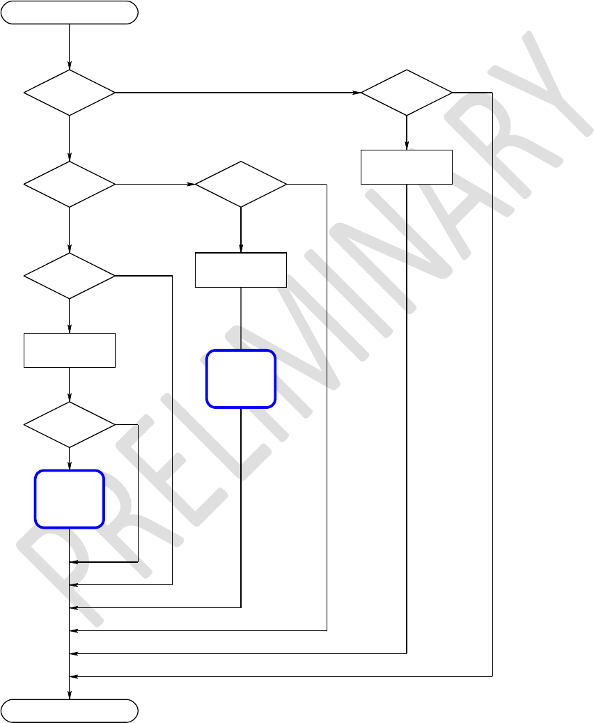
Enhanced Class 1 Bluetooth v2.1 Module
User’s Guide
Americas: +1-800-492-2320 Option 2
Europe: +44-1628-858-940
Hong Kong: +852-2923-0610
www.lairdtech.com/wireless
60
CONN-GUIDE-BT740_v0.2
8.7.6 Host Packet Receive Flowchart
As optimal data throughput is the design goal, the format and detail of packets have been constructed
appropriately. It is recommended that the host implement the following flowchart, for rapid servicing and
flow control of packets.
On Packet Receive
Pkt[2] & 0x80
==0
Pkt[1] ==0
Yes (Command)
No (Data)
Yes (Response)
No (Event)
Len >= 5
Len >= 4
Process
DATA
Len > 2
Yes
Yes
Yes
Process
RESPONSE
Process
EVENT
EVT ==
UNKNOWN_CMD
End
Yes
Module will
be ready to
recieve new
command
Module will
be ready to
recieve new
command
Figure 8-1: Host packet receive flowchart

Enhanced Class 1 Bluetooth v2.1 Module
User’s Guide
Americas: +1-800-492-2320 Option 2
Europe: +44-1628-858-940
Hong Kong: +852-2923-0610
www.lairdtech.com/wireless
61
CONN-GUIDE-BT740_v0.2
8.8 Host Command/Responses
This section describes all host commands and confirms in detail what is specified via the
CMD_ID/CNF_ID field of all command and confirm packets.
The description for each command/confirm below is in the form of a command or confirm packet table and
a corresponding response packet table when appropriate.
Each command has a unique CMD_ID value in the range 1 to 63 (0x01 to 0x3F). 0 is reserved and
confirms a CNF_ID in the range 64 to 127 (0x40 to 0x7F).
The actual value of CMD_ID in the Value column is described as [Descriptive_Name] where
“Descriptive_Name” can be found in a ‘C’ header file which can be obtained on request from Laird.
The value of STATUS is similarly defined in a header file which can also be obtained from Laird.
The commands are grouped as:
Informational
Configuration
Connection
Inquiry
Pairing
Miscellaneous
They are described in subsequent sub chapters.
8.9 Information Commands
This group of commands obtain information about the module.
8.9.1 No Operation
This command results in no action other than to convey new FLOW_IN status to the module and get a
response packet with the latest status for the FLOW_OUT bits.
It is expected that a host uses this packet to poll for a change in the flow bits.
Command Packet
Offset
Field
Value
Comments
0
LENGTH
4
Fixed
1
CHANNEL
0
Fixed
2
COMMAND
[CMD_NO_OPERATION]
3
FLOW_IN
??
Runtime value
Response Packet
Offset
Field
Value
Comments
0
LENGTH
5

Enhanced Class 1 Bluetooth v2.1 Module
User’s Guide
Americas: +1-800-492-2320 Option 2
Europe: +44-1628-858-940
Hong Kong: +852-2923-0610
www.lairdtech.com/wireless
62
CONN-GUIDE-BT740_v0.2
Response Packet
Offset
Field
Value
Comments
1
CHANNEL
0
2
COMMAND
[CMD_NO_OPERATION]
3
FLOW_OUT
??
Runtime value
4
STATUS
[OK]
Or [INVALID_LICENSE]
8.9.2 Get Connectable, Discoverable, Security Modes
This command gets the current connectable, discoverable, and security modes.
Command Packet
Offset
Field
Value
Comments
0
LENGTH
4
Fixed
1
CHANNEL
0
Fixed
2
COMMAND
[CMD_GET_MODES]
3
FLOW_IN
??
Runtime value
Response Packet
Offset
Field
Value
Comments
0
LENGTH
8
1
CHANNEL
0
2
COMMAND
[CMD_GET_MODES]
3
FLOW_OUT
??
Runtime value
4
STATUS
OK or
INVALID_LICENSE
5
DISCMODE
0..3
Bit 0: 1 for discoverable mode
Bit 1: 0 for generic, 1 for limited
discovery mode.
Bits 4..7: Future use specifying which
limited inquiry access
code to use.
6
CONNMODE
0..3
Bit 0: 1 for connectable mode
Bit 1: 1 for Auto Accept Channel

Enhanced Class 1 Bluetooth v2.1 Module
User’s Guide
Americas: +1-800-492-2320 Option 2
Europe: +44-1628-858-940
Hong Kong: +852-2923-0610
www.lairdtech.com/wireless
63
CONN-GUIDE-BT740_v0.2
Response Packet
Offset
Field
Value
Comments
7
SECMODE
12..15
12 = SSP +
IO_CAP_NO_INPUT_NO_OUTPUT
13 = SSP + IO_CAP_DISPLAY_YES_NO
14 = SSP + IO_CAP_KEYBOARD_ONLY
15 = SSP + IO_CAP_DISPLAY_ONLY
Note 1: SECMODE is now driven by the Simple Secure Pairing procedure included in and after v.2.1
of the BT specification.
Note 2: For SECMODE, the No I/O Capability option is equivalent to the ‘Just Works’ scenario in SSP.
Note 3: When this module interacts with a pre-2.1 device, it is unconditionally forced into legacy
pairing mode.
Note 4: Laird recommends that the reader become familiar with the SSP concept introduced in all
subsequent version of BT (post v2.1). The best introduction is to Google the phrase Bluetooth
Simple Secure Pairing.
Note 5: Contact Laird for an informal discussion if necessary.
8.9.3 Read Local Bluetooth Address
This command reads the Bluetooth address of the module.
Command Packet
Offset
Field
Value
Comments
0
LENGTH
4
Fixed
1
CHANNEL
0
Fixed
2
COMMAND
[CMD_READ_BLUETOOTH_ADDRESS]
3
FLOW_IN
??
Runtime value
Response Packet
Offset
Field
Value
Comments
0
LENGTH
11
Fixed
1
CHANNEL
0
Fixed
2
COMMAND
[CMD_READ_BLUETOOTH_ADDRE
SS]
3
FLOW_OU
T
??
Runtime value
4
STATUS
[OK]

Enhanced Class 1 Bluetooth v2.1 Module
User’s Guide
Americas: +1-800-492-2320 Option 2
Europe: +44-1628-858-940
Hong Kong: +852-2923-0610
www.lairdtech.com/wireless
64
CONN-GUIDE-BT740_v0.2
5..10
BDADDR[]
Nap[0,1]:Uap[2]:Lap[3,4,5]
Bluetooth address

Enhanced Class 1 Bluetooth v2.1 Module
User’s Guide
Americas: +1-800-492-2320 Option 2
Europe: +44-1628-858-940
Hong Kong: +852-2923-0610
www.lairdtech.com/wireless
65
CONN-GUIDE-BT740_v0.2
8.9.4 Information
This command extracts information from the module, for example version number.
Command Packet
Offset
Field
Value
Comments
0
LENGTH
5
Fixed
1
CHANNEL
0
Fixed
2
COMMAND
[CMD_INFORMATION]
3
FLOW_IN
??
Runtime value
4
INFOTYPE
0..255
Response Packet
Offset
Field
Value
Comments
0
LENGTH
14
Fixed
1
CHANNEL
0
Fixed
2
COMMAND
[CMD_INFORMATION]
3
FLOW_OUT
??
Runtime value
4
STATUS
[OK]
5
INFOTYPE
0..255
Echoed from command
6.13
DATA[8]
As per the table below
The type of information requested is specified by the INFOTYPE parameter, as per the table below.
INFOTYPE = GET_VERSION (0)
Offset
Field Name
Range
Comments
0
Format/Firmware/Platform
ID
0..255
Bit 7: 1 Bit654: Spare
Bit3210: Firmware/Platform ID
1
STACK_MAJOR
0..255
CCL Version number index
2
APP_MAJOR
0..255
Laird Application Version number
index
3
DEVELOPER/BRANCH ID
0..255
Bit7654: Developer ID
Bit3210: Branch ID
4..5
MSB/LSB of BUILD
NUBMER
0..65535
Odd number == engineering
Even Number == production
6
Reserved
0..255
Laird private use

Enhanced Class 1 Bluetooth v2.1 Module
User’s Guide
Americas: +1-800-492-2320 Option 2
Europe: +44-1628-858-940
Hong Kong: +852-2923-0610
www.lairdtech.com/wireless
66
CONN-GUIDE-BT740_v0.2
INFOTYPE = GET_VERSION (0)
Offset
Field Name
Range
Comments
7
TWIG number/SDK ID
0..255
B7654321 : Twig number
B1 : Laird private use
INFOTYPE = GET_MANUFACTURER (1)
Offset
Field Name
Range
Comments
0..7
Manufacturer/Stack
information
E.g.
“CSR/CCL”
Chip manufacturer, null terminated
string
INFOTYPE = GET_CHIP_INFO (2)
Offset
Field Name
Range
Comments
0..7
Chip
Designation
E.g. “BC4-EXT”
Chip designation, null terminated string
INFOTYPE = GET_PHYSICAL_MEDIUM (3)
Offset
Field Name
Range
Comments
0
Physical Medium
0
0=Bluetooth
1..7
Reserved
0
INFOTYPE = GET_HARDWARE_PLATFORMID (100, 0x64)
Offset
Field Name
Range
Comments
0
Hardware ID (msb)
0..255
1
Hardware ID (lsb)
0..255
2..7
Unused, set to 0’s
Hardware ID is 0x0100 for the BTM4xx series module.
INFOTYPE = MEMORY POOLS (224..239 0xE0..0xEF)
Offset
Field Name
Range
Comments
0..1
Pool Block Size
E.g. 0004
Size of block
2..3
Available Blocks
E.g. 1234
Available and free to use
INFOTYPE = CCL STACK TRUNK VERSION (240 0xF0)
Offset
Field Name
Range
Comments
6..7
Stack Trunk Version
E.g. 1234
Trunk Version of CCL stack

Enhanced Class 1 Bluetooth v2.1 Module
User’s Guide
Americas: +1-800-492-2320 Option 2
Europe: +44-1628-858-940
Hong Kong: +852-2923-0610
www.lairdtech.com/wireless
67
CONN-GUIDE-BT740_v0.2
INFOTYPE = CCL STACK BRANCH VERSION (241 0xF1)
Offset
Field Name
Range
Comments
6..7
Stack Branch Version
E.g. 1234
Branch Version of CCL stack
INFOTYPE = CCL STACK VENA VERSION (248 0xF8)
Offset
Field Name
Range
Comments
6..7
Stack VENA Version
E.g. 1234
VENA Version of CCL stack
8.10 Configuration Commands
This group of commands configures the module.
8.10.1 Read ‘S’ Register
Configure the module using 32 bit integer values, which can be stored in non-volatile memory.
Valid register numbers are in the range 0 to 255.
See the S Registers section for a full list of all registers.
The following command reads the current value of the S register REGNO.
Command Packet
Offset
Field
Value
Comments
0
LENGTH
5
Fixed
1
CHANNEL
0
Fixed
2
COMMAND
[CMD_READ_SREG]
3
FLOW_IN
??
Runtime value
4
REGNO
0 to 255
Response Packet
Offset
Field
Value
Comments
0
LENGTH
10
Fixed
1
CHANNEL
0
Fixed
2
COMMAND
[CMD_READ_SREG]
3
FLOW_OUT
??
Runtime value
4
STATUS
As appropriate
5
REGNO
0 to 255
Echoed from Command

Enhanced Class 1 Bluetooth v2.1 Module
User’s Guide
Americas: +1-800-492-2320 Option 2
Europe: +44-1628-858-940
Hong Kong: +852-2923-0610
www.lairdtech.com/wireless
68
CONN-GUIDE-BT740_v0.2
Response Packet
Offset
Field
Value
Comments
6..9
REGVAL[]
Register Value
REGVAL[0] is the most
significant octet.
8.10.2 Write ‘S’ Register
This command writes a new value to the S register REGNO.
See the S Registers section for a full list of all registers.
Command Packet
Offset
Field
Value
Comments
0
LENGTH
9
Fixed
1
CHANNEL
0
Fixed
2
COMMAND
[CMD_WRITE_SREG]
3
FLOW_IN
??
Runtime value
4
REGNO
0 to 255
5..8
REGVAL[]
New Register Value
REGVAL[0] is the most significant octet.
Response Packet
Offset
Field
Value
Comments
0
LENGTH
10
1
CHANNEL
0
2
COMMAND
[CMD_WRITE_SREG]
3
FLOW_OUT
??
Runtime value
4
STATUS
As appropriate
5
REGNO
0 to 255
Echoed from Command
6..9
REGVAL[]
Register Value
REGVAL[0] is the most significant octet.
8.10.3 Store ‘S’ Registers
This command saves the current ‘S’ register values in cache into the non-volatile memory so that they
survive a power cycle.
Command Packet
Offset
Field
Value
Comments
0
LENGTH
4
Fixed
1
CHANNEL
0
Fixed
2
COMMAND
[CMD_STORE_SREG]
3
FLOW_IN
??
Runtime value

Enhanced Class 1 Bluetooth v2.1 Module
User’s Guide
Americas: +1-800-492-2320 Option 2
Europe: +44-1628-858-940
Hong Kong: +852-2923-0610
www.lairdtech.com/wireless
69
CONN-GUIDE-BT740_v0.2
Response Packet
Offset
Field
Value
Comments
0
LENGTH
5
Fixed
1
CHANNEL
0
Fixed
2
COMMAND
[CMD_STORE_SREG_]
3
FLOW_OUT
??
Runtime value
4
STATUS
As appropriate
8.10.4 Default ‘S’ Registers
This command forces all S register values in cache to factory defaults.
Command Packet
Offset
Field
Value
Comments
0
LENGTH
4
Fixed
1
CHANNEL
0
Fixed
2
COMMAND
[CMD_ DEFAULT_SREG]
3
FLOW_IN
??
Runtime value
Response Packet
Offset
Field
Value
Comments
0
LENGTH
5
Fixed
1
CHANNEL
0
Fixed
2
COMMAND
[CMD_ DEFAULT_SREG_]
3
FLOW_OUT
??
Runtime value
4
STATUS
As appropriate
8.11 Connection Commands
This group of commands manages connections.
8.11.1 Set Connectable Mode
This command enables/disables connectable mode and specifies auto accept parameters for channels
and muxs.
Command Packet
Offset
Field
Value
Comments
0
LENGTH
6
Fixed
1
CHANNEL
0
Fixed
2
COMMAND
[CMD_
CONNECTABLE_MODE]

Enhanced Class 1 Bluetooth v2.1 Module
User’s Guide
Americas: +1-800-492-2320 Option 2
Europe: +44-1628-858-940
Hong Kong: +852-2923-0610
www.lairdtech.com/wireless
70
CONN-GUIDE-BT740_v0.2
Command Packet
Offset
Field
Value
Comments
3
FLOW_IN
??
Runtime value
4
ENABLE
0..1, 0xFF
0 = Disable, 1=Enable
0xFF = Read current mode
5
ACCEPT
Bit mask
Bit 0: Set to auto accept channel
setup
Bit 1..7: Reserved for future use
If bit 0 is set then it overrides SReg
14
otherwise that S Register is
consulted
or incoming connections.
Response Packet
Offset
Field
Value
Comments
0
LENGTH
6
Fixed
1
CHANNEL
0
Fixed
2
COMMAND
[CMD_
CONNECTABLE_MODE]
3
FLOW_OUT
??
Runtime value
4
STATUS
As appropriate
5
CURMODE
0..1
0 = Not connectable
1 = Connectable
8.11.2 Service Incoming Connection
When the module is in connectable mode, incoming connection requests pass to the host via an
EVT_CONNECTION_SETUP message – if and only if autoaccept is not enabled (via command or S
register 14). The host accepts or rejects the remote connection request using this message.
Command Packet
Offset
Field
Value
Comments
0
LENGTH
12
Fixed
1
CHANNEL
0
Fixed
2
COMMAND
[CMD_
CONNECTION_SETUP]
3
FLOW_IN
??
Runtime value
4..9
BDADDR[]
Nap[0,1]:Uap[2]:Lap[3,4,5]
Bluetooth addr
10
HANDLE
0..255
Can be any value the host
wants to set.
This value is echoed by the
module in the response.
11
ACCEPT
0..1
0 = reject. 1..255 = accept
Response Packet
Offset
Field
Value
Comments
0
LENGTH
6
Fixed
1
CHANNEL
0
Fixed
2
COMMAND
[CMD_
CONNECTION_SETUP]
3
FLOW_OUT
??
Runtime value
4
STATUS
As appropriate
5
HANDLE
0..255
Echoed from the command
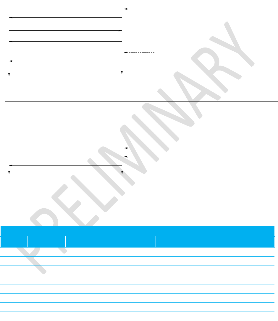
Enhanced Class 1 Bluetooth v2.1 Module
User’s Guide
Americas: +1-800-492-2320 Option 2
Europe: +44-1628-858-940
Hong Kong: +852-2923-0610
www.lairdtech.com/wireless
71
CONN-GUIDE-BT740_v0.2
Receipt of the response is not an indication that the connection has established. If the connection is to be
accepted, the module sends EVT_INCOMING_CONNECTION when the connection is fully established,
as shown in the message sequence chart below.
HOST MODULE
RSP_CONNECTION_SETUP (handle)
CMD_CONNECTION_SETUP (bdaddr,accept,handle)
EVT_CONNECTION_SETUP (bdaddr)
Connection Established
Incoming connection
EVT_INCOMING_CONNECTION
(channelid, bdaddr, uuid)
Figure 8-2: Service Incoming Connection sequence diagram
Note: If auto accept was specified when the module was put into connectable mode, then for
incoming connections there is only an EVT_INCOMING_CONNECTION message.
Connection Established
EVT_INCOMING_CONNECTION
(channelid, bdaddr, uuid)
Incoming connection
HOST MODULE
Figure 8-3: Service Incoming Connection with auto accept specified
8.11.3 Make Outgoing Connection
This command makes an outgoing connection to a profile in the remote peer.
Command Packet
Offset
Field
Value
Comments
0
LENGTH
13
Fixed
1
CHANNEL
0
Fixed
2
COMMAND
[CMD_ MAKE_CONNECTION]
3
FLOW_IN
??
Runtime value
4
HANDLE
0..255
Can be any value the host
wants to set.
This value is echoed by the module in the
response.
5..10
BDADDR[]
Nap[0,1]:Uap[2]:Lap[3,4,5]
Bluetooth address
11..12
UUID[]
0x1101(SPP)
0x1124(HID)
Uuid of the profile to connect to. Offset 11
is the MSB.
13
RFU
0
Always set to zero
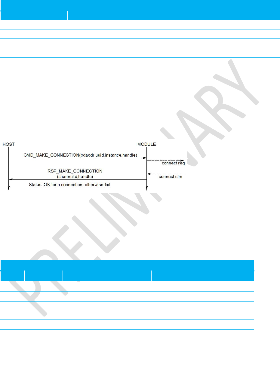
Enhanced Class 1 Bluetooth v2.1 Module
User’s Guide
Americas: +1-800-492-2320 Option 2
Europe: +44-1628-858-940
Hong Kong: +852-2923-0610
www.lairdtech.com/wireless
72
CONN-GUIDE-BT740_v0.2
Response Packet
Offset
Field
Value
Comments
0
LENGTH
7
Fixed
1
CHANNEL
0
Fixed
2
COMMAND
[CMD_
MAKE_CONNECTION]
3
FLOW_OUT
??
Runtime value
4
STATUS
As appropriate
5
HANDLE
0..255
Echoed from the command
6
CHANNEL
1..7 (SPP)
0x20,0x9x,0xA0 (HID
DEVICE)
Channel ID to be used for subsequent SPP
data packets, and also when dropping the
connection
If the STATUS field in the response is MPSTATUS_OK, then a connection successfully established. Any
other value is a failure.
The content of ‘S’ register 11 specifies the max frame size to be used by the lower layers.
Figure 8-4: Make Outgoing Connection sequence diagram
When at least one connection is active (regardless of profile), the DCD output pin asserts.
8.11.4 Drop Connection
This command destroys an existing channel.
Command Packet
Offset
Field
Value
Comments
0
LENGTH
6
Fixed
1
CHANNEL
0
Fixed
2
COMMAND
[CMD_
DROP_CONNECTION]
3
FLOW_IN
??
Runtime value
4
HANDLE
0..255
Can be any value the host
wants to set.
This value is echoed by the module
in the response.
5
CHANNEL
1..7, As appropriate for other
profiles
As was specified in either
RSP_MAKE_CONNECTION or
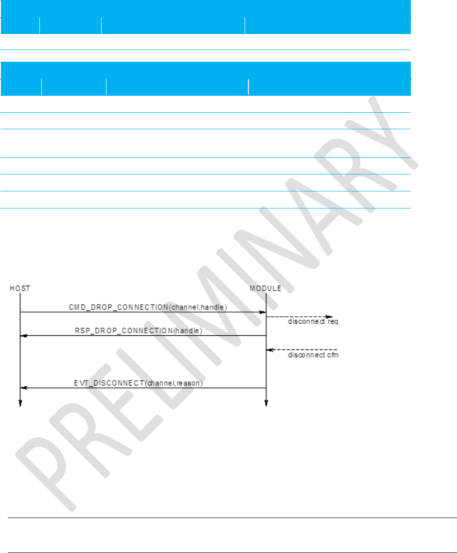
Enhanced Class 1 Bluetooth v2.1 Module
User’s Guide
Americas: +1-800-492-2320 Option 2
Europe: +44-1628-858-940
Hong Kong: +852-2923-0610
www.lairdtech.com/wireless
73
CONN-GUIDE-BT740_v0.2
Command Packet
Offset
Field
Value
Comments
EVT_INCOMMING_CONNECTION
Response Packet
Offset
Field
Value
Comments
0
LENGTH
Fixed
1
CHANNEL
0
Fixed
2
COMMAND
[CMD_
DROP_CONNECTION]
3
FLOW_OUT
??
Runtime value
4
STATUS
As appropriate
5
HANDLE
0..255
Echoed from the command
If the STATUS field in the response is MPSTATUS_OK, then the request to drop the channel successfully
submitted to the lower layers of the stack.
When the channel drops, an EVT_DISCONNECT event sends to the host.
When at least one connection is active (regardless of profile) the DCD output pin remains asserted.
Figure 8-5: Drop Connection sequence diagram
8.12 Set Modem Lines
Bluetooth Serial Port Profile is capable of exchanging modem signals DTR, DSR, RTS, CTS, DCD, and
RI over air.
From a host’s perspective, it can have DTR, RTS, DCD and RI as output lines.
Note: DCD and RI are outputs for modems and ‘host’ in this context can mean either a PC or a
peripheral like a modem.
Additionally UARTs are capable of sending BREAK signals. BREAK output signals are non-idle state TX
pins for a period much greater than the character width at the current baud rate setting.

Enhanced Class 1 Bluetooth v2.1 Module
User’s Guide
Americas: +1-800-492-2320 Option 2
Europe: +44-1628-858-940
Hong Kong: +852-2923-0610
www.lairdtech.com/wireless
74
CONN-GUIDE-BT740_v0.2
This command sends DTR, RTS, DCD, and RI states to the peer device and also to specify a BREAK –
Future Feature.
Command Packet
Offset
Field
Value
Comments
0
LENGTH
7
Fixed
1
CHANNEL
0
Fixed
2
COMMAND
[CMD_
CONTROLMODEMLINES]
3
FLOW_IN
??
Runtime value
4
CHANNEL
1..7
Channel ID of an open channel
5
MODEM
Bit Mask
Bit 0: DTR state
Bit 1: RTS state
Bit 2: DCD state
Bit 3: RI state
Bits 4 .. 7 : Ignored
6
BREAK
0
Not Available
Response Packet
Offset
Field
Value
Comments
0
LENGTH
6
Fixed
1
CHANNEL
0
Fixed
2
COMMAND
[CMD_
CONTROLMODEMLINES]
3
FLOW_OUT
??
Runtime value
4
STATUS
As appropriate
5
CHANNEL
1..7
Echoed from command
The STATUS value is MPSTATUS_OK if the message succeeded.
Modem signals sent by the peer device present to the host in the message EVT_MODEM_STATUS
defined in subsequent chapters.
Note: BREAK signal capability is currently not provided by the lower stack, and so it is mentioned in
the context of this command message for future implementation.
8.12.1 RSSI and Link Quality
This command obtains the RSSI and Link Quality values for a given open connection. This is a parameter
associated with the ACL connection to a peer device and does not have any meaning with channel IDs.
Command Packet
Offset
Field
Value
Comments
0
LENGTH
10
Fixed
1
CHANNEL
0
Fixed

Enhanced Class 1 Bluetooth v2.1 Module
User’s Guide
Americas: +1-800-492-2320 Option 2
Europe: +44-1628-858-940
Hong Kong: +852-2923-0610
www.lairdtech.com/wireless
75
CONN-GUIDE-BT740_v0.2
Command Packet
Offset
Field
Value
Comments
2
COMMAND
[CMD_RSSI_LINKQUAL]
3
FLOW_IN
??
Runtime value
4..9
BDADDR[]
Nap[0,1]:Uap[2]:Lap[3,4,5]
Bluetooth addr
Response Packet
Offset
Field
Value
Comments
0
LENGTH
Fixed
1
CHANNEL
0
Fixed
2
COMMAND
[CMD_RSSI_LINKQUAL]
3
FLOW_OUT
??
Runtime value
4
STATUS
As appropriate
5..10
BDADDR[]
Nap[0,1]:Uap[2]:Lap[3,4,5]
Bluetooth addr
11
RSSI
-128 to 127
RSSI value. Is zero if the signal is within the
golden range
12
LINKQUAL
0 – 255
The definitions of RSSI and LINKQUAL are paraphrased from the Bluetooth specification as follows:
8.12.1.1 RSSI
This value is the difference between the measured Received Signal Strength Indication (RSSI) and the
limits of the Golden Receive Power Range (see Golden Receive Power Range). Any positive RSSI value
returned by the Host Controller indicates how many dB the RSSI is above the upper limit; any negative
value indicates how many dB the RSSI is below the lower limit. A value of zero indicates that the RSSI is
inside the Golden Receive Power Range.
Note: How accurate the dB values are depends on the Bluetooth hardware. The only requirements for
the hardware are that the Bluetooth device is able to tell whether the RSSI is inside, above or
below the Golden Device Power Range.
8.12.1.2 Golden Receive Power Range
The lower threshold level of the golden receive power range corresponds to a received power between -
56 dBm and 6 dB above the actual sensitivity of the receiver. The upper threshold level is 20 dB above
the lower threshold level to an accuracy of +/- 6 dB.
8.12.1.3 Link Quality
Link_Quality is a value from 0-255, which represents the quality of the link between two Bluetooth devices.
The higher the value, the better the link quality. Each Bluetooth module vendor determines how to
measure the link quality.
In the case of CSR, this value is a measure of BER (Bit Error Rate).

Enhanced Class 1 Bluetooth v2.1 Module
User’s Guide
Americas: +1-800-492-2320 Option 2
Europe: +44-1628-858-940
Hong Kong: +852-2923-0610
www.lairdtech.com/wireless
76
CONN-GUIDE-BT740_v0.2
8.13 Get Open Channel List
This command obtains a list of channel IDs corresponding to connections which are open. It is a good
method of querying the module to see how many Bluetooth connections are established and their
corresponding channel ID numbers.
A host should not need to use this command as it should be keeping track of the following two events and
responses: EVT_DISCONNECT, EVT_CONNECTION_SETUP, RSP_MAKE_CONNECTION.
Command Packet
Offset
Field
Value
Comments
0
LENGTH
10
Fixed
1
CHANNEL
0
Fixed
2
COMMAND
[CMD_CHANNEL_LIST
]
3
FLOW_IN
??
Runtime value
Response Packet
Offset
Field
Value
Comments
0
LENGTH
22
Fixed
1
CHANNEL
0
Fixed
2
COMMAND
[CMD_CHANNEL_LIST]
3
FLOW_OUT
??
Runtime value
4
STATUS
As appropriate
5
Count
0..N
Number of connections which have been
established
6..21
Channel ID
List[16]
Array of 16 bytes
A nonzero value implies a connection
exists and the array element value
identifies the channel ID
8.14 Inquiry Commands
This group of commands performs inquiries and puts the module into discoverable mode.
8.14.1 Inquiry Request
This command performs a Bluetooth inquiry.
Command Packet
Offset
Field
Value
Comments
0
LENGTH
6
Fixed
1
CHANNEL
0
Fixed
2
COMMAND
[CMD_INQUIRY_REQ]

Enhanced Class 1 Bluetooth v2.1 Module
User’s Guide
Americas: +1-800-492-2320 Option 2
Europe: +44-1628-858-940
Hong Kong: +852-2923-0610
www.lairdtech.com/wireless
77
CONN-GUIDE-BT740_v0.2
Command Packet
Offset
Field
Value
Comments
3
FLOW_IN
??
Runtime value
4
MAXRESP
1..255
Maximum number of responses before aborting
the inquiry procedure
5
TIMEOUT
1..120
Time in seconds, before aborting the inquiry
procedure.
6
FLAGS
0..1
Bit 0 : 1 To allow repeat addresses.
Bits 1..6 Reserved for future
Bit 7 : Get Enhanced Inquiry responses
Response Packet
Offset
Field
Value
Comments
0
LENGTH
7
Fixed
1
CHANNEL
0
Fixed
2
COMMAND
[CMD_INQUIRY_REQ]
3
FLOW_OUT
??
Runtime value
4
STATUS
As appropriate
5
TOTAL
??
The total number of inquiry responses that were
received from peers.
6
DUMP
??
The total number of inquiry result events that
were not sent because the transmit buffer of the
module was full. This is a result of the host
deasserting its RTS line.
As a result of this command, as and when peer devices respond with inquiry responses, for each inquiry
response, if bit 7 of the FLAGS field is zero then an event EVT_INQUIRY_RESULT sends to the host. If
bit 7 of FLAGS field is one then, given that enhanced inquiry data has variable length data for any given
response, the entire inquiry response sends via data channel 0xF0 to the host, with format described in
subsections below.
When the number of command-specified inquiry responses are received OR the specified time has
elapsed, the final response is sent to indicate to the host that the inquiry procedure is complete.
If the DUMP field in the response is non-zero, it is indicating that the host is not reading it’s receive buffer
fast enough and is resulting in RTS deasserting towards the module.
FLAGS bit 1-4 in future are to specify a limited access code inquiry.
See message sequence diagram (Figure 8-6) which illustrates that the RSP_INQUIRY_REQ message
terminates the inquiry process.
8.14.2 Enhanced Inquiry Data Packet Format
When enhanced inquiry responses are requested via FLAGS bit 7 being set, each inquiry response sends
to the host in data channel 0xF0 and the packet is formatted as follows:
LL F0 AAAAAAAAAAAA CCCCCC RR EE…….EE
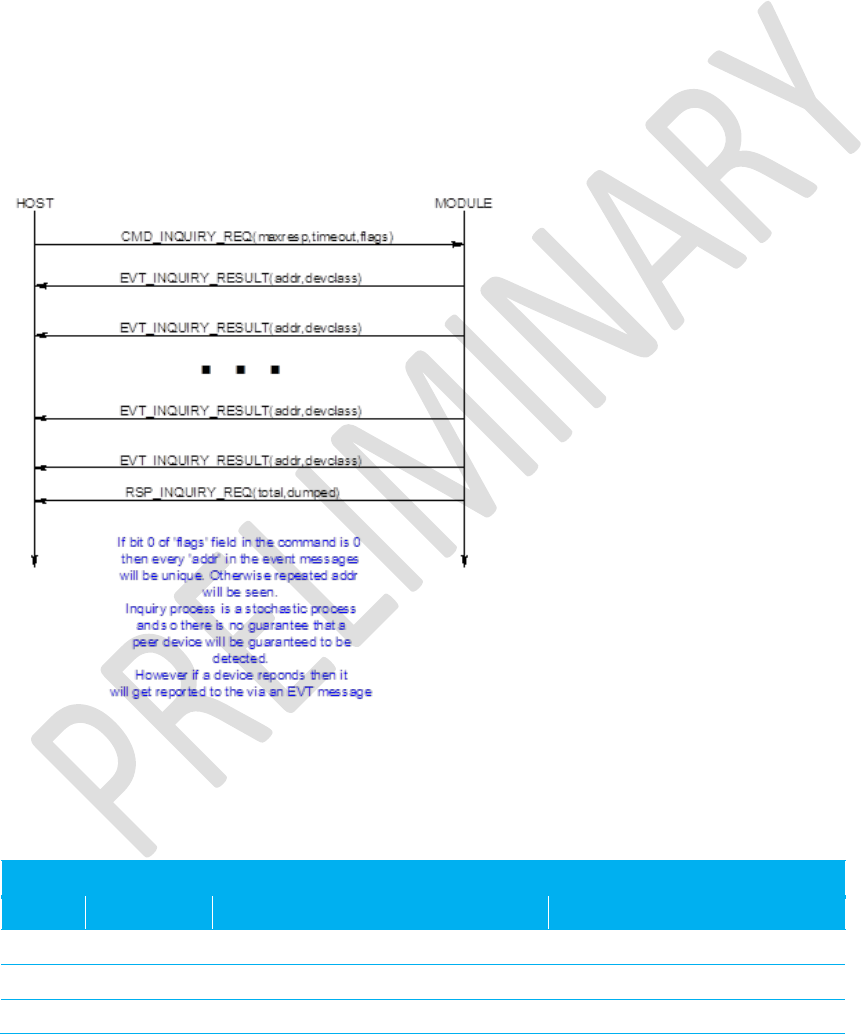
Enhanced Class 1 Bluetooth v2.1 Module
User’s Guide
Americas: +1-800-492-2320 Option 2
Europe: +44-1628-858-940
Hong Kong: +852-2923-0610
www.lairdtech.com/wireless
78
CONN-GUIDE-BT740_v0.2
Where::
LL is the total length of the packet, and given only the EE..EE field is of variable length, the length
of the EE..EE field is calculated by subtracting 12 (decimal) from LL.
F0 is the channel number and is fixed
AAAAAAAAAAAA is a 6 byte field containing the Bluetooth address of the responding device.
CCCCCC is the device class code of the responding device
RR is the measured RSSI value for that response (8 bit signed integer)
EE..EE is a variable length field, with a maximum of 240 bytes, containing the enhanced inquiry
data which is formatted as multiple len/tag/data structures as specified in the Bluetooth
specification. Where both len and tag fields are single bytes and len does not include itself.
Any data passed from the baseband must match the format defined in the Bluetooth Specification Version
2.1 + EDR [1], vol3, Part C – Generic Access Profile, 8 Extended Inquiry Response Data Format (page
1305 in the *.pdf file).
A typical message sequence is as follows:
Figure 8-6: Typical message sequence
8.14.3 Set Discoverable Mode
This command enables/disables discoverable mode.
Command Packet
Offset
Field
Value
Comments
0
LENGTH
5
Fixed
1
CHANNEL
0
Fixed
2
COMMAND
[CMD_ DISCOVERABLE_MODE]

Enhanced Class 1 Bluetooth v2.1 Module
User’s Guide
Americas: +1-800-492-2320 Option 2
Europe: +44-1628-858-940
Hong Kong: +852-2923-0610
www.lairdtech.com/wireless
79
CONN-GUIDE-BT740_v0.2
3
FLOW_IN
??
Runtime value
4
MODE
0..1, 0xFF
0 = Disable,
1 = Generic Access Code
0xFF = Read current mode
Response Packet
Offset
Field
Value
Comments
0
LENGTH
6
Fixed
1
CHANNEL
0
Fixed
2
COMMAND
[CMD_ DISCOVERABLE_MODE]
3
FLOW_OUT
??
Runtime value
4
STATUS
As appropriate
5
CURMODE
0..1
1 = Generic Access Code
The module uses the parameters stored in ‘S’ Registers 7 and 8 to set the inquiry scan interval and
window. Inquiry scan is how often (interval) the radio listens for an inquirer and for how long (window)
each time.
8.15 Pairing Commands
This group of commands manages either incoming or outgoing pairings and the trusted device database
which resides in the non-volatile memory of the module.
The trusted device database is a database with a two tables, each with records of two fields. One field is
the Bluetooth address of a paired device and the other stores the 16 byte link key.
One database is classed a ROLLING database and stores new pairing information as they happen. If the
database is full, then the oldest is discarded to make space for the latest one.
The other database is classed as a PERSISTANT database which stores pairing information which can
ONLY be deleted when a new pairing initiates to that particular device OR on request from the host.
The host protocol provides for a command to transfer a record between these two databases. In addition
there is a command for the host to determine if a device is trusted. There is also a command to manually
insert a device and its link key into the database.
Depending on the peer device, either a legacy pairing procedure or a simple secure pairing occurs. A
legacy pairing occurs if the peer device is older than v2.1 of the Bluetooth specification. Simple Secure
Pairing (for v2.1 and newer devices) uses a Diffie-Hellman procedure to exchange the secret link key, but
is vulnerable to man-in-the-middle attack.
When pairing initiates and a legacy 2.0 or older device is not involved, then the basebands perform an I/O
capability negotiation with each other to see whether it shall perform a ‘Just Works’ unathenticated pairing
with no man-in-the-middle (MITM) protection or an authenticated pairing which requires user interaction.
The I/O capability is one of:
Display Only
Keyboard Only
Display with Yes/No button

Enhanced Class 1 Bluetooth v2.1 Module
User’s Guide
Americas: +1-800-492-2320 Option 2
Europe: +44-1628-858-940
Hong Kong: +852-2923-0610
www.lairdtech.com/wireless
80
CONN-GUIDE-BT740_v0.2
For example:
If one end has Display only, but the other end has keyboard only, then the negotiation results in one end
displaying a six digit passcode on the Display Only side, which is then required to be entered at the
keyboard only end.
If both ends have Display with Yes/No, then during the procedure both ends display a six digit passcode
which needs to be visually compared and then the Yes/No buttons are used to confirm that they match.
This provides for a one in a million probability that a MITM attach is successful.
To enable this new interaction with a user during pairing a new EVT_SIMPLE_PAIRING was defined.
8.15.1 Pair Initiate
This command initiates a pairing with a peer device which is assumed to be ready and waiting for a
pairing. If that device is compliant with v2.0 and older of the Bluetooth specification then a legacy pairing
results and the pincode pin[] in this message is used otherwise there is a simple pairing procedure.
Command Packet
Offset
Field
Value
Comments
0
LENGTH
28
Fixed
1
CHANNEL
0
Fixed
2
COMMAND
[CMD_ PAIR_INITIATE]
3
FLOW_IN
??
Runtime value
4
TIMEOUT
5..120
Pairing timeout in seconds
5..10
BDADDR[]
Nap[0,1]:Uap[2]:Lap[3,4,5]
Bluetooth addr of device to be paired
11..27
PIN[]
17 byte string array
Null Terminated Pin code String. Maximum pin
code length is 16.
Response Packet
Offset
Field
Value
Comments
0
LENGTH
5
Fixed
1
CHANNEL
0
Fixed
2
COMMAND
[CMD_ PAIR_INITIATE]
3
FLOW_OUT
??
Runtime value
4
STATUS
As appropriate
If pairing is successful, the event message EVT_LINK_KEY or EVT_LINK_KEY_EX sends to the host
before the response to close the procedure, as shown in the message sequence chart below.
Pair Initiate may fail if there are any existing open connections. The status byte in the response will have
an appropriate value.
8.15.1.1 Simple Secure Pairing ‘Just Works’
The message sequence diagram for ‘Just Works’ when the device has specified no I/O capability is as
follows:
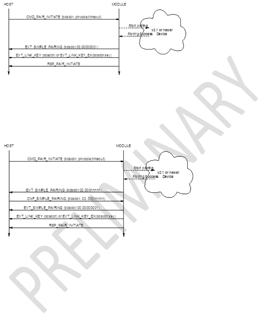
Enhanced Class 1 Bluetooth v2.1 Module
User’s Guide
Americas: +1-800-492-2320 Option 2
Europe: +44-1628-858-940
Hong Kong: +852-2923-0610
www.lairdtech.com/wireless
81
CONN-GUIDE-BT740_v0.2
Figure 8-7: Just Works sequence diagram
The EVT_SIMPLE_PAIRING displays a success/fail indication. If it fails, then the EVT_LINK_KEY event
does not send to the host.
8.15.1.2 Simple Secure Pairing ‘Display Yes/No’
The message sequence diagram for when the device has display and yes/no capability is as follows:
Figure 8-8: Display Yes/No capability sequence diagram
The first EVT_SIMPLE_PAIRING contains a passcode that needs to be confirmed by the host. To confirm
the passcode, the host sends a CNF_SIMPLE_PAIRING packet which has a passcode value of
00000001; to reject it, uses a value of 00000000.
If pairing is successful, another EVT_SIMPLE_PAIRING with a success value is sent and then a
EVT_LINK_KEY event is sent to the host; if not the second EVT_SIMPLE_PAIRING displays a 00000000
value.
8.15.1.1 Simple Secure Pairing ‘Display Only’
The message sequence diagram for when the device has display only capability is as follows:
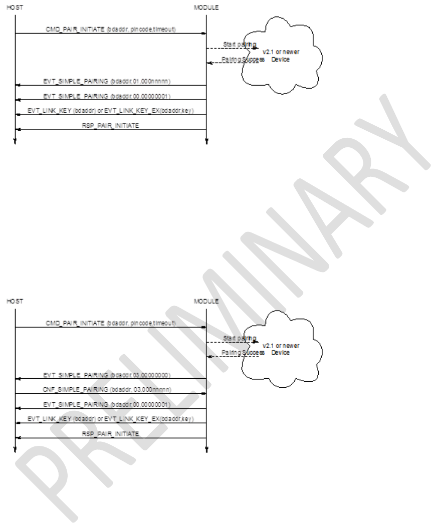
Enhanced Class 1 Bluetooth v2.1 Module
User’s Guide
Americas: +1-800-492-2320 Option 2
Europe: +44-1628-858-940
Hong Kong: +852-2923-0610
www.lairdtech.com/wireless
82
CONN-GUIDE-BT740_v0.2
Figure 8-9: Display Only sequence diagram
The first EVT_SIMPLE_PAIRING contains the passcode which must be displayed. When the peer
confirms the passcode or otherwise, a second EVT_SIMPLE_PAIRING is sent to the host with an
appropriate success/fail code.
If pairing is successful, EVT_LINK_KEY is sent to the host; if not RSP_PAIR_INITIATE indicates a non-ok
status code.
8.15.1.2 Simple Secure Pairing ‘Keyboard Only’
The message sequence diagram for when the device has keyboard only capability is as follows:
Figure 8-10: Keyboard Only sequence diagram
The first EVT_SIMPLE_PAIRING indicates that a simple pairing procedure has started; at that point the
host responds with a confirm packet which contains the passcode that was visually obtained from the
peer device (or both peers decided to use the same code). When the peer confirms the pairing a second
EVT_SIMPLE_PAIRING is sent to the host with an appropriate success/fail code.
If pairing is successful, EVT_LINK_KEY is sent to the host; if not, RSP_PAIR_INITIATE indicates a non-
ok status code.
8.15.2 Incoming Pairing Procedure
As long as the module is in connectable mode (see CMD_CONNECTABLE_MODE) it can accept pairing
from peers.
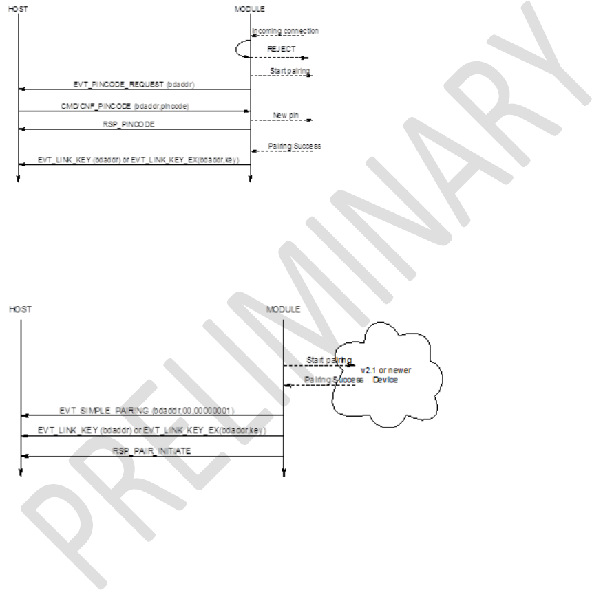
Enhanced Class 1 Bluetooth v2.1 Module
User’s Guide
Americas: +1-800-492-2320 Option 2
Europe: +44-1628-858-940
Hong Kong: +852-2923-0610
www.lairdtech.com/wireless
83
CONN-GUIDE-BT740_v0.2
In that situation, when a pairing procedure is detected, a pincode request event packet is sent to the host
and the host responds with a CMD_PINCODE or CNF_PINCODE command as shown in the message
sequence diagram below (Figure 8-11). It responds with CNF_PINCODE if it is in the middle of making a
connection and a response for ‘make connection’ is still pending.
If the host does not send a pincode command, then the peer that initiated the pairing eventually timeouts.
8.15.1.3 Legacy Pairing
The message sequence diagram for incoming legacy pairing is as follows:
Figure 8-11: Legacy Pairing sequence diagram
8.15.1.4 Simple Secure Pairing ‘Just Works’
The message sequence diagram for ‘Just Works’ when the device has specified no I/O capability is as
follows:
Figure 8-12: Just Works with no I/O capability sequence diagram
The EVT_SIMPLE_PAIRING displays a success indication.
8.15.1.5 Simple Secure Pairing ‘Display Yes/No’
The message sequence diagram for when the device has display and yes/no capability is as follows:
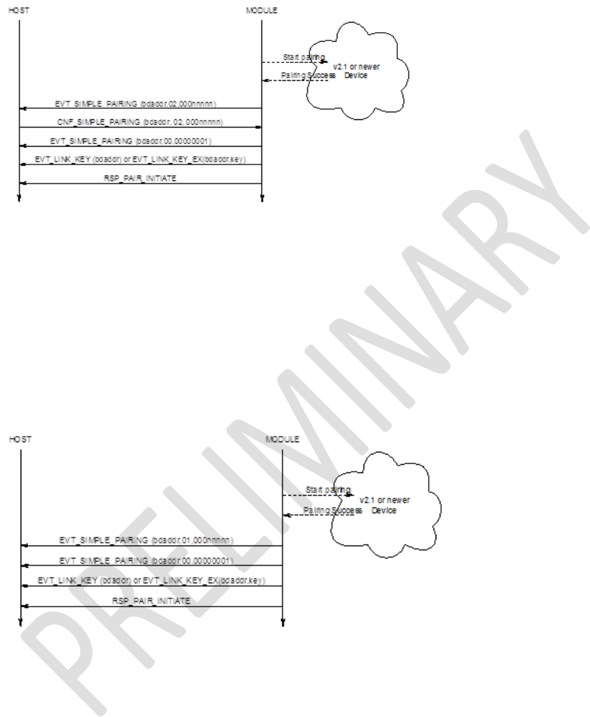
Enhanced Class 1 Bluetooth v2.1 Module
User’s Guide
Americas: +1-800-492-2320 Option 2
Europe: +44-1628-858-940
Hong Kong: +852-2923-0610
www.lairdtech.com/wireless
84
CONN-GUIDE-BT740_v0.2
Figure 8-13: SSP, Display Yes/No sequence diagram
The first EVT_SIMPLE_PAIRING contains a passcode that must be confirmed by the host. To confirm the
passcode, the host sends a CNF_SIMPLE_PAIRING packet which echoes the passcode. To reject it, the
host uses any non-matching value.
If pairing is successful, another EVT_SIMPLE_PAIRING with a success value is sent and then a
EVT_LINK_KEY event is sent to the host, if not the second EVT_SIMPLE_PAIRING displays a 00000000
value.
8.15.1.6 Simple Secure Pairing ‘Display Only’
The message sequence diagram for when the device has display only capability is as follows:
Figure 8-14: SSP, Display Only sequence diagram
The first EVT_SIMPLE_PAIRING contains the passcode which must display. When the peer confirms the
passcode or otherwise a second EVT_SIMPLE_PAIRING is sent to the host with an appropriate
success/fail code.
If pairing is successful, EVT_LINK_KEY is sent to the host; if not RSP_PAIR_INITIATE indicates a non-ok
status code.
8.15.1.7 Simple Secure Pairing ‘Keyboard Only’
The message sequence diagram for when the device has keyboard only capability is as follows:
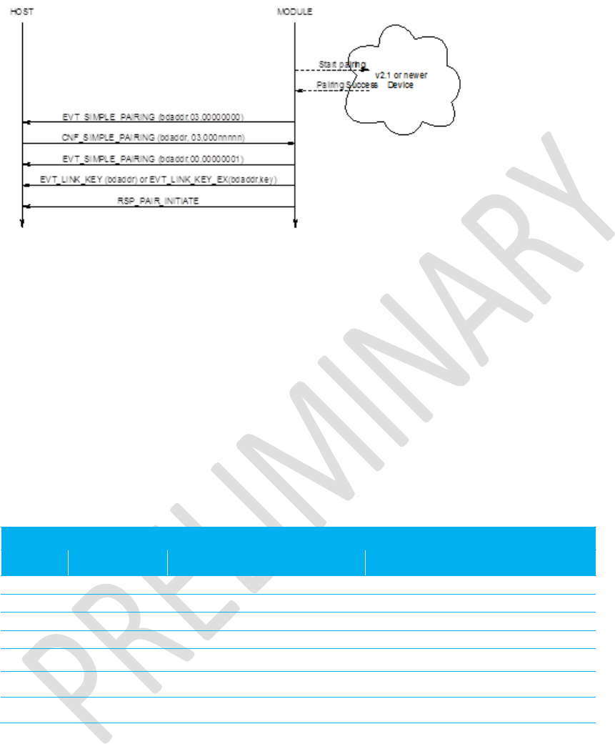
Enhanced Class 1 Bluetooth v2.1 Module
User’s Guide
Americas: +1-800-492-2320 Option 2
Europe: +44-1628-858-940
Hong Kong: +852-2923-0610
www.lairdtech.com/wireless
85
CONN-GUIDE-BT740_v0.2
Figure 8-15: SSP, Keyboard Only sequence diagram
The first EVT_SIMPLE_PAIRING indicates that a simple pairing procedure started and at that point the
host responds with a confirm packet which contains the passcode that was visually obtained from the
peer device (or both peers decided to use the same code). When the peer confirms the pairing, a second
EVT_SIMPLE_PAIRING is sent to the host with an appropriate success/fail code.
If pairing is successful, EVT_LINK_KEY is sent to the host; if not RSP_PAIR_INITIATE indicates a non-ok
status code
8.15.3 SIMPLE PAIRING Confirmation
This confirmation packet provides a response to the module as a result of a EVT_SIMPLE_PAIRING
event and conveys to the module additional information required to complete a simple pairing procedure.
This is a confirmation packet and does not result in a response from the module.
Event Packet
Offset
Field
Value
Comments
0
LENGTH
15
1
CHANNEL
0
2
EVENT
[CNF_ SIMPLE_PAIRING]
3
FLOW_OUT
??
Runtime value
4..9
BDADDR[6]
Nap[0,1]:Uap[2]:Lap[3,4,5]
Bluetooth address of pairing
device
10
action
2..3
See description below
11..14
actionval
4 bytes
See description below
Action :: 0 & 1
This is illegal and is ignored by the module.
Action :: 2
This informs the module the response to a YES/NO query. Set ‘actionval’ to 00000000 for NO and non-
00000000 for YES.
Action :: 3

Enhanced Class 1 Bluetooth v2.1 Module
User’s Guide
Americas: +1-800-492-2320 Option 2
Europe: +44-1628-858-940
Hong Kong: +852-2923-0610
www.lairdtech.com/wireless
86
CONN-GUIDE-BT740_v0.2
This informs the module the response to a passcode query. In this case the ‘actionval’ conveys the
passcode value.
Note: A successful connection to an unpaired 2.1 and newer device requires this confirmation packet
because the MP protocol does not process new commands unless the previous command was
completed by sending an appropriate response packet.
The packet processor in the module queues all commands until a response sends, but processes
confirmation packets as they come.
8.15.4 PinCode (Command)
This command sends a pincode in response to an EVT_PINCODE_REQUEST message and results in a
RSP_PINCODE from the module to the host.
This command can also register a pincode for all subsequent incoming legacy pairings from BT2.0 and
older devices. In that case the BDADDR[] field MUST be set to all zeros.
Command Packet
Offset
Field
Value
Comments
0
LENGTH
28
Fixed
1
CHANNEL
0
Fixed
2
COMMAND
[CMD_PINCODE]
3
FLOW_IN
??
Runtime value
4
TIMEOUT
5..120
Pairing timeout in seconds
5..10
BDADDR[]
Nap[0,1]:Uap[2]:Lap[3,4,5]
Bluetooth address of device requesting the
pairing. Or all zeros to register a pincode for
incoming pairings
11..27
PIN[]
17 byte string array
Null Terminated Pin code String. Maximum pin
code length is 16.
Response Packet
Offset
Field
Value
Comments
0
LENGTH
5
Fixed
1
CHANNEL
0
Fixed
2
COMMAND
[CMD_PINCODE]
3
FLOW_OUT
??
Runtime value
4
STATUS
As appropriate
If pairing is successful the event message EVT_LINK_KEY or EVT_LINK_KEY_EX sends to the host
after the response. The latter event sends if S Register 47 is set to 1.

Enhanced Class 1 Bluetooth v2.1 Module
User’s Guide
Americas: +1-800-492-2320 Option 2
Europe: +44-1628-858-940
Hong Kong: +852-2923-0610
www.lairdtech.com/wireless
87
CONN-GUIDE-BT740_v0.2
8.15.5 PinCode (Confirmation)
This is a confirmation packet which sends a pincode in response to an EVT_PINCODE_REQUEST
message while making an outgoing connection to a legacy pairing device and there was a pairing
challenge by the peer prior to connection acceptance.
This packet, just like the command version of this packet, can also register a pincode for all subsequent
incoming legacy pairings from BT2.0 and older devices. In that case the BDADDR[] field MUST be set to
all zeros.
Command Packet
Offset
Field
Value
Comments
0
LENGTH
28
Fixed
1
CHANNEL
0
Fixed
2
COMMAND
[CNF_PINCODE]
3
FLOW_IN
??
Runtime value
4
TIMEOUT
5..120
Pairing timeout in seconds
5..10
BDADDR[]
Nap[0,1]:Uap[2]:Lap[3,4,5]
Bluetooth address of device requesting the
pairing. Or all zeros to register a pincode for
incoming pairings
11..27
PIN[]
17 byte string array
Null Terminated Pin code String. Maximum
pin code length is 16.
If pairing is successful, the event message EVT_LINK_KEY or EVT_LINK_KEY_EX is sent to the host
after the response. The latter event sends if S Register 47 is set to one.
Note: A successful connection to an unpaired 2.0 and newer device requires this confirmation packet
because the MP protocol does not process new commands unless the previous command was
completed by sending an appropriate response packet.
The packet processor in the module queues all commands until a response sends, but processes
confirmation packets as they come hence in this case CMD_PINCODE does not work.
8.15.6 Trusted Database Record Count
This command obtains the number of trusted devices in the database specified.
Command Packet
Offset
Field
Value
Comments
0
LENGTH
5
Fixed
1
CHANNEL
0
Fixed
2
COMMAND
[CMD_ TRUSTED_DB_COUNT]
3
FLOW_IN
??
Runtime value
4
DBTYPE
0..1
0 = ROLLING DATABASE
1 = PERSISTANT DATABASE

Enhanced Class 1 Bluetooth v2.1 Module
User’s Guide
Americas: +1-800-492-2320 Option 2
Europe: +44-1628-858-940
Hong Kong: +852-2923-0610
www.lairdtech.com/wireless
88
CONN-GUIDE-BT740_v0.2
Response Packet
Offset
Field
Value
Comments
0
LENGTH
8
Fixed
1
CHANNEL
0
Fixed
2
COMMAND
[CMD_
TRUSTED_DB_COUNT]
3
FLOW_OUT
??
Runtime value
4
STATUS
As appropriate
5
DBTYPE
0..1
Echoed from command
6
COUNT
0..N
Number of trusted devices in this
database
7
MAXCOUNT
0..N
Maximum number of devices that can be
stored in this database
Note: ROLLING database stores all new pairings automatically. It is up to the host to transfer a record
from ROLLING to the PERSISTANT database so that it does not get overwritten.

Enhanced Class 1 Bluetooth v2.1 Module
User’s Guide
Americas: +1-800-492-2320 Option 2
Europe: +44-1628-858-940
Hong Kong: +852-2923-0610
www.lairdtech.com/wireless
89
CONN-GUIDE-BT740_v0.2
8.15.7 Trusted Database Read Record
This command reads the Bluetooth address of the ITEMNO pairing in the database specified, counted
from the top. ITEMNO is indexed from one.
Command Packet
Offset
Field
Value
Comments
0
LENGTH
6
Fixed
1
CHANNEL
0
Fixed
2
COMMAND
[CMD_TRUSTED_DB_READ]
3
FLOW_IN
??
Runtime value
4
DBTYPE
0..1
0 = ROLLING DATABASE
1 = PERSISTANT
DATABASE
5
ITEMNO
1..N
Item number to read
Response Packet
Offset
Field
Value
Comments
0
LENGTH
13
Fixed
1
CHANNEL
0
Fixed
2
COMMAND
[CMD_TRUSTED_DB_READ]
3
FLOW_OUT
??
Runtime value
4
STATUS
As appropriate
5
DBTYPE
0..1
Echoed from command
6
ITEMNO
1..N
Echoed from command
7..12
BDADDR[]
Nap[0,1]:Uap[2]:Lap[3,4,5]
Bluetooth addr is all zeros if
the item specified does not
exist
If S Reg 47 is set to one, then it is possible to read a record so that both the address and link key
information is supplied by sending the command CMD_ TRUSTED_DB_ISTRUSTED. In that case, the
event EVT_LINK_KEY_EX is sent before the response to CMD_TRUSTED_DB_ISTRUSTED.
8.15.8 Trusted Database Delete Record
This command deletes a pairing from the databases. It is not necessary to specify the database type, as
both databases are scanned.
Command Packet
Offset
Field
Value
Comments
0
LENGTH
10
Fixed
1
CHANNEL
0
Fixed
2
COMMAND
[CMD_ TRUSTED_DB_DELETE]

Enhanced Class 1 Bluetooth v2.1 Module
User’s Guide
Americas: +1-800-492-2320 Option 2
Europe: +44-1628-858-940
Hong Kong: +852-2923-0610
www.lairdtech.com/wireless
90
CONN-GUIDE-BT740_v0.2
Command Packet
Offset
Field
Value
Comments
3
FLOW_IN
??
Runtime value
4..9
BDADDR[]
Nap[0,1]:Uap[2]:Lap[3,4,5]
Bluetooth addr of device to be
unpaired
Response Packet
Offset
Field
Value
Comments
0
LENGTH
11
Fixed
1
CHANNEL
0
Fixed
2
COMMAND
[CMD_ TRUSTED_DB_DELETE]
3
FLOW_OUT
??
Runtime value
4
STATUS
As appropriate
5..10
BDADDR[]
Nap[0,1]:Uap[2]:Lap[3,4,5]
Bluetooth addr, echoed from
the command
8.15.9 Trusted Database Change Type
This command transfers a record to the database specified.
Command Packet
Offset
Field
Value
Comments
0
LENGTH
11
Fixed
1
CHANNEL
0
Fixed
2
COMMAND
[CMD_TRUSTED_DB_CHANGETYPE]
3
FLOW_IN
??
Runtime value
4
DBTYPE
0..1
5..10
BDADDR[]
Nap[0,1]:Uap[2]:Lap[3,4,5]
Bluetooth addr
Response Packet
Offset
Field
Value
Comments
0
LENGTH
12
Fixed
1
CHANNEL
0
Fixed
2
COMMAND
[CMD_TRUSTED_DB_CHANGETYPE]
3
FLOW_OUT
??
Runtime value
4
STATUS
As appropriate
5
DBTYPE
0..1
Echoed from command
6..11
BDADDR[]
Nap[0,1]:Uap[2]:Lap[3,4,5]
Bluetooth addr, echoed
from the command

Enhanced Class 1 Bluetooth v2.1 Module
User’s Guide
Americas: +1-800-492-2320 Option 2
Europe: +44-1628-858-940
Hong Kong: +852-2923-0610
www.lairdtech.com/wireless
91
CONN-GUIDE-BT740_v0.2
8.15.10 Trusted Database Is Peer Trusted
This command checks if a device is trusted.
Command Packet
Offset
Field
Value
Comments
0
LENGTH
10
Fixed
1
CHANNEL
0
Fixed
2
COMMAND
[CMD_
TRUSTED_DB_ISTRUSTED]
3
FLOW_IN
??
Runtime value
4..9
BDADDR[]
Nap[0,1]:Uap[2]:Lap[3,4,5]
Bluetooth addr
Response Packet
Offset
Field
Value
Comments
0
LENGTH
11
Fixed
1
CHANNEL
0
Fixed
2
COMMAND
[CMD_
TRUSTED_DB_ISTRUSTED]
3
FLOW_OUT
??
Runtime value
4
STATUS
As appropriate
5..10
BDADDR[]
Nap[0,1]:Uap[2]:Lap[3,4,5]
Bluetooth addr, echoed from
the command
The STATUS value is MPSTATUS_OK if the device is trusted; any other value means not trusted.
If S Reg 47 is set to one, then if the peer device is found in the trusted device database, then the event
EVT_LINK_KEY_EX is sent to the host BEFORE the response. That event contains the address and link
key associated with that address.
8.15.11 Trusted Database Add Key (Out-Of-Band Facilitator)
This command manually adds a link key/address pair into the rolling trusted database.
The module does not care how the key was generated and the only validation it performs is to check that
it is 16 bytes long.
Command Packet
Offset
Field
Value
Comments
0
LENGTH
1E
Fixed
1
CHANNEL
0
Fixed
2
COMMAND
[CMD_ TRUSTED_DB_ADD]
3
FLOW_IN
??
Runtime value
4..9
BDADDR[6]
Nap[0,1]:Uap[2]:Lap[3,4,5]
Bluetooth addr

Enhanced Class 1 Bluetooth v2.1 Module
User’s Guide
Americas: +1-800-492-2320 Option 2
Europe: +44-1628-858-940
Hong Kong: +852-2923-0610
www.lairdtech.com/wireless
92
CONN-GUIDE-BT740_v0.2
Command Packet
Offset
Field
Value
Comments
10..25
KEY[16]
16 byte Link Key
Any random value
26..29
FLAGS[4]
00 00 00 00
For future use and MUST be
set to 00000000
Response Packet
Offset
Field
Value
Comments
0
LENGTH
11
Fixed
1
CHANNEL
0
Fixed
2
COMMAND
[CMD_ TRUSTED_DB_ADD]
3
FLOW_OUT
??
Runtime value
4
STATUS
As appropriate
The STATUS value is MPSTATUS_OK if the device was successfully added to the database.
If the device Bluetooth address is already in the trusted device database, then the old one is deleted and
is replaced by this new one.
8.16 Miscellaneous Commands
8.16.1 Get Security Mode
This command gets the current security mode of the module. Bluetooth v2.1 and newer devices cannot
disable security therefore only values 12 to 15 inclusive are valid. These values specify Simple Secure
Pairing with appropriate I/O capabilities.
Specifying a value of 0xFF means leave the mode as it is, but inform the host with regards to current
mode.
Command Packet
Offset
Field
Value
Comments
0
LENGTH
5
Fixed
1
CHANNEL
0
Fixed
2
COMMAND
[CMD_SECURITY_MODE]
3
FLOW_IN
??
Runtime value
4
SECMODE
0xFF
0xFF = Get current mode
Response Packet
Offset
Field
Value
Comments
0
LENGTH
6
Fixed
1
CHANNEL
0
Fixed

Enhanced Class 1 Bluetooth v2.1 Module
User’s Guide
Americas: +1-800-492-2320 Option 2
Europe: +44-1628-858-940
Hong Kong: +852-2923-0610
www.lairdtech.com/wireless
93
CONN-GUIDE-BT740_v0.2
Response Packet
Offset
Field
Value
Comments
2
COMMAND
[CMD_SECURITY_MODE]
3
FLOW_OUT
??
Runtime value
4
STATUS
As appropriate
5
SECMODE
12..15
Current mode
12 = SSP with no input no
output
13 = SSP with yes/no display
14 = SSP with keyboard only
15 = SSP with Display only
1. SECMODE is now driven by the ‘Simple Secure Pairing’ procedure which got included in and after v2.1 of the Bluetooth
specification
2. For ‘SECMODE’ the ‘No I/O capability’ option is equivalent to ‘Just works’ scenario in Simple Secure pairing.
3. When this module interacts with a pre 2.1 device it is unconditionally forced into legacy pairing mode.
4. The reader should become familiar with the ‘Simple Secure Pairing’ concept introduced in and all subsequent version of
Bluetooth after v2.1. The best introduction is to Google the phrase “Bluetooth Simple Secure Pairing”.
5. The reader is also welcome to contact Laird for an informal discussion.
8.16.2 Get Remote Friendly Name
This command gets the friendly name of the specified peer device.
According to the Bluetooth specification, a friendly name can be up to 248 bytes long. Sending this name
in its entirety to the host could violate the max packet length capability of the host because memory
restrictions in the host or transmit buffers in the module may not be able to cope. Therefore, the
mechanism for getting the name to the host is via multiple event packets is EVT_REM_FNAME. The host
decides how many bytes of the name are passed up to it via these events from the offset it also specifies.
This implies that in a memory constraint environment, it is possible to relay the name to the host using
multiple commands.
For example, if the host has space for only 10 bytes and a peer happens to have a very long name, the
host can ask for 10 byte fragments of the name over multiple get name requests.
Command Packet
Offset
Field
Value
Comments
0
LENGTH
13
Fixed
1
CHANNEL
0
Fixed
2
COMMAND
[CMD_GET_REM_FNAME]
3
FLOW_IN
??
Runtime value
4..9
BDADDR[]
Nap[0,1]:Uap[2]:Lap[3,4,5]
Bluetooth addr
10
TIMEOUT
2..120
Timeout in seconds
11
START
N
Offset into the friendly name
string
12
MAXBYTES
M
Maximum number of

Enhanced Class 1 Bluetooth v2.1 Module
User’s Guide
Americas: +1-800-492-2320 Option 2
Europe: +44-1628-858-940
Hong Kong: +852-2923-0610
www.lairdtech.com/wireless
94
CONN-GUIDE-BT740_v0.2
characters to read
Response Packet
Offset
Field
Value
Comments
0
LENGTH
8
Fixed
1
CHANNEL
0
Fixed
2
COMMAND
[CMD_GET_REM_FNAME]
3
FLOW_OUT
??
Runtime value
4
STATUS
As appropriate
5
NAMELEN
0..248
Actual size of the friendly
name
6
START
N
Echoed from the command
7
SENTLEN
S
Total number of bytes sent
Note: SENTLEN could be less than MAXBYTES. It can happen if there is no space in the module’s
TX buffer to send events.
HOST MODULE
Req Friendly Name
EVT_REM_FNAME (index=0,len=10,"?????")
CMD_REM_FNAME (bdaddr, timeout, start=0, maxbytes=25)
EVT_REM_FNAME (index=10,len=10,"?????")
EVT_REM_FNAME (index=20,len=5,"?????")
Got Friendly Name (47 bytes)
CMD_REM_FNAME (namelen=47,start=0,sent=25)
CMD_REM_FNAME (bdaddr, timeout, start=25, maxbytes=22)
Req Friendly Name
Got Friendly Name (47 bytes)
EVT_REM_FNAME (index=25,len=10,"?????")
EVT_REM_FNAME (index=35,len=10,"?????")
EVT_REM_FNAME (index=45,len=2,"?????")
CMD_REM_FNAME (namelen=47,start=25,sent=22)
Figure 8-16: Get Remote Friendly Name sequence diagram
8.16.3 Get Local Friendly Name
This command reads the local friendly name which stores in non-volatile memory.
Unlike the remote friendly name where there is no control over the maximum length, the local friendly
name is limited to 31 characters.

Enhanced Class 1 Bluetooth v2.1 Module
User’s Guide
Americas: +1-800-492-2320 Option 2
Europe: +44-1628-858-940
Hong Kong: +852-2923-0610
www.lairdtech.com/wireless
95
CONN-GUIDE-BT740_v0.2
This length may still be too big to send to the host in one packet. Therefore the name sends in a similar
fashion to ‘get friendly name’ described above. However, in this case, the event EVT_LCL_FNAME gets
the name to the host.
Command Packet
Offset
Field
Value
Comments
0
LENGTH
6
Fixed
1
CHANNEL
0
Fixed
2
COMMAND
[CMD_GET_LCL_FNAME]
3
FLOW_IN
??
Runtime value
4
START
n
Offset into the friendly name
string
5
MAXBYTES
m
Maximum number of characters
to read
Response Packet
Offset
Field
Value
Comments
0
LENGTH
Fixed
1
CHANNEL
0
Fixed
2
COMMAND
[CMD_GET_LCL_FNAME]
3
FLOW_OUT
??
Runtime value
4
STATUS
As appropriate
5
NAMELEN
0..31
Actual size of the friendly name
6
START
n
Echoed from the command
7
SENTLEN
S
Total number of bytes sent in
preceding events.
The name string sends to the host in EVT_LCL_FNAME packets. See description of Get Remote Friendly
name
Note: SENTLEN could be less than MAXBYTES. It can happen if there is no space in the module’s
TX buffer to send events.
8.16.4 Set Local Friendly Name
This command sets the local friendly name in non-volatile memory so that it is used after a power up/reset
cycle.
Since the module can cope with large packets, the name sent to the module in a single command packet
as a null terminated string.
Command Packet
Offset
Field
Value
Comments

Enhanced Class 1 Bluetooth v2.1 Module
User’s Guide
Americas: +1-800-492-2320 Option 2
Europe: +44-1628-858-940
Hong Kong: +852-2923-0610
www.lairdtech.com/wireless
96
CONN-GUIDE-BT740_v0.2
Command Packet
Offset
Field
Value
Comments
0
LENGTH
37
Fixed
1
CHANNEL
0
Fixed
2
COMMAND
[CMD_SET_LCL_FNAME]
3
FLOW_IN
??
Runtime value
4
FLAGS
1..2
1 = Write to non-vol store for use on next
power up
2 = Make the name visible now
5
NAMELEN
1..30
6..36
NAME[31]
Null terminated string
Not more than 30 characters
Response Packet
Offset
Field
Value
Comments
0
LENGTH
5
Fixed
1
CHANNEL
0
Fixed
2
COMMAND
[CMD_SET_LCL_FNAME]
3
FLOW_OUT
??
Runtime value
4
STATUS
As appropriate
8.16.5 Set Device Class
This command sets the device class code so that the base band makes it visible immediately. This is
opposed to setting it via S Register 120 which only expedites on power up.
Command Packet
Offset
Field
Value
Comments
0
LENGTH
7
Fixed
1
CHANNEL
0
Fixed
2
COMMAND
[CMD_SET_DEVCLASS]
3
FLOW_IN
??
Runtime value
4..6
DEVCLASS[3]
New 24 bit device class
MSB of device class is at offset 4
Response Packet
Offset
Field
Value
Comments
0
LENGTH
Fixed
1
CHANNEL
0
Fixed
2
COMMAND
[CMD_SET_DEVCLASS]
3
FLOW_OUT
??
Runtime value

Enhanced Class 1 Bluetooth v2.1 Module
User’s Guide
Americas: +1-800-492-2320 Option 2
Europe: +44-1628-858-940
Hong Kong: +852-2923-0610
www.lairdtech.com/wireless
97
CONN-GUIDE-BT740_v0.2
4
STATUS
As appropriate

Enhanced Class 1 Bluetooth v2.1 Module
User’s Guide
Americas: +1-800-492-2320 Option 2
Europe: +44-1628-858-940
Hong Kong: +852-2923-0610
www.lairdtech.com/wireless
98
CONN-GUIDE-BT740_v0.2
8.16.6 Factory Default
This command clears non-volatile memory in the module so that it reverts to factory default state.
The FLAGS field is a bit mask which selectively clears various types of non-volatile memory and should
be set to FF.
Command Packet
Offset
Field
Value
Comments
0
LENGTH
5
Fixed
1
CHANNEL
0
Fixed
2
COMMAND
[CMD_FACTORYDEFAULT]
3
FLOW_IN
??
Runtime value
5
FLAGS
8 bit mask
See notes below
0xFF to delete all groups,
present and future
Response Packet
Offset
Field
Value
Comments
0
LENGTH
Fixed
1
CHANNEL
0
Fixed
2
COMMAND
[CMD_FACTORYDEFAULT]
3
FLOW_OUT
??
Runtime value
4
STATUS
As appropriate
Note: Non-volatile information in the module is divided into various subgroups and the FLAGS bits
allow selective resetting to factory state for those subgroups. The bits are allocated as follows:
Bit 0 : S registers
Bit 1 : Local Friendly Name
Bit 2 : HID Device Descriptos
Bit 3 : Reserved – Always set to 1
Bit 4 : Reserved – Always set to 1
Bit 5 : Reserved – Always set to 1
Bit 6 : Link Keys
Bit 7 : Special S registers (240 to 255 in the multipoint space)

Enhanced Class 1 Bluetooth v2.1 Module
User’s Guide
Americas: +1-800-492-2320 Option 2
Europe: +44-1628-858-940
Hong Kong: +852-2923-0610
www.lairdtech.com/wireless
99
CONN-GUIDE-BT740_v0.2
8.16.7 Get Digital/Analog I/O
This command reads the states of up to 16 digital input lines and optionally requests an analogue input
reading.
This response packet contains two octets containing the digital input states. If an analogue input reading
is requested then the ADC reading is supplied in an EVENT_ADC event.
Command Packet
Offset
Field
Value
Comments
0
LENGTH
6
Fixed
1
CHANNEL
0
Fixed
2
COMMAND
[CMD_GET_IO]
3
FLOW_IN
??
Runtime value
4
digId
0
0 = Digital I/o in Module
5
analogId
0
0 = No ADC access
1..255 = FUTURE USE
See Note 1
Response Packet
Offset
Field
Value
Comments
0
LENGTH
Fixed
1
CHANNEL
0
Fixed
2
COMMAND
[CMD_GET_IO]
3
FLOW_OUT
??
Runtime value
4
STATUS
As appropriate
5
digId
0
Echoed from command packet
6..7
digIn[2]
??
Digital inputs 0 to 15. Bit 15 is
bit 7 in the MSB.
See Note 2
Note 1: If the analogID field in the command is non-zero, and EVENT_ADC generates when the ADC
is read and available.
Note 2: Bit 0 corresponds to GPIO0, Bit 1 corresponds to GPIO1, etc. Refer to the module’s data
sheet to check which GPIO pins are available for use.

Enhanced Class 1 Bluetooth v2.1 Module
User’s Guide
Americas: +1-800-492-2320 Option 2
Europe: +44-1628-858-940
Hong Kong: +852-2923-0610
www.lairdtech.com/wireless
100
CONN-GUIDE-BT740_v0.2
8.16.8 Set Digital I/O
This command controls the states of up to 16 digital output lines.
Command Packet
Offset
Field
Value
Comments
0
LENGTH
6
Fixed
1
CHANNEL
0
Fixed
2
COMMAND
[CMD_SET_IO_EX]
3
FLOW_IN
??
Runtime value
4
ioId
0
0 = Digital I/o in Module
5..6
mask[2]
0000..FFFF
Only set bits are specify which
bits in ioVal submit to the digital
I/O
See Note 1
7..8
ioVal[2]
0000..FFFF
Only the bits set in mask
update at the output
See Note 1
Response Packet
Offset
Field
Value
Comments
0
LENGTH
Fixed
1
CHANNEL
0
Fixed
2
COMMAND
[CMD_SET_IO]
3
FLOW_OUT
??
Runtime value
4
STATUS
As appropriate
1. Bit 0 corresponds to GPIO0, Bit 1 to GPIO1 etc. Please refer to the module’s data sheet to
check which GPIO pins are available for use.
8.16.9 Reset
This command resets the module.
Command Packet
Offset
Field
Value
Comments
0
LENGTH
7
Fixed
1
CHANNEL
0
Fixed
2
COMMAND
[CMD_RESET]
3
FLOW_IN
??
Runtime value
4..6
RESVD[3]
00 00 00
Reserved for future use, set to
zeros.

Enhanced Class 1 Bluetooth v2.1 Module
User’s Guide
Americas: +1-800-492-2320 Option 2
Europe: +44-1628-858-940
Hong Kong: +852-2923-0610
www.lairdtech.com/wireless
101
CONN-GUIDE-BT740_v0.2
There is no response to this command packet. However, on reset there is at least one EVT_STATUS
event so that can be used to detect that the device has rebooted.
8.16.10 BLOB Manage
This command manages binary data uploaded from the host through data channels 0x98 to 0x9F (the
number of BLOB data channels is compile time dependent). The binary data is referred to as a ‘BLOB’
(binary long object).
Command Packet
Offset
Field
Value
Comments
0
LENGTH
14
Fixed
1
CHANNEL
0
Fixed
2
COMMAND
[CMD_BLOBMANAGE]
3
FLOW_IN
??
Runtime value
4
subCmdId
0..9
5
blobId
0..1
Identifies the BLOB that this command acts
on.
Data Channels correspond to (0x98 +
blobID)
6..9
ParmA
Offset 6 is MSB
Offset 9 is LSB
Parameter A
10..13
ParmB
Offset 10 is MSB
Offset 13 is LSB
Parameter B
Response Packet
Offset
Field
Value
Comments
0
LENGTH
15
Fixed
1
CHANNEL
0
Fixed
2
COMMAND
[CMD_ BLOBMANAGE]
3
FLOW_OUT
??
Runtime value
4
STATUS
As appropriate
5
subCmdId
Echoed from command
6
blobId
Echoed from command
7..10
ParmA
Offset 7 is MSB
Offset 10 is LSB
Depends on subCmdId
11..14
ParmB
Offset 11 is MSB
Offset 14 is LSB
Depends on subCmdId
Action to perform

Enhanced Class 1 Bluetooth v2.1 Module
User’s Guide
Americas: +1-800-492-2320 Option 2
Europe: +44-1628-858-940
Hong Kong: +852-2923-0610
www.lairdtech.com/wireless
102
CONN-GUIDE-BT740_v0.2
SubCmdId field specifies the actions that the BLOB manager should take on the BLOB specified in field
blobID and are described in the following sub sections.
Clear :: 0
Use this subcommand to clear the BLOB specified by ‘blobID’, On return ParmA and ParmB are set to
zero.
Get Size :: 1
Use this subcommand to get the number of bytes in the BLOB specified by ‘blobID’, On return ParmA
contains the number and ParmB is set to zero.
Read :: 2
Use this subcommand to transmit the content of the BLOB specified by ‘blobID’. If there is data in the
BLOB then it results in one or more data packets sending to the host on channel (0x98+BlobID).The data
in the BLOB is not destroyed. On return ParmA contains the number of bytes in the BLOB and ParmB
contains the number actually sent in the data packets.
Save Hid Descriptor :: 3
Use this subcommand to first do a basic validation of the data block identified by blobID to see that it
contains a valid HID descriptor and if so, save the data to a non-volatile memory set aside to save an
array of HID descriptors. The index into that array is specified by ParmA which is referred to as the HIDID.
In the response, ParmA contains 0 for success, 1 for invalid HID descriptor, 2 for failed to save to nonvol
array and 000000FF for invalid blobID or invalid HIDID.
Load Hid Descriptor :: 4
Use this subcommand to append the content of the HID descriptor in non-volatile memory identified by a
HIDID which is specified in ParmA into the data object identified by blobID.
In the response, ParmA contains 0 for success, 2 for failed to load from nonvol array and 000000FF for
invalid blobID or invalid HIDID.
After the BLOB loads, use subcommand Read::2 to force the transmission of the HID descriptor to the
host.
Save Custom HID Descriptor Service name :: 5
Use this subcommand to save the service name (Less than 30 characters) that is used when a custom
HID device SDP record is registered (When SReg 39 > 0).
In the response, ParmA contains 0 for success, 1 for invalid service anme, 2 for failed to save to nonvol
array and 000000FF for invalid blobID.
Load Custom HID Descriptor Service name :: 6
Use this subcommand to append the content of the HID service name in non-volatile memory.
In the response, ParmA contains 0 for success, 2 for failed to load from nonvol array and 000000FF for
invalid blobID.
After the BLOB loads, use subcommand Read::2 to force the transmission of the name to the host.
Commit BLOB as Enhanced Inquiry :: 7
Use this subcommand to commit the current content of the BLOB specified as Enhanced Inquiry
Responses. The data validates so that it conforms to the format specified in described in the Bluetooth
Specification Version 2.1 + EDR [1], vol3, Part C – Generic Access Profile, 8 Extended Inquiry Response
Data Format (page 1305 in the .pdf-file).

Enhanced Class 1 Bluetooth v2.1 Module
User’s Guide
Americas: +1-800-492-2320 Option 2
Europe: +44-1628-858-940
Hong Kong: +852-2923-0610
www.lairdtech.com/wireless
103
CONN-GUIDE-BT740_v0.2
The data block consists of one or more objects, where the first byte of each object specifies the length
and the second byte specifies the type of data and the rest of the bytes for that object are the associated
data.
For example, to send the string “HelloWorld” and “LairdRules!” as the manufacturer specific data objects,
then the BLOB should load with the following data :
0B FF ‘H’ ‘e’ ‘l’ ‘l’ ‘o’ ‘W’ ‘o’ ‘r’ ‘l’ ‘d’ 0C FF ‘L’ ‘a’ ‘I’ ‘r’ ‘d’ ‘R’ ‘u’ ‘l’ ‘e’ ‘s’ ‘!’
Where 0B and 0C are length bytes and FF is the type value for ‘manufacturer specific data’.
Before submission, the data block is verified to see if the length bytes are consistent with total length of
the block.
Save Enhanced Inquired Response Data :: 8
Use this subcommand to save the BLOB data in non-volatile memory so that the data installs the custom
EIR data response on every power up. Before committing to memory, the data block is verified to see if
the length bytes are consistent with total length of the block.
Load Enhanced Inquired Response Data:: 9
Use this subcommand to load the BLOB specified with data from non-volatile memory associated with
Enhanced Inquiry responses; The data that was saved using subcommand 8 described.
8.17 HDP Profile Commands
Health Device Profile (HDP) is available on the module in both Agent and Manager roles as defined by
the Continua Alliance (see www.continua.org). The manager role is for testing the agent implementation
only and it is not expected or designed for eventual certification by the Continua Alliance.
It is assumed that the reader is familiar with all the HDP and IEEE documentation and relevant guidelines
published by the Continua Alliance. For further background information related to the HDP
implementation in this module please refer to AT Application Examples.
The HDP commands, responses and events described in the subsequent chapters are merely the MP
way of managing the functionality and do not add any new features other than those described in the AT
Applications Example section. Laird recommends the reader to refer to the AT Application Examples
section for further details.
To assist with this cross referencing of details, the table below shows the equivalent commands in AT and
MP mode respectively to achieve the same effect in the module.
AT Mode Commands
MP Mode Commands
Comments
AT+HAEiiii,”name”
AT+HMEiiii,”name”
CMD_HDP_ENDPOINT
Affects an entry in the SDP record
AT+HAL
AT+HML
CMD_HDP_SDPREGISTER
Register and activate HDP service
record
AT+HABeeeee,iiii
CMD_HDP_BIND
Create an agent data
specialization of type iiii which will
connect to a manager with
Bluetooth address ‘eeeeee’
AT+HAAhhhh
CMD_HDP_ASSOCIATE
AT+HARhhhh,pppp[…]
CMD_HDP_SCANREPORT_FI
XED
CMD_HDP_SCANREPORT_V
AR
In MP, the attribute list for var
report is supplied via a BLOB
channel.
AT+HAGhhhh,aaaa,ssss
CMD_HDP_ATTRIBUTE_REA
Read an attribute value. In MP

Enhanced Class 1 Bluetooth v2.1 Module
User’s Guide
Americas: +1-800-492-2320 Option 2
Europe: +44-1628-858-940
Hong Kong: +852-2923-0610
www.lairdtech.com/wireless
104
CONN-GUIDE-BT740_v0.2
AT Mode Commands
MP Mode Commands
Comments
AT+HMGhhhh,oooo,aaaa
D
mode the data value sends in data
channel B0
AT+HAShhhh,aaaa,ssss,dddd
dd
CMD_HDP_ATTRIBUTE_WRIT
E
Write an attribute value. In MP
mode the data value is taken from
data channel B0
AT+HMThhhh,ttttt
CMD_HDP_SETTIME
Used at manager end to send new
date/time to the agent
AT+HADhhhh
CMD_HDP_DISASSOCIATE
The following table shows the equivalent AT asynchronous responses and MP events.
AT Mode Async
Responses
MP Mode Events
Comments
HDA:DISASSOCIATED
hhhh
HDM:DISASSOCIATED
hhhh
EVT_HDP_DISASSOCIA
TED
Sent to host when the agent disassociates
from the manager or fails to connect to it
HDA:ASSOCIATED hhhh,..
HDM:ASSOCIATED hhhh,..
EVT_HDP_ASSOCIATE
D
HDA:TIME hhhh,ttttt
EVT_HDP_TIMEUPDAT
E
At Agent end only.
Manager informs Agent host of new
date/time.
Manager triggers this using the command
AT+HMD or CMD_HDP_SETTIME
8.17.1 HDP related S Registers
To enable HDP profile, Bit 2 in SReg 3 must be set to one and SReg 70 specifies whether it is an agent
role ( = 0) or a manager role ( = 1 ).
In addition SReg 71 specifies the auto-disassociate timeout in the agent role only, where 0 denotes no
timeout. If this is a non-zero value, then after an association or the triggering of a scan report if no further
activity occurs in that time, then an automatic disassociation initiates.
SReg 72 specifies the maximum transmit PDU size for HDP packets in the underlying Bluetooth transport
layer.
8.17.2 Create Endpoint in SDP Record
This command creates a data specialization source (for agent role) or a sink (for manager role) which
registers using the CMD_HDP_SDPREGISTER command. This SDP entry allows peers to determine
which data specialization the module services.
It is not necessary to specify which role explicitly in the command because S Reg 70 determines whether
the module is configured for an Agent or Manager role. For Agent role SReg 70 is set to 0 and 1 for
Manager.
This command is relevant for both Agent and Manager roles.
Command Packet
Offset
Field
Value
Comments

Enhanced Class 1 Bluetooth v2.1 Module
User’s Guide
Americas: +1-800-492-2320 Option 2
Europe: +44-1628-858-940
Hong Kong: +852-2923-0610
www.lairdtech.com/wireless
105
CONN-GUIDE-BT740_v0.2
0
LENGTH
22
Fixed
1
CHANNEL
0
Fixed
2
COMMAND
[CMD_HDP_ENDPOINT]
3
FLOW_IN
??
Runtime value
4..5
SpecType[2]
As per IEEE spec
[4]=msb,[5]=lsb
Data Specialization code.
For example: 100F (4111 dec) for Weigh Scale
6..21
Name[15+1]
Null Terminated Name
Maximum name size is 15 and name MUST be
terminated by a NULL
Response Packet
Offset
Field
Value
Comments
0
LENGTH
5
Fixed
1
CHANNEL
0
Fixed
2
COMMAND
[CMD_HDP_ENDPOINT]
3
FLOW_OUT
??
Runtime value
4
STATUS
As appropriate
Create multiple data specialization endpoints by submitting this command an appropriate number of times.
Internally in the module, the SpecType[2] and Name[15+1] information caches in heap memory until the
command CMD_HDP_SDPREGISTER transfers that information into the SDP record for final submission
to the underlying Bluetooth stack.
8.17.3 Register SDP record
This command registers and activates an HDP related SDP record after creating the endpoints using
CMD_HDP_ENDPOINT. Only after this is done can incoming HDP connections be serviced.
It is not necessary to specify which role explicitly in the command because S Reg 70 determines whether
the module is configured for an Agent or Manager role. For Agent role SReg 70 is set to 0 and 1 for
Manager.
This command is relevant for both Agent and Manager roles.
Command Packet
Offset
Field
Value
Comments
0
LENGTH
4
Fixed
1
CHANNEL
0
Fixed
2
COMMAND
[CMD_HDP_SDPREGISTER]
3
FLOW_IN
??
Runtime value
Response Packet
Offset
Field
Value
Comments

Enhanced Class 1 Bluetooth v2.1 Module
User’s Guide
Americas: +1-800-492-2320 Option 2
Europe: +44-1628-858-940
Hong Kong: +852-2923-0610
www.lairdtech.com/wireless
106
CONN-GUIDE-BT740_v0.2
0
LENGTH
5
Fixed
1
CHANNEL
0
Fixed
2
COMMAND
[CMD_HDP_SDPPREGISTER]
3
FLOW_OUT
??
Runtime value
4
STATUS
As appropriate
Internally in the module, the SpecType[2] and Name[15+1] information previously cached in heap
memory from CMD_HDPENDPOINT commands transfers into an SDP record and submits to the
underlying stack. After this a peer is able to see this device offering HDP services.
8.17.4 Bind Agent to a Manager
This command binds the Bluetooth address of a manager and an agent data specialization to create an
object within the module which a 16 bit handle can subsequently reference, which returns in the
response if the command successfully accepts.
This command is relevant for Agent role only.
Command Packet
Offset
Field
Value
Comments
0
LENGTH
14
Fixed
1
CHANNEL
0
Fixed
2
COMMAND
[CMD_HDP_BIND]
3
FLOW_IN
??
Runtime value
4..9
BDADDR[]
Nap[0,1]:Uap[2]:La
p[3,4,5]
Bluetooth address
10.11
SpecType[2]
As per IEEE spec
[10]=msb,[11]=lsb
Data Specialization code.
For example: 100F (4111 dec) for Weigh Scale
12.13
AssocTout[2]
[12]=msb,[13]=lsb
Automatic deassociation timeout. 0 = no timeout
Response Packet
Offset
Field
Value
Comments
0
LENGTH
7
Fixed
1
CHANNEL
0
Fixed
2
COMMAND
[CMD_HDP_BIND]
3
FLOW_OUT
??
Runtime value
4
STATUS
As appropriate
5..6
HANDLE[2]
[5]=msb,[6]=lsb
Handle identifying this instance of data
specialization agent
The handle returned in the response, if STATUS equals 0, is subsequently used in many commands. If
the STATUS byte is not 0, then the HANDLE value i 0.

Enhanced Class 1 Bluetooth v2.1 Module
User’s Guide
Americas: +1-800-492-2320 Option 2
Europe: +44-1628-858-940
Hong Kong: +852-2923-0610
www.lairdtech.com/wireless
107
CONN-GUIDE-BT740_v0.2
8.17.5 Associate with Manager
This command associates an agent with a manager, using the pre-defined object created using the
CMD_HDP_BIND command which returns a handle to represent that object.
This command is relevant for Agent role only.
Command Packet
Offset
Field
Value
Comments
0
LENGTH
6
Fixed
1
CHANNEL
0
Fixed
2
COMMAND
[CMD_HDP_ASSOCIATE]
3
FLOW_IN
??
Runtime value
4..5
HANDLE[2]
[4]=msb,[5]=lsb
Handle identifying an instance of
data specialization agent/manager
combination
RESPONSE PACKET
Offset
Field
Value
Comments
0
LENGTH
5
Fixed
1
CHANNEL
0
Fixed
2
COMMAND
[CMD_HDP_ASSOCIATE]
3
FLOW_OUT
??
Runtime value
4
STATUS
As appropriate
The host waits until the response receives before submitting further commands.
If association is successful prior to receiving the response, the host sends EVT_ASSOCIATED, which
contains the config ID of the MDS configuration that was negotiated and the system ID of the peer. See
EVT_ASSOCIATED for further details.
If association was not successful, because for example the manager is not in range or the Bluetooth
device specified in CMD_HDP_BIND does not offer HDP services, then the EVT_DISASSOCIATED
sends to the host prior to the response message. This is shown in the message sequence diagram below.

Enhanced Class 1 Bluetooth v2.1 Module
User’s Guide
Americas: +1-800-492-2320 Option 2
Europe: +44-1628-858-940
Hong Kong: +852-2923-0610
www.lairdtech.com/wireless
108
CONN-GUIDE-BT740_v0.2
CMD_HDP_ASSOCIATE(handle)
EVT_ASSOCIATED(handle,spec,cfgid,sysid)
RSP_HDP_ASSOCIATE(OK)
AgentHost
CMD_HDP_ASSOCIATE(handle)
EVT_DISASSOCIATED(handle)
RSP_HDP_ASSOCIATE(not OK)
AgentHost
Successful
Association
Unsuccessful
Association
Figure 8-17: Associate sequence diagram
8.17.6 Send Fixed Scan Report to Manager
This command associates (if not already associated) and sends a fixed scan report from an agent to the
bound manager. The binding specified via the CMD_HDP_BIND command which returns a handle to
represent that combination object.
This command is relevant for Agent role only, and results in an EVT_HDP_SCANREPORT event at the
manager end.
A fixed report sends the values for a list of attributes to a manager where the list is predefined in the
MDC_ATTR_ATTRIBUTE_VAL_MAP attribute of the NU collection object.
Command Packet
Offset
Field
Value
Comments
0
LENGTH
9
Fixed
1
CHANNEL
0
Fixed
2
COMMAND
[CMD_HDP_SCANREPORT_FIXED]
3
FLOW_IN
??
Runtime value
4..5
HANDLE[2]
[4]=msb,[5]=lsb
Handle identifying an instance
of data specialization
agent/manager combination
6..7
PERSONID[2]
[6]=msb,[7]=lsb
This identifies a person ID
which the manager can uses
appropriately
8
HOSTCONTEXT
XX
This echos back in the
response and helps the host to
keep track of them
Response Packet

Enhanced Class 1 Bluetooth v2.1 Module
User’s Guide
Americas: +1-800-492-2320 Option 2
Europe: +44-1628-858-940
Hong Kong: +852-2923-0610
www.lairdtech.com/wireless
109
CONN-GUIDE-BT740_v0.2
Offset
Field
Value
Comments
0
LENGTH
8
Fixed
1
CHANNEL
0
Fixed
2
COMMAND
[CMD_HDP_SCANREPORT_FIXED]
3
FLOW_OUT
??
Runtime value
4
STATUS
As appropriate
5..6
HANDLE[2]
[4]=msb,[5]=lsb
Echoed back from the command
7
HOSTCONTEXT
XX
This is echoed back from the
command
The host waits until the response receives before submitting further commands.
If the agent is not associated, then this command first results in an association request and if that is
successful the host receives EVT_ASSOCIATED which contains the config ID of the MDS configuration
that was negotiated and the system ID of the peer. See EVT_ASSOCIATED for further details.
If the agent is already associated, then there is a response as soon as there is acknowledgement from
the manager that the scan report was received.
If association was not successful, because for example the manager is not in range or the Bluetooth
device specified in CMD_HDP_BIND does not offer HDP services, then the EVT_DISASSOCIATED
sends to the host prior to the response message. This is shown in the message sequence diagram below
(Figure 8-18).

Enhanced Class 1 Bluetooth v2.1 Module
User’s Guide
Americas: +1-800-492-2320 Option 2
Europe: +44-1628-858-940
Hong Kong: +852-2923-0610
www.lairdtech.com/wireless
110
CONN-GUIDE-BT740_v0.2
8.17.7 Message Sequence Chart for Fixed Scan Report
Host Agent
No prior
Association
and
Successful
Scan Report
EVT_ASSOCIATED(handle,spec,cfgid,sysid)
Host Agent
CMD_HDP_SCANREPORT_FIXED(handle,personid,ctx) Prior
Association
and
Successful
Scan Report
Host Agent
CMD_HDP_SCANREPORT_FIXED(handle,personid,ctx)
EVT_DISASSOCIATED(handle)
No prior
Association
and
Unsuccessful
Scan Report
Host Agent
CMD_HDP_SCANREPORT_FIXED(handle,personid,ctx) Prior
Association
and
Unsuccessful
Scan Report
CMD_HDP_SCANREPORT_FIXED(handle,personid,ctx)
RSP_HDP_SCANREPORT_FIXED(OK)
RSP_HDP_SCANREPORT_FIXED(OK)
RSP_HDP_SCANREPORT_FIXED(not OK)
RSP_HDP_SCANREPORT_FIXED(not OK)
Figure 8-18: Fixed Scan Report sequence diagram

Enhanced Class 1 Bluetooth v2.1 Module
User’s Guide
Americas: +1-800-492-2320 Option 2
Europe: +44-1628-858-940
Hong Kong: +852-2923-0610
www.lairdtech.com/wireless
111
CONN-GUIDE-BT740_v0.2
8.17.8 Send VAR Scan Report to Manager
This command associates (if not already associated) and then sends a VAR scan report from an agent to
the bound manager; the binding is specified via the CMD_HDP_BIND command which returns a handle
to represent that combination.
This command is relevant for Agent role only, and results in an EVT_HDP_SCANREPORT event at the
manager end.
A VAR report sends the values for a list of attributes in the NU Collection object to a manager where the
host pre-supplies the list. If an attribute does not exist in the NU collection then it is silently ignored. The
list is provided by the host via the BLOB data channel for the BLOBID specified in the command (that is,
channel number 0x98 plus BLOBID).
Command Packet
Offset
Field
Value
Comments
0
LENGTH
10
Fixed
1
CHANNEL
0
Fixed
2
COMMAND
[CMD_HDP_SCANREPORT_V
AR]
3
FLOW_IN
??
Runtime value
4..5
HANDLE[2]
[4]=msb,[5]=lsb
Handle identifying an instance of data
specialization agent/manager combination
6..7
PERSONID[2]
[6]=msb,[7]=lsb
This identifies a person ID which the
manager can use appropriately
8
HOSTCONTEX
T
XX
This echoes back in the response and
helps the host to keep track of them
9
BLOBID
0..N
See section “Blob Manage” for details of
how to send BLOB data using channel
0x98 for blobID=0 etc
Response Packet
Offset
Field
Value
Comments
0
LENGTH
8
Fixed
1
CHANNEL
0
Fixed
2
COMMAND
[CMD_HDP_SCANREPORT_VAR]
3
FLOW_OUT
??
Runtime value
4
STATUS
As appropriate
5..6
HANDLE[2]
[4]=msb,[5]=lsb
Echoed back from the command
7
HOSTCONTEXT
XX
This echoes back from the command
The host waits until the response receives before submitting further commands.
If the agent is not associated, then this command first results in an association request and if that is
successful the host sends EVT_ASSOCIATED which contains the config ID of the MDS configuration that
was negotiated and the system ID of the peer. See EVT_ASSOCIATED for further details.

Enhanced Class 1 Bluetooth v2.1 Module
User’s Guide
Americas: +1-800-492-2320 Option 2
Europe: +44-1628-858-940
Hong Kong: +852-2923-0610
www.lairdtech.com/wireless
112
CONN-GUIDE-BT740_v0.2
If the agent is already associated, then there is a response as soon as the manager acknowledges that
the scan report was received.
If association was not successful, because for example the manager is not in range or the Bluetooth
device specified in CMD_HDP_BIND does not offer HDP services, then the EVT_DISASSOCIATED
sends to the host prior to the response message. This is shown in the message sequence diagram below
(Figure 8-19).

Enhanced Class 1 Bluetooth v2.1 Module
User’s Guide
Americas: +1-800-492-2320 Option 2
Europe: +44-1628-858-940
Hong Kong: +852-2923-0610
www.lairdtech.com/wireless
113
CONN-GUIDE-BT740_v0.2
8.17.9 Message Sequence chart for VAR Scan Report
Host Agent
CMD_HDP_SCANREPORT_VAR(handle,personid,ctx,blobId)
DATA CHANNEL[0x98+blobid] {aaaa,bbbb,cccc ....}
No prior
Association
and
Successful
Scan Report
data removed from blob data channel
RSP_HDP_SCANREPORT_VAR(OK)
EVT_ASSOCIATED(handle,spec,cfgid,sysid)
Host Agent
CMD_HDP_SCANREPORT_VAR(handle,personid,ctx,blobId)
DATA CHANNEL[0x98+blobid] {aaaa,bbbb,cccc ....}
data removed from blob data channel
Prior
Association
and
Successful
Scan Report
RSP_HDP_SCANREPORT_VAR(OK)
Host Agent
CMD_HDP_SCANREPORT_VAR(handle,personid,ctx,blobId)
DATA CHANNEL[0x98+blobid] {aaaa,bbbb,cccc ....}
data removed from blob data channel
No prior
Association
and
Unsuccessful
Scan Report
RSP_HDP_SCANREPORT_VAR( not OK)
EVT_DISASSOCIATED(handle)
Host Agent
CMD_HDP_SCANREPORT_VAR(handle,personid,ctx,blobId)
DATA CHANNEL[0x98+blobid] {aaaa,bbbb,cccc ....}
data removed from blob data channel
RSP_HDP_SCANREPORT_VAR( not OK)
Prior
Association
and
Unsuccessful
Scan Report
Figure 8-19: VAR Scan Report sequence diagram

Enhanced Class 1 Bluetooth v2.1 Module
User’s Guide
Americas: +1-800-492-2320 Option 2
Europe: +44-1628-858-940
Hong Kong: +852-2923-0610
www.lairdtech.com/wireless
114
CONN-GUIDE-BT740_v0.2
8.17.10 Read Attribute Value
This command is valid for both agent and manager role and reads the value of the attribute specified via
the attribute ID and the qualifier ID. The value returns in HDP data channel 0xB0 formatted as described
below.
Command Packet
Offset
Field
Value
Comments
0
LENGTH
10
Fixed
1
CHANNEL
0
Fixed
2
COMMAND
[CMD_HDP_ATTRIBUTE_READ]
3
FLOW_IN
??
Runtime value
4..5
HANDLE[2]
[4]=msb,[5]=lsb
Handle identifying an
instance of data
specialization
agent/manager combination
6..7
ATTRID[2]
[6]=msb,[7]=lsb
8..9
QUALIFIERID[2]
[8]=msb,[9]=lsb
See Note 1
Response Packet
Offset
Field
Value
Comments
0
LENGTH
8
Fixed
1
CHANNEL
0
Fixed
2
COMMAND
[CMD_HDP_ATTRIBUTE_READ]
3
FLOW_OUT
??
Runtime value
4
STATUS
As appropriate
5
HOSTCONTEXT
XX
This is echoed back from
the command
6..7
HANDLE[2]
[6]=msb,[7]=lsb
Echoed back from the
command
1. For manager role, this is the object ID (MDS=0,NU=1 etc) and for Agent please refer to ‘Section Weigh Scale Data
Specialization’. As more data specializations are added, the qualifierID specifies appropriately for that specialization.
The host shall wait until the response receives before submiting further commands.
If the attribute exists, then the data sends in a Logical HDP data packet transported in one or more physical data
packets over channel 0xB0. The physical packets of incoming data in channel 0xB0 is viewed as a stream of data
making up logical packets.
The logical packet format is as follows and is also addressed in a dedicated section later:
LEN[2],00,HANDLE[2],ATTRID[2],QUALIFIERID[2],DATA[N]
Where LEN[2], HANDLE[2],ATTRID[2],QUALIFIERID[2] are in big endian format (msb sent first) and N is
equal to LEN[2]+9.
The 00 after the LEN[2] field signifies that this logical packet consists of attribute data.

Enhanced Class 1 Bluetooth v2.1 Module
User’s Guide
Americas: +1-800-492-2320 Option 2
Europe: +44-1628-858-940
Hong Kong: +852-2923-0610
www.lairdtech.com/wireless
115
CONN-GUIDE-BT740_v0.2
Since all data is transparently treated in the module, the endienness of DATA[N] should be determined by
trial and error with the aid of an HDP manager and finalized to be correct by the time the implementation
submits for certification by the Continua Alliance. However, if the attribute data type is a 16 or 32 bit
integer/float, then it is little endian.
8.17.11 Write Attribute Value
This command is valid for agent role only and writes the value of the attribute, already preloaded in HDP
data channel 0xB0, where the attribute ID and the qualifierID is supplied in the command packet.
Command Packet
Offset
Field
Value
Comments
0
LENGTH
10
Fixed
1
CHANNEL
0
Fixed
2
COMMAND
[CMD_HDP_ATTRIBUTE_WRITE]
3
FLOW_IN
??
Runtime value
4..5
HANDLE[2]
[4]=msb,[5]=lsb
Handle identifying an instance of
data specialization
agent/manager combination
6..7
ATTRID[2]
[6]=msb,[7]=lsb
8..9
QUALIFIERID[2]
[8]=msb,[9]=lsb
See Note 1
Response Packet
Offset
Field
Value
Comments
0
LENGTH
8
Fixed
1
CHANNEL
0
Fixed
2
COMMAND
[CMD_HDP_ATTRIBUTE_WRITE]
3
FLOW_OUT
??
Runtime value
4
STATUS
As appropriate
5
HOSTCONTEXT
XX
This echoes back from the
command
6..7
HANDLE[2]
[6]=msb,[7]=lsb
Echoes back from the command
1. For manager role, this is the object ID (MDS=0,NU=1 etc). As more data specializations are added, the qualifierID
specifies appropriately for that specialization.
The host waits until the response receives before submiting further commands.
If the attribute exists, then the data moves from channel 0xB0 to the attribute container variable. If the attribute does not
exist, then the data discards. All the data in the channel is treated as the data for the attribute; that is, there is no
qualifying information affixed to the data. In addition, if the attribute exists but the data length does not match that of the
attribute, then the write fails (with an appropriate error code) and the data in the channel is discarded.
Since all data is transparently treated in the module, the endienness of DATA[N] should be determined by
trial and error with the aid of a HDP manager and finalized to be correct by the time the implementation is
submitted for certification by the Continua Alliance. However, if the attribute data type is a 16 or 32 bit
integer/float, then it will be little endian.

Enhanced Class 1 Bluetooth v2.1 Module
User’s Guide
Americas: +1-800-492-2320 Option 2
Europe: +44-1628-858-940
Hong Kong: +852-2923-0610
www.lairdtech.com/wireless
116
CONN-GUIDE-BT740_v0.2
8.17.12 Set Date and Time
This command is valid for manager role only and updates the date and time in the associated agent
identified by the handle. When any HDP manager sends a time update to an agent, it results in an
EVT_HDP_UPDATE event to the host of that agent.
Command Packet
Offset
Field
Value
Comments
0
LENGTH
14
Fixed
1
CHANNEL
0
Fixed
2
COMMAND
[CMD_HDP_SET_TIME]
3
FLOW_IN
??
Runtime value
4..5
HANDLE[2]
[4]=msb,[5]=lsb
Handle identifying an
instance of data
specialization agent/manager
combination
6..13
DATETIME[8]
Ccyymmddhhssnnxx
See Note 1
Response Packet
Offset
Field
Value
Comments
0
LENGTH
14
Fixed
1
CHANNEL
0
Fixed
2
COMMAND
[CMD_HDP_SET_TIME]
3
FLOW_OUT
??
Runtime value
4
STATUS
As appropriate
1. This command supplies the date/time information as a string of 8 bytes “ccyymmddhhssnnxx” where each byte is as
follows:
CC Century e.g for 2011 the value shall be 0x14
YY Year e.g for 2011 the value shall be 0x0B
MM Month e.g for January the value shall be 0x01 and for say December 0x0C
DD Day e.g for 31 the value shall be 0x1F (0 is illegal value)
HH Hour e.g for 6:45pm the value shall be 0x12
NN Minutes e.g for 6:45pm the value shall be 0x2D
XX fraction This is a fraction of a seconds in hundredths of unit. Valid 00..0x63 (99
For example the date and time “2 Feb 2011, 16:43:33.78” sends at the string “150C020C102D214E
The host waits until the response receives before submitting further commands.

Enhanced Class 1 Bluetooth v2.1 Module
User’s Guide
Americas: +1-800-492-2320 Option 2
Europe: +44-1628-858-940
Hong Kong: +852-2923-0610
www.lairdtech.com/wireless
117
CONN-GUIDE-BT740_v0.2
8.17.13 Disassociate From Manager
This command disassociates an agent identified by the handle specified in the command from a manager.
This command is relevant for Agent role only.
Command Packet
Offset
Field
Value
Comments
0
LENGTH
6
Fixed
1
CHANNEL
0
Fixed
2
COMMAND
[CMD_HDP_DISASSOCIATE]
3
FLOW_IN
??
Runtime value
4..5
HANDLE[2]
[4]=msb,[5]=lsb
Handle identifying an
instance of data
specialization agent/manager
combination
Response Packet
Offset
Field
Value
Comments
0
LENGTH
5
Fixed
1
CHANNEL
0
Fixed
2
COMMAND
[CMD_HDP_DISASSOCIATE]
3
FLOW_OUT
??
Runtime value
4
STATUS
As appropriate
The host waits until the response receives before submitting further commands.
The response sends immediately after initiating the disassociation and when the procedure is complete,
an EVT_DISASSOCIATED is sent to the host as shown in the message sequence diagram below (Figure
8-20).
AgentHost
RSP_HDP_DISASSOCIATE(OK)
CMD_HDP_DISASSOCIATE(handle)
EVT_DISASSOCIATED(handle)
Figure 8-20: Disassociate sequence diagram

Enhanced Class 1 Bluetooth v2.1 Module
User’s Guide
Americas: +1-800-492-2320 Option 2
Europe: +44-1628-858-940
Hong Kong: +852-2923-0610
www.lairdtech.com/wireless
118
CONN-GUIDE-BT740_v0.2
9 MODULE EVENTS
This section describes all module originated asynchronous events in detail and is specified via the
EVT_ID field of all event packets.
The description for each event below is in the form of an event packet tables.
Each event has a unique EVT_ID value in the range 129 to 255 (0x81 to 0xFF), 0x80 is reserved.
The actual value of EVT_ID in the Value column is described as [Descriptive_Name] where
“Descriptive_Name” can be found in a ‘C’ header file, obtained on request from Laird.
9.1 Inquiry Events
This group of events is inquiry related.
9.1.1 Inquiry Result
This event sends the inquiry response from a peer as a result of an inquiry request.
Event Packet
Offset
Field
Value
Comments
0
LENGTH
13
1
CHANNEL
0
2
EVENT
[EVT_ INQUIRY_RESULT]
3
FLOW_OUT
??
Runtime value
4..9
BDADDR[6]
Nap[0,1]:Uap[2]:Lap[3,4,5]
Bluetooth address of responding device
10..12
DEVCLASS[3]
0x000000 .. 0xFFFFFF
Device class of responding device
9.2 Information Events
This group of events conveys information about the module, for example to status.
9.2.1 Unknown Command
This event informs the host that a received command had an unknown COMMAND value. The
COMMAND value echoes in offset 4.
Event Packet
Offset
Field
Value
Comments
0
LENGTH
1
CHANNEL
2
EVENT
[EVT_UNKNOWN_COMMAND]
3
FLOW_OUT
??
Runtime value
4
Command
xx
CMD_ID value echoed from command

Enhanced Class 1 Bluetooth v2.1 Module
User’s Guide
Americas: +1-800-492-2320 Option 2
Europe: +44-1628-858-940
Hong Kong: +852-2923-0610
www.lairdtech.com/wireless
119
CONN-GUIDE-BT740_v0.2
9.2.2 Status
This event asynchronously sends current status to the host. This event is sent to the host after power up
to inform the host that the module is ready and operational. You can also obtain the information contained
in this message by sending the CMD_GET_MODES command.
Event Packet
Offset
Field
Value
Comments
0
LENGTH
8
1
CHANNEL
0
2
EVENT
[EVT_ STATUS]
3
FLOW_OUT
??
Runtime value
4
STATUS
OK or
INVALID_LICENSE
5
DISCMODE
0..1
1 for discoverable mode
6
CONNMODE
0..1
Bit 0: 1 for connectable mode
In future bit 1, if set, may indicate that incoming
SPP connections are auto accepted
7
SECMODE
12..15
12 = SSP + IO_CAP_NO_INPUT_NO_OUTPUT
13 = SSP + IO_CAP_DISPLAY_YES_NO
14 = SSP + IO_CAP_KEYBOARD_ONLY
15 = SSP + IO_CAP_DISPLAY_ONLY
9.2.3 Invalid Packet Size
This event informs the host that a command packet was received whose length does not match the size
of the structure published in the interface header file BmHostProtocol.h.
Event Packet
Offset
Field
Value
Comments
0
LENGTH
7
1
CHANNEL
0
2
EVENT
[EVT_INVALID_PKTSIZE]
3
FLOW_OUT
??
Runtime value
4
CMD_ID
1..127
Echoed from the command
5
ACT_SIZE
A
Actual size of the packet
6
DES_SIZE
D
Desired size of the packet

Enhanced Class 1 Bluetooth v2.1 Module
User’s Guide
Americas: +1-800-492-2320 Option 2
Europe: +44-1628-858-940
Hong Kong: +852-2923-0610
www.lairdtech.com/wireless
120
CONN-GUIDE-BT740_v0.2
9.3 Connection Events
This group of events are connection related.
9.3.1 Connection Setup
This event informs the host that a remote device is requesting a connection.
The host responds with a CMD_CONNECTION_SETUP with an accept or reject flag.
Event Packet
Offset
Field
Value
Comments
0
LENGTH
12
1
CHANNEL
0
2
EVENT
[EVT_ CONNECTION_SETUP]
3
FLOW_OUT
??
Runtime value
4..9
BDADDR[6]
Nap[0,1]:Uap[2]:Lap[3,4,5]
Bluetooth address of device
requesting connection
10..11
UUID[]
Server profile UUID the peer
wishes to connect to
0x1101 = SPP
0x1124 = HID DEVICE
The UUID field tells the host which server profile the peer wishes to connect to.
9.3.2 Incoming Connection
This event informs the host that an incoming connection established.
Event Packet
Offset
Field
Value
Comments
0
LENGTH
13
1
CHANNEL
0
2
EVENT
[EVT_ CONNECTION_SETUP]
3
FLOW_OUT
??
Runtime value
4
CHANNEL
1..254
Channel ID to be used to
send/receive data, see note 1
for channel number allocation.
5..10
BDADDR[6]
Nap[0,1]:Uap[2]:Lap[3,4,5]
Bluetooth address of device
requesting connection
11..12
UUID[]
Server profile UUID the peer
wishes to connect to
0x1101 = SPP
0x1124 = HID DEVICE
The UUID field tells the host which server profile the peer has connected to.

Enhanced Class 1 Bluetooth v2.1 Module
User’s Guide
Americas: +1-800-492-2320 Option 2
Europe: +44-1628-858-940
Hong Kong: +852-2923-0610
www.lairdtech.com/wireless
121
CONN-GUIDE-BT740_v0.2
1. Channel number allocation is as follows:
Profile
Channel ID Range
Command Parser
0x00
SPP
0x1 .. 0x7
HID DEVICE(Canned)
0x20
HID HOST(Raw)
0x90 .. 0x97
HID DEVICE(Raw)
0xA0
BLOB
0x98 .. 0x9F
HDP
0xB0..0xB1 (B1 is continuation channel)
Enhanced Inquiry Response
0xF0
9.3.3 Disconnect
This event informs the host that a connection was dropped by the remote device.
Event Packet
Offset
Field
Value
Comments
0
LENGTH
6
1
CHANNEL
0
2
EVENT
[EVT_ DISCONNECT]
3
FLOW_OUT
??
Runtime value
4
CHANNEL
1..7
Channel number
5
REASON
0..255
As per the table below
The Bluetooth specification specifies the Reason value. Please note that values in the range 0xF0 to
0xFF are custom values defined for this implementation and do not appear in the Bluetooth specification.
0x01
…
0x3F
0xFF
See header file MPSTATUS.H which is supplied on request.
High probability that the remote device went out range for longer than the link
supervision timeout or was powered down.

Enhanced Class 1 Bluetooth v2.1 Module
User’s Guide
Americas: +1-800-492-2320 Option 2
Europe: +44-1628-858-940
Hong Kong: +852-2923-0610
www.lairdtech.com/wireless
122
CONN-GUIDE-BT740_v0.2
9.3.4 Modem Status
This event conveys modem status signals originating from the peer device for an SPP connection.
Event Packet
Offset
Field
Value
Comments
0
LENGTH
6
1
CHANNEL
0
2
EVENT
[EVT_ MODEM_STATUS]
3
FLOW_OUT
??
Runtime value
4
CHANNEL
1..7
Channel ID of an open SPP
channel
5
MODEMSIG
Bit Mask
Bit 0: DSR state
Bit 1: CTS state
Bit 2: DCD state
Bit 3: RI state
6
BREAKSIG
0
For future implementation
9.4 Miscellaneous Events
9.4.1 Link Key
This event informs the host that a new link key was created for the device indicated and the result of
writing to the ROLLING database.
Event Packet
Offset
Field
Value
Comments
0
LENGTH
11
1
CHANNEL
0
2
EVENT
[EVT_ LINK_KEY]
3
FLOW_OUT
??
Runtime value
4..9
BDADDR[6]
Nap[0,1]:Uap[2]:Lap[3,4,5]
Bluetooth address of paired device
10
DBRESULT
0: Success
Any other value is a failure and the reason
is a STATUS value as per MPSTATUS.H

Enhanced Class 1 Bluetooth v2.1 Module
User’s Guide
Americas: +1-800-492-2320 Option 2
Europe: +44-1628-858-940
Hong Kong: +852-2923-0610
www.lairdtech.com/wireless
123
CONN-GUIDE-BT740_v0.2
9.4.2 Link Key Ex
This event sends to the host when CMD_TRUSTED_DB_ISTRUSTED processes, a link key for that peer
device exists, and S Register 47 is set to 1. It conveys the link key along with the Bluetooth address to the
host.
Event Packet
Offset
Field
Value
Comments
0
LENGTH
30
1
CHANNEL
0
2
EVENT
[EVT_ LINK_KEY_EX]
3
FLOW_OUT
??
Runtime value
4..9
BDADDR[6]
Nap[0,1]:Uap[2]:Lap[3,4,5]
Bluetooth address of paired device
10..25
KEY[16]
16 byte array
The link key
26..29
RFU[4]
4 byte array
Reserved for future
9.4.3 Pin Code Request
This event informs the host that a remote device requested a pairing and the procedure requires a pin
code to complete.
Event Packet
Offset
Field
Value
Comments
0
LENGTH
10
1
CHANNEL
0
2
EVENT
[EVT_
PINCODE_REQUEST]
3
FLOW_OUT
??
Runtime value
4..9
BDADDR[6]
Nap[0,1]:Uap[2]:Lap[3,4,5]
Bluetooth address of pairing device
The host sends a CMD_PINCODE in response to this event.
This event receives if ‘accept pairing while in connectable mode’ enables via S Register 15.
9.4.4 Simple Pairing
This event informs the host that a simple pairing procedure is in progress and the ‘action’ byte in offset 10
tells the host what to do.
Event Packet
Offset
Field
Value
Comments
0
LENGTH
15
1
CHANNEL
0
2
EVENT
[EVT_ SIMPLE_PAIRING]

Enhanced Class 1 Bluetooth v2.1 Module
User’s Guide
Americas: +1-800-492-2320 Option 2
Europe: +44-1628-858-940
Hong Kong: +852-2923-0610
www.lairdtech.com/wireless
124
CONN-GUIDE-BT740_v0.2
Event Packet
Offset
Field
Value
Comments
3
FLOW_OUT
??
Runtime value
4..9
BDADDR[6]
Nap[0,1]:Uap[2]:Lap[3,4,5]
Bluetooth address of pairing device
10
action
0..3
See description below
11..14
actionval
4 bytes
See description below
The host reacts to this event based on the value of the ‘action’ byte in offset 10 as follows:
Action :: 0
This informs the host that a simple pairing procedure has just been completed and ‘actionval’ is 00000001
for success and 00000000 for fail. The host shall NOT react to this event with the
CNF_SIMPLE_PAIRING packet.
Action :: 1
This informs the host that a simple pairing procedure is in progress and all it will do is display the
passcode in ‘actionval’ as a six digital decimal number WITH leading zeroes. The host shall NOT react to
this event with the CNF_SIMPLE_PAIRING packet.
Action :: 2
This informs the host that a simple pairing procedure is in progress and it displays the passcode in
‘actionval’ as a 6 digital decimal number WITH leading zeros. The host reacts to this event with the
CNF_SIMPLE_PAIRING packet with a 00000000 value for No and a non-00000000 value for Yes. The
former value, if the host deems that the passcode is not acceptable, and the latter if acceptable.
Action :: 3
This informs the host that a simple pairing procedure is in progress and the module is expecting a
passcode from the host embedded in a CNF_SIMPLE_PAIRING packet. The host shall react to this event
with the CNF_SIMPLE_PAIRING packet with a passcode value. The passcode in the
CNF_SIMPLE_PAIRING is either obtained by reading the display on the peer device, or if the peer device
is also a keyboard only, then the same random 6 digit value (with leading 0s) that is entered at both ends.
9.4.5 Local Friendly Name
This event sends a fragment of the local friendly name to the host. The maximum length of the fragment
is 10, so at least 3 of these events are required to convey a local friendly name, if it has the maximum
length of 30.
Event Packet
Offset
Field
Value
Comments
0
LENGTH
16
1
CHANNEL
0
2
EVENT
[EVT_LCL_FNAME]
3
FLOW_OUT
??
Runtime value
4
INDEX
0..29
Start index into the string
5
LEN
1..10
Number of valid characters in the NAME[] field that
follows

Enhanced Class 1 Bluetooth v2.1 Module
User’s Guide
Americas: +1-800-492-2320 Option 2
Europe: +44-1628-858-940
Hong Kong: +852-2923-0610
www.lairdtech.com/wireless
125
CONN-GUIDE-BT740_v0.2
6..15
NAME[10]
Xx xx xx xx
The name fragment

Enhanced Class 1 Bluetooth v2.1 Module
User’s Guide
Americas: +1-800-492-2320 Option 2
Europe: +44-1628-858-940
Hong Kong: +852-2923-0610
www.lairdtech.com/wireless
126
CONN-GUIDE-BT740_v0.2
9.4.6 Remote Friendly Name
This event sends a fragment of the remote friendly name to the host. The maximum length of the
fragment is 10, so at least 25 of these events are required to convey a remote friendly name, if it has the
maximum length of 248.
Event Packet
Offset
Field
Value
Comments
0
LENGTH
16
1
CHANNEL
0
2
EVENT
[EVT_REM_FNAME]
3
FLOW_OUT
??
Runtime value
4
INDEX
0..247
Start index into the string
5
LEN
1..10
Number of valid characters in the
NAME[] field that follows
6..15
NAME[10]
Xx xx xx xx
The name fragment
9.4.7 Event_ADC
This event returns after a CMD_GET_IO command where the analogID is set to either 1 or 2. In these
circumstances the module digitises the voltage on either Analogue0 or Analogue 1 and reports the value
as an eight bit hex number. Therefore the value shown in the ValMSB field should always be zero.
Event Packet
Offset
Field
Value
Comments
0
LENGTH
16
1
CHANNEL
0
2
EVENT
[EVT_ADC]
3
FLOW_OUT
??
Runtime value
4
analogId
1..2
1 – AIO0
2 – AIO1
5
valMSB
0
MSB of 16 bit digitised input
6
valLSB
0..FF
LSB of 16 bit digitised inoput

Enhanced Class 1 Bluetooth v2.1 Module
User’s Guide
Americas: +1-800-492-2320 Option 2
Europe: +44-1628-858-940
Hong Kong: +852-2923-0610
www.lairdtech.com/wireless
127
CONN-GUIDE-BT740_v0.2
10 HDP PROFILE RELATED EVENTS
10.1 Associated
This event informs the host that an agent associated with the manager and contained the handle, data
specialization nominal code, device config ID (as per the IEEE standard) and a unique 8 byte
identification number for the agent (or manager).
It is relevant for both agent and manager roles.
EVENT PACKET
Offset
Field
Value
Comments
0
LENGTH
11
1
CHANNEL
0
2
EVENT
[EVT_HDP_ASSOCIATED]
3
FLOW_OUT
??
Runtime value
4
ROLE
00=Agent, 01==Manager
5..6
HANDLE[2]
[5]=msb, [6]=lsb
Handle of the agent
7..8
SPECTYPE[2]
[7]=msb, [8]=lsb
Data specialization nominal code. E.g
4111 (0x100F) for Weigh Scale
9..10
DEVCFGID[2]
[9]=msb, [10]=lsb
The negotiated config ID. Will be defined
in the appropriate IEEE data specialization
standard.
11..18
SYSID[8]
8 bytes
This is a system ID which is unique to the
agent instant.
10.2 Deassociated
This event informs the host that an agent has disassociated from the manager and contains the handle of
the agent.
It is relevant for both agent and manager roles.
Event Packet
Offset
Field
Value
Comments
0
LENGTH
7
1
CHANNEL
0
2
EVENT
[EVT_HDP_DISASSOCIATED]
3
FLOW_OUT
??
Runtime value
4
ROLE
00=Agent, 01==Manager
5..6
HANDLE[2]
[5]=msb, [6]=lsb
Handle of the agent

Enhanced Class 1 Bluetooth v2.1 Module
User’s Guide
Americas: +1-800-492-2320 Option 2
Europe: +44-1628-858-940
Hong Kong: +852-2923-0610
www.lairdtech.com/wireless
128
CONN-GUIDE-BT740_v0.2
10.3 Time Update
This event generates for an agent role only and informs the host that the agent received an updated date
and time from the manager.
Event Packet
Offset
Field
Value
Comments
0
LENGTH
11
1
CHANNEL
0
2
EVENT
[EVT_HDP_TIMEUPDATE]
3
FLOW_OUT
??
Runtime value
4
ROLE
00=Agent, 01==Manager
5..6
HANDLE[2]
[5]=msb, [6]=lsb
Handle of the agent
11..14
DATETIME[8]
ccyymmddhhssnnxx
See Note 1
1. The date/time information is supplied in this command as a string of 8 bytes “ccyymmddhhssnnxx” where each byte is
as follows:
CC Century e.g for 2011 the value shall be 0x14
YY Year e.g for 2011 the value shall be 0x0B
MM Month e.g for January the value shall be 0x01 and for say December 0x0C
DD Day e.g for 31 the value shall be 0x1F (0 is illegal value)
HH Hour e.g for 6:45pm the value shall be 0x12
NN Minutes e.g for 6:45pm the value shall be 0x2D
XX fraction This is a fraction of a seconds in hundredths of unit. Valid 00..0x63 (99
For example the date and time “2 Feb 2011, 16:43:33.78” shall be sent at the string “150C020C102D214E”
11 DEBUG EVENTS
11.1 Debug Packet
This event conveys debugging information to the host, and is available in engineering/beta builds only.
Event Packet
Offset
Field
Value
Comments
0
LENGTH
16
1
CHANNEL
0
2
EVENT
[EVT_DEBUG_PACKET]
3
FLOW_OUT
??
Runtime value
4
TYPE_FLAG
XX
Bit 0: First Packet
Bit 1: Last Packet
Bit 2..5: Reserved
Bit 6..7: Message Type
5..15
DATA[]
Contains Ascii data
String conveying message

Enhanced Class 1 Bluetooth v2.1 Module
User’s Guide
Americas: +1-800-492-2320 Option 2
Europe: +44-1628-858-940
Hong Kong: +852-2923-0610
www.lairdtech.com/wireless
129
CONN-GUIDE-BT740_v0.2
11.2 Malloc Statistics
This event conveys pool malloc statistics to the host and is available in engineering/beta builds only.
Event Packet
Offset
Field
Value
Comments
0
LENGTH
16
1
CHANNEL
0
2
EVENT
[EVT_DEBUG_PACKET]
3
FLOW_OUT
??
Runtime value
4..5
ELSIZE[2]
0..N
Pool Element Size
6..7
NUMELS[2]
0..N
Number of elements
8..9
TAKEN[2]
0..N
Number of elements taken
10..11
MAXTKN[2]
0..N
Tide mark for taken
12..13
OVFLO[2]
0..N
Number of allocations from
next bigger element because
this size is maxed out
12 DATA CHANNELS
This section provides details of some data channels which require further explanation.
12.1 HDP Data Channels
12.1.1 Host to Module Direction
Channels B0 and B1 upload attribute data which then transfers to the appropriate data specialization data
variable on receipt of a CMD_HDP_ATTRUBUTE_WRITE command.
The host ensures that the correct number of bytes for that attribute accumulate in the channel, as length
is the only validation performed on the data; the module does not interpret the data in any way besides
length. With regards to the endienness of the data, this shall be determined by trial and error using an
appropriate certified HDP manager.
It is entirely possible that an attribute can be defined which contains data requiring more than 253 bytes.
A data packet cannot contain data more than 253 bytes so this could present a problem. The solution to
that is both channels B0 and B1 write into a buffer in the module to allow the host to accumulate attribute
data using several data packets. However when using B0 it always first deletes any data already
accumulated in the buffer and then writes to that buffer, whereas writing to channel B1 shall always
append the data to the buffer.
12.1.2 Module to Host Direction
Channels B0 and B1 send logical HDP packets to the host. Channel B0 is always the first fragment of the
logical packet and subsequent fragments send in channel B1. This means that when the host receives a
packet on channel B0, it deletes all data accumulated for an existing ongoing logical packet.

Enhanced Class 1 Bluetooth v2.1 Module
User’s Guide
Americas: +1-800-492-2320 Option 2
Europe: +44-1628-858-940
Hong Kong: +852-2923-0610
www.lairdtech.com/wireless
130
CONN-GUIDE-BT740_v0.2
12.2 Logical Packet Format
The format of the HDP logical packet is as follows:
LEN
PACKET_TYPE
DATA
2 bytes
1 byte
N bytes
LEN is set to N+3 and big endian, so that the first byte of LEN sent on the wire is the MSB. The DATA
field structure depends on the logical packet type specified by PACKET_TYPE and the following
subsections describe the types of packets available at the time of writing.
12.2.1 Packet Type: Attribute Value
This logical packet sends to the host as a result of processing the CMD_HDP_ATTRIBUTE_READ
command in either the agent or manager roles.
For this logical packet type the PACKET_TYPE field sets to 0x00 and the DATA field consists of 4 fields
as follows:
Agent Handle
Attr Nominal Code
Attr Qualifier Field
Attr Value
2 bytes
2 bytes
2 bytes
N bytes
The ‘Agent Handle’, ‘Attr Nominal Code’ and ‘Attr Qualifier ID’ fields are all 2 byte fields in big endian
format (MSB first) and echo from the CMD_HDP_ATTRIBUTE_READ command, and ‘Attr Value’ is the
actual value of the attribute.
Calculate the length of N by subtracting 9 from the LEN field of the logical packet.
12.2.2 Packet Type: Scan Report
This logical packet sends to the host in a manager role as a result of scan report arriving from an agent.
For this logical packet type the PACKET_TYPE field sets to 0x01 and the DATA field consists of multiple
fields as follows:
Agent Handle
Person ID
Num of Objects
Data Lists
2 bytes
2 bytes
1 byte
N bytes
The ‘Agent Handle’ and ‘PersonID’ fields are 2 byte fields in big endian format (MSB first), ‘Num of
Objects’ is a one byte field which specifies the number of objects, and the field ‘Data Lists’ consists of
multiple composite fields structured as follows:
Field Type
Data
1 byte
N bytes
‘Field Type’ can be 0x00 for ‘OBJECT HANDLE’ and 0x01 for ‘ATTRIBUTE TAG/VALUE’, and the size of
the ‘Data’ field depends on the Field Type. The available Field Types/Data are described in the following
sections.

Enhanced Class 1 Bluetooth v2.1 Module
User’s Guide
Americas: +1-800-492-2320 Option 2
Europe: +44-1628-858-940
Hong Kong: +852-2923-0610
www.lairdtech.com/wireless
131
CONN-GUIDE-BT740_v0.2
12.2.3 Field Type: Object Handle
This is the format of the ‘Object Handle’ field type and is always 3 bytes long:
00
Object Handle
Always 0x00
2 bytes
12.2.4 Field Type: Attribute Tag/Value
This is the format of the ‘Attribute Tag/Value’ field type which is of variable size:
01
ATTR CODE
ATTR VALUE LEN
ATTR VALUE
Always 0x01
2 bytes
2 bytes
N bytes
The size of this field is ‘ATTR VALUE LEN’ + 5
12.2.4.1 Example: Scan Report
A sample logical ‘scan report’ packet is as follows:
0021 01 72B4 1234 01
00 0001
01 0A56 0004 12345678
01 0990 0008 2112021216453378
Which is interpreted and expanded as follows-
SCAN REPORT handle=29364 personId=4660, reports=1
O:1 (0001)
A:2646 (0A56),<len=4> 12345678
A:2448 (0990),<len=8> 2112021216453378

Enhanced Class 1 Bluetooth v2.1 Module
User’s Guide
Americas: +1-800-492-2320 Option 2
Europe: +44-1628-858-940
Hong Kong: +852-2923-0610
www.lairdtech.com/wireless
132
CONN-GUIDE-BT740_v0.2
12.2.5 Sample code to interpret a ScanReport logical packet
The following code shows how a logical ‘Scan Report’ packet could be separated into its constituent parts:
void PrintScanReport(unsigned char *pRxPkt, unsigned nRxPktLen)
{
char baMsg[512];
uint16 nHandle;
uint16 nPersonId;
uint16 nObject;
uint16 nAttrId;
uint16 nAttrLen;
uint8 *pSrc;
char *pMsg;
nHandle = (pRxPkt[3]<<8)+pRxPkt[4];
nPersonId = (pRxPkt[5]<<8)+pRxPkt[6];
printf(baMsg,"SCAN REPORT handle=%d personId=%d, reports=%d",
nHandle, nPersonId, pRxPkt[7]);
pSrc = &pRxPkt[8];
while(pSrc < &pRxPkt[nRxPktLen])
{
switch(*pSrc)
{
case HDP_SCANREPORT_INFOTYPE_OBJECT: /* 0x00 */
pSrc++;
if( pSrc >= &pRxPkt[nRxPktLen] )
{
printf("INSUFFICIENT LENGTH -- ABORT display of msg");
break;
}
nObject = (pSrc[0]<<8)+pSrc[1];
printf(" O:%d (%04X)",nObject,nObject);
pSrc+=2;
break;
case HDP_SCANREPORT_INFOTYPE_ATTRIBUTE: /* 0x01 */
pMsg = baMsg;
pSrc++;
nAttrId = (pSrc[0]<<8)+pSrc[1];
pSrc+=2;
nAttrLen = (pSrc[0]<<8)+pSrc[1];
pSrc+=2;
if( &pSrc[nAttrLen] > &pRxPkt[nRxPktLen] )

Enhanced Class 1 Bluetooth v2.1 Module
User’s Guide
Americas: +1-800-492-2320 Option 2
Europe: +44-1628-858-940
Hong Kong: +852-2923-0610
www.lairdtech.com/wireless
133
CONN-GUIDE-BT740_v0.2
{
printf("INSUFFICIENT LENGTH -- ABORT display of msg");
break;
}
pMsg += sprintf(pMsg," A:%d (%04X),<len=%d> ",
nAttrId,
nAttrId,
nAttrLen);
{
uint16 nBlockLen = (nAttrLen>24)
? 24
: nAttrLen;
uint8 *pData = pSrc;
while(nBlockLen--)
{
pMsg += sprintf(pMsg,"%02X",*pData++);
}
if( nAttrLen > 24 )
{
pMsg += sprintf(pMsg,"...");
}
}
pSrc += nAttrLen;
printf(baMsg);
break;
default:
printf("OBJECT TYPE TAG unknown %d -- ABORT display of msg",*pSrc);
return;
}
}

Enhanced Class 1 Bluetooth v2.1 Module
User’s Guide
Americas: +1-800-492-2320 Option 2
Europe: +44-1628-858-940
Hong Kong: +852-2923-0610
www.lairdtech.com/wireless
134
CONN-GUIDE-BT740_v0.2
13 MULTIPOINT APPLICATION EXAMPLES
13.1 BLOB Manager
BLOB stands for ‘Binary Long OBject’.
There are many Bluetooth related operations which require large strings to submit to the underlying
Bluetooth stack. For example, friendly names and extended inquiry responses fall into this category.
These strings can be larger than the data packets allowed by the multipoint protocol defined in this
specification.
The BLOB manager is basically a software entity in the module which enables these large objects to be
uploaded into the module in small packets and have them accumulated in a single object.
The BLOB manager can compile time configured to manage up to N objects and unless special firmware
builds are generated, this manual assumes that N is 2. Each BLOB is given a zero based identifier.
BlobID 0 is the first object etc.
A command packet called CMD_BLOBMANAGE exists to manage these BLOBs as required. This
command takes four parameters:
Parameter 1 – The subcommand ID which tells the BLOB manager what to do.
Parameter 2 – The BLOB ID
Oarameters 3 and 4 – 4 byte integer values used as arguments for the subcommand specified in
parameter 1.
The response packet also contains four parameters in exactly the same fashion. Where parameters 1 and
2 echo from the command and parameters 3 and 4 depend on the subcommand.
Recall that this entity manages BLOBs and CMD_BLOBMANAGE is the command to act on them. To get
data into the BLOBs requires the use of data packets with specific dedicated channel numbers. Channel
numbers 0x98 hex to 0x9F hex are reserved for use with BLOBs 0 to 7 respectively.
If data is sent in a data packet with a channel number corresponding to a BLOB that does not exist, then
the data is silently discarded.
Data packets sent to the same BLOB append to any existing data in that BLOB.
Please be warned that sending data to a BLOB reduces memory for other uses, so Laird highly
recommends that the BLOB be cleared or used up as quickly as possible. The Bluetooth chipset has very
limited RAM.
Once data accumulates in a BLOB, CMD_BLOBMANAGE performs various actions on that BLOB which
is specified via parameter 1 described as ‘subcommand ID above. Some of the actions possible are:
CLEAR – Empties the BLOB identified by the blobID parameter 2.
GETSIZE – Returns the size of the BLOB in bytes in parameter 3 of the response.
COPYREAD – Sends a copy of all the data in the BLOB back over the UART in data channel
(blobId+0x98).
HIDSET – Moves the data to the nonvolatile memory location, which stores custom HID descriptors.
Many HID descriptors can store and each is identified by a zero indexed identifier. In this case, the
HID ID is specified in parameter 3 of the command
HIDGET – Appends the content of HID descriptor in nonvolatile storage identified by the HID ID in
parameter 1 into the BLOB identified by parameter 2.

Enhanced Class 1 Bluetooth v2.1 Module
User’s Guide
Americas: +1-800-492-2320 Option 2
Europe: +44-1628-858-940
Hong Kong: +852-2923-0610
www.lairdtech.com/wireless
135
CONN-GUIDE-BT740_v0.2
See description of the command CMD_BLOB_MANAGE for all the actions possible.
13.2 HID Connections
HID (Human Interface Device) was originally described in detail in a specification published by the USB
organization. The Bluetooth SIG has built on that idea but uses wireless instead of USB as the transport
mechanism.
The HID specifications are very dry and heavy tomes from a developer’s perspective, denying the user
experience, which is ‘it just works’ and ‘is simple’.
The objective of the HID functionality provided in the Laird Bluetooth module is to provide the same ‘it just
works’ and ‘is simple’ concept, but for developers.
With this in mind, Laird encourages that the developer view the module’s HID functionality as a black box
and the only concepts to be aware and fully understand are input reports, output reports, and how to
create a HID descriptor.
The terminology for input/output is HID Host centric where ‘input’ means information flow from the HID
Device to the HID Host, and vice versa ‘output’ means information flow from HID Host to HID Device.
USB developers are familiar with this concept.
Input and output are packets of information whose format and size are predefined in the HID Descriptor
that totally describes the devices functionality. For example, the standard PC keyboard is defined by a
HID Descriptor which specifies that when a key is pressed or unpressed, an 8 byte INPUT packet shall be
sent to the host and likewise, if the host wants to update one of the LEDs on the keyboard (for example
the numlock LED) then it shall send a 1 byre OUTPUT packet. How the bits in the INPUT and OUTPUT
packets are interpreted are specified in the HID Descriptor.
In a nutshell, when something happens at the device end, it informs the host via an INPUT packet, which
is also called ‘HID Input Report’ and likewise the host sends information at any time using OUTPUT
packets which are also called ‘HID Output Reports’.
This implies that a developer using HID supplied in the Laird module only needs to ask, “What is the
current active HID Descriptor” and then from there decide how to generate and process the reports. A
simple interface supplied at the UART of the module enables appropriate mapping of data into and out of
INPUT and OUTPUT reports. The same interface also enables the developer to upload custom HID
Descriptors into the non-volatile memory of the module.
If no HID Descriptor is uploaded, and the module is configured to expose a HID Device profile, then by
default a HID Descriptor for a 104 key keyboard is exposed, meaning INPUT reports are 8 bytes long and
OUTPUT reports are 1 byte long. In this case, when the host conveys a key press, an 8 byte data packet
has to submit to the module via the UART with data channel ID 0xA0. Likewise any OUTPUT packets
sent by the host appear on data channel 0xA0. If a HID Host profile is active, then the INPUT packets
appear on data channel 0x90 and it send OUTPUT reports as data on channel 0x90.
The built-in HID Device keyboard descriptor has been made even simpler to use if all you want is to send
ASCII characters in the range 0x00 to 0x7F inclusive. In that case, all you must do is send the ASCII
string in a data packet on channel 0x20. The data parser in the module generates two INPUT reports for
each ASCII character. The first INPUT report specifies a key press and the second INPUT report
specifies the unpress event.
Note: If S reg 3 specifies ONLY HID profile, and S Reg 39 specifies the built in keyboard HID
descriptor, then the device class for the device in S Reg 128 automatically overrides.

Enhanced Class 1 Bluetooth v2.1 Module
User’s Guide
Americas: +1-800-492-2320 Option 2
Europe: +44-1628-858-940
Hong Kong: +852-2923-0610
www.lairdtech.com/wireless
136
CONN-GUIDE-BT740_v0.2
13.3 Sending INPUT Reports
Once a connection establishes, a report sends by a device end by sending an entire INPUT report in a
single data packet with channel ID 0xA0.
For example, if the descriptor specifies a standard keyboard and if the ‘a’ key pressed, then the following
data sends over the UART to the module:
0A A0 00 00 04 00 00 00 00 00
And to convey that the left shift was pressed, the data is:
0A A0 02 00 04 00 00 00 00 00
13.4 Getting OUPUT Reports from a Host
Once a connection establishes, a report sends by a host to the device by sending an entire OUPUT
report in a single data packet with channel ID 0x90, for example: 03 90 01
13.5 Uploading a HID Descriptor into the Module
Uploading of HID descriptors, which can be large blocks of arbitrary binary data, is done using the BLOB
manager. The BLOB manager is an entity in the module which allows for blocks of binary data to receive
over the UART and accumulate in ‘BLOB’ objects, of which two are made available. The two BLOBs of
data have identifiers 0 and 1 respectively. In addition, data channels 0x98 to 0x9F are dedicated to data
transfer to/from those BLOBs. Where channel 0x98 is for BLOB 0, 0x99 is for BLOB 1. There is also a
command called CMD_BLOBMANAGE which performs various actions on the BLOBs. See the definition
of that command for more details; suffice to say that there are subcommands for clearing, getting size,
saving to non-volatile storage, and getting from non-volatile storage.
In the case of uploading a HID Descriptor, the BLOB commands to use are ‘clear’ and ‘save’.
For example, if the contrived thirteen byte HID Descriptor 05 01 09 06 A1 01 05 07 29 65 81 00 C0 is
uploaded using BLOB 1 into non-volatile location 1, (where this non-volatile location reference is used in
S Register 39) then the following packets submit to the module on the UART.
0E 00 2D 7F 00 01 00000000 00000000 //CMD_BLOBMANAGE --- clear BLOB 1
0B 99 05 01 09 06 A1 01 05 07 29 65 81 //send data into BLOB 1
04 99 00 C0 //send more data into BLOB 1 which is appended to any existing data
0E 00 2D 7F 03 01 00000001 00000000 // CMD_BLOBMANAGE --- save BLOB 1 into nonvol storage ID 1
13.6 Specifying a Custom Hid Descriptor for Use
After a custom HID descriptor uploads into the module where a HID descriptor in the range 0..N has
becified, the module can configure to use that descriptor when HID Device profile is active by modifying S
Register 39. Basically, take the 0 based HID ID, add 1 to it and store that value in that register.
13.6.1 Specifying Service Record Name for Custom Hid
For a custom HID descriptor, the device can also register a custom service name if it is saved using the
BLOB manager. At any time, the default service name "BTHIDCUSTOM” can be invoked by deleting the

Enhanced Class 1 Bluetooth v2.1 Module
User’s Guide
Americas: +1-800-492-2320 Option 2
Europe: +44-1628-858-940
Hong Kong: +852-2923-0610
www.lairdtech.com/wireless
137
CONN-GUIDE-BT740_v0.2
service name from non-volatile memory. This can be done by writing an empty name via the BLOB
manager.
13.6.2 HDP Usage Message
The module offers both HDP Agent and HDP Manager roles with IEEE Data Specialization functionality.
HDP Manager functionality is provided mainly for prototyping and testing an Agent implementation and is
not intended for eventual Continua Alliance certification.
Given two modules in factory default state, the following sections illustrate a typical usage session which
consists of a pairing, an association, scan report, time update from manager, and disassociation.

Enhanced Class 1 Bluetooth v2.1 Module
User’s Guide
Americas: +1-800-492-2320 Option 2
Europe: +44-1628-858-940
Hong Kong: +852-2923-0610
www.lairdtech.com/wireless
138
CONN-GUIDE-BT740_v0.2
13.6.3 Message Sequence Chart
HostHost Module
CMD_STORE_SREGCMD_STORE_SREG
CMD_RESET CMD_RESET
Module in factory default modeModule in factory default mode
Enable HDP+SPP Profile
Enable Agent or Manager Role
Save SReg to NonVol Memory
Reset to make SReg Effective
CMD_WRITE_SREG [46 00000000]
CMD_WRITE_SREG [03 00000005]
CMD_WRITE_SREG [46 00000001]
CMD_WRITE_SREG [03 00000005]
Pair the devices
CMD_PAIR_INITIATE [ addr ]
EVT_SIMPLE_PAIRING [ 00000001] EVT_SIMPLE_PAIRING [ 00000001]
EVT_LINK_KEY [ addr ] EVT_LINK_KEY [ addr ]
RSP_PAIR_INITIATE [OK]
AGENT MANAGER
Module
CMD_HDP_ENDPOINT
[100F 7363616C6500..]
CMD_HDP_SDPREGISTER
Register and activate HDP
Weigh Scale Sink Role
at Manager
CMD_BIND [addr 100F]
CMD_HDP_ENDPOINT
[100F 7363616C6500..] Register and activate HDP
Weigh Scale Source Roles
at Agent, and also bind
Agent to Manager
Bluetooth Address
CMD_HDP_SDPREGISTER
RSP_BIND [hhhh]
Associate
CMD_ASSOCIATE [hhhh]
EVT_ASSOCIATED
[h1h1 100F 05DC S...S] EVT_ASSOCIATED
[h2h2 100F 05DC S...S]
Continued on next page
AssociatedAssociated

Enhanced Class 1 Bluetooth v2.1 Module
User’s Guide
Americas: +1-800-492-2320 Option 2
Europe: +44-1628-858-940
Hong Kong: +852-2923-0610
www.lairdtech.com/wireless
139
CONN-GUIDE-BT740_v0.2
HostHost ModuleModule
AGENT MANAGER
Associated Associated
Send a FIXED
Scan Report
CMD_HDP_SCANREPORT_FIXED
[h1h1 pppp]
BLOB 0 CHANNEL 98
[0A56 0990 0996] Send a VAR Scan Report
consisting of 3 attribute
0A56, 0990, 0996CMD_HDP_SCANREPORT_VAR
[h1h1 pppp]
Send a Time Update
from Manager to Agent
CMD_HDP_SET_TIME
[h2h2 tttttttt]
EVT_HDP_TIMEUPDATE
[h1h1 tttttttt]
HDP DATA CHANNEL B0
[12345678]
CMD_HDP_ATTRIBUTE_WRITE
[h1h1 0A56 0000]
CMD_HDP_ATTRIBUTE_READ
[h1h1 0A56 0000]
HDP DATA CHANNEL B0
LOGICAL PACKET TYPE 01
[LLLL 01 h2h2 pppp [attr data]]
HDP DATA CHANNEL B0
LOGICAL PACKET TYPE 01
[LLLL 01 h2h2 pppp [attr data]]
HDP DATA CHANNEL B0
LOGICAL PACKET TYPE 00
[LLLL 00 h2h2 attr qqqq dddd]
Read Attr from Agent MDS
Attribute 0A56 (2436 dec)
(Can be done only when
associated)
Write a value into an Agent
Attribute 0A56 (2646 dec)
(Can also be done when
not associated)
Read Agent
Attribute 0A56 (2646 dec)
(Can also be done when
not associated)
CMD_HDP_ATTRIBUTE_READ
[h2h2 0984 0000]
HDP DATA CHANNEL B0
LOGICAL PACKET TYPE 00
[LLLL 00 h2h2 attr qqqq dddd]
CMD_DISASSOCIATE [hhhh]
EVT_DISASSOCIATED [h1h1] EVT_DISASSOCIATED [h2h2]
Disassociate
DisassociatedDisassociated

Enhanced Class 1 Bluetooth v2.1 Module
User’s Guide
Americas: +1-800-492-2320 Option 2
Europe: +44-1628-858-940
Hong Kong: +852-2923-0610
www.lairdtech.com/wireless
140
CONN-GUIDE-BT740_v0.2
13.7 Agent UART Traffic for Chart
This section shows the UART traffic for a module operating as a HDP Weigh Scale agent communicating
with a manager. It is NOT a log of the UART traffic for the message sequence chart illustrated in the
previous section.
**********************************************
**********************************************
<70 006.896 08 00 81 7F 00 00 00 0C
EVT_STATUS
//State: RESET_GETADDR
>70 000.000 04 00 02 7F
CMD_READ_BDADDR
<70 000.078 0B 00 02 7F 00 0016A4FEF000
RSP_READ_BDADDR (MPSTATUS_OK)
>70 000.015 05 00 17 7F 00
CMD_INFORMATION
//State: RESET_GETVER
<70 000.078 0E 00 17 7F 00 00 8100001300790673
RSP_INFORMATION (MPSTATUS_OK)
<70 001.810 08 00 81 7F 00 01 01 0C
EVT_STATUS
>70 057.018 09 00 04 7F 03 00000005
CMD_WRITE_SREG
<70 000.109 0A 00 04 7F 00 03 00000005
RSP_WRITE_SREG (MPSTATUS_OK)
>70 046.192 09 00 04 7F 46 00000000
CMD_WRITE_SREG
<70 000.109 0A 00 04 7F 00 46 00000000
RSP_WRITE_SREG (MPSTATUS_OK)
>70 004.790 04 00 05 7F
CMD_STORE_SREG
<70 000.109 05 00 05 7F 00
RSP_STORE_SREG (MPSTATUS_OK)
>70 024.523 07 00 29 7F 000000
CMD_RESET
<70 001.918 08 00 81 7F 00 01 01 0C
EVT_STATUS
>70 775.201 1C 00 10 7F 10 0016A4FEF001 3132333400000000000000000000000000
CMD_PAIR_INITIATE
<70 007.300 0F 00 95 7F 0016A4FEF001 00 00000001
EVT_SIMPLE_PAIRING
<70 000.156 0B 00 89 7F 0016A4FEF001 00
EVT_LINK_KEY
<70 001.014 05 00 10 7F 00
RSP_PAIR_INITIATE (MPSTATUS_OK)
>70 032.246 16 00 2E 7F 100F 7363616C650000000000000000000000
CMD_HDP_ENDPOINT
<70 000.109 05 00 2E 7F 00
RSP_HDP_ENDPOINT (MPSTATUS_OK)
>70 009.298 0E 00 32 7F 0016A4FEF001 100F 0000
CMD_HDP_BIND
<70 000.125 07 00 32 7F 00 B538

Enhanced Class 1 Bluetooth v2.1 Module
User’s Guide
Americas: +1-800-492-2320 Option 2
Europe: +44-1628-858-940
Hong Kong: +852-2923-0610
www.lairdtech.com/wireless
141
CONN-GUIDE-BT740_v0.2
RSP_HDP_BIND (MPSTATUS_OK)
>70 026.037 04 00 2F 7F
CMD_HDP_SDPREGISTER
<70 000.125 05 00 2F 7F 00
RSP_HDP_SDPREGISTER (MPSTATUS_OK)
>70 011.918 06 00 31 7F B538
CMD_HDP_ASSOCIATE
<70 000.109 05 00 31 7F 00
RSP_HDP_ASSOCIATE (MPSTATUS_OK)
<70 002.013 08 00 81 7F 00 00 01 0C
EVT_STATUS
<70 003.775 13 00 97 7F 00 B538 100F 05DC 4C414952444D4752
EVT_HDP_ASSOCIATED
>70 029.235 06 B0 12345678
>70 018.127 0B 00 36 7F B538 0A56 0000 CD
CMD_HDP_ATTRIBUTE_WRITE
<70 000.109 08 00 36 7F 00 CD 0004
RSP_HDP_ATTRIBUTE_WRITE (MPSTATUS_OK)
>70 013.697 0B 00 35 7F B538 0A56 0000 AB
CMD_HDP_ATTRIBUTE_READ
<70 000.109 0F B0 000D00B5380A56000012345678
//HDP Channel : ATTRIBUTE for handle=46392 Attr=2646 QualifierId=0} VALUE = 12345678
<70 000.016 08 00 35 7F 00 AB 0004
RSP_HDP_ATTRIBUTE_READ (MPSTATUS_OK)
>70 042.900 09 00 33 7F B538 1234 AB
CMD_HDP_SCANREPORT_FIXED
<70 000.421 08 00 33 7F 00 B538 AB
RSP_HDP_SCANREPORT_FIXED (MPSTATUS_OK)
>70 021.185 08 B0 0A5609900996
>70 014.571 0A 00 34 7F B538 1234 CD 00
CMD_HDP_SCANREPORT_VAR
<70 000.109 08 00 34 7F 8F B538 CD
RSP_HDP_SCANREPORT_VAR (MPSTATUS_ATTRLIST_INVALID)
>70 035.365 0A 98 34 7F 0A56 0990 09 96
CMD_HDP_SCANREPORT_VAR
>70 008.752 0A 00 34 7F 0A56 0990 09 96
CMD_HDP_SCANREPORT_VAR
<70 000.125 08 00 34 7F 8B 0A56 09
RSP_HDP_SCANREPORT_VAR (MPSTATUS_INVALID_BLOBID)
>70 019.906 08 98 0A5609900996
>70 012.823 0A 00 34 7F B538 1234 CD 00
CMD_HDP_SCANREPORT_VAR
<70 000.296 08 00 34 7F 00 B538 CD
RSP_HDP_SCANREPORT_VAR (MPSTATUS_OK)
<70 043.166 0E 00 98 7F B538 140B020C102D214E
EVT_HDP_TIMEUPDATE
>70 008.486 06 00 30 7F B538
CMD_HDP_DISASSOCIATE
<70 000.125 05 00 30 7F 00
RSP_HDP_DISASSOCIATE (MPSTATUS_OK)
<70 000.125 07 00 96 7F 00 B538
EVT_HDP_DISASSOCIATED

Enhanced Class 1 Bluetooth v2.1 Module
User’s Guide
Americas: +1-800-492-2320 Option 2
Europe: +44-1628-858-940
Hong Kong: +852-2923-0610
www.lairdtech.com/wireless
142
CONN-GUIDE-BT740_v0.2
13.8 Manager UART Traffic for Chart
This section shows the UART traffic for a module operating as a HDP manager communicating with a
Weigh Scale agent.
**********************************************
**********************************************
**********************************************
<71 003.900 08 00 81 7F 00 00 00 0C
EVT_STATUS
//State: RESET_GETADDR
>71 000.000 04 00 02 7F
CMD_READ_BDADDR
<71 000.094 0B 00 02 7F 00 0016A4FEF001
RSP_READ_BDADDR (MPSTATUS_OK)
>71 000.015 05 00 17 7F 00
CMD_INFORMATION
//State: RESET_GETVER
<71 000.078 0E 00 17 7F 00 00 8100001300790673
RSP_INFORMATION (MPSTATUS_OK)
<71 001.810 08 00 81 7F 00 01 01 0C
EVT_STATUS
>71 062.806 09 00 04 7F 03 00000005
CMD_WRITE_SREG
<71 000.109 0A 00 04 7F 00 03 00000005
RSP_WRITE_SREG (MPSTATUS_OK)
>71 022.449 09 00 04 7F 46 00000001
CMD_WRITE_SREG
<71 000.109 0A 00 04 7F 00 46 00000001
RSP_WRITE_SREG (MPSTATUS_OK)
>71 016.209 04 00 05 7F
CMD_STORE_SREG
<71 000.109 05 00 05 7F 00
RSP_STORE_SREG (MPSTATUS_OK)
>71 011.310 07 00 29 7F 000000
CMD_RESET
<71 000.717 08 00 81 7F 00 00 00 0C
EVT_STATUS
<71 001.950 08 00 81 7F 00 01 01 0C
EVT_STATUS
<71 787.103 0F 00 95 7F 0016A4FEF000 00 00000001
EVT_SIMPLE_PAIRING
<71 000.188 0B 00 89 7F 0016A4FEF000 00
EVT_LINK_KEY
>71 018.564 16 00 2E 7F 100F 7363616C650000000000000000000000
CMD_HDP_ENDPOINT
<71 000.125 05 00 2E 7F 00
RSP_HDP_ENDPOINT (MPSTATUS_OK)
>71 005.413 04 00 2F 7F
CMD_HDP_SDPREGISTER
<71 000.125 05 00 2F 7F 00
RSP_HDP_SDPREGISTER (MPSTATUS_OK)
<71 067.751 08 00 81 7F 00 00 01 0C
EVT_STATUS
<71 002.028 13 00 97 7F 01 72B4 100F 05DC 0016A4FEF000B539
EVT_HDP_ASSOCIATED
>71 093.210 0B 00 35 7F 72B4 0984 0000 AB
CMD_HDP_ATTRIBUTE_READ
<71 000.110 15 B0 00130072B40984000000080016A4FEF000B539
//HDP Channel : ATTRIBUTE for handle=29364 Attr=2436 QualifierId=0}
VALUE = 00080016A4FEF000B539
<71 000.000 08 00 35 7F 00 AB 000A
RSP_HDP_ATTRIBUTE_READ (MPSTATUS_OK)
<71 011.419 23 B0 00210172B4123401000001010A5600047856341201099000080000000000000000
//HDP Channel : SCAN REPORT handle=29364 personId=4660, reports=1
// O:1 (0001)
// A:2646 (0A56),<len=4> 78563412
// A:2448 (0990),<len=8> 0000000000000000
<71 113.210 47 B0 00450172B4123401000001010A5600047856341201099000080000000000000000010996000206C
3010A5600047856341201099000080000000000000000010996000206C3
//HDP Channel : SCAN REPORT handle=29364 personId=4660, reports=1
// O:1 (0001)
// A:2646 (0A56),<len=4> 78563412
// A:2448 (0990),<len=8> 0000000000000000
// A:2454 (0996),<len=2> 06C3
// A:2646 (0A56),<len=4> 78563412

Enhanced Class 1 Bluetooth v2.1 Module
User’s Guide
Americas: +1-800-492-2320 Option 2
Europe: +44-1628-858-940
Hong Kong: +852-2923-0610
www.lairdtech.com/wireless
143
CONN-GUIDE-BT740_v0.2
// A:2448 (0990),<len=8> 0000000000000000
// A:2454 (0996),<len=2> 06C3
>71 043.056 0E 00 37 7F 72B4 140B020C102D214E
CMD_HDP_SET_TIME
<71 000.109 05 00 37 7F 00
RSP_HDP_SET_TIME (MPSTATUS_OK)
<71 008.721 07 00 96 7F 01 72B4
EVT_HDP_DISASSOCIATED
<71 002.059 08 00 81 7F 00 01 01 0C
EVT_STATUS
13.8.1 Sniff Mode Explained
Bluetooth connections are master/slave in nature. A master sends packets and a slave has to
acknowledge that packet in the next timeslot. Timeslots in Bluetooth are 625 microseconds wide. This
implies that a master always knows when packets are sent and received, which further means it is able to
optimize power usage by switching on power hungry circuitry only when needed.
A slave, however, does NOT have prior knowledge of when a packet receives and has to assume that a
packet receives from a master on every receive slot. This means that it has to leave its receiving circuitry
switched on for most of the receive slot duration. The result of this is high power consumption where a
slave with no data transmission still consumes around 31 mA, whereas a master consumes only 6 mA.
This problem was identified early in the evolution of Bluetooth (especially since headsets spend all their
time as a slave in a Bluetooth connection) and it was solved by having a mode called Sniff, with
appropriate lower layer negotiating protocol.
Sniff mode during connection is an agreement between the slave and its master that null packets are only
exchanged for N timeslots every M slots. The slave can then assume that it will never be contacted during
N-M slots, and so can switch its power hungry circuitry off. The specification goes further by also
specifying a third parameter called ‘timeout’ (T) which specifies ‘extra’ timeslots that the slave agrees to
listen for, after receiving a valid data packet.
Put another way, if a data packet is received by the slave then it knows that it MUST carry on listening for
at least T more slots. If within that T slot time period another data packet receives, then the timer restarts.
This mechanism ensures low power consumption when there is no data transfer – at the expense of
latency. When there is a lot of data to transfer, it acts as if sniff mode was not enabled.
It is stated above that during sniff mode, a slave listens for N slots every M slots. The Bluetooth
specification states that a master can have up to 7 slaves attached to it with all slaves requesting varying
sniff parameters. It may therefore be impossible to guarantee that each slave gets the M parameter it
requested. In light of this, the protocol for enabling sniff mode specifies that a requesting peer specify the
M parameter as a minimum and maximum value. This allows the master to interleave the sniff modes for
all slaves attached.
For this reason, the sniff parameters are specified in the Bluetooth module via four S registers. SRegister
73 (561 in AT mode) specifies ‘N’, SRegister 74 (562 in AT mode) specifies ‘T’, and SRegisters 75/76
(563/564 in AT mode) specify minimum ‘M’ and maximum ‘M’ respectively. Although the specification
defines these parameters in terms of timeslots, the S register values have to be specified in units of
milliseconds and the firmware does the necessary translation to timeslots.
The relationship between M, N, T, and power consumption when sniff mode is activated is illustrated in
Figure 13-1.
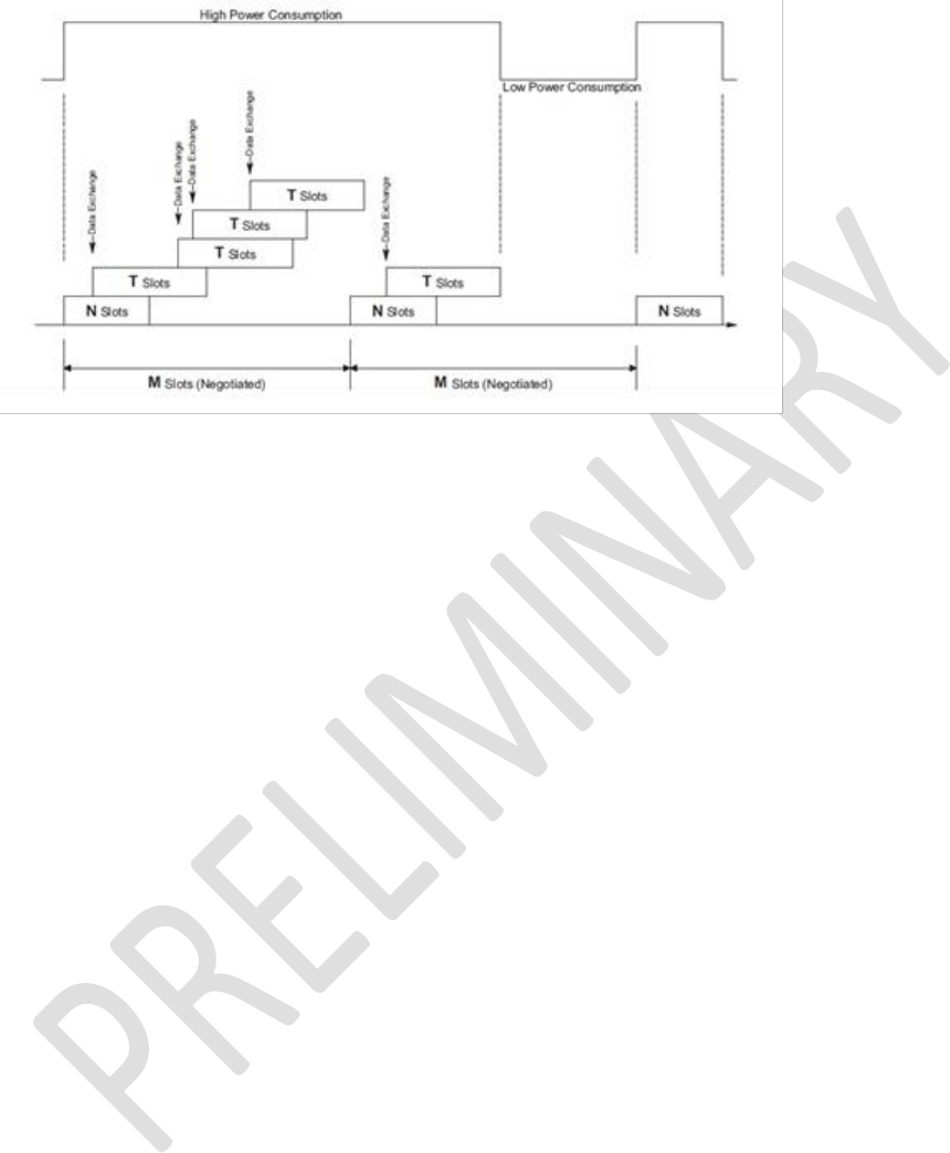
Enhanced Class 1 Bluetooth v2.1 Module
User’s Guide
Americas: +1-800-492-2320 Option 2
Europe: +44-1628-858-940
Hong Kong: +852-2923-0610
www.lairdtech.com/wireless
144
CONN-GUIDE-BT740_v0.2
Figure 13-1: Sniff Mode
13.8.2 UART Host Power Saving Facility
There are circumstances where a CPU driving the module consumes a lot of power and some means are
necessary to reduce that power consumption while the module is in a Bluetooth connection.
To facilitate that, the module has many GPIO pins, and using S Registers 50 to 65, one (and only one)
GPIO pin can configure with the value 13 so that it is an output configuration.
The state of the pin is 0 when the module’s UART transmit buffer is empty and 1 when there is at least
one byte waiting to be transmitted to the UART host.
Hence a workable power saving strategy by the CPU is illustrated in Figure 13-2.
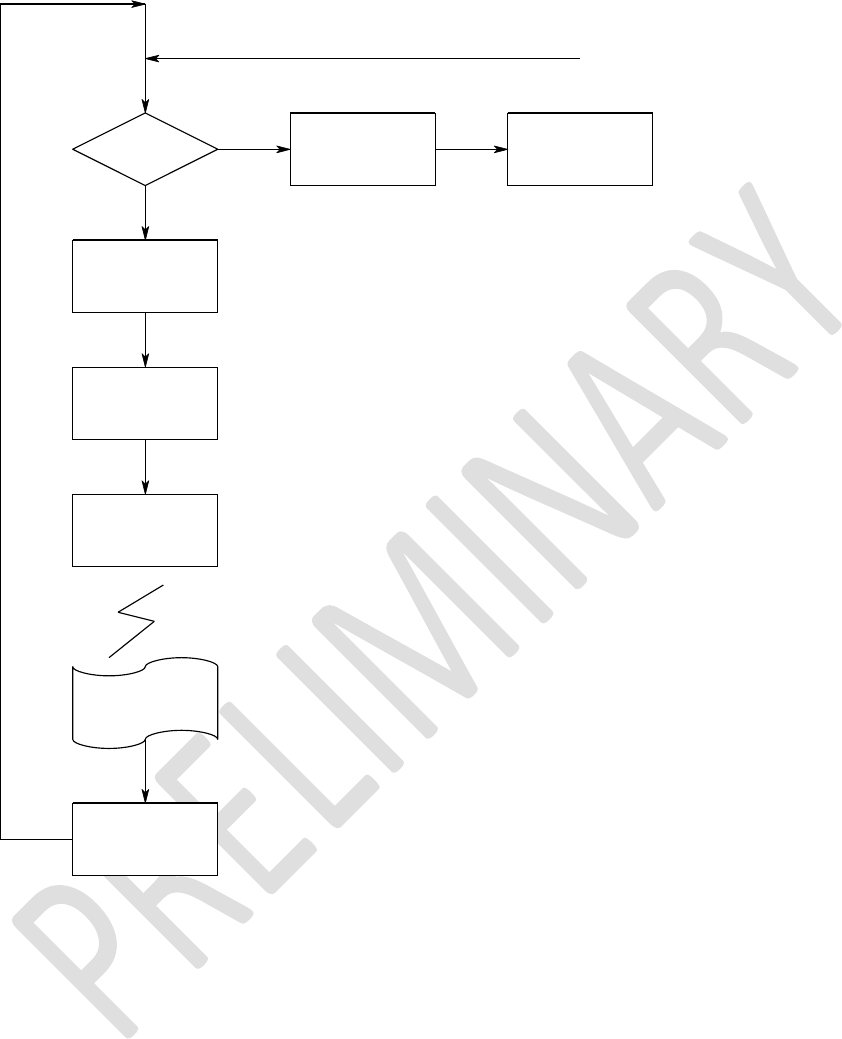
Enhanced Class 1 Bluetooth v2.1 Module
User’s Guide
Americas: +1-800-492-2320 Option 2
Europe: +44-1628-858-940
Hong Kong: +852-2923-0610
www.lairdtech.com/wireless
145
CONN-GUIDE-BT740_v0.2
Is PIN
High? Assert
RTS
Wait for data
to arrive from
Module
Deassert
RTS
Configure to wake
up when PIN
goes high
Go to Sleep
PIN goes high
Wake up
and
Assert RTS
Figure 13-2: CPU power saving strategy
13.8.3 Out of Band (OOB) Pairing
When two devices pair using the legacy procedure or the simple secure pairing method, the end result is
that they both end up with the same 16 byte random key. This key is subsequently used to authenticate
and encrypt subsequent connections. This means the list of pairing kept in each device as a minimum,
needs to store the peer Bluetooth address along with the 16 byte link key.
The Bluetooth specifications do not mandate that this link key shall only generate/exchange over the
Bluetooth radio, and in fact mention ‘Out-Of-Band’ (OOB) pairing as a valid means of expediting the
pairing of two devices.
The specification does not describe how the OOB pairing occurs.

Enhanced Class 1 Bluetooth v2.1 Module
User’s Guide
Americas: +1-800-492-2320 Option 2
Europe: +44-1628-858-940
Hong Kong: +852-2923-0610
www.lairdtech.com/wireless
146
CONN-GUIDE-BT740_v0.2
Whatever OOB means are chosen, it implies that some externally generated key has to be added to the
trusted device database in the device.
The module caters for this link key addition using the CMD_TRUSTED_DB_ADD command when in the
multipoint protocol mode and the AT+KY command when in the AT protocol mode.
13.8.4 Throughput Analysis
The following are factors that affect overall data throughput:
Baudrate – The baudrate at the UART determines the maximum throughput and has a theoretical
maximum of 80% of the baudrate if using ‘none’ parity and one stopbits. That theoretical maximum
reduces to around 67% if parity is enabled along with two stopbits.
Radio utilization – The radio utilization in the sense that at any time, up to three non-transient
operations could be active. The radio could be servicing on-going connections, it could be scanning
for inquiries, and it could be scanning for incoming connections. For the latter two, the scanning
operation has a duty cycle and the worst case of 100% has a major impact on the throughput as
the radio is time shared between the connections and the scanning operations.
RF connection quality –If the quality is bad and there are many retries of packets, then the
throughput can drop to close to zero before the connection automatically drops. For Basic Rate
connection packets, the best throughput limits to around 600 kbps in asymmetric data transfer
falling to around 400 kbps for symmetric transfers when using Base Rate RF packets. This can
triple when using EDR packets.
RFCOMM frame size – The size of the RFCOMM frame, which according to the BT spec can be a
value between 23 and 32767. The bigger the value the better, but the incremental gain around
1000 and above is negligible for embedded Bluetooth stack with limited RAM. This value sets via S
Register 11 in multipoint mode and 9011 in AT mode
MP packet payload size – In the multipoint protocol which is packet-based, the size of the MP
packet payload has an impact and in fact the packets should be as large as possible, and yet the
MP protocol limits the maximum payload to 253 bytes due to the length field of the packet being
only a single byte.
The charts that follow, where actual throughput is plotted against the RFCOMM frame size, show that in
multipoint mode the packet structure and scanning for inquiries and paging have a significant impact on
the throughput.
With regards to MP mode, the UART host should optimize performance by sending data to transmit in as
large packets as possible and completely disabling all scanning operations by setting S Registers 4 and 5
to zero.
It is entirely possible for the host to bombard the module with the worst case scenario of three byte
packets with just one data byte payload. In this case, if too many of these packets are sent and the
framesize is large (such as 64 and above), it is entirely possible for the module to lose the connection by
resetting. This happens because the module panics when it runs out of memory. On the rare
occasion that this happens, it is possible to mitigate this issue by increasing the value of S register 81. By
default this value is set to 30%.
Testing by Laird shows that with a framesize larger than 64 and sending a storm of three byte packets
(with one byte payload) and the default value of 30%, it is possible to panic the module into a reset.
Testing with a value of 50% in S Reg 81 solves the problem. But increasing the value of S Register 81
has an impact on how many simultaneous SPP connections can be sustained.

Enhanced Class 1 Bluetooth v2.1 Module
User’s Guide
Americas: +1-800-492-2320 Option 2
Europe: +44-1628-858-940
Hong Kong: +852-2923-0610
www.lairdtech.com/wireless
147
CONN-GUIDE-BT740_v0.2
Basically, users must fine tune S Registers 7,8,9,10,11,81 and MP packet sizes to ensure desired
throughput operation.
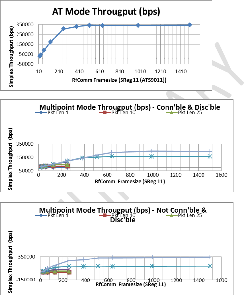
Enhanced Class 1 Bluetooth v2.1 Module
User’s Guide
Americas: +1-800-492-2320 Option 2
Europe: +44-1628-858-940
Hong Kong: +852-2923-0610
www.lairdtech.com/wireless
148
CONN-GUIDE-BT740_v0.2

Enhanced Class 1 Bluetooth v2.1 Module
User’s Guide
Americas: +1-800-492-2320 Option 2
Europe: +44-1628-858-940
Hong Kong: +852-2923-0610
www.lairdtech.com/wireless
149
CONN-GUIDE-BT740_v0.2
13.8.5 UART Protocol Selection & Indication Via GPIO
S register 255 selects either MP(1) or AT(2) protocol mode for communications over the UART.
If S Register 255 is set to zero, then it implies that a GPIO selects the protocol such that zero sets AT
mode and one for MP mode.
To configure a particular GPIO pin for this functionality, set the appropriate S Reg (in range 50 to 65) to a
value of 14. Only the first S Register in the range 50 to 65 is used, any further S Registers with the value
14 are ignored.
In addition, if at least one S register in the range 50 to 65 is set to a value of 15, then on power up that pin
configures as an output and sets to zero if AT protocol is active and one if MP is active.
If S Register 255 is zero and no GPIO is configured for this functionality, then the protocol defaults to MP.
13.8.6 Firmware Upgrade via UART
The module has the capability of upgrading the firmware via the UART port using a Windows PC based
utility supplied by Laird.
Firmware upgrades over the air are not planned as this is not inherently supported by the chipset vendor.
The upgrade process requires a direct connection to RX, TX, CTS, and RTS lines of the module via
appropriate RS232 level conversion, to a built-in serial port on the Windows PC.
The new firmware deploys in a .dfu file as and when new firmware is available.
If the user requires the ability to upgrade the firmware when their product is in the field, then provision
must be made so that the RX, TX, CTS, and RTS lines are exposed to the ‘outside’ world. This is
complicated if, as in most usage cases, a host microcontroller drives the BT module in the user’s end
product. In that case, the host microcontroller drive the module’s RX and CTS input lines and hence
cannot also be driven by a Windows PC unless those two lines are gated appropriately.
One solution is incorporating the hardware logic illustrated below and use a USB to Serial adapter as per
http://www.ftdichip.com/Products/Cables/USBTTLSerial.htm which does not require RS232 levels.
Note: This solution should work in theory and Laird does not warrant that it will work given it has not
been implemented and tested. The purpose of the suggestion is to make the user evaluate the
convenience arising from it and variations thereof.
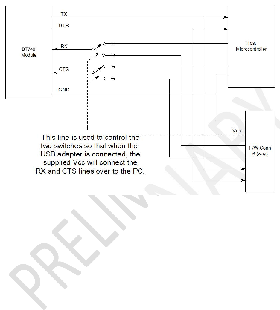
Enhanced Class 1 Bluetooth v2.1 Module
User’s Guide
Americas: +1-800-492-2320 Option 2
Europe: +44-1628-858-940
Hong Kong: +852-2923-0610
www.lairdtech.com/wireless
150
CONN-GUIDE-BT740_v0.2
13.8.7 The HCOMMAND & EVENT Values
The following is a listing of a snapshot of the file BMHOSTPROTOCOL.H at the time of this document’s
release. Laird does NOT guarantee that this listing is kept up to date.
For development purposes, please request the latest version of the appropriate ‘C’ header file.
//+++++++++++++++++++++++++++++++++++++++++++++++++++++++++++++++++++++++++++
//The following are COMMAND (octet 2) values in command/response packets
//+++++++++++++++++++++++++++++++++++++++++++++++++++++++++++++++++++++++++++
#define CMD_NO_OPERATION 0x01
#define CMD_READ_BDADDR 0x02
#define CMD_READ_SREG 0x03
#define CMD_WRITE_SREG 0x04
. . . .
. . . .

Enhanced Class 1 Bluetooth v2.1 Module
User’s Guide
Americas: +1-800-492-2320 Option 2
Europe: +44-1628-858-940
Hong Kong: +852-2923-0610
www.lairdtech.com/wireless
151
CONN-GUIDE-BT740_v0.2
. . . .
//+++++++++++++++++++++++++++++++++++++++++++++++++++++++++++++++++++++++++++
//The following are EVENT (octet 2) values in event packets
//+++++++++++++++++++++++++++++++++++++++++++++++++++++++++++++++++++++++++++
#define EVT_STATUS 0x81
#define EVT_INVALID_PKTSIZE 0x82
#define EVT_UNKNOWN_COMMAND 0x83
#define EVT_INQUIRY_RESULT 0x84
#define EVT_MODEM_STATUS 0x85
. . . .
. . . .
. . . .
13.8.1.1 STATUS Values
The following is a listing of a snapshot of the file MPSTATUS.H at the time of this document’s release.
Laird does NOT guarantee that this listing will be kept up to date.
For development purposes, please request the latest version of the appropriate ‘C’ header file.
#define MPSTATUS_OK 0x00
#define MPSTATUS_ILLEGAL_COMMAND 0x01
#define MPSTATUS_NO_CONNECTION 0x02
#define MPSTATUS_HARDWARE_FAIL 0x03
#define MPSTATUS_PAGE_TIMEOUT 0x04
. . . .
. . . .
. . . .

Enhanced Class 1 Bluetooth v2.1 Module
User’s Guide
Americas: +1-800-492-2320 Option 2
Europe: +44-1628-858-940
Hong Kong: +852-2923-0610
www.lairdtech.com/wireless
152
CONN-GUIDE-BT740_v0.2
14 AT APPLICATION EXAMPLES
14.1 Connection Management
Commands ATD, ATA, ATH, AT+BTP, and AT+BTG are all connection related and are discussed
generically in this section.
On connection, depending on the value of S Register 531, the module enters data pass through mode (S
Reg 531 = 0) or remains in command mode (S Reg 531 > 0).
In pass through mode, any data received from the host passes to the transmit buffer of the RF connection;
in the case of SPP (UUID=1101) and for all other profiles, it depends on whether a ‘canned’ mode is
provided. Data coming from the remote sends out to the host transparently – even in canned mode.
A ‘canned’ mode, which exists for HID profile, is where the incoming character from the host translates
into appropriate multi-byte packets expected by the peer. For example, with HID standard keyboard
profile where each key press results in an 8 byte HID INPUT report to the host, the ASCII character
appropriately expands into the relevant 8 bytes denoting that the key was pressed and then immediately
another 8 byte report denotes that the same key was unpressed.
If a canned mode is not available for a profile, then module is not allowed to get into pass-through mode.
In command and online mode, the command ATX”data” forces the module to send data and conversely
any incoming data presents to the host in an RX”data” asynchronous response.
14.1.1 Incoming Connections
The module can be configured using the AT+BTP or AT+BTG command so that it scans for incoming
connections from other Bluetooth devices. It can also be configured via S Register 512 to be in this mode
by default on power up.
When the lower layers detect an incoming call, a RING 123456789012 string sends to the host every
second. The command ATA accepts the connection and ATH rejects it.
On connection, if the S0 Register is >=0 and S504=0 then confirmation to the host is in the following form:
CONNECT <bd_addr>,<uuid>,<
Where ‘<uuid>’ is the UUID of the profile that accepted the connection.
14.1.2 Dropping Connections
In a conventional telephony modem, a call normally terminates by first sending a +++ escape sequence
enveloped by an escape sequence guard time (of the order of 100 to 1000 milliseconds) to enter local
command + connected mode, and then the ATH command to force a disconnection.
The Laird modules provide a couple of ways of dropping a connection. One method is similar to the
above, but instead uses a ^^^ character sequence. This eliminates ambiguity when a data call is in
progress via a mobile phone which established using the mobile phone’s Bluetooth AT modem. The
second method involves the host deasserting the DTR modem control line (DSR modem status line from
the module’s viewpoint) for longer than 500 milliseconds.
The escape sequence to force the module from pass-through mode and into command is as follows:

Enhanced Class 1 Bluetooth v2.1 Module
User’s Guide
Americas: +1-800-492-2320 Option 2
Europe: +44-1628-858-940
Hong Kong: +852-2923-0610
www.lairdtech.com/wireless
153
CONN-GUIDE-BT740_v0.2
<Guard time><Esc Chr><Guard time><Esc Chr><Guard time><Esc Chr><Guard time>
Where <Guard time> is 100 milliseconds.
The four guard time means that even when a file transfer is occurring and it happens to be full of <Esc
Chr> characters, it is not going to drop into command mode. This is because when transferring a file, it
happens as fast as possible and so the inter character gap will be significantly shorter than the <Guard
time>.
The <Esc Chr> character can be changed via the S2 register.
14.2 Profiles
This section describes all the profiles that the module is capable of making and accepting connection
when in AT mode.
14.3 Serial Port Profile (SPP)
UUID : 1101
You must set S Register 9003 bit 0 to make this profile active.
Outgoing connections are initiated using the command: “ATD<bd_addr>”
Incoming connections result in at least one “RING <bd_addr>” response to the host. If S Register 0 is a
non-zero value then after the appropriate number of RING responses the connection automatically
accepts and a “CONNECT <bd_addr>,1101,<” response sends to the host. If S Register 0 is 0, then the
incoming connection accepts by the host using the command ATA or rejected using ATH.
On connection, depending on the value of S Register 531, the module enters pass through mode (data
transparently exchanged between UART and air-side) or in command+online mode. In the latter, data
sends to the peer using the “ATX<string>” command and any data from the peer either dumps silently
(S531=1) or send to the host in an “RX<string>” asynchronous response (S531>1).
When in pass-through mode, the escape sequence ^^^ puts the module into command and online mode
so that a disconnection can initiate. A disconnection can also initiate by deasserting the DSR input line of
the module for more than 500 milliseconds.
On disconnection a “NO CARRIER” async response sends to the host.
14.4 HID Device Profile (HID)
UUID : 1124
S Register 9003 bit 1 must be set to make this profile active. In addition, S register 9039 must be set to 0
and above to enable a DEVICE HID profile and a negative value to enable a HOST HID profile.
Outgoing connections initiate using the command: “ATD<bd_addr>,1124”
Incoming connections are automatically accepted and a “CONNECT <bd_addr>,1124,<” sends to the
host.
With the HID profile, a built-in standard keyboard HID descriptor is supplied along with a canned mode of
operation. It enables a legacy device generating ASCII characters to present to a host as a compliant HID
keyboard.
In canned mode, each ASCII character (ASCII characters 128 and above are silently discarded) results in
two INPUT reports to the host. The first is a corresponding key press and the second is a corresponding
key unpress. When the host sends the 1 byte OUTPUT report sends to the host as-is.

Enhanced Class 1 Bluetooth v2.1 Module
User’s Guide
Americas: +1-800-492-2320 Option 2
Europe: +44-1628-858-940
Hong Kong: +852-2923-0610
www.lairdtech.com/wireless
154
CONN-GUIDE-BT740_v0.2
In non-canned mode (S Reg 531 > 0) the host has to send the raw 8 byte INPUT reports in the
ATX<String> command and conversely any OUTPUT reports from the host send to the host in
RX<string> asynchronous responses.
Disconnections from the module initiate via DSR deassertion. However, if the module is in non-canned
mode (S Register 531 > 0) then it is also possible to initiate a disconnection using the ATH command.
On disconnection a “NO CARRIER” async response sends to the host.
14.4.1 HID Descriptors
HIDs present their capabilities to a host in a HID descriptor which is essentially a block of octets that
describe the device’s capability and more importantly how events convey back and forth. This concept
was originally developed by the USB organisation and has been adopted by the Bluetooth SIG virtually
intact.
The HID descriptor contains information about INPUT and OUTPUT reports. They are both blocks of
octets described to contain various bit fields describing the event that needs conveyed to the peer.
Hence, at the end of the day, if a HID implementation was viewed as a communications black box
between a device and host, then it could be viewed as the device generating an INPUT report consisting
of X bytes which presents to the host and conversely an OUTPUT report consisting of Y bytes sends by
the host to the device.
In this module’s HID implementation, the module does not care about the content of those INPUT and
OUTPUT reports.
An INPUT report presents to the module by the UART host in a ATX<string> which then de-escapes and
sends as a single atomic packet to the remote host. Similarly, each OUTPUT package arrives atomically
in a single packet from the remote host which then sends to the UART host in a single RX<string>
message.
It was mentioned above that by default a standard keyboard HID descriptor is built into the firmware and
the default value of S Register 9039 makes the module connectable via a HID Device profile.
It is possible to download up to two custom HID device descriptors to store in the module’s non-volatile
memory. These custom HID device descriptors are then identified via a number in the range 0 to N. If S
Register 9039 changes to a value 1 to N+1, then on power up, if S Reg 9003 indicates that HID profile is
to be made available, it implements the appropriate custom HID descriptor in the service discovery
database.
When custom HID descriptors are downloaded and stored, there is no validation performed on the block
of data. This is because the module has no context to perform such validation.
In MP mode, to download a custom HID descriptor, you can use the utility MpBtHost.exe. Right click on
the window to invoke a pop-up menu and select “Upload HID Descriptor”. In the new dialog box, enter the
BLOB ID (recommend leave at 0) and HID ID to use. Then to use that descriptor update S Register 9039
with a value which is HidId+1.

Enhanced Class 1 Bluetooth v2.1 Module
User’s Guide
Americas: +1-800-492-2320 Option 2
Europe: +44-1628-858-940
Hong Kong: +852-2923-0610
www.lairdtech.com/wireless
155
CONN-GUIDE-BT740_v0.2
14.5 HDP Profile (Health Device Profile)
UUID : 1400,1401,1402
14.5.1 Background
Health Device Profile (HDP) is available on the module in both Agent and Manager roles as defined by
the Continua Alliance (see www.continua.org). There are two aspects to HDP: one is the transport layer,
for which only Bluetooth is catered for by this module (although the Continua Alliance has also ratified
others, for example USB), and the other aspect is IEEE data encapsulation.
The Laird module provides a tightly coupled integrated solution for a Weigh Scale Specialization Agent.
More specializations are provided in the future as and when there is demand via a firmware update.
It is assumed that the reader is familiar with all the HDP and IEEE documentation and relevant guidelines
published by the Continua Alliance. For HDP, it is assumed that the reader has access to the
specification from the Bluetooth SIG. For IEEE it is assumed that the reader has access to the
IEEE11073-20601 Optimised Exchange Protocol specification and the device specializations
specifications 11073-10401 through to 10499. For the Weigher Scale specialization embedded in the
module, the specification is 11073-10415. Obtain the IEEE standards from their website
standards.ieee.org, and Bluetooth HDP specifications at www.bluetooth.org.
The IEEE data specialization along with the Bluetooth physical transport defined in the appropriate
specifications is very dry and difficult to understand, and it is pointless to reproduce that information here
verbatim. However, an attempt is made to describe it from the module’s usage point of view where the
module and the functionality it provides is treated in a black box manner.
14.5.2 IEEE ‘Black Box’ Model
In a traditional health related environment, typical actors and props are the patient, instruments that
measure appropriate parameters, health professionals, and the (manual and/or automatic) archiving of
the records.
Over the years there have been many suppliers of the “instruments that measure appropriate parameters”
who have all provided proprietary methods for getting the data stored in records.
It has always been the role of the health professionals to ‘transcribe’ the data from the various
instruments into the archive records. The manual process presents risks associated with errors in the
transcribing process and so manufacturers provided even more proprietary solutions to automating that
task.
The Continua Alliance came about to address that confused picture with guidelines and a certification
process to ensure that a consistent inter-operable picture emerges with regards to the “instruments that
measure appropriate parameters” and the “method for getting the data stored in records”.
The last thing the Continua Alliance would want to do is dictate how any individual instrument (referred to
as an Agent) is physically designed, as that is best left to the engineers who know how best to design
them. Instead, they have specified abstract data models for the various types of instruments, which they
refer to as Data Specializations, and how they shall convey the data to an entity called a ‘Manager’ that
can be used to consistently store the data in an archive.
Examples of data specialization abstract models exist for weigh scales, thermometers, glucose meters,
blood pressure meters, ECGs, and many more will become available as they progress through various
stages in appropriate working groups. Any Continua Alliance member is free to recommend creation of

Enhanced Class 1 Bluetooth v2.1 Module
User’s Guide
Americas: +1-800-492-2320 Option 2
Europe: +44-1628-858-940
Hong Kong: +852-2923-0610
www.lairdtech.com/wireless
156
CONN-GUIDE-BT740_v0.2
data specializations as needed. Once ratified, the end result is always an abstract data model which
defines what data is pertinent for that instrument and how it shall be presented to the real world.

Enhanced Class 1 Bluetooth v2.1 Module
User’s Guide
Americas: +1-800-492-2320 Option 2
Europe: +44-1628-858-940
Hong Kong: +852-2923-0610
www.lairdtech.com/wireless
157
CONN-GUIDE-BT740_v0.2
14.5.3 Abstract Data Model
From a software engineer’s perspective, an abstract data model for an IEEE data specialization can best
be described as a collection of arrays of different types of data (which the specifications refer to as
attributes).
Each attribute is unambiguously defined to consist of a tag, a type, and the actual value. There is no
reliance on any programming language in the definition; it is purely a data model.
As a minimum there shall be one array of attributes called the ‘Medical Device System’, henceforth
referred to as an MDS which represents the properties and services of the device, independent of its
health data capabilities and its status. There shall also be one array of attributes called the Numeric,
henceforth referred to as NU which contains episodic measurements. There is also an RT-SA collection
which to represents continuous samples or waveforms.
Other collections exist and the reader is advised to refer to the IEEE11073-20601 standard for a definitive
list, described under the general heading of “Domain Information Model”.
At this point, imagine an HDP agent as just a collection of data records that can be read and written to
locally under program control and each data point is identified by its tag and publishes its data type. This
is analogous to a database table with 4 fields in each record. Three fields are called ‘Tag’, ‘Type’, ‘Value’,
and the fourth field is called ‘Collection Name’ such as MDS or NU or RT-SA.
You should further imagine this ‘database’ as accessible from a Manager over a physical transport media
such as Bluetooth or USB. The procedure a Manager uses to gain access to that database of attributes is
rigidly defined and standardised via a ‘Service Model’ using an association state machine defined in the
IEEE11073-20601 standard. This ‘Service Model’ is encapsulated in the Laird Module and the user is
encouraged to think of it in terms of a black box whose internal details are not relevant.
The picture that should emerge for the Laird module user who requires a data specialization is that of a
black box consisting of that conceptual database with a 4 field table and an ‘engine’ that implements the
association service model over Bluetooth so that it facilitates the mirroring of that said database at the
HDP manager end.
This picture then vastly simplifies the design and development of a health instrument that is required to be
Continua Alliance certified. The hope is that, the user is only required to have a general idea about the
content of the IEEE 11073-20601 and the data specialization IEEE11073-104xx standards.
The following subsections provide more details as to how you can control and manipulate the black box.
Please note that initially only a Weigh Scale data specialization as defined in 11073-10415 is available
embedded inside the black box. By ‘embedded’ it is implied that the MDS and NU collections are pre-
defined as per the standard and the attributes that may change values are exposed to the user for
manipulation.
In future it is hoped that a generic API will be exposed that allows any data specialization to be
downloaded and tested. If a user requires a specific data specialization then they are encouraged to
contact Laird with that request until that generic API is made available.
It is also pertinent to note here that once a user has a working instrument using this module, it is up to the
user to obtain Bluetooth Listing (quoting the QDID of the Laird module) prior to Continua Alliance testing
and certification.
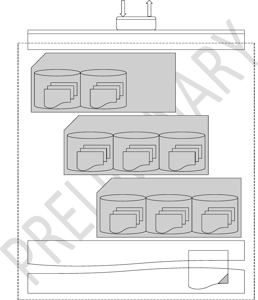
Enhanced Class 1 Bluetooth v2.1 Module
User’s Guide
Americas: +1-800-492-2320 Option 2
Europe: +44-1628-858-940
Hong Kong: +852-2923-0610
www.lairdtech.com/wireless
158
CONN-GUIDE-BT740_v0.2
14.5.4 HDP Agent Model
From a software perspective the HDP Agent implementation is as shown in the diagram below.
104xx Data Specialisation - B
104xx Data Specialisation - C
104xx Data Specialisation - Weigh Scale (4111)
Attributes
NU
Collection
Attributes
MDS
Collection
Attributes Attributes
NU
Collection Other
Collections
Attributes
MDS
Collection
Attributes Attributes
NU
Collection Other
Collections
Attributes
MDS
Collection
Bluetooth Stack
Uart
Responses/EventsCommands
IEEE/HDP 'Black Box' Agent Model
Bluetooth HDP Profile
Laird IEEE/HDP Services Encapsulation
4111,Scale
4104,Thermometer
xxx,something
SDP Record
Figure 14-1: HDP Agent implementation
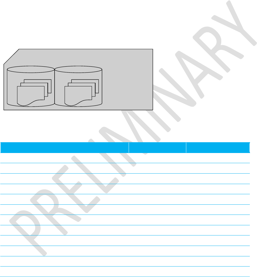
Enhanced Class 1 Bluetooth v2.1 Module
User’s Guide
Americas: +1-800-492-2320 Option 2
Europe: +44-1628-858-940
Hong Kong: +852-2923-0610
www.lairdtech.com/wireless
159
CONN-GUIDE-BT740_v0.2
The diagram shows that the agent model is the Bluetooth communications stack. The stack consists of an
SDP record that exposes to the outside world the data specializations it is capable of, a ‘Laird IEEE/HDP
Service Encapsulation’ layer which relays commands and responses to the host, and 0 or more instances
of Data Specializations. At the time of the first release of the firmware, only a Weigh Scale specialization
is offered.
All UART commands available to the host are provided so that the various entities in the black box can be
controlled or interrogated. Given there can be many agent specializations embedded in the firmware, they
are identified in various commands using a 16 bit handle.
14.5.5 Weigh Scale Data Specialization
The Weigh Scale Specialization (nominal code 4111) is embedded in the firmware is shown as below and
it contains a MDS and an NU object.
104xx Data Specialisation - Weigh Scale (4111)
Attributes
NU
Collection
Attributes
MDS
Collection
Figure 14-2: Embedded Weigh Scale Specialization
The MDS object is defined in the firmware with the following attributes:
Attribute Tag
Data Type
Comments
MDC_ATTR_ID_HANDLE
2337
HANDLE
Always: 0
MDC_ATTR_SYS_TYPE_SPEC_LIST
2650
TYPE_SPEC_LIST
Const
MDC_ATTR_ID_MODEL
2344
SYSTEM_MODEL
Var:SystemModel
MDC_ATTR_SYS_ID
2436
OCTET_STRING
Var:SystemId
MDC_ATTR_DEV_CONFIG_ID
2628
CONFIG_ID
1500 (0x05DC)
MDC_ATTR_ATTRIBUTE_VAL_MAP
2645
ATTR_VAL_MAP
Const
MDC_ATTR_ID_PROD_SPECN
2349
PROD_SPEC
Const
MDC_ATTR_TIME_ABS
2439
ABSOLUTE_TIME
Var:Time
MDC_ATTR_MDS_TIME_INFO
2629
MDS_TIME_INFO
Const
MDC_ATTR_POWER_STAT
2389
POWER_STATUS
Var:PowerStatus
MDC_ATTR_VAL_BATT_CHARGE
2460
INTU_16
Var: Batt, Chrg.
MDC_ATTR_TIME_BATT_REMAIN
2440
BatMeasure
Var:time_batt_remain

Enhanced Class 1 Bluetooth v2.1 Module
User’s Guide
Americas: +1-800-492-2320 Option 2
Europe: +44-1628-858-940
Hong Kong: +852-2923-0610
www.lairdtech.com/wireless
160
CONN-GUIDE-BT740_v0.2
The NU object is defined with the following attributes:
Attribute Tag
Data Type
Comments
MDC_ATTR_ID_HANDLE
2337
HANDLE
Always: 1
MDC_ATTR_ID_TYPE
2351
TYPE
Const
MDC_ATTR_METRIC_SPEC_SMAL
L
2630
METRIC_SPEC_SMALL
Const
MDC_ATTR_UNIT_CODE
2454
OID_TYPE
Var:Weight
Units
MDC_ATTR_ATTRIBUTE_VAL_MA
P
2645
ATTR_VAL_MAP
2646,2448
MDC_ATTR_TIME_STAMP_ABS
2448
ABSOLUTE_TIME
Var:Time
MDC_ATTR_NU_VAL_OBS_SIMP
2646
SIMPLE_NU_OBS_VAL
Var:Weight
MDC_ATTR_NU_ACCUR_MSMT
2378
FLOAT_TYPE
Always: 1
MDC_ATTR_MSMT_STAT
2375
MEASUREMENT_STATU
S
Var:Meas.
Stat.
The attributes commented as ‘variables’ expose to the host for reading and writing via the UART interface
using AT+HAG and AT+HAS commands respectively and are described in detail elsewhere in this
document.
The UART interface identifies the variable attributes mentioned above using an attribute ID and an
additional sub ID. The concept of ‘sub ID’ is a Laird artefact and is not part of any IEEE standard, but the
attribute ID is the same as those defined in the IEEE standard in most cases. The complete list for the
Weigh Scale specialization is as per the table below and should be used with the agent attribute
read/write commands AT+HAG and AT+HAS.
Note: The attribute values passed back and forth from the host are NOT validated in any way by the
firmware in the Laird module. It is up to the host to ensure that the correct data writes into an
attribute. Any illegal values are picked up at time of Continua Alliance certification testing which
prevents certification.
Table 14-1: Variable Attributes in Weigh Scale Specialization
Attribute Name (See IEEE spec for
format)
Attr ID
Sub ID
Size in bytes
Weight
2646
0
4
Weight Units
2454
0
2
Time
2448
0
8
Power Status
2389
0
2
Battery Charge
2460
0
2
Time Battery Remain – value
2440
0
4
Time Battery Remain – unit
2440
1
2
Measurement Status
2375
0
2
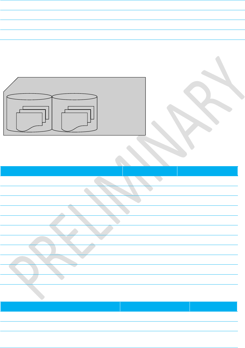
Enhanced Class 1 Bluetooth v2.1 Module
User’s Guide
Americas: +1-800-492-2320 Option 2
Europe: +44-1628-858-940
Hong Kong: +852-2923-0610
www.lairdtech.com/wireless
161
CONN-GUIDE-BT740_v0.2
System ID
2436
0
8
System Model – product name
2344
0
12
System Model – model name
2344
1
16
Serial Number
2349
0
8
14.5.6 Thermometer Data Specialization
The Thermometer Specialization (nominal code 4104) is embedded in the firmware is shown as below
and it contains a MDS and an NU object.
104xx Data Specialisation - Thermometer (4104)
Attributes
NU
Collection
Attributes
MDS
Collection
Figure 14-3: Embedded Thermometer Specialization
The MDS object is defined in the firmware with the following attributes:
Attribute Tag
Data Type
Comments
MDC_ATTR_ID_HANDLE
2337
HANDLE
Always: 0
MDC_ATTR_SYS_TYPE_SPEC_LIST
2650
TYPE_SPEC_LIST
Const
MDC_ATTR_ID_MODEL
2344
SYSTEM_MODEL
Var:SystemModel
MDC_ATTR_SYS_ID
2436
OCTET_STRING
Var:SystemId
MDC_ATTR_DEV_CONFIG_ID
2628
CONFIG_ID
800 (0x0320)
MDC_ATTR_ID_PROD_SPECN
2349
PROD_SPEC
Const
MDC_ATTR_TIME_ABS
2439
ABSOLUTE_TIME
Var:Time
MDC_ATTR_MDS_TIME_INFO
2629
MDS_TIME_INFO
Const
MDC_ATTR_POWER_STAT
2389
POWER_STATUS
Var:PowerStatus
MDC_ATTR_VAL_BATT_CHARGE
2460
INTU_16
Var: Batt, Chrg.
MDC_ATTR_TIME_BATT_REMAIN
2440
BAT_MEASURE
Var:time_batt_remain
The NU object is defined with the following attributes:
Attribute Tag
Data Type
Comments
MDC_ATTR_ID_HANDLE
2337
HANDLE
Always: 1
MDC_ATTR_ID_TYPE
2351
TYPE
Const
MDC_ATTR_METRIC_SPEC_SMAL
L
2630
METRIC_SPEC_SMALL
Const

Enhanced Class 1 Bluetooth v2.1 Module
User’s Guide
Americas: +1-800-492-2320 Option 2
Europe: +44-1628-858-940
Hong Kong: +852-2923-0610
www.lairdtech.com/wireless
162
CONN-GUIDE-BT740_v0.2
Attribute Tag
Data Type
Comments
MDC_ATTR_UNIT_CODE
2454
OID_TYPE
Var:Weight
Units
MDC_ATTR_TIME_PD_MSMT_ACT
IVE
2649
RELATIVE_TIME
Var:Time (int32)
MDC_ATTR_ATTRIBUTE_VAL_MA
P
2645
ATTR_VAL_MAP
2646,2448
MDC_ATTR_TIME_STAMP_ABS
2448
ABSOLUTE_TIME
Var:Time
MDC_ATTR_NU_VAL_OBS_BASIC
2636
BASIC_NU_OBS_VAL
Var:temperature
MDC_ATTR_NU_ACCUR_MSMT
2378
FLOAT_TYPE
Always: 1
MDC_ATTR_MSMT_STAT
2375
MEASUREMENT_STAT
US
Var:Meas. Stat.
The attributes commented as ‘variables’ expose to the host for reading and writing via the UART interface
using AT+HAG and AT+HAS commands respectively and are described in detail elsewhere in this
document.
The host identifies the variable attributes mentioned above on the UART interface using an attribute ID
and an additional sub ID. The concept of ‘sub ID’ is a Laird artefact and is not part of any IEEE standard,
but the attribute ID is the same as those defined in the IEEE standard in most cases. The complete list for
the Weigh Scale specialization is as per the table below and should be used with the agent attribute
read/write commands AT+HAG and AT+HAS.
Note: The attribute values passed back and forth from the host are NOT validated in any way by the
firmware in the Laird module. It is up to the host to ensure that the correct data writes into an
attribute. Any illegal values are picked up at time of Continua Alliance certification testing which
prevents certification.
Table 14-2: Variable Attributes in Thermometer Specialization
Attribute Name
(See IEEE spec for format)
Attr ID
Sub Id
Size in bytes
Temperature
2636
0
2
Temperature Units
2454
0
2
Absolute Time
2448
0
8
Power Status
2389
0
2
Battery Charge
2460
0
2
Time Battery Remain – value
2440
0
4
Time Battery Remain – unit
2440
1
2
Measurement Status
2375
0
2
System ID
2436
0
8
System Model – product name
2344
0
12
System Model – model name
2344
1
16

Enhanced Class 1 Bluetooth v2.1 Module
User’s Guide
Americas: +1-800-492-2320 Option 2
Europe: +44-1628-858-940
Hong Kong: +852-2923-0610
www.lairdtech.com/wireless
163
CONN-GUIDE-BT740_v0.2
Serial Number
2349
0
8
Measurement Active Period
2649
0
4

Enhanced Class 1 Bluetooth v2.1 Module
User’s Guide
Americas: +1-800-492-2320 Option 2
Europe: +44-1628-858-940
Hong Kong: +852-2923-0610
www.lairdtech.com/wireless
164
CONN-GUIDE-BT740_v0.2
14.5.7 Glucometer Data Specialization
The Glucometer Specialization (nominal code 4113) embedded in the firmware is shown as below and it
contains a MDS and an NU object.
104xx Data Specialisation - Glucometer (4113)
Attributes
NU
Collection
Attributes
MDS
Collection
Figure 14-4: Embedded Glucometer Specialization
The MDS object is defined in the firmware with the following attributes:
Attribute Tag
Data Type
Comments
MDC_ATTR_ID_HANDLE
2337
HANDLE
Always: 0
MDC_ATTR_SYS_TYPE_SPEC_LIST
2650
TYPE_SPEC_LIST
Const
MDC_ATTR_ID_MODEL
2344
SYSTEM_MODEL
Var:SystemModel
MDC_ATTR_SYS_ID
2436
OCTET_STRING
Var:SystemId
MDC_ATTR_DEV_CONFIG_ID
2628
CONFIG_ID
1700 (0x06A4)
MDC_ATTR_ID_PROD_SPECN
2349
PROD_SPEC
Const
MDC_ATTR_TIME_ABS
2439
ABSOLUTE_TIME
Var:Time
MDC_ATTR_MDS_TIME_INFO
2629
MDS_TIME_INFO
Const
MDC_ATTR_POWER_STAT
2389
POWER_STATUS
Var:PowerStatus
MDC_ATTR_VAL_BATT_CHARGE
2460
INTU_16
Var: Batt, Chrg.
MDC_ATTR_TIME_BATT_REMAIN
2440
BAT_MEASURE
Var:time_batt_remain
The NU object is defined with the following attributes:
Attribute Tag
Data Type
Comments
MDC_ATTR_ID_HANDLE
2337
HANDLE
Always: 1
MDC_ATTR_ID_TYPE
2351
TYPE
Const
MDC_ATTR_METRIC_SPEC_SMAL
L
2630
METRIC_SPEC_SMALL
Const
MDC_ATTR_UNIT_CODE
2454
OID_TYPE
Var:Weight Units
MDC_ATTR_ATTRIBUTE_VAL_MA
P
2645
ATTR_VAL_MAP
2646,2448

Enhanced Class 1 Bluetooth v2.1 Module
User’s Guide
Americas: +1-800-492-2320 Option 2
Europe: +44-1628-858-940
Hong Kong: +852-2923-0610
www.lairdtech.com/wireless
165
CONN-GUIDE-BT740_v0.2
Attribute Tag
Data Type
Comments
MDC_ATTR_TIME_STAMP_ABS
2448
ABSOLUTE_TIME
Var:Time
MDC_ATTR_NU_VAL_OBS_BASIC
2636
BASIC_NU_OBS_VAL
Var:temperature
MDC_ATTR_NU_ACCUR_MSMT
2378
FLOAT_TYPE
Always: 1
MDC_ATTR_MSMT_STAT
2375
MEASUREMENT_STAT
US
Var:Meas. Stat.
The attributes commented as ‘variables’ expose to the host for reading and writing via the UART interface
using AT+HAG and AT+HAS commands respectively and are described in detail elsewhere in this
document.
The host identifies the variable attributes mentioned above on the UART interface using an attribute ID
and an additional sub ID. The concept of ‘sub ID’ is a Laird artefact and is not part of any IEEE standard,
but the attribute ID is the same as those defined in the IEEE standard in most cases. The complete list for
the Weigh Scale specialization is as per the table below and should be used with the agent attribute
read/write commands AT+HAG and AT+HAS.
Note: The attribute values passed back and forth from the host are NOT validated in any way by the
firmware in the Laird module. It is up to the host to ensure that the correct data is written into an
attribute. Any illegal values are picked up at time of Continua Alliance certification testing which
prevents certification.
Table 14-3: Variable Attributes in Thermometer Specialization
Attribute Name
(See IEEE spec for format)
Attr ID
Sub ID
Size in bytes
Blood Glucose
2636
0
2
Blood Glucose Units
2454
0
2
Absolute Time
2448
0
8
Power Status
2389
0
2
Battery Charge
2460
0
2
Time Battery Remain – value
2440
0
4
Time Battery Remain – unit
2440
1
2
Measurement Status
2375
0
2
System ID
2436
0
8
System Model – product name
2344
0
12
System Model – model name
2344
1
16
Serial Number
2349
0
8

Enhanced Class 1 Bluetooth v2.1 Module
User’s Guide
Americas: +1-800-492-2320 Option 2
Europe: +44-1628-858-940
Hong Kong: +852-2923-0610
www.lairdtech.com/wireless
166
CONN-GUIDE-BT740_v0.2
14.6 Agent Related AT Commands
This section describes all the commands used to manage the Agent role for HDP.
14.6.1 Connection to an HDP Manager
Command:
AT+HAAhhhh
Response:
<cr,lf> OK<cr,lf>
Or
<cr,lf>ERROR nn<cr,lf>
Or
<cr,lf>HAD:ASSOCIATE xxxx<cr,lf>OK<cr,lf>
Or
<cr,lf> HAD:DISASSOCIATE xxxx<cr,lf>ERROR nn<cr,lf>
Description:
This command establishes a connection to an HDP manager and
associates the agent with it so that attribute data can be exchanged. The
Bluetooth address of the HDP manager and the agent specialization that
needs to associate is defined by the handle ‘hhhh’, which is pre-obtained
using command AT+HAB.
This command waits for the procedure to complete successfully or
otherwise before responding with OK or ERROR. If the agent is already
associated then an immediate OK is the response.
If the agent is not already associated then a Bluetooth connection
initiates and as soon as a connection establishes, the association state
machine progresses through to negotiating a configuration and then
ultimately confirms the association. If association is successful, then a
“HDA:ASSOCIATE …..” asynchronous response sends to the host. If
association fails (because BT connection failed or configuration could not
be negotiated) then the async response “HDA:DISASOCIATE …” sends
to the host. An OK or ERROR response terminates the procedure.
Note: If S Reg 9071 is non-zero, then there is an automatic
disassociation after a time specified by that register. The timer
restarts every time a scan report sends to the manager.
SReg Required Settings: Bit 2 set in S9003 and S9070=0

Enhanced Class 1 Bluetooth v2.1 Module
User’s Guide
Americas: +1-800-492-2320 Option 2
Europe: +44-1628-858-940
Hong Kong: +852-2923-0610
www.lairdtech.com/wireless
167
CONN-GUIDE-BT740_v0.2
14.6.2 Bind a Data Specialization
Command:
AT+HAB<bd_addr>,iiii
Response:
<cr,lf>hhhh<cr,lf>OK<cr,lf>
Or
<cr,lf>ERROR nn<cr,lf>
Description:
This command binds a data specialization identified by the nominal code
‘iiii’ (for example 4111 = Weigh Scale) with an HDP manager identified by
the Bluetooth address ‘<bd_addr>’. For this command to be successful,
the data specialization identified by ‘iiii’ has to be pre-embedded in the
firmware. Although the firmware allows multiple bindings to the same
specialization, please be aware that it is the same object and each
instance does not have a unique set of attributes.
If the binding is successful, then a 16 bit handle ‘hhhh’ (a decimal
number) returns, which is then used as a parameter in many subsequent
commands.
SReg Required Settings: Bit 2 set in S9003 and S9070=0
14.6.3 Disassociate an Agent
Command:
AT+HADhhhh
Response:
<cr,lf>OK<cr,lf>
Or
<cr,lf>> HAD:DISASSOCIATE xxxx<cr,lf>OK<cr,lf>
Or
<cr,lf>ERROR nn<cr,lf>
Description:
This command disassociates an agent identified by the handle hhhh from
a manager.
This command waits for the procedure to complete successfully or
otherwise before responding with OK or ERROR. If the agent is already
disassociated then an immediate OK is the response.
SReg Required Settings: Bit 2 set in S9003 and S9070=0
Command:
AT+HAEiiii,”name”
Response:
<cr,lf>OK<cr,lf>
Or
<cr,lf>ERROR nn<cr,lf>
Description:
This command must be issued prior to sending the AT+HAL commands
and includes the data specialization endpoint ‘iiii’ with the string “name”
as an HDP source (agent) in the SDP record that is exposed to potential
peers. This tells potential peers that the device offers a ‘iiii’ data
specialization source.
Without this entry in the SDP record, a manager is not able to make a
connection to the HDP agent, although it is rare for a manager to initiate
connections in typical usage scenarios.
SReg Required Settings: Bit 2 set in S9003 and S9070=0
Command:
AT+HAGhhhh,aaaa,ssss
Response:
<cr,lf>hhhhhhhhhhhhhh<cr,lf>OK<cr,lf>

Enhanced Class 1 Bluetooth v2.1 Module
User’s Guide
Americas: +1-800-492-2320 Option 2
Europe: +44-1628-858-940
Hong Kong: +852-2923-0610
www.lairdtech.com/wireless
168
CONN-GUIDE-BT740_v0.2
Or
<cr,lf>ERROR nn<cr,lf>
Description:
This command reads (gets) the value of one of the variable attributes
identified by ‘aaaa’ and sub ID ‘ssss’ in the attribute collections for that
agent identified by the handle ‘hhhh’. For the embedded weigh scale data
specialization this command reads the value of an attribute listed in Table
14-1.
The value always returns as a string of hexadecimal digits representing
the binary value, and the size of that string is even. Different attributes
have different sizes.
SReg Required Settings: Bit 2 set in S9003 and S9070=0
Command:
AT+HAL
Response:
<cr,lf>OK<cr,lf>
Or
<cr,lf>ERROR nn<cr,lf>
Description:
This command must issue after sending at least one AT+HAE command,
and registers and activates the SDP record with information supplied in
the AT+HAE commands.
Without the SDP record, a manager is not able to make a connection to
the HDP agent, although it is rare for a manager to initiate connections in
typical usage scenarios.
SReg Required Settings: Bit 2 set in S9003 and S9070=0
Command:
AT+HARhhhh,pppp[,aaaa[,aaaa[…]]]
Response:
<cr,lf> OK<cr,lf>
Or
<cr,lf>ERROR nn<cr,lf>
Description:
This command triggers a scan report for person ID ‘pppp’ (16 bit decimal
number) from the agent identified by handle ‘hhhh’.
If the agent is not associated with the bound manager (see AT+HAB)
then it first triggers the start of an association.
Once association exists, a scan report sends.
If [,aaaa[,aaaa[…]]] is absent from the command, then the standard scan
report as identified by the attribute MDC_ATTR_ATTRIBUTE_VAL_MAP
in the NU collection sends to the manager. Otherwise, the
[,aaaa[,aaaa[…]]] can be a list of any attribute mentioned in the NU
collection. For example, to send a scan report with just the measurement
status, just specify the single value 2375.
Please note that only attributes mentioned in the NU collection are
allowed. Any ‘aaaa’ value not found in the NU collection is silently
ignored.
SReg Required Settings: Bit 2 set in S9003 and S9070=0
Command:
AT+HAShhhh,aaaa,ssss,hhhhhhhhhhhh
Response:
<cr,lf> OK<cr,lf>
Or
<cr,lf>ERROR nn<cr,lf>
Description:
This command writes (sets)a new value ‘hhhhhhhhhhhh’ to one of the
variable attributes (identified by ‘aaaa’ and sub ID ‘ssss’) in the attribute

Enhanced Class 1 Bluetooth v2.1 Module
User’s Guide
Americas: +1-800-492-2320 Option 2
Europe: +44-1628-858-940
Hong Kong: +852-2923-0610
www.lairdtech.com/wireless
169
CONN-GUIDE-BT740_v0.2
collections for the agent identified by the handle ‘hhhh’. For the
embedded weigh scale data specialization, this command writes to an
attribute listed in Table 14-1.
The value ‘hhhhhhhhh’ is in hexadecimal and is NOT validated in any
way apart from the requirement that it shall be twice the size in bytes as
specified for that attribute.
SReg Required Settings: Bit 2 set in S9003 and S9070=0
14.6.4 Agent Related AT Asynchronous Responses
This section describes all the asynchronous responses sent to the host by the HDP Agent. Each
response is framed by a <cr,lf> at the start and end.
Command:
No Command. This is a status message.
Response:
HDA:DISASSOCIATED hhhh
Description:
This response sends the host when an association attempt fails (as a result of
AT+HAA or AT+HAR commands) or when an association terminates by either
AT+HAD or due to loss of Bluetooth connectivity. The parameter ‘hhhh’ which
is a 16 bit decimal number identifies the agent.
Command:
No Command. This is a status message.
Response:
HDA:ASSOCIATED hhhh,iiii,cccc,sssssssssssss
Description:
This response sends to the host when a successful association happens for
the agent identified by ‘hhhh’ (16 bit decimal number). For completeness, the
data specialization nominal code ‘iiii’ (16 bit decimal) and the device
configuration ID ‘cccc’ (16 bit decimal), that got negotiated with the manager,
is also provided. The 16 character parameter ‘ssssssss’ specifies the system
ID of the manager.
Note: An agent data specialization can be basic as specified in the
relevant spec, or one of the more enhanced ones which have more
capabilities. For example, with the weigh scale, Laird provides for
the basic MDS collection, but it is possible to specify multiple MDS
collections which expose more functionality (e.g. body mass index
attributes). These extended collections are identified by
configuration IDs and are offered to a manager during the
association phase in descending order of complexity until the
manager accepts one that it can work with.
Command:
No Command. This is a status message.
Response:
HDA:TIME hhhh,ccyymmddhhmmssaa
Description:
This response sends to the host when a manager sends new time information
by writing to the MDC_ATTR_TIME_ABS attribute in the MDS collection of
the agent identified by ‘hhhh’. The time ccyymmddhhmmssaa is a 16
character hexadecimal value which is encoded as follows:
CC Century (e.g. 14==20)
YY Year (e.g. 0B==11)
MM Month (e.g. 0C==12)
DD Day (e.g 1F==31)
HH Hour (e.g. 17==23)
MM Minutes (e.g 32==50)

Enhanced Class 1 Bluetooth v2.1 Module
User’s Guide
Americas: +1-800-492-2320 Option 2
Europe: +44-1628-858-940
Hong Kong: +852-2923-0610
www.lairdtech.com/wireless
170
CONN-GUIDE-BT740_v0.2
SS Seconds (e.g. 2F==47)
AA Hundreths of seconds (e.g 63==99)
For example, the data and time 12 Feb 2011, 16:45:33.78 sends as
140B020C102D214E
14.6.5 HDP Manager Model
From a software perspective the HDP Manager implementation is as shown in the diagram below and the
functionality is provided mainly to enable prototyping and regression testing of agent specializations.
There are many far more capable HDP Managers available which are hosted on a PC. For example, the
latest Toshiba Bluetooth Stack is HDP capable and there are imminent BlueZ releases for Linux PCs.
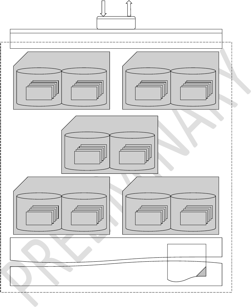
Enhanced Class 1 Bluetooth v2.1 Module
User’s Guide
Americas: +1-800-492-2320 Option 2
Europe: +44-1628-858-940
Hong Kong: +852-2923-0610
www.lairdtech.com/wireless
171
CONN-GUIDE-BT740_v0.2
Associated Agent Object Associated Agent Object
Associated Agent Object
Associated Agent Object Associated Agent Object
Bluetooth Stack
Uart
Responses/EventsCommands
Laird IEEE/HDP Services Encapsulation
4111,Scale
4104,Thermometer
xxx,something
SDP Record
IEEE/HDP 'Black Box' Manager Model
Partial List
of MDS Attrs Partial List of
NU Attributes
Attributes Attributes
Partial List
of MDS Attrs Partial List of
NU Attributes
Attributes Attributes
Partial List
of MDS Attrs Partial List of
NU Attributes
Attributes Attributes
Partial List
of MDS Attrs Partial List of
NU Attributes
Attributes Attributes
Partial List
of MDS Attrs Partial List of
NU Attributes
Attributes Attributes
Bluetooth HDP Profile
Figure 14-5: Manager model with Bluetooth communications stack
Figure 14-5 shows that the Manager model consists of the Bluetooth communications stack. The stack
consists of:
an SDP record that exposes to the outside world the data specializations it is capable of accepting
as sinks
a ‘Laird IEEE/HDP Service Encapsulation’ layer which relays commands and responses to the host

Enhanced Class 1 Bluetooth v2.1 Module
User’s Guide
Americas: +1-800-492-2320 Option 2
Europe: +44-1628-858-940
Hong Kong: +852-2923-0610
www.lairdtech.com/wireless
172
CONN-GUIDE-BT740_v0.2
0 or more instances of Specialization Associations.
These ‘Associated Agent Objects’ are transient and come into existence only when an agent successfully
associates. The associated process results in the top few attributes in the MDS and NU collections
caching in the Manager which the host reads using the AT+HMG command after an association.
Just like the Agent end, the Manager indicates via its SDP record which Data Specializations it is capable
of sinking, and commands analogous to the ones provided for the Agent model have been provided to
manipulate that SDP record content.
14.7 Manager Related AT Commands
This section describes all the commands used to manage the agent role for HDP.
Command:
AT+HMEiiii,”name”
Response:
<cr,lf>OK<cr,lf>
Or
<cr,lf>ERROR nn<cr,lf>
Description:
This command must issue prior to sending the AT+HML commands and
includes the data specialization endpoint ‘iiii’ with the string “name” as a HDP
sink in the SDP record that is exposed to potential agents. This tells potential
peers that the device offers a ‘iiii’ data specialization sink.
Without this entry in the SDP record, an appropriate agent is not able to
make a connection to the HDP Manager.
SReg Required Settings: Bit 2 set in S9003 and S9070=1
Command:
AT+HMGhhhh,oooo,aaaa
Response:
<cr,lf>hhhhhhhhhhhhhh<cr,lf>OK<cr,lf>
Or
<cr,lf>ERROR nn<cr,lf>
Description:
This command reads the value of one of the cached attributes for an agent
identified by ‘hhhh’. The parameter ‘oooo’ is for 0 for attributes in the MDS
collection cache and ‘1’ for the NU collection cache and ‘aaaa’ is the ID of
the attribute to read.
The value always returns as a string of hexadecimal digits representing the
binary value, and the size of that string is even. Different attributes have
different sizes.
SReg Required Settings: Bit 2 set in S9003 and S9070=1
Command:
AT+HML
Response:
<cr,lf>OK<cr,lf>
Or
<cr,lf>ERROR nn<cr,lf>
Description:
This command must issue after sending at least one AT+HME command and
registers and activate the SDP record with information supplied in the
AT+HME commands.
Without the SDP record, an agent is not able to make a connection to the
HDP manager.

Enhanced Class 1 Bluetooth v2.1 Module
User’s Guide
Americas: +1-800-492-2320 Option 2
Europe: +44-1628-858-940
Hong Kong: +852-2923-0610
www.lairdtech.com/wireless
173
CONN-GUIDE-BT740_v0.2
SReg Required Settings: Bit 2 set in S9003 and S9070=1
Command:
AT+HMThhhh, ccyymmddhhmmssaa
Response:
<cr,lf> OK<cr,lf>
Or
<cr,lf>ERROR nn<cr,lf>
Description:
This command sends the current data and time to the associated agent
identified by handle ‘hhhh’.
The time ccyymmddhhmmssaa is a 16 character hexadecimal value which is
encoded as follows:
CC Century (e.g. 14==20)
YY Year (e.g. 0B==11)
MM Month (e.g. 0C==12)
DD Day (e.g 1F==31)
HH Hour (e.g. 17==23)
MM Minutes (e.g 32==50)
SS Seconds (e.g. 2F==47)
AA Hundreths of seconds (e.g 63==99)
For example, the data and time 12 Feb 2011, 16:45:33.78 sends as
140B020C102D214E
SReg Required Settings: Bit 2 set in S9003 and S9070=1
14.7.1 Manager Related AT Asynchronous Responses
This section describes all the asynchronous responses sent to the host by the HDP Manager. Each
response is framed by a <cr,lf> at the start and end.
Command:
No Command. This is a status message.
Response:
HDM:DISASSOCIATED hhhh
Description:
This response sends to the host when an association terminates by an
agent or due to loss of Bluetooth connectivity. The parameter ‘hhhh’ which
is a 16 bit decimal number identifies the agent.
Command:
No Command. This is a status message.
Response:
HDM:ASSOCIATED hhhh,iiii,cccc,sssssssssssss

Enhanced Class 1 Bluetooth v2.1 Module
User’s Guide
Americas: +1-800-492-2320 Option 2
Europe: +44-1628-858-940
Hong Kong: +852-2923-0610
www.lairdtech.com/wireless
174
CONN-GUIDE-BT740_v0.2
Description:
This response sends to the host when a successful association happens for
the agent identified by ‘hhhh’ (16 bit decimal number). For completeness,
the data specialization nominal code ‘iiii’ (16 bit decimal) and the device
configuration ID ‘cccc’ (16 bit decimal) that got negotiated with the
manager, is also provided. The 16 character parameter ‘ssssssss’ specifies
the system ID of the agent.
Note: An agent data specialization can be basic as specified in the
relevant spec, or more enhanced with more capabilities. For
example, with the weigh scale Laird provides for the basic MDS
collection, it is possible to specify multiple MDS collection which
expose more functionality (such as body mass index attributes).
These extended collections are identified by configuration IDs and
are offered to a manager during the association phase in
descending order of complexity until the manager accepts one that it
can work with.
Command:
No Command. This is a status message.
Response:
HDM:SCANPERIOD hhhh<more>
Description:
This response sends to the host when a scan report receives from agent
identified by handle ‘hhhh’. Since a scan report can consist of data values for
many attributes, this report is formatted with embedded <lf> characters as
follows:
<cr><lf>HDM:SCANREPORT hhhh:pppp
<lf>O:oooo
<lf>A:aaaa,ddd..ddd
<lf>A:aaaa,ddd..ddd
…
<lf>O:oooo
<lf>A:aaaa,ddd..ddd
<lf>A:aaaa,ddd..ddd
…
…
<cr><lf>
Where <lf>O: identifies the collection object (oooo == 1 for NU etc) and then
subsequence <lf>A: lines consist of value pairs aaaa,ddd.ddd where ‘aaaa’ is
the attribute nominal code and ddd...ddd is its value in hexadecimal. The size
of the value for each attribute is specified in the IEEE standards.

Enhanced Class 1 Bluetooth v2.1 Module
User’s Guide
Americas: +1-800-492-2320 Option 2
Europe: +44-1628-858-940
Hong Kong: +852-2923-0610
www.lairdtech.com/wireless
175
CONN-GUIDE-BT740_v0.2
14.7.1.1 Sample Host/Module Message Sequence
In a typical weigh scale usage, the sequence of commands (red) and responses (blue) from the module is
as follows, where it assumed that the both ends start of from factory default state:
===================================== ========================================
AGENT MANAGER
===================================== ========================================
ats9003=5
OK
ats9070=1
OK
at&w
OK
ats9003=5
OK
ats9070=0
OK
at&w
OK
============================
PAIRING
============================
AT+BTW0016a4fef005
OK
PAIR 0 0016A4FEF005 PAIR 0 0016A4FEF004
============================
REGISTER SDP RECORDS
============================
AT+HME4111,"scale"
OK
AT+HML
OK
AT+HAE4111,"scale"
OK
AT+HAB0016a4fef005,4111
46392
OK
AT+HAL
OK
============================
ASSOCIATE
============================
AT+HAA46392
HDA:ASSOCIATED 46392,4111,1500,4C414952444D4752
HDM:ASSOCIATED 29364,4111,1500,0016A4FEF004B538
OK
============================
READ ATTIBUTES @ MANAGER
============================
AT+HMG29364,0,2628
05DC
OK

Enhanced Class 1 Bluetooth v2.1 Module
User’s Guide
Americas: +1-800-492-2320 Option 2
Europe: +44-1628-858-940
Hong Kong: +852-2923-0610
www.lairdtech.com/wireless
176
CONN-GUIDE-BT740_v0.2
============================
READ ATTIBUTES @ AGENT
============================
AT+HAG46392,2646,0
0000004B
OK
============================
WRITE ATTIBUTES @ AGENT
============================
AT+HAS46392,2646,0,00000123
OK
AT+HAG46392,2646,0
00000123
OK
============================
SEND TIME
============================
AT+HMT29364,140B020C102D214E
OK
HDA:TIME 46392,140B020C102D214E
============================
SEND FIXED SCAN REPORT
============================
AT+HAR46392,1234
HDM:SCANREPORT 29364:1234
O:1
A:2646,00000123
A:2448,2011021216453378
OK
============================
SEND VARIABLE SCAN REPORT
============================
AT+HAR46392,1234,2454,2448,2646,2375
HDM:SCANREPORT 29364:1234
O:1
A:2454,06C3
A:2448,2011021216453378
A:2646,0000004B
A:2375,8000
OK
============================
DISASSOCIATE
============================
AT+HAD46392
OK
HDA:DISASSOCIATED 46392 HDM:DISASSOCIATED 29364

Enhanced Class 1 Bluetooth v2.1 Module
User’s Guide
Americas: +1-800-492-2320 Option 2
Europe: +44-1628-858-940
Hong Kong: +852-2923-0610
www.lairdtech.com/wireless
177
CONN-GUIDE-BT740_v0.2
14.7.2 Authentication and Encryption
The module and firmware is BT v2.1 compliant so it uses Simple Secure Pairing (SSP) to authenticate
devices to trust, and only invokes a legacy pairing procedure when a peer device is v2.0 or older.
It is not possible to configure the unit to be only capable of legacy pairing and still have v2.1 approvals.
The purpose of pairing, whether legacy or SSP, is to generate the same random 16 byte key at both ends.
The key is then used in subsequent connections for authentication and encryption.
14.7.3 Legacy Pairing
A legacy pairing procedure is automatically used when pairing is initiated (by either end) and the peer is
approved to v2.0 and below.
14.7.3.1 Outgoing
To initiate a pairing, the host shall submit the command “AT+BTW<bd_addr>” to which it gets an
immediate OK or ERROR response. The host then waits for a “PIN ? <bd_addr>” response to which it
responds with the command AT+BTK=”pincode”.
When the pairing procedure completes, the module sends to the host the following asynchronous
response: “PAIR N <bd_addr>”. N is 0 when the pairing is successful, 1 for a timeout, and 2 for a generic
failure (for example, mismatching pincode).
14.7.3.2 Incoming
The module has to be in at least connectable mode for it to participate in a pairing initiated from a legacy
peer. The first indication the host gets that an incoming legacy pairing has initiated is when it receives the
asynchronous response “PIN ? <bd_addr>”. To this, the host responds with a shared pincode conveyed
in the command AT+BTK=”pincode”.
When the pairing procedure completes, the module sends to the host the following asynchronous
response: “PAIR N <bd_addr>”. N is 0 when the pairing is successful, 1 for a timeout, and 2 for a generic
failure (for example, mismatching pincode).
14.7.4 Simple Secure Pairing
Simple secure pairing was introduced in v2.1 of the Bluetooth specification to simplify the pairing
procedure so it did not rely on a pre-shared pincode and so that all connections are forced to be
encrypted. Unlike pre v2.1 devices, it is not possible to create connections without encryption.
Simple secure pairing uses the Diffie-Hellman public/private encryption methodology to expedite a
common 128 bit key at both ends. This eliminates the need for pre-shared pincodes but introduces the
‘man in the middle’ (MITM) attack vulnerability.
To address the MITM vulnerability the concept of verification via a 6 digit passcode was also added. A 6
digit passcode was selected, as that reduces the probability of a random MITM attack succeeding to one
in a million.
The 6 digit passcode is NOT a pre shared code, but is a random 6 digit artefact derived from the Diffie-
Hellman calculations such that knowledge of that 6 digit number by an attacker cannot result in back-
calculation of the 128 bit key that generated.
For a user to interact and process the 6 digit passcode the SSP procedure requires that each Bluetooth
device have an I/O capability which is one of the following:

Enhanced Class 1 Bluetooth v2.1 Module
User’s Guide
Americas: +1-800-492-2320 Option 2
Europe: +44-1628-858-940
Hong Kong: +852-2923-0610
www.lairdtech.com/wireless
178
CONN-GUIDE-BT740_v0.2
None
Display Only
Display with a Yes/No button
Keyboard only
This I/O capability exchanges by the two peers going through a pairing procedure so that the optimal user
interaction selects at both ends. For example, if one end admits to keyboard only and the other to Display
only, then the two negotiate that the display end shows the passcode with an appropriate prompt to get
the user at the other end to type in the passcode.
When either has ‘none’ capability, then pairing procedure completes without any MITM protection by both
ends automatically accepting the passcode generated by the pairing algorithm.
14.7.4.1 I/O Capability
The I/O capability of the module is set via S Register 6 (9006 in AT mode) where the value to set is as
follows:
12 = No I/O capability
13 = Display with Yes/No
14 = Keyboard only
15 = Display Only
When both ends are keyboard only, you can enter a pre-shared 6 digit number.
When both ends are Display Only it is unlikely the two devices have services that are of use to either and
so it could be contrived combination.
14.7.4.2 Outgoing
To initiate a pairing, the host shall submit the command “AT+BTW<bd_addr>” to which it gets an
immediate OK or ERROR response. The host then shall wait for a “PASSKEY? N <bd_addr>” response
to which it shall respond with the command AT+BTK=”passcode” or “AT+BTKY” or “AT+BTKN”
depending on the value of N in the “PASSKEY?” message.
When the pairing procedure completes, the module sends to the host the following asynchronous
response: “PAIR N <bd_addr>”. N is 0 for a successful pairing, 1 for a timeout, and 2 for a generic failure
(for example, mismatching pincode).
As you can see, the host is able to determine if SSP or legacy pairing is in progress because in the
former the challenge message is “PASSKEY?” whereas in the latter it is “PIN ?”
14.7.4.3 Incoming
The module has to be in at least connectable mode for it to participate in a pairing initiated from a SSP
capable peer. The first indication the host may get is that an incoming pairing has initiated is when it
receives the asynchronous response “PASSKEY? N <bd_addr>”. To this, the host responds with the
command AT+BTK=”passcode” or “AT+BTKY” or “AT+BTKN” depending on the value of N in the
“PASSKEY?” message.
When the pairing procedure completes, and for ‘just works’, the module sends to the host the following
asynchronous response: “PAIR N <bd_addr>”. N is 0 for a successful pairing, 1 for a timeout, and 2 for a
generic failure (for example, mismatching pincode).

Enhanced Class 1 Bluetooth v2.1 Module
User’s Guide
Americas: +1-800-492-2320 Option 2
Europe: +44-1628-858-940
Hong Kong: +852-2923-0610
www.lairdtech.com/wireless
179
CONN-GUIDE-BT740_v0.2
As you can see, the host is able to determine if SSP or legacy pairing is in progress because in the
former the challenge message is “PASSKEY?” whereas in the latter it is “PIN ?”. In the ‘just works’
scenario the PAIR 0 message informs the host that a pairing is complete.
14.7.4.4 Host processing of the “PASSKEY? N” response
The full format of the PASSKEY? message to the host is:
PASSKEY? N <bd_addr>[,passcode]
N is 1, 2, or 3 and “,passcode” is not present when N=3.
When N=1, this message requires the host to just display the passcode. The module does not expect any
confirmation from the host.
When N=2, this message requires the host to display the passcode so that the user can accept or reject
the pairing. The host sends the AT+BTKY command to accept the pairing, and to reject it sends
AT+BTKN.
When N=3, the passcode is not provided and the host submits the AT+BTK=”passcode” command. To
reject, it can send any value not matching the passcode displayed at the remote end OR send
AT+BTK=””.
In the case of pairing where the I/O capability is none, the pairing occurs with ‘just works’ procedure
where both ends automatically accept the pairing. In this case the module becomes aware that the pairing
happened when it receives the “PAIR N <bd_addr>” response.
14.7.4.5 GPIO Access via SReg 619 and 620
The GPIO can be read and written to in AT mode via S registers 619 and 620.
SReg 620 reads the current states of all GPIO pins and displays as hex value with a ‘&’ prefix.
To write to output pins, a nonzero mask MUST first write to S register 619.
Subsequently, any value written to S Reg 620 only affects GPIO pins which have a corresponding bit in S
Reg 619 set to 1.
14.7.5 GPIO Exchange via RFCOMM Modem Signalling
There is a modem signalling message in an SPP connection that exchanges between peers. It conveys
the status of 4 bits called RTR, RTC, DV, and IC, which normally map to DTR/DSR, RTS/CTS, DCD and
RI respectively. This on-air message is transparent and happens in the ‘background’ as and when
required.
The firmware in the module allows GPIO to map to those 4 bits. In total 8 GPIO pins can be mapped: 4
for inputs mapped to the bits that are sent to the peer, and 4 for outputs updated when a modem
signalling message arrives from the peer.
It is not necessary to map all 8 bits and it is perfectly acceptable to have no pins mapped (which is the
default).
S Registers 651 to 654 inclusive specify OUTPUT pins which update when a modem signal message
arrives from a peer.
S Registers 661 to 664 inclusive specify INPUT pins which are monitored for changes of state, and when
detected result in a modem signal to be sent to the peer.

Enhanced Class 1 Bluetooth v2.1 Module
User’s Guide
Americas: +1-800-492-2320 Option 2
Europe: +44-1628-858-940
Hong Kong: +852-2923-0610
www.lairdtech.com/wireless
180
CONN-GUIDE-BT740_v0.2
As a result, it is possible to convey the state of a digital pin to the peer with some inherent latency. The
latency depends on the quality of the RF connection, and even with the best of connection the user must
test actual timings to check that the latency is acceptable for the use case.

Enhanced Class 1 Bluetooth v2.1 Module
User’s Guide
Americas: +1-800-492-2320 Option 2
Europe: +44-1628-858-940
Hong Kong: +852-2923-0610
www.lairdtech.com/wireless
181
CONN-GUIDE-BT740_v0.2
14.7.6 Enhanced Inquiry Responses
Bluetooth 2.1 specification allows up to 240 bytes of extended inquiry data. On BT740-Sx modules, this
data is limited to a maximum length based on firmware builds due to internal memory restrictions.
Extended inquiry data transmits e.g. the friendly name, UUIDs of supported profiles, or user defined data
within the inquiry process and without a Bluetooth connection.
The architecture for managing EIR data is composed of a BLOB buffer, a set of AT commands around
them, and:
Baseband (EIR data visible to inquiring devices)
RAM buffer (allows accumulation of data)
EIR persistent store (non-volatile buffer, copied to baseband at boot time)
As the input buffer length for one AT command is limited, there is a RAM buffer to accumulate several
short data packets. The accumulated data of the RAM buffer can be copied to the baseband where it
becomes visible to other inquiring devices immediately.
The content of the RAM buffer can copy to the EIR persistent store. If the EIR persistent store contains
data, it copies to the baseband automatically at boot time. This allows a flexible usage of extended inquiry
data. For example, data with a low data rate (e.g. temperature) can transmit without creating a connection
between Bluetooth devices, however without the benefits of encryption and authentication.
The command AT+BTB is provided to manage EIR data in AT mode.
14.7.6.1 EIR Data Format
When passing EIR data (“<data>”) to AT commands (AT+BTB=”<data>” / AT+BTB+”<data>”), each byte
should be presented by its ASCII representation whenever it is a printable character.
Each non-printable ASCII character must be presented as 2 hex digits with a preceding ‘\’. For example, a
byte of decimal value 5 is presented as “\05” because the ASCII character of 05d is not printable.
A decimal value of 43 should be presented as ‘+’ because ‘+’ is the ASCII character representing 43d.
The module also accepts “\2B” (the hexadecimal presentation of 43d) but at the price of two redundant
characters.
Exceptions:
‘“’ (quotation mark) must be presented as \22
‘\’ (backslash) must be presented as \5C
When querying the content of the BLOB, non-printable ASCII characters are presented by 2 hex digits
with preceding ‘\’.
Exceptions:
‘“’ (quotation mark) is presented as \22
‘\’ (backslash) is presented as \5C
‘,’ (comma) is presented as \2C
Any data passed to the baseband must match the format defined in the Bluetooth Specification Version
2.1 + EDR [1], vol3, Part C – Generic Access Profile, 8 Extended Inquiry Response Data Format (page
1305 in the *.pdf file).
The AT command interpreter does not perform any checks on the baseband data format.
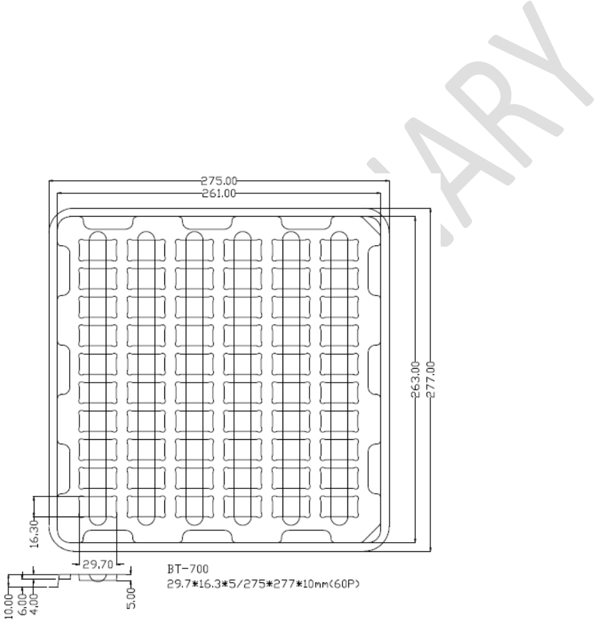
Enhanced Class 1 Bluetooth v2.1 Module
User’s Guide
Americas: +1-800-492-2320 Option 2
Europe: +44-1628-858-940
Hong Kong: +852-2923-0610
www.lairdtech.com/wireless
182
CONN-GUIDE-BT740_v0.2
15 SURFACE MOUNT MODULES
15.1 Introduction
Laird surface mount modules are designed to conform to all major manufacturing guidelines. This section
provides additional guidance for mounting the module. This section is considered a living document and
is updated as new information is presented.
The modules are designed to meet the needs of a number of commercial and industrial applications. The
modules are designed to be easily manufactured and conform to current automated manufacturing
processes.
15.2 Shipping
Modules ship in Electrostatic Discharge (ESD)-safe trays that can load into most manufacturers pick and
place machines. Layouts of the trays are provided in Figure 15-1.
Figure 15-1: BT740 Shipping Tray Details
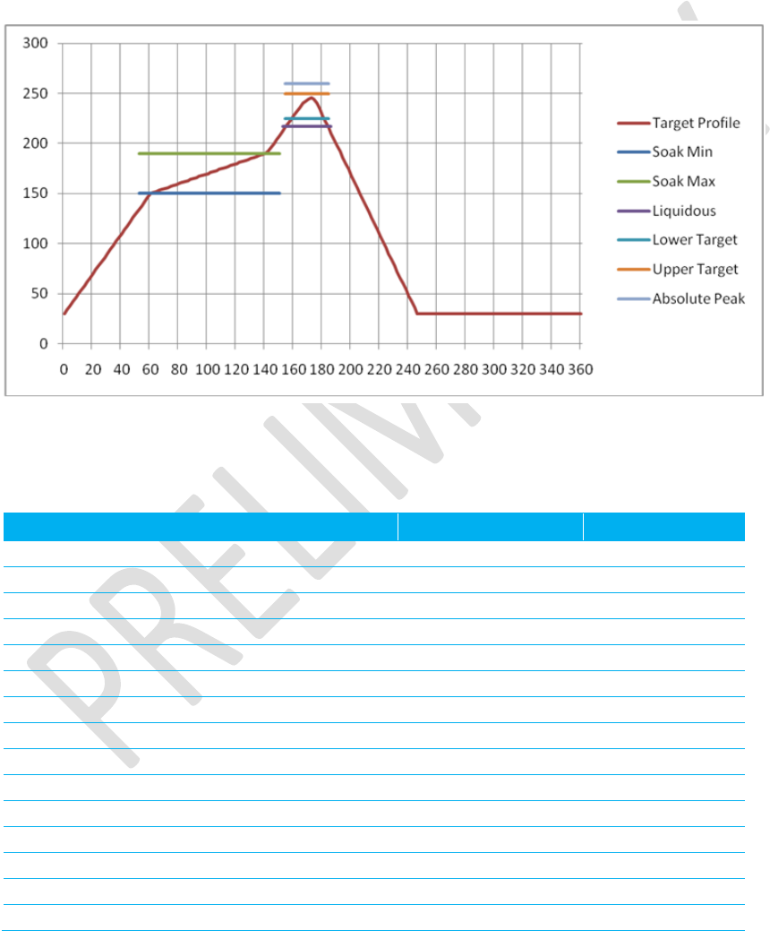
Enhanced Class 1 Bluetooth v2.1 Module
User’s Guide
Americas: +1-800-492-2320 Option 2
Europe: +44-1628-858-940
Hong Kong: +852-2923-0610
www.lairdtech.com/wireless
183
CONN-GUIDE-BT740_v0.2
15.3 Reflow Parameters
Laird surface mount modules are designed to be easily manufactured, including reflow soldering to a PCB.
Ultimately it is the responsibility of the customer to choose the appropriate solder paste and to ensure
oven temperatures during reflow meet the requirements of the solder paste. Laird’s surface mount
modules conform to J-STD-020D1 standards for reflow temperatures.
WARNING: During reflow, modules should not be above 260° for more than 30 seconds.
Figure 15-2: Recommended Reflow Temperature
Temperatures should not exceed the minimums or maximums presented in Table 15-1.
Table 15-1: Recommended maximum and minimum temperatures
Specification
Value
Unit
Temperature Inc./Dec. Rate (max)
1~3
°C / Sec
Temperature Decrease rate (goal)
2-4
°C / Sec
Soak Temp Increase rate (goal)
.5 - 1
°C / Sec
Flux Soak Period (Min)
70
Sec
Flux Soak Period (Max)
120
Sec
Flux Soak Temp (Min)
150
°C
Flux Soak Temp (max)
190
°C
Time Above Liquidous (max)
70
Sec
Time Above Liquidous (min)
50
Sec
Time In Target Reflow Range (goal)
30
Sec
Time At Absolute Peak (max)
5
Sec
Liquidous Temperature (SAC305)
218
°C
Lower Target Reflow Temperature
240
°C
Upper Target Reflow Temperature
250
°C
Absolute Peak Temperature
260
°C

Enhanced Class 1 Bluetooth v2.1 Module
User’s Guide
Americas: +1-800-492-2320 Option 2
Europe: +44-1628-858-940
Hong Kong: +852-2923-0610
www.lairdtech.com/wireless
184
CONN-GUIDE-BT740_v0.2
16 FCC REGULATORY STATEMENTS
Family
US/FCC
CANADA/IC
BT7x0
SQGBT700
3147A-BT700
Part #
Form Factor
Tx Output
Antenna
BT740-SA-XX
Surface Mount
18dBm
Chip
BT740-SC-XX
Surface Mount
18dBm
U.FL
*Last two slots "XX" in Part # are for production firmware release changes. Can be values 01-99, aa-zz
The BT740 family is designed to operate with the antennas listed below, with a maximum gain of 2dBi.
The required antenna impedance is 50 ohms.
Table 16-1: Qualified antennas
Item
Part Number
Mfg.
Type
Gain (dBi)
1
AT3216-B2R7HAAT
ACX
Chip
0.5
2
MAF94045
Laird
PCB
2
3
ACC-008
EZURIO
Ceramic Patch
2
4
WRR2400- IP04-
B(MAF94019)
Laird
Dipole
1.5
5
WTC2450-IP04-
K(MAF94006)
Laird
Dipole
2
6
S181FL-L-RMM-
2450S
Nearson
(Laird)
Dipole
2
Note: The OEM is free to choose another vendor’s antenna of like type and equal or lesser gain as an
antenna appearing in the table and still maintain compliance. Reference FCC Part 15.204(c)(4)
for further information on this topic. To reduce potential radio interference to other users, the
antenna type and gain should be chosen so that the equivalent isotropic radiated power (EIRP)
is not more than that permitted for successful communication.
16.1 Power Exposure Information
In general, there are two agency classifications for RF radiation exposure in wireless applications: mobile
and portable.
Mobile – A mobile device is a transmitting device designed in such a way that a separation distance of at
least 20 cm is normally maintained between the transmitter's radiating structures and the body of the user
or nearby persons. The BT740 is fully modular approved for mobile and fixed applications (reference FCC
Part 2.1091 for further details on mobile devices).
This transmitter must not be co-located or operating in conjunction with any other antenna or transmitter.
Portable – Portable is a classification of equipment where the user, in general, is within 20 cm of the
transmitting antenna. Portable equipment is further broken down into two classes: within 2.5 cm of human
contact and beyond 2.5 cm. The BT740 does not hold a portable approval classification due to its peak
output power and modular approval restrictions. Customers who want to use the BT730 in portable

Enhanced Class 1 Bluetooth v2.1 Module
User’s Guide
Americas: +1-800-492-2320 Option 2
Europe: +44-1628-858-940
Hong Kong: +852-2923-0610
www.lairdtech.com/wireless
185
CONN-GUIDE-BT740_v0.2
applications require further RF evaluation. Contact a qualified test house or a Laird representative for
further information on this topic (reference FCC Part 2.1093 for further details on portable devices).
Maximum Permissible Exposure report was created and shows the minimum distances for Public and
Occupational use of the BT740.
Note: Occupational Limit Minimum Distance = 1.5 cm. Public Limit Minimum Distance = 3 cm.
Note: This equipment was tested and found to comply with the limits for a Class B digital device,
pursuant to Part 15 of the FCC Rules. These limits are designed to provide reasonable
protection against harmful interference in a residential installation. This equipment generates,
uses, and can radiate radio frequency energy and, if not installed and used in accordance with
the instructions, may cause harmful interference to radio communications. However, there is no
guarantee that interference does not occur in a particular installation. If this equipment does
cause harmful interference to radio or television reception, which can be determined by turning
the equipment off and on, the user is encouraged to correct the interference by one or more of
the following measures:
Reorient or relocate the receiving antenna
Increase the separation between the equipment and the receiver
Connect the equipment to an outlet on a circuit that is different from that to which the
receiver
is connected.
Consult the dealer or an experienced radio/TV technician for help
CAUTION: THIS DEVICE COMPLIES WITH PART 15 OF THE FCC RULES AND INDUSTRY CANADA
LICENSE-EXEMPT RSS STANDARD(S). OPERATION IS SUBJECT TO THE FOLLOWING TWO
CONDITIONS: (1) THIS DEVICE MAY NOT CAUSE HARMFUL INTERFERENCE, AND (2) THIS
DEVICE MUST ACCEPT ANY INTERFERENCE RECEIVED, INCLUDING INTERFERENCE THAT MAY
CAUSE UNDESIRED OPERATION.
CAUTION: The OEM should have the device incorporating with the BT740 tested by a qualified test
house to verify compliance with FCC Part 15 Subpart B limits for unintentional radiators.
CAUTION: Any changes or modifications not expressly approved by Laird could void the user’s authority
to operate the equipment.

Enhanced Class 1 Bluetooth v2.1 Module
User’s Guide
Americas: +1-800-492-2320 Option 2
Europe: +44-1628-858-940
Hong Kong: +852-2923-0610
www.lairdtech.com/wireless
186
CONN-GUIDE-BT740_v0.2
16.2 OEM Responsibilities
This device is intended only for OEM integrators under the following conditions:
1) The antenna must be installed such that 20 cm is maintained between the antenna and users, and
2) The transmitter module may not be co-located with any other transmitter or antenna.
As long as 2 conditions above are met, further transmitter test will not be required. However, the OEM
integrator is still responsible for testing their end-product for any additional compliance requirements
required with this module installed
IMPORTANT NOTE:
In the event that these conditions can not be met (for example certain laptop configurations or co-location
with another transmitter), then the FCC authorization is no longer considered valid and the FCC ID can
not be used on the final product. In these circumstances, the OEM integrator will be responsible for re-
evaluating the end product (including the transmitter) and obtaining a separate FCC authorization.
End Product Labeling
This transmitter module is authorized only for use in device where the antenna may be installed such that
20 cm may be maintained between the antenna and users. The final end product must be labeled in a
visible area with the following: “Contains FCC ID: SQGBT700”.
Manual Information To the End User
The OEM integrator has to be aware not to provide information to the end user regarding how to install or
remove this RF module in the user’s manual of the end product which integrates this module.
The end user manual shall include all required regulatory information/warning as show in this manual.

Enhanced Class 1 Bluetooth v2.1 Module
User’s Guide
Americas: +1-800-492-2320 Option 2
Europe: +44-1628-858-940
Hong Kong: +852-2923-0610
www.lairdtech.com/wireless
187
CONN-GUIDE-BT740_v0.2
Industry Canada (IC) Warning:
This device complies with RSS-210 of the Industry Canada Rules. Operation is subject to the following
two conditions: (1) This device may not cause harmful interference, and (2) this device must accept any
interference received, including interference that may cause undesired operation.
Ce dispositif est conforme à la norme CNR-210 d'Industrie Canada applicable aux appareils radio
exempts de licence. Son fonctionnement est sujet aux deux conditions suivantes: (1) le dispositif ne doit
pas produire de brouillage préjudiciable, et (2) ce dispositif doit accepter tout brouillage reçu, y compris
un brouillage susceptible de provoquer un fonctionnement indésirable.
Radiation Exposure Statement:
This equipment complies with IC radiation exposure limits set forth for an uncontrolled environment. This
equipment should be installed and operated with minimum distance 20cm between the radiator & your
body.
Déclaration d'exposition aux radiations:
Cet équipement est conforme aux limites d'exposition aux rayonnements IC établies pour un
environnement non contrôlé. Cet équipement doit être installé et utilisé avec un minimum de 20 cm de
distance entre la source de rayonnement et votre corps.
This device is intended only for OEM integrators under the following conditions: (For module
device use)
1) The antenna must be installed such that 20 cm is maintained between the antenna and users.
2) The transmitter module may not be co-located with any other transmitter or antenna.
As long as 2 conditions above are met, further transmitter test will not be required. However, the OEM
integrator is still responsible for testing their end-product for any additional compliance requirements
required with this module installed.
Cet appareil est conçu uniquement pour les intégrateurs OEM dans les conditions suivantes:
(Pour utilisation de dispositif module)
1) L'antenne doit être installée de telle sorte qu'une distance de 20 cm est respectée entre l'antenne et
les utilisateurs.
2) Le module émetteur peut ne pas être coïmplanté avec un autre émetteur ou antenne.
Tant que les 2 conditions ci-dessus sont remplies, des essais supplémentaires sur l'émetteur ne seront
pas nécessaires. Toutefois, l'intégrateur OEM est toujours responsable des essais sur son produit final
pour toutes exigences de conformité supplémentaires requis pour ce module installé.
IMPORTANT NOTE:
In the event that these conditions can not be met (for example certain laptop configurations or co-location
with another transmitter), then the Canada authorization is no longer considered valid and the IC ID can
not be used on the final product. In these circumstances, the OEM integrator will be responsible for re-
evaluating the end product (including the transmitter) and obtaining a separate Canada authorization.

Enhanced Class 1 Bluetooth v2.1 Module
User’s Guide
Americas: +1-800-492-2320 Option 2
Europe: +44-1628-858-940
Hong Kong: +852-2923-0610
www.lairdtech.com/wireless
188
CONN-GUIDE-BT740_v0.2
NOTE IMPORTANTE:
Dans le cas où ces conditions ne peuvent être satisfaites (par exemple pour certaines configurations
d'ordinateur portable ou de certaines co-localisation avec un autre émetteur), l'autorisation du Canada
n'est plus considéré comme valide et l'ID IC ne peut pas être utilisé sur le produit final. Dans ces
circonstances, l'intégrateur OEM sera chargé de réévaluer le produit final (y compris l'émetteur) et
l'obtention d'une autorisation distincte au Canada.
End Product Labeling
This transmitter module is authorized only for use in device where the antenna may be installed such that
20 cm may be maintained between the antenna and users. The final end product must be labeled in a
visible area with the following: “Contains IC: ”.
Plaque signalétique du produit final
Ce module émetteur est autorisé uniquement pour une utilisation dans un dispositif où l'antenne peut être
installée de telle sorte qu'une distance de 20cm peut être maintenue entre l'antenne et les utilisateurs. Le
produit final doit être étiqueté dans un endroit visible avec l'inscription suivante: "Contient des IC: ".
Manual Information To the End User
The OEM integrator has to be aware not to provide information to the end user regarding how to install or
remove this RF module in the user’s manual of the end product which integrates this module.
The end user manual shall include all required regulatory information/warning as show in this manual.
Manuel d'information à l'utilisateur final
L'intégrateur OEM doit être conscient de ne pas fournir des informations à l'utilisateur final quant à la façon
d'installer ou de supprimer ce module RF dans le manuel de l'utilisateur du produit final qui intègre ce
module.
Le manuel de l'utilisateur final doit inclure toutes les informations réglementaires requises et
avertissements comme indiqué dans ce manuel.

Enhanced Class 1 Bluetooth v2.1 Module
User’s Guide
Americas: +1-800-492-2320 Option 2
Europe: +44-1628-858-940
Hong Kong: +852-2923-0610
www.lairdtech.com/wireless
189
CONN-GUIDE-BT740_v0.2
1. CE Regulatory
The BT740 has been tested for compliance with relevant standards for the EU market. The OEM should
consult with a qualified test house before entering their device into an EU member country to make sure
all regulatory requirements have been met for their complete device.
The BT740 was tested with a 2dBi dipole antenna. The OEM is free to use any manufacturer’s antenna
and type of antenna but it must be <2dBi to remain in compliance with the Laird reports.
Reference the Declaration of Conformities listed below for a full list of the standards that the modules
were tested to. Test reports are available upon request.

Enhanced Class 1 Bluetooth v2.1 Module
User’s Guide
Americas: +1-800-492-2320 Option 2
Europe: +44-1628-858-940
Hong Kong: +852-2923-0610
www.lairdtech.com/wireless
190
CONN-GUIDE-BT740_v0.2
17 EU DECLARATIONS OF CONFORMITY
17.1 BT740-SA
Manufacturer:
Laird
Product:
BT740-SA
EU Directive:
RTTE 1995/5/EC
Conformity Assessment:
Annex IV
Reference standards used for presumption of conformity:
Article Number
Requirement
Reference standard(s)
3.1a
Health and Safety
EN 60950-1:2006
3.1b
Protection requirements with
respect to electromagnetic
compatibility
EN 301 489-1 V1.8.1
EN 301 489-17 V2.1.1
Emissions:
EN55022:2006/A1:2000/A2:2006(Cla
ssB)
Immunity:
EN61000-4-2:1995/A1:1998/A2:2001
EN61000-4-3:2002/A1:2002
3.2
Means of the efficient use of
the radio frequency spectrum
EN 300 328 V1.7.1 (2006-10)
Declaration:
We, Laird Inc., declare under our sole responsibility that the essential radio test suites have been carried
out and that the above product to which this declaration relates is in conformity with all the applicable
essential requirements of Article 3 of the EU Directive 1995/5/EC, when used for its intended purpose.
Place of Issue:
Laird Technologies
Saturn House, Mercury Park
Wooburn Green
HP100HH,
United Kingdom
tel:+44 (0)1628 858 940
fax: +44 (0)1628 528 382
Date of Issue:
June 2013
Name of Authorized Person:
Andrew Dobbing, Engineering Manager
Signature:

Enhanced Class 1 Bluetooth v2.1 Module
User’s Guide
Americas: +1-800-492-2320 Option 2
Europe: +44-1628-858-940
Hong Kong: +852-2923-0610
www.lairdtech.com/wireless
191
CONN-GUIDE-BT740_v0.2
17.2 BT740-SC
Manufacturer:
Laird
Product:
BT740-SC
EU Directive:
RTTE 1995/5/EC
Conformity Assessment:
Annex IV
Reference standards used for presumption of conformity:
Article Number
Requirement
Reference standard(s)
3.1a
Health and Safety
EN 60950-1:2006
3.1b
Protection requirements with respect to
electromagnetic compatibility
EN 301 489-1 V1.8.1
EN 301 489-17 V2.1.1
Emissions:
EN55022:2006/A1:2000/A2:2006(ClassB)
Immunity:
EN61000-4-2:1995/A1:1998/A2:2001
EN61000-4-3:2002/A1:2002
3.2
Means of the efficient use of the radio
frequency spectrum
EN 300 328 V1.7.1 (2006-10)
Declaration:
We, Laird Inc., declare under our sole responsibility that the essential radio test suites have been carried
out and that the above product to which this declaration relates is in conformity with all the applicable
essential requirements of Article 3 of the EU Directive 1995/5/EC, when used for its intended purpose.
Place of Issue:
Laird Technologies
Saturn House, Mercury Park
Wooburn Green
HP100HH,
United Kingdom
tel:+44 (0)1628 858 940
fax: +44 (0)1628 528 382
Date of Issue:
June 2013
Name of Authorized Person:
Andrew Dobbing, Engineering Manager
Signature:
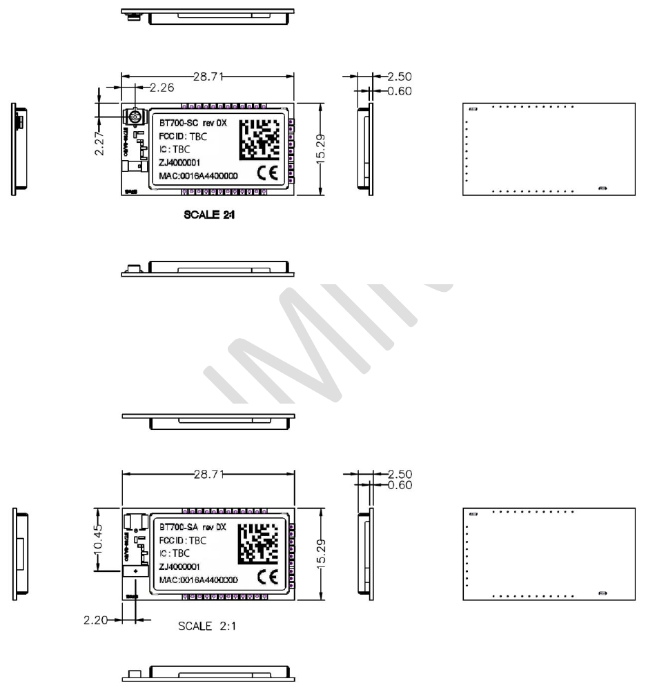
Enhanced Class 1 Bluetooth v2.1 Module
User’s Guide
Americas: +1-800-492-2320 Option 2
Europe: +44-1628-858-940
Hong Kong: +852-2923-0610
www.lairdtech.com/wireless
192
CONN-GUIDE-BT740_v0.2
18 MECHANICAL DETAILS
18.1 BT740-SC Mechanical Details
Figure 18-1: BT740-SC mechanical details
Module Keep-Out Area: An area of 1.5 mm around the module should be reserved as a keep-out
area .No other components should be placed in this area.
18.2 BT740-SA Mechanical Details
Figure 18-2: BT740-SA mechanical details
Module Keep-Out Area: An area of 1.5 mm around the module should be reserved as a keep-out area.
No other components should be placed in this area.
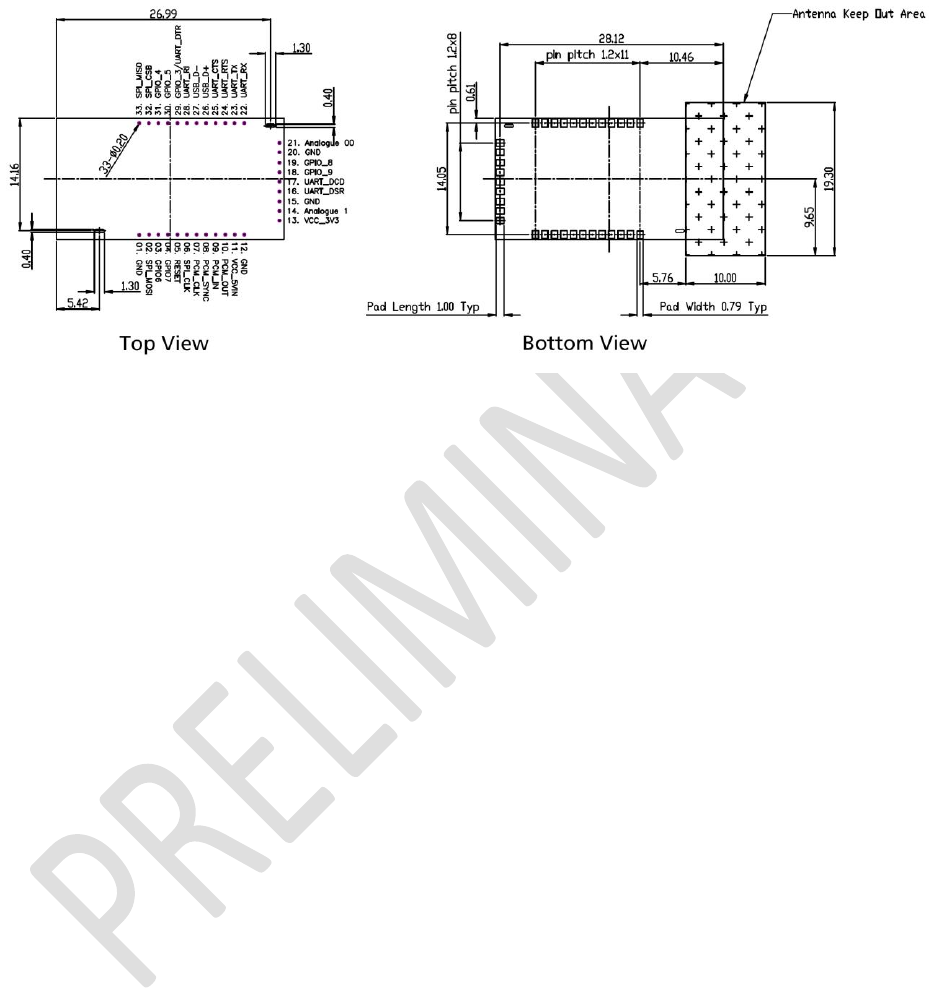
Enhanced Class 1 Bluetooth v2.1 Module
User’s Guide
Americas: +1-800-492-2320 Option 2
Europe: +44-1628-858-940
Hong Kong: +852-2923-0610
www.lairdtech.com/wireless
193
CONN-GUIDE-BT740_v0.2
18.3 BT740 Pad Definitions – Mechanical Drawing
Figure 18-3: Pad definitions mechanical drawing

Enhanced Class 1 Bluetooth v2.1 Module
User’s Guide
Americas: +1-800-492-2320 Option 2
Europe: +44-1628-858-940
Hong Kong: +852-2923-0610
www.lairdtech.com/wireless
194
CONN-GUIDE-BT740_v0.2
19 ORDERING INFORMATION
Part Number
Description
BT740-SA
Enhanced Class 1 Bluetooth V2.1 Module (internal antenna)
BT740-SC
Enhanced Class 1 Bluetooth v2.1 Module (uFL for external
antenna)
DVK – BT740-SA
Development board with BT740-SA module soldered in place
DVK – BT740-SC
Development board with BT740-SC module soldered in place
19.1 General Comments
This is a preliminary datasheet. Please check with Laird for the latest information before commencing a
design. If in doubt, ask.
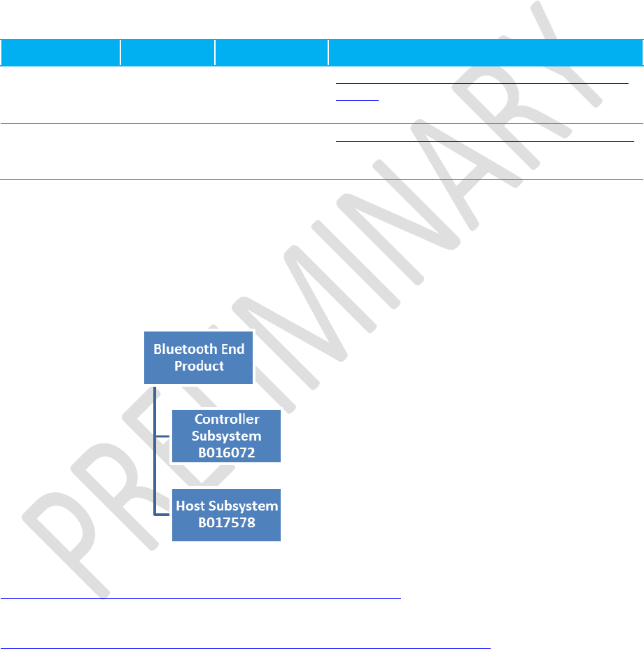
Enhanced Class 1 Bluetooth v2.1 Module
User’s Guide
Americas: +1-800-492-2320 Option 2
Europe: +44-1628-858-940
Hong Kong: +852-2923-0610
www.lairdtech.com/wireless
195
CONN-GUIDE-BT740_v0.2
20 BLUETOOTH SIG APPROVALS
20.1 Subsystem Combinations
This section covers the procedure for generating a new EPL (End Product Listing) on the Bluetooth SIG
website. In the instance of subsystems, a member can combine two or more subsystems to create a
complete Bluetooth end product.
Subsystem listings referenced as an example:
Design Name
Owner
QDID number
Link to listing on the SIG website
BT740-Sx
Laird
B0xxxx
https://www.bluetooth.org/tpg/QLI_viewQDL.cfm?qid
=16072
Interface
Express
Subsystem
Cambridge
Consultants
Limited
B017578
http://bluetooth.org/tpg/QLI_viewQDL.cfm?qid=17578
20.1.1 Assumptions
This procedure assumes that the member is simply combining two subsystems to create a complete end
product. This is achieved by using the EPL interface on the Bluetooth SIG website. The following diagram
shows the basic subsystem combination of a controller and host subsystem. The controller provides the
RF/BB/LM and HCI layers, with the host providing L2CAP, SDP, GAP, RFCOMM/SPP, and any other
specific protocols and profiles existing in the host subsystem listing.
The following link provides an overview of the EPL system:
https://www.bluetooth.org/technical/qualification/eploverview.htm
For a detailed procedure of how to make an EPL entry, please refer to the following SIG document:
https://www.bluetooth.org/docman/handlers/DownloadDoc.ashx?doc_id=71880
In the case of the Laird and Cambridge Consultants Limited subsystem combination, please search for
QDID B016072 in step 4 and then ‘Create New EPL’ as per step 5. Under step 7, enter QDID B017578 in
the box ‘Link additional QDLs’.

Enhanced Class 1 Bluetooth v2.1 Module
User’s Guide
Americas: +1-800-492-2320 Option 2
Europe: +44-1628-858-940
Hong Kong: +852-2923-0610
www.lairdtech.com/wireless
196
CONN-GUIDE-BT740_v0.2
Note: Alternatively, the member can choose to have a new QDID for the subsystem combination.
However, note that this incurs a listing fee and requires the subsystem combination to be
assessed against the latest qualification requirements.
20.1.2 Useful FAQ links
https://www.bluetooth.org/ticketing/view_article.cfm?action=article_comment&aid=284
https://www.bluetooth.org/ticketing/view_article.cfm?action=article_comment&aid=300
https://www.bluetooth.org/ticketing/view_article.cfm?action=article_comment&aid=140
20.1.3 Additional Assistance
Please contact your local sales representative for further assistance

Enhanced Class 1 Bluetooth v2.1 Module
User’s Guide
Americas: +1-800-492-2320 Option 2
Europe: +44-1628-858-940
Hong Kong: +852-2923-0610
www.lairdtech.com/wireless
197
CONN-GUIDE-BT740_v0.2
21 GLOSSARY OF TERMS
Term
Description
A2DP
:
Advanced Audio Distribution Profile
ACL
:
Asynchronous Connection-Oriented Link
ADC
:
Analogue to Digital Converter
AGHFP
:
Audio Gateway Hands-Free Profile
AT
:
Command prefix, ‘Attention’
AVRCP
:
Audio/Video Remote Control Profile
BISM
:
Bluetooth Intelligent Serial Module
CoD
:
Class Of Device (also referred to as “device class”)
Codec
:
Device capable of encoding / decoding an analogue / digital signal
DAC
:
Digital to Analogue Converter
DSP
:
Digital Signal Processor
DUN
:
Dial-Up Network Profile
EIR
:
Extended Inquiry Response
eSCO
:
Enhanced Synchronous Connection Oriented Link (used for Audio)
FTP
:
File Transfer Profile
GOEP
:
Generic Object Access Exchange Profile
GPIO
:
General Purpose Input Output
HF
:
Hands-free Role of Hands-free Profile (“Hands-free Unit”)
HFG
:
Audio Gateway Role of Hands-free Profile (“Hands-free Gateway”)
HFP
:
Hands Free Profile
HID
:
Human Interface Device Profile
HS
:
Headset Role of Headset Profile (“Headset”)
HSG
:
Audio Gateway Role of Headset Profile (“Headset Gateway”)
HSP
:
Headset Profile
I/O (IO)
:
Input/Output
Mic
:
Microphone
MITM
:
Man In The Middle
OPP
:
Object Push Profile
PBAP
:
Phone Book Access Profile
PT
:
PASS THROUGH Command

Enhanced Class 1 Bluetooth v2.1 Module
User’s Guide
Americas: +1-800-492-2320 Option 2
Europe: +44-1628-858-940
Hong Kong: +852-2923-0610
www.lairdtech.com/wireless
198
CONN-GUIDE-BT740_v0.2
Term
Description
PWM
:
Pulse Width Modulation
SBC
:
Sub Band Codec
SCO
:
Synchronous Connection Oriented Link (used for Audio)
SLC
:
Service Level Connection
SPP
:
Serial Port Profile
SSO
:
Serial Stream Oriented
SSP
:
Secure Simple Pairing
SUI
:
SUBUNIT INFO Command
Sxxx
:
S-Register No. xxx
TDL
:
Trusted Device List
UART
:
Universal Asynchronous Receiver / Transmitter
UI
:
UNIT INFO Command

Enhanced Class 1 Bluetooth v2.1 Module
User’s Guide
Americas: +1-800-492-2320 Option 2
Europe: +44-1628-858-940
Hong Kong: +852-2923-0610
www.lairdtech.com/wireless
199
CONN-GUIDE-BT740_v0.2
Index
^^^ ........................................................................ 17
‘AT’ S Registers ................................................. 46
Abstract Data Model ........................................... 146
Agent Related AT Asynchronous Responses .... 157
Agent Related AT Commands............................ 154
Agent UART Traffic for Chart ............................. 131
Associate with Manager ..................................... 100
Associated ......................................................... 118
AT.. ...................................................................... 17
AT Commands and Responses ........................... 16
AT&F* .................................................................. 21
AT&F*AT* ............................................................ 22
AT&F*MP* ............................................................ 22
AT&F+ .................................................................. 21
AT+BTB+<string> ................................................ 23
AT+BTB=<string> ................................................ 22
AT+BTBnnnn ....................................................... 23
AT+BTD* .............................................................. 24
AT+BTD<bd_addr> .............................................. 24
AT+BTF<bd_addr> .............................................. 24
AT+BTG ............................................................... 24
AT+BTI ................................................................. 25
AT+BTIE .............................................................. 25
AT+BTIN .............................................................. 25
AT+BTIV .............................................................. 25
AT+BTK=<string> ................................................ 25
AT+BTKN ............................................................. 26
AT+BTKY ............................................................. 26
AT+BTN? ............................................................. 26
AT+BTN=<string> ................................................ 26
AT+BTP ............................................................... 27
AT+BTQ ............................................................... 27
AT+BTT? .............................................................. 27
AT+BTT<bd_addr> .............................................. 28
AT+BTTn? ............................................................ 28
AT+BTW<bd_addr> ............................................. 28
AT+BTX ............................................................... 29
AT+HAAhhhh ............................................... 29, 154
AT+HAB<bd_addr>,iiii.................................. 29, 155
AT+HADhhhh ............................................... 29, 155
AT+HAE,iiii,”endpointname” ................................. 30
AT+HAEiiii,”name” ............................................. 155
AT+HAGhhhh,aaaa,ssss.............................. 30, 155
AT+HAL ....................................................... 30, 156
AT+HARhhhh,pppp[,aaaa[,aaaa[…]]] .................. 30
AT+HAShhhh,aaaa,ssss,ddddd ........................... 31
AT+HAShhhh,aaaa,ssss,hhhhhhhhhhhh ........... 156
AT+HME,iiii,”endpointname” ................................ 31
AT+HMEiiii,”name” ............................................. 160
AT+HMGhhhh,oooo,aaaa ............................ 32, 160
AT+HML ....................................................... 31, 160
AT+HMThhhh, ccyymmddhhmmssaa ................ 161
AT+HMThhhh,ttttttt ............................................... 32
AT+KY<addr>,<link_key> .................................... 32

Enhanced Class 1 Bluetooth v2.1 Module
User’s Guide
Americas: +1-800-492-2320 Option 2
Europe: +44-1628-858-940
Hong Kong: +852-2923-0610
www.lairdtech.com/wireless
200
CONN-GUIDE-BT740_v0.2
AT+KY<addr>? .................................................... 32
ATA ...................................................................... 17
ATD<bd_addr>,<uuid> ......................................... 17
ATEn .................................................................... 18
ATH ...................................................................... 18
ATIn ..................................................................... 18
ATO ...................................................................... 20
ATSn?<$> ............................................................ 20
ATSn=? ................................................................ 21
ATSn=m ............................................................... 20
ATX<string> ......................................................... 21
Authentication and Encryption ........................... 165
Background ........................................................ 145
Bind Agent to a Manager ................................... 100
Blob Manage ........................................................ 95
BLOB Manager .................................................. 125
Command Packets ............................................... 52
Configuration Commands .................................... 63
Connection Commands ........................................ 65
Connection Events ............................................. 112
Connection Management ................................... 142
Connection Setup ............................................... 112
Create Endpoint in SDP Record........................... 98
Data Channel Numbers ........................................ 55
Data Channels ................................................... 120
Data Packets .................................................. 53, 55
Deassociated ..................................................... 118
Debug Events..................................................... 119
Debug Packet..................................................... 119
Default ‘S’ Registers ............................................. 65
Disassociate From Manager .............................. 109
Disconnect ......................................................... 113
Drop Connection .................................................. 68
Dropping Connections ........................................ 142
Enhanced Inquiry Data Packet Format ................ 73
Enhanced Inquiry Responses ............................ 168
Event Packets ...................................................... 54
Factory Default ..................................................... 92
Firmware Upgrade via UART ............................. 139
Flow control & Data Integrity ................................ 51
Get Connectable, Discoverable, Security Modes . 59
Get Digital/Analog I/O .......................................... 93
Get Local Friendly Name ..................................... 89
Get Open Channel List ......................................... 71
Get Remote Friendly Name ................................. 88
Get Security Mode ............................................... 87
Getting OUPUT Reports from a Host ................. 127
GPIO Access via SReg 619 and 620 ................. 167
GPIO Exchange via Rfcomm Modem Signalling 167
HDP Agent Model .............................................. 147
HDP Data Channels ........................................... 120
HDP Manager Model .......................................... 158
HDP Profile (Health Device Profile) .................... 145
HDP Profile Commands ....................................... 97
HDP Profile Related Events ............................... 118
HDP related S Registers ...................................... 98

Enhanced Class 1 Bluetooth v2.1 Module
User’s Guide
Americas: +1-800-492-2320 Option 2
Europe: +44-1628-858-940
Hong Kong: +852-2923-0610
www.lairdtech.com/wireless
201
CONN-GUIDE-BT740_v0.2
HDP Usage Message ......................................... 128
HDP: Endpoint Definitionin SDP Record .............. 31
HID Connections ................................................ 126
HID Descriptors .................................................. 144
HID Device Profile (HID) .................................... 143
Host Command/Responses ................................. 58
Host Packet Receive Flowchart ........................... 57
Host to Module Direction .................................... 120
Host to Module Packets ....................................... 52
IEEE ‘Black Box’ Model ...................................... 145
Incoming Connection ......................................... 112
Incoming Connections ........................................ 142
Incoming Pairing Procedure ................................. 78
Information ........................................................... 61
Information Commands ........................................ 58
Information Events ............................................. 110
Inquiry Commands ............................................... 72
Inquiry Events .................................................... 110
Inquiry Request .................................................... 72
Inquiry Result ..................................................... 110
Introduction to MultiPoint Protocol........................ 51
Invalid Packet Size ............................................. 111
Legacy Pairing ............................................. 78, 165
Link Key ............................................................. 114
Link Key Ex ........................................................ 115
Local Friendly Name .......................................... 116
Logical Packet Format ....................................... 121
Make Outgoing Connection .................................. 67
Malloc Statistics ................................................. 120
Manager Related AT Asynchronous Responses 161
Manager Related AT Commands ....................... 160
Manager UART Traffic for Chart ........................ 133
Message Sequence Chart .................................. 129
Miscellaneous Commands ................................... 87
Miscellaneous Events ........................................ 114
Modem Status .................................................... 114
Module Events ................................................... 110
Module to Host Direction .................................... 120
Module to Host Packets ....................................... 53
No Operation ........................................................ 58
Out of Band (OOB) Pairing ................................ 136
Packet Format ...................................................... 52
Packet Processing Logic ...................................... 53
Packet Type: Attribute Value .............................. 121
Packet Type: Scan Report ................................. 121
Pair Initiate ........................................................... 76
Pairing Commands ............................................... 75
Pin Code Request .............................................. 115
PinCode (Command) ........................................... 81
PinCode (Confirmation) ........................................ 82
Profiles ............................................................... 143
Protocol Activation ............................................... 16
Read ‘S’ Register ................................................. 63
Read Attribute Value .......................................... 106
Read Local Bluetooth Address ............................. 60
Read S Register’s Valid Range ............................ 21

Enhanced Class 1 Bluetooth v2.1 Module
User’s Guide
Americas: +1-800-492-2320 Option 2
Europe: +44-1628-858-940
Hong Kong: +852-2923-0610
www.lairdtech.com/wireless
202
CONN-GUIDE-BT740_v0.2
Read The Link Key For Address Specified .......... 32
Register SDP record ............................................ 99
Remote Friendly Name ...................................... 117
Reset .................................................................... 94
Response Packets ............................................... 54
RSSI and Link Quality .......................................... 70
Sample Host/Module Message Sequence ......... 163
Send Fixed Scan Report to Manager ................. 102
Send VAR Scan Report to Manager .................. 104
Sending INPUT Reports ..................................... 127
Serial Port Profile (SPP) ..................................... 143
Service Incoming Connection .............................. 66
Set Connectable Mode ......................................... 65
Set Date and Time ............................................. 108
Set Device Class .................................................. 91
Set Digital I/O ....................................................... 94
Set Discoverable Mode ........................................ 74
Set Local Friendly Name ...................................... 90
Set Modem Lines ................................................. 69
SIMPLE PAIRING Confirmation ........................... 81
Simple Secure Pairing ........................................ 165
Simple Secure Pairing ‘Display Only’ ............. 77, 79
Simple Secure Pairing ‘Display Yes/No’ ......... 77, 79
Simple Secure Pairing ‘Just Works’ ............... 76, 79
Simple Secure Pairing ‘Keyboard Only’ ......... 78, 80
Sniff Mode Explained ......................................... 134
Special S Registers (240 to 255).......................... 45
Specifying a Custom Hid Descriptor for Use ...... 127
Specifying Service Record Name for Custom Hid128
Standard S Registers ........................................... 35
Status ................................................................. 111
STATUS Values ................................................. 141
Store ‘S’ Registers ............................................... 64
The HCOMMAND & EVENT Values .................. 140
Throughput Analysis .......................................... 137
Time Update....................................................... 119
Trusted Database Add Key (Out-Of-Band Facilitator) ... 86
Trusted Database Change Type .......................... 85
Trusted Database Delete Record ......................... 84
Trusted Database Is Peer Trusted ....................... 86
Trusted Database Read Record........................... 84
Trusted Database Record Count.......................... 83
UART Host Power Saving Facility ...................... 135
UART Protocol Selection & Indication Via GPIO 139
Unknown Command ........................................... 110
Unsolicited/Async Responses .............................. 33
Uploading a HID Descriptor into the Module ...... 127
Weigh Scale Data Specialization ....... 148, 150, 152
Write ‘S’ Register ................................................. 64
Write Attribute Value .......................................... 107

Enhanced Class 1 Bluetooth v2.1 Module
User’s Guide
Americas: +1-800-492-2320 Option 2
Europe: +44-1628-858-940
Hong Kong: +852-2923-0610
www.lairdtech.com/wireless
203
CONN-GUIDE-BT740_v0.2
Smart Technology. Delivered.
Laird Ltd. is the world leader in the design and manufacture of customized,
performance-critical products for wireless and other advanced electronics applications.
Laird partners with its customers to find solutions for applications in various industries
such as:
Network Equipment
Telecommunications
Data Communications
Automotive Electronics
Computers
Aerospace
Military
Medical Equipment
Consumer Electronics
Laird offers its customers unique product solutions, dedication
to research and development, as well as a seamless network of
manufacturing and customer support facilities across the globe.
CONN-GUIDE-BT740_v0 2
Copyright © 2013 Laird, Inc. All rights reserved.
The information contained in this manual and the accompanying software programs are copyrighted and all rights
are reserved by Laird, Inc. Laird, Inc. reserves the right to make periodic modifications of this product without
obligation to notify any person or entity of such revision. Copying, duplicating, selling, or otherwise distributing any
part of this product or accompanying documentation/software without the prior consent of an authorized
representative of Laird, Inc. is strictly prohibited.
All brands and product names in this publication are registered trademarks or trademarks of their respective holders.
This material is preliminary
Information furnished by Laird in this specification is believed to be accurate. Devices sold by Laird are covered by
the warranty and patent indemnification provisions appearing in its Terms of Sale only. Laird makes no warranty,
express, statutory, and implied or by description, regarding the information set forth herein. Laird reserves the right
to change specifications at any time and without notice. Laird products are intended for use in normal commercial
and industrial applications. Applications requiring unusual environmental requirements such as military, medical life-
support or life-sustaining equipment are specifically not recommended without additional testing for such application.
Limited Warranty, Disclaimer, Limitation of Liability
globalsolutions: local support™
USA: +1.800.492.2320
Europe: +44.1628.858.940
Asia: +852.2923-0610
wireless.support@lairdtech.com
www.lairdtech.com/wireless