Laird Connectivity BT900 Bluetooth Dual Mode UART AT featuring smartBASIC User Manual BT900
Laird Technologies Bluetooth Dual Mode UART AT featuring smartBASIC BT900
UserManual.wiki
>
Laird Connectivity
>
BT900 User Manual
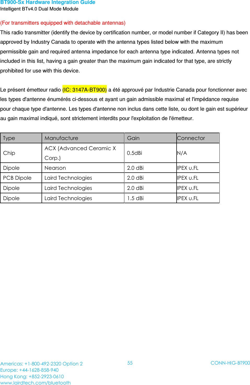
User manual
Navigation menu
Upload a User Manual
Namespaces
Wiki Guide
HTML
PDF
Info
Views
User Manual
Discussion / Help
Navigation