Laird Connectivity LX2400 LX2400-3, LX2400-10 and LX2400-150 User Manual exb22
AeroComm Corporation LX2400-3, LX2400-10 and LX2400-150 exb22
UserManual.wiki
>
Laird Connectivity
>
LX2400 User Manual
Revised manual please remove the other
Navigation menu
Upload a User Manual
Namespaces
Wiki Guide
HTML
PDF
Info
Views
User Manual
Discussion / Help
Navigation

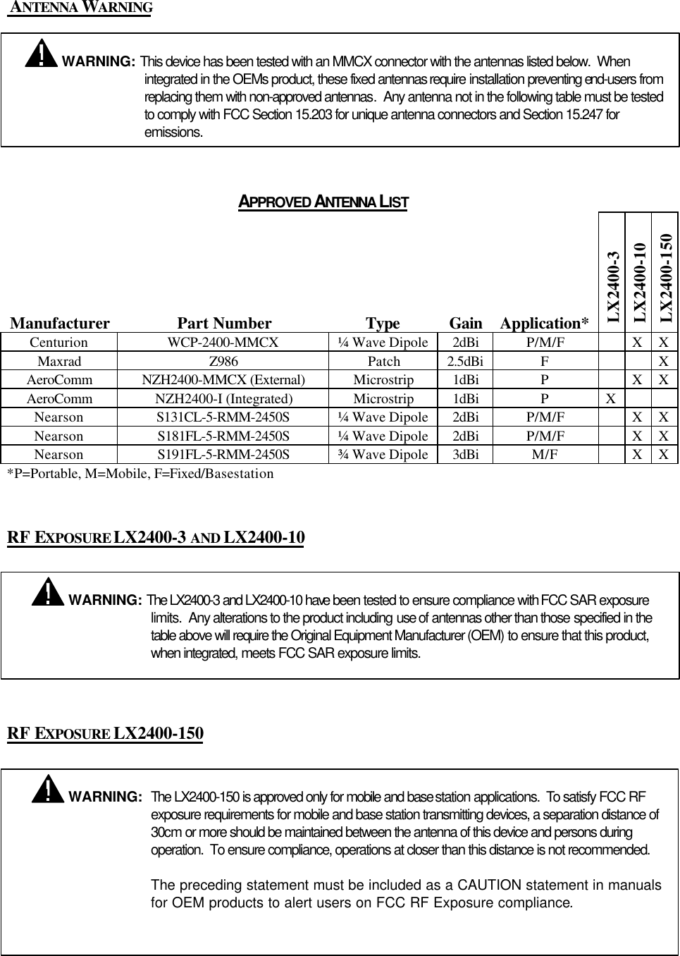
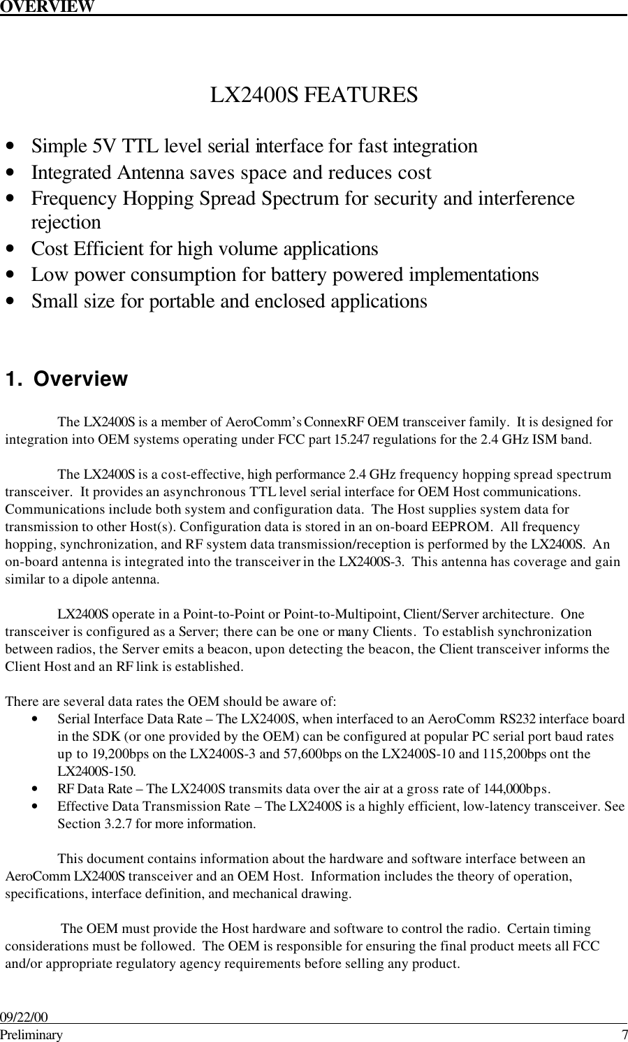
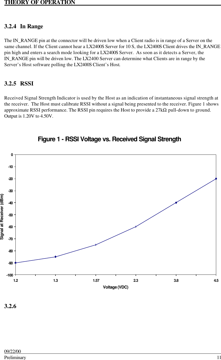
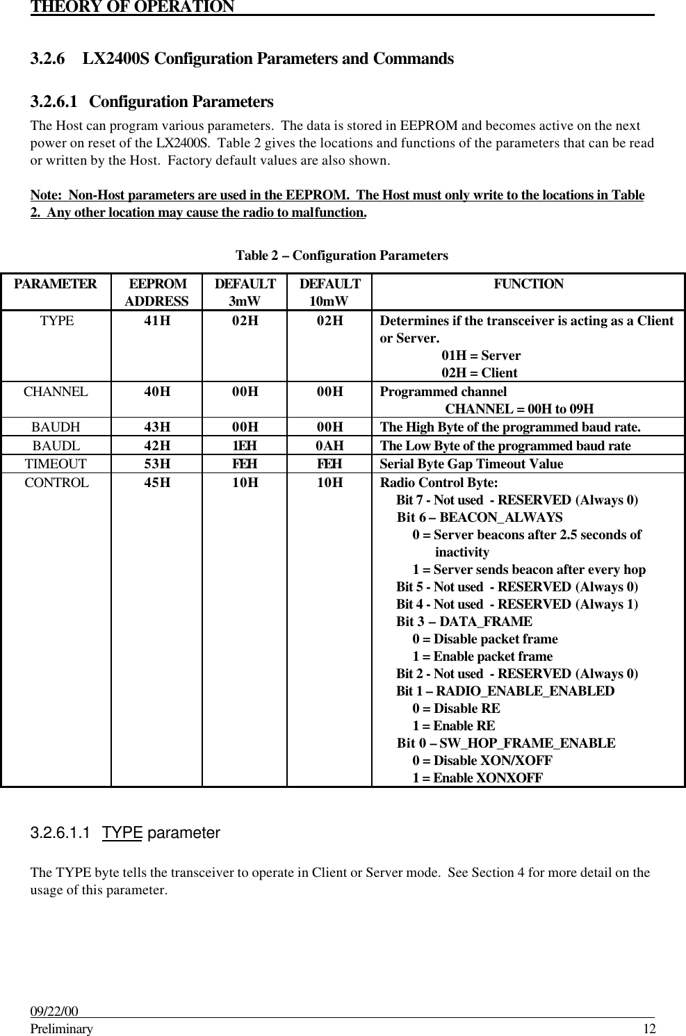
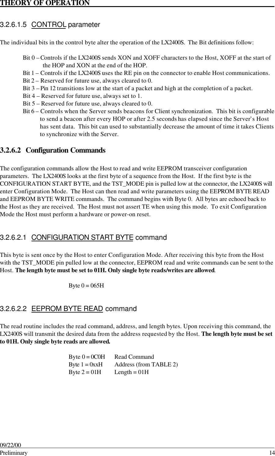
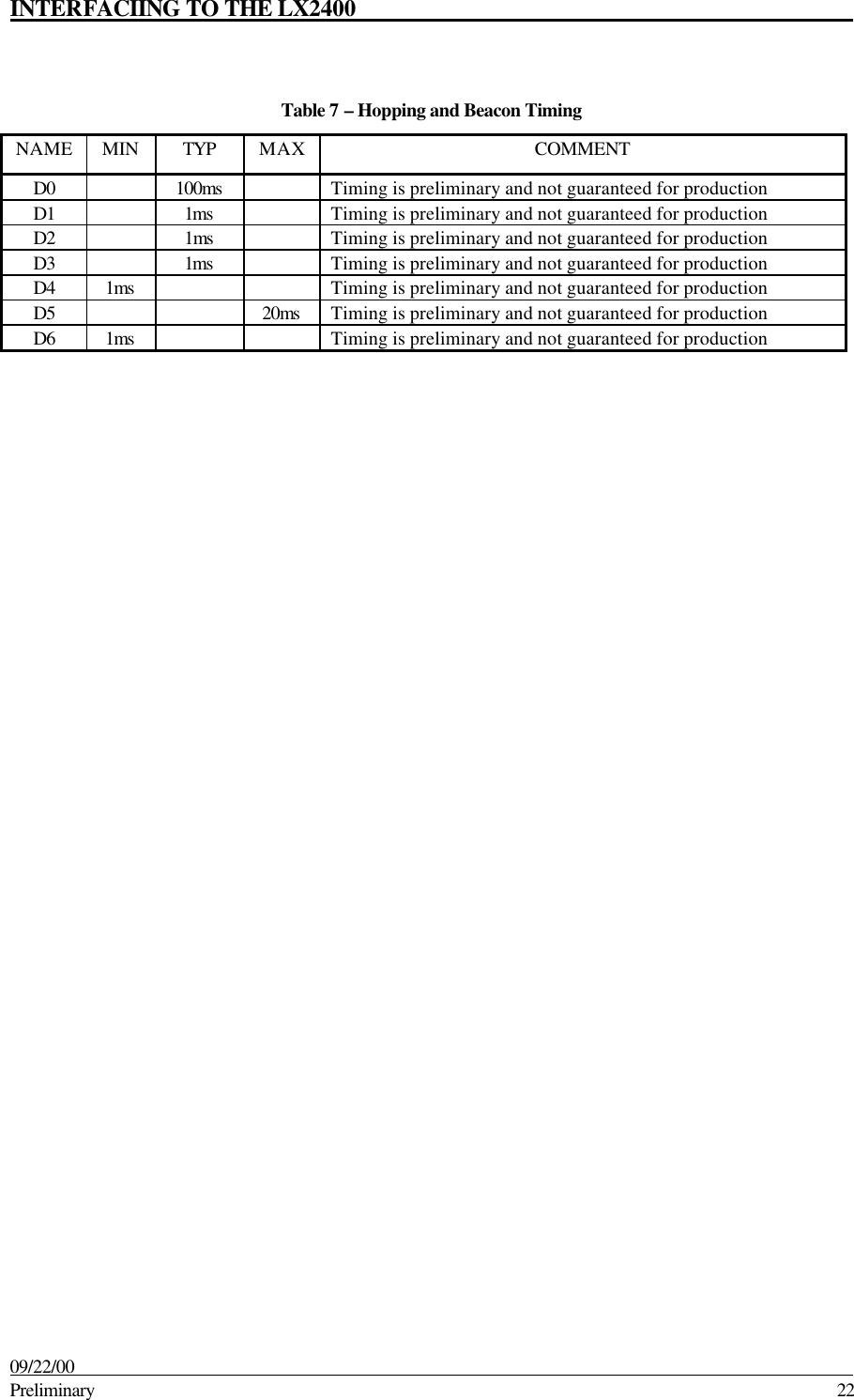
![THEORY OF OPERATION 09/22/00 Preliminary 133.2.6.1.2 CHANNEL parameterThe LX2400S can be programmed to one of ten different channels. Client mode transceivers will receive andtransmit to a Server on the same channel as programmed. Servers will receive and transmit to Clients on thesame channel as programmed. CHANNEL can be programmed with a value ranging from 0 to 9.3.2.6.1.3 BAUDRATE parameterThis two-byte value determines the baud rate used for communicating over the serial interface to theLX2400S. TABLE 3 lists values for some popular baud rates. Baud rates below 1200 are not supported.When programming a baud rate the Host must program the associated TIMEOUT value. This value is notused if the TST_MODE line on the connector is pulled low at reset. The baud rate will be forced to 9600.For Baud Rate values other than shown in Table 3, the following equations can be used:BAUD = (18.432E+06/(32*desired baud rate))BAUDH= High 8 bits of BAUD (base16)BAUDL = Low 8 bits of BAUD (base16)3.2.6.1.4 TIMEOUT parameterThe TIMEOUT value is the amount of time the LX2400S will allow between bytes when receiving serialbytes from the Host and receiving bytes on the RF link. It is equal to between two and four byte times.TIMEOUT can always be less than the value specified or calculated, but, never greater.Table 3 – Baud Rate/TimeoutBAUDRATE BAUDH BAUDL TIMEOUT57600*00H 0AH FDH38400*00H 0FH FCH28800*00H 14H FBH19200 00H 1EH F9H14400 00H 28H F7H9600 00H 3CH F3H4800 00H 78H E7H2400 00H F0H CEH1200 01H E0H 9CH* Not Available with LX2400S-3AFor Timeout values other than shown in Table 3, the following equations can be used:IBT = 10/desired baud rateTIMEOUT = (base16) High 8 bits of [2^16-(24/18.432E+06/IBT)]](https://usermanual.wiki/Laird-Connectivity/LX2400/User-Guide-118302-Page-13.png)