Laird Connectivity LX2400 LX2400-3, LX2400-10 and LX2400-150 User Manual exb22
AeroComm Corporation LX2400-3, LX2400-10 and LX2400-150 exb22
Revised manual please remove the other

LX2400S Transceiver
PRELIMINARY
Specifications Subject to Change
Hardware and Software
Interface Specification
Version 3.3
13256 W. 98th Street
Lenexa, KS 66215
(800) 492-2320
Fax (913) 492-1243
www.aerocomm.com
wireless@aerocomm.com
§§§§§§§§§§§§§§§§§§§§§§§§§§§§§§§§§§§§§§§§§§§§§§§§§§§§§§§§§§§§§§§§§§§§§§
Copyright Information/FCC User’s Notice
Copyright Copyright © 2000 AEROCOMM, Inc. All rights reserved.
Information The information contained in this manual and the accompanying
software programs are copyrighted and all rights are reserved by
AEROCOMM, Inc. AEROCOMM, Inc. reserves the right to make
periodic modifications of this product without obligation to notify
any person or entity of such revision. Copying, duplicating, selling,
or otherwise distributing any part of this product without the prior
consent of an authorized representative of AEROCOMM, Inc. is
prohibited.
All brands and product names in this publication are registered
trademarks or trademarks of their respective holders.
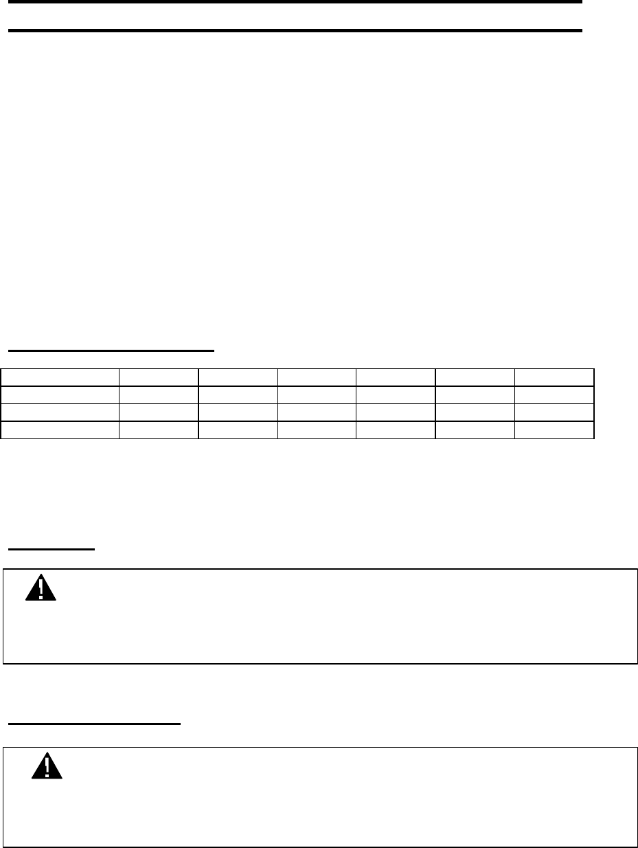
AGENCY APPROVAL OVERVIEW
US/FCC CAN/IC EUR/EN** Portable Mobile Fixed
LX2400-3 XXXXXX
LX2400-10 XXXXXX
LX2400-150 X X X-30cm X-30cm
** Does not include France and Spain
Note: The product approvals above are with antennas specified below.
FCC NOTICE
LABELING REQUIREMENTS
WARNING: This device complies with Part 15 of the FCC Rules. Operation is subject to the following two
conditions: (1) this device may not cause harmful interference and (2) this device must accept any
interference received, including interference that may cause undesired operation.
WARNING: The Original Equipment Manufacturer (OEM) must ensure that FCC labeling requirements are
met. This includes a clearly visible label on the outside of the OEM enclosure specifying
“Contains Transmitter Module FCC ID: KQL-LX2400”, as well as the FCC Notice above.
ANTENNA WARNING
APPROVED ANTENNA LIST
Manufacturer Part Number Type Gain Application*
LX2400-3
LX2400-10
LX2400-150
Centurion WCP-2400-MMCX ¼ Wave Dipole 2dBi P/M/F X X
Maxrad Z986 Patch 2.5dBi FX
AeroComm NZH2400-MMCX (External) Microstrip 1dBi PX X
AeroComm NZH2400-I (Integrated) Microstrip 1dBi PX
Nearson S131CL-5-RMM-2450S ¼ Wave Dipole 2dBi P/M/F X X
Nearson S181FL-5-RMM-2450S ¼ Wave Dipole 2dBi P/M/F X X
Nearson S191FL-5-RMM-2450S ¾ Wave Dipole 3dBi M/F X X
*P=Portable, M=Mobile, F=Fixed/Basestation
RF EXPOSURE LX2400-3 AND LX2400-10
RF EXPOSURE LX2400-150
WARNING: The LX2400-3 and LX2400-10 have been tested to ensure compliance with FCC SAR exposure
limits. Any alterations to the product including use of antennas other than those specified in the
table above will require the Original Equipment Manufacturer (OEM) to ensure that this product,
when integrated, meets FCC SAR exposure limits.
WARNING: This device has been tested with an MMCX connector with the antennas listed below. When
integrated in the OEMs product, these fixed antennas require installation preventing end-users from
replacing them with non-approved antennas. Any antenna not in the following table must be tested
to comply with FCC Section 15.203 for unique antenna connectors and Section 15.247 for
emissions.
WARNING: The LX2400-150 is approved only for mobile and base station applications. To satisfy FCC RF
exposure requirements for mobile and base station transmitting devices, a separation distance of
30cm or more should be maintained between the antenna of this device and persons during
operation. To ensure compliance, operations at closer than this distance is not recommended.
The preceding statement must be included as a CAUTION statement in manuals
for OEM products to alert users on FCC RF Exposure compliance.

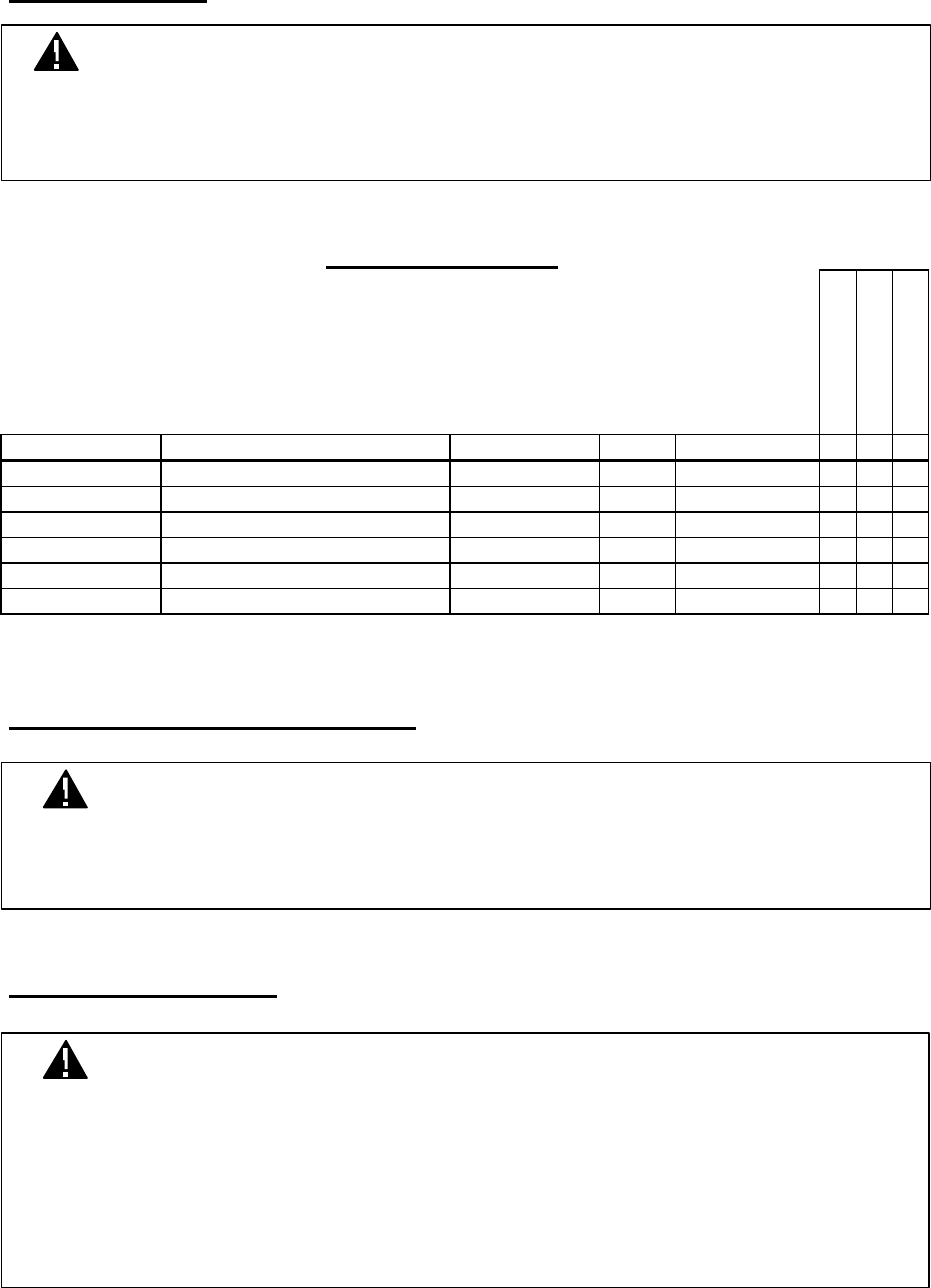
RF EXPOSURE OVERVIEW
SAR
Specifications
with Body
Tissue
(W/Kg)
MinimumR
F Exposure
Distance
(cm)
Antenna
Manufacturer Part Number Type Gain Applicatio
n*
LX2400-3
LX2400-10
LX2400-150
Centurion WCP-2400-MMCX ¼ Wave
Dipole
2dBi P/M/F N/A 0.400 30
Maxrad MC2400 Patch 2.5dBi FN/A N/A 30
AeroComm NZH2400-MMCX (External) Microstrip 1dBi PN/A 0.308 30
AeroComm NZH2400-I (Integrated) Microstrip 1dBi P0.057 N/A N/A
Nearson S131CL-5-RMM-2450S ¼ Wave
Dipole
2dBi P/M/F N/A 0.265 30
Nearson S181FL-5-RMM-2450S ¼ Wave
Dipole
2dBi P/M/F N/A 0.189 30
Nearson S191FL-5-RMM-2450S ¾ Wave
Dipole
3dBi M/F N/A 0.118 30
*P=Portable, M=Mobile, F=Fixed/Basestation

Revisions Description
Version 1.0 Initial Release Version - 01/20/2000
Version 2.0 Not Released
Version 3.0 Release Version - 2/15/2000
Full Document Update – major changes:
1. The Transmit Sync byte has been changed
2. The previous version called out RTS rather than TE for the Transmit Enable
pin. This has been corrected
Version 3.1 Release Version - 5/23/2000
1. Corrected Serial Interface data rate to 57,600bps maximum
2. Add specifications on LX2400S-10 and LX2400S-10A
3. Add ordering information
Version 3.2 Release Version - 8/1/2000
1. Corrected RF data rate to 144,000bps maximum
2. Corrected Frequency band to 2.402GHz – 2.478GHz
3. Added new column to Table 2. Now shows 3mW & 10mW defaults
4. Corrected hop time from 120ms to 100ms
5. Added current consumptions specifications for LX2400S-10(A)
6. Changed Input Voltage tolerance from 5% to 2%
7. Updated Table 2 with new Control Bit definitions
8. Updated Section 3.2.6.1.5 to include Control Bit definitions
9. Updated FCC section.
Version 3.3 Release Version - 9/14/2000
1. Update approved antenna table and Agency Requirements
2. Correct product and developer kit part numbers
Copyright © 2000
AeroComm, Inc.
This material is preliminary.
Information furnished by AeroComm in this specification is believed to be accurate. Devices sold by
AeroComm are covered by the warranty and patent indemnification provisions appearing in its Terms of
Sale only. AeroComm makes no warranty, express, statutory, and implied or by description, regarding the
information set forth herein. AeroComm reserves the right to change specifications at any time and without
notice.
AeroComm’s products are intended for use in normal commercial applications. Applications requiring
extended temperature range or unusual environmental requirements such as military, medical life-support or
life-sustaining equipment are specifically not recommended without additional testing for such application.

CONTENTS
09/22/00
Preliminary 6
TABLE OF CONTENTS
1. OVERVIEW .............................................................................................................................................................7
2. LX2400S SPECIFICATIONS ..............................................................................................................................8
3. THEORY OF OPERATION..................................................................................................................................9
3.1 INTERFACE SIGNAL DEFINITION..................................................................................................................9
3.2 HOST SOFTWARE/HARDWARE INTERFACE DEFINITION.......................................................................10
3.2.1 Host Transmit Frame Format...........................................................................................................10
3.2.2 Host Receive Frame Format..............................................................................................................10
3.2.3 Hopping Status....................................................................................................................................10
3.2.4 In Range................................................................................................................................................11
3.2.5 RSSI.......................................................................................................................................................11
3.2.6 LX2400S Configuration Parameters and Commands..................................................................12
3.2.7 Data Rates............................................................................................................................................15
4. INTERFACING TO THE LX2400S...................................................................................................................18
4.1 OPERATING MODES ...................................................................................................................................18
4.1.1 RECEIVE MODE.................................................................................................................................18
4.1.2 TRANSMIT MODE ..............................................................................................................................18
4.1.3 CONFIGURATION MODE.................................................................................................................19
4.1.4 HOPPING MODE................................................................................................................................19
4.1.5 BEACON MODE..................................................................................................................................19
4.2 LX2400S GLOBAL TIMING PARAMETERS.................................................................................................20
4.3 LX2400S TRANSMIT MODE TIMING..........................................................................................................20
4.4 LX2400S CONFIGUATION MODE TIMING.................................................................................................21
4.5 LX2400S HOPPING AND BEACON TIMING.................................................................................................21
5. MECHANICAL OVERVIEW ..............................................................................................................................23
5.1 TRANSCEIVER.................................................................................................................................................23
5.2 ANTENNA.......................................................................................................................................................23
6. ORDERING INFORMATION.............................................................................................................................24
6.1 PRODUCT PART NUMBERS...........................................................................................................................24
6.2 DEVELOPER KIT PART NUMBERS..............................................................................................................24
TABLES
Table 1 – Connector J1 Pin Definitions......................................................................................................................9
Table 2 – Configuration Parameters.........................................................................................................................12
Table 3 – Baud Rate/Timeout......................................................................................................................................13
Table 4 – Global Timing Parameters.........................................................................................................................20
Table 5 – Transmit Mode Timing...............................................................................................................................20
Table 6 – Configuration Mode Timing ......................................................................................................................21
Table 7 – Hopping and Beacon Timing......................................................................................................................22

OVERVIEW
09/22/00
Preliminary 7
LX2400S FEATURES
• Simple 5V TTL level serial interface for fast integration
• Integrated Antenna saves space and reduces cost
• Frequency Hopping Spread Spectrum for security and interference
rejection
• Cost Efficient for high volume applications
• Low power consumption for battery powered implementations
• Small size for portable and enclosed applications
1. Overview
The LX2400S is a member of AeroComm’s ConnexRF OEM transceiver family. It is designed for
integration into OEM systems operating under FCC part 15.247 regulations for the 2.4 GHz ISM band.
The LX2400S is a cost-effective, high performance 2.4 GHz frequency hopping spread spectrum
transceiver. It provides an asynchronous TTL level serial interface for OEM Host communications.
Communications include both system and configuration data. The Host supplies system data for
transmission to other Host(s). Configuration data is stored in an on-board EEPROM. All frequency
hopping, synchronization, and RF system data transmission/reception is performed by the LX2400S. An
on-board antenna is integrated into the transceiver in the LX2400S-3. This antenna has coverage and gain
similar to a dipole antenna.
LX2400S operate in a Point-to-Point or Point-to-Multipoint, Client/Server architecture. One
transceiver is configured as a Server; there can be one or many Clients. To establish synchronization
between radios, the Server emits a beacon, upon detecting the beacon, the Client transceiver informs the
Client Host and an RF link is established.
There are several data rates the OEM should be aware of:
• Serial Interface Data Rate – The LX2400S, when interfaced to an AeroComm RS232 interface board
in the SDK (or one provided by the OEM) can be configured at popular PC serial port baud rates
up to 19,200bps on the LX2400S-3 and 57,600bps on the LX2400S-10 and 115,200bps ont the
LX2400S-150.
• RF Data Rate – The LX2400S transmits data over the air at a gross rate of 144,000bps.
• Effective Data Transmission Rate – The LX2400S is a highly efficient, low-latency transceiver. See
Section 3.2.7 for more information.
This document contains information about the hardware and software interface between an
AeroComm LX2400S transceiver and an OEM Host. Information includes the theory of operation,
specifications, interface definition, and mechanical drawing.
The OEM must provide the Host hardware and software to control the radio. Certain timing
considerations must be followed. The OEM is responsible for ensuring the final product meets all FCC
and/or appropriate regulatory agency requirements before selling any product.

SPECIFICATIONS
09/22/00
Preliminary 8
2. LX2400S Specifications
GENERAL
Interface 20 pin mini-connector, See mechanical drawing.
Serial Interface Data Rate (See 3.2.6.1.3 & 3.2.6.1.4) LX2400S-3A, PC Baud rates up to 19,200bps
LX2400S-10, PC Baud rates up to 57,600bps
LX2400S-150, PC Baud rates up to 115,200bps
Power Consumption
Transmit/Receive
LX2400S-3A, 100mA/80mA typical
LX2400S-10, 115mA/115mA typical
LX2400S-150, 400mA/115mA typical
Channels (used to create independent networks) 10
Security Host Defined
RADIO
Frequency Band 2.402 – 2.478 GHz
Radio Type Spread Spectrum Frequency Hopping
Output Power (Conducted, no antenna) LX2400S-3A, 2.5mW typical
LX2400S-10, 11.0mW typical
LX2400S-150, 147.9mW typical
Effective Radiated Isotropic Power (EIRP with
Highest Gain Antenna)
LX2400S-3A, 3.1mW typical
LX2400S-10, 25.1mW typical
LX2400S-150, 288.4mW typical
Voltage 5V nominal +2%, + 50mV ripple
Sensitivity -90dBm typical
RF Data Rate 144Kbps
Range LX2400S-3A, Indoors to 100 ft., Outdoors to 500 ft.
LX2400S-10, Indoors to 300 ft., Outdoors to 3000 ft.
LX2400S-150, Indoors to 500 ft., Outdoors to 5000 ft.
PLL Lock Time 500 us typical
ENVIRONMENTAL
Temperature (Operating) 0 °C to +70 °C
Temperature (Storage) -50 °C to +85 °C
Humidity (non-condensing) 10% to 90%
PHYSICAL
Dimensions 1.65” x 2.65” x 0.20”
Antenna LX2400S-3A, Integrated dipole
LX2400S-10, MMCX Jack
LX2400S-150, MMCX Jack
Weight Less than 0.5 ounce

THEORY OF OPERATION
09/22/00
Preliminary 9
3. Theory of Operation
3.1 Interface Signal Definition
The LX2400S has a simple interface that allows OEM Host communications with the transceiver. Table 1
shows the connector pin numbers and associated functions. The I/O direction is also shown. The direction
is with regard to the transceiver. All I/O is 5Vdc TTL level signals except for RSSI. All outputs are weakly
pulled high (20k – 50k ohms) when left unconnected and are driven high at reset.
Table 1 – Connector J1 Pin Definitions
Pin TYPE Signal Name Function
1ODCD Not Implemented
2OTXD Transmitted data out of the transceiver
3IRXD Data input to the transceiver
4IDTR Not Implemented
5GND GND Signal Ground
6ODSR HOP FRAME/Data Set Ready – Active Low when the transceiver is
hopping.
7OCTS Clear to Send – Active Low when the transceiver is ready to accept data
for transmission. This is in response to a valid TE signal. A Client will not
respond with CTS if it is not in range of a Server.
8IRTS Not Implemented
9ORI Not Implemented
10 PWR VCC 5V + 2%
11 PWR VCC 5V + 2%
12 ITST_MODE Test Mode
1. When pulled low before applying power the transceiver’s serial
interface is forced to a 9600,8,N, 1 rate.
2. When pulled low and the CONFIGURATION START BYTE
command (See 3.2.6.2.1) is sent to the transceiver, Configuration
Mode is entered to read and write parameters in EEPROM
13 ORSSI Received Signal Strength - An analog output giving a relative indication of
received signal strength while in RECEIVE MODE.
14 IWR_ENA EEPROM Write Enable – When pulled low it allows the Host to write the
on-board EEPROM.
15 IUP_RESET RESET – Controlled by the LX2400S for power-on reset if left
unconnected. After a Stable power-on (4ms ) A 10us high pulse will reset
the LX2400S.
16 GND GND Signal Ground
17 ITE Transmit Enable – When pulled low, the transceiver switches to transmit
mode and will respond with CTS when data can be transmitted by the
Host.
18 IRE Radio Enable – When the RADIO_ENABLE_ENABLED control bit is set
in EEPROM the transceiver will only allow Host communications/control
when this line is pulled low. If the RADIO_ENABLE_ENABLED control
bit is cleared, the transceiver ignores this input.
19 OPLL_LOCK Factory Use Only – NC
20 OIN_RANGE In Range – Active Low when a Client radio is in range of a Server on the
same channel.
I = Input to the transceiver
O = Output from the transceiver

THEORY OF OPERATION
09/22/00
Preliminary 10
3.2 Host Software/Hardware Interface Definition
3.2.1 Host Transmit Frame Format
The LX2400S requires the following format in order to transmit a Host’s data packet over the RF link. The
frame consists of 3 bytes of preamble, 1 sync byte, a 16-bit length, and user data.
Byte 0 – 055H – preamble
Byte 1 – 055H – preamble
Byte 2 – 055H – preamble
Byte 3 – 03AH – sync
Byte 4 – Length High (bits 15-8)
Byte 5 – Length Low (bits 7-0)
Byte 6 – First byte Host Data
Byte n – Last byte Host Data
Length High/Length Low is a 16-bit length value that represents the length of bytes 6 through n inclusive.
Both byte and packet gap times must be followed as specified in Table 4. The maximum transmit time is
20ms. The maximum length depends on the Host’s Byte and Byte-Gap timing.
3.2.2 Host Receive Frame Format
The LX2400S transmits received RF data, beginning with the Length Bytes, to the Host following the
reception of a valid preamble. The preamble and the sync bytes are not transmitted to the Host.
Byte 0 – Length High
Byte 1 – Length Low
Byte 2 - First byte Host Data
Byte n – Last byte of Host Data
3.2.3 Hopping Status
If the SW_HOP_FRAME_ENABLE bit is set in EEPROM, The LX2400S sends an XOFF character to the
Host when it is ready to hop. Following the completion of the hop, the LX2400S sends an XON character to
inform the Host that the hop is completed. The Host must parse these bytes and assume if transmitting a
packet, the data did not reach the destination(s) and re-transmit the packet.
XOFF = 0E2H Transmitted at the start of a frequency hop.
XON = 0ACH Transmitted at the completion of a frequency hop.
The Host can also detect hopping status by monitoring the DSR pin on the connector. The DSR pin is
always enabled.
THEORY OF OPERATION
09/22/00
Preliminary 11
3.2.4 In Range
The IN_RANGE pin at the connector will be driven low when a Client radio is in range of a Server on the
same channel. If the Client cannot hear a LX2400S Server for 10 S, the LX2400S Client drives the IN_RANGE
pin high and enters a search mode looking for a LX2400S Server. As soon as it detects a Server, the
IN_RANGE pin will be driven low. The LX2400 Server can determine what Clients are in range by the
Server’s Host software polling the LX2400S Client’s Host.
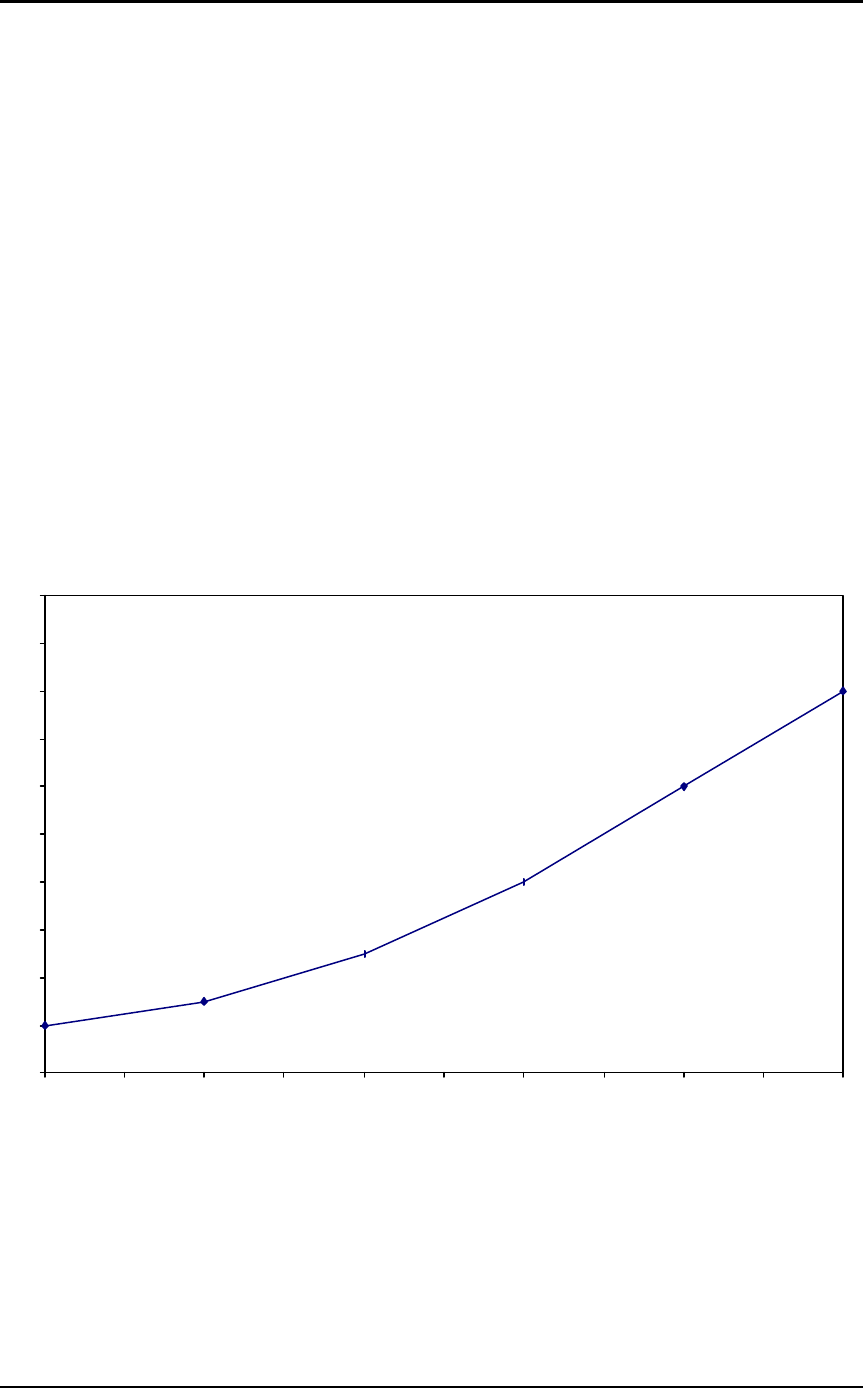
3.2.5 RSSI
Received Signal Strength Indicator is used by the Host as an indication of instantaneous signal strength at
the receiver. The Host must calibrate RSSI without a signal being presented to the receiver. Figure 1 shows
approximate RSSI performance. The RSSI pin requires the Host to provide a 27kΩ pull-down to ground.
Output is 1.20V to 4.50V.
3.2.6
Figure 1 - RSSI Voltage vs. Received Signal Strength
-100
-90
-80
-70
-60
-50
-40
-30
-20
-10
0
1.2 1.3 1.57 2.3 3.8 4.5
Voltage (VDC)
Signal at Receiver (dBm)

THEORY OF OPERATION
09/22/00
Preliminary 12
3.2.6 LX2400S Configuration Parameters and Commands
3.2.6.1 Configuration Parameters
The Host can program various parameters. The data is stored in EEPROM and becomes active on the next
power on reset of the LX2400S. Table 2 gives the locations and functions of the parameters that can be read
or written by the Host. Factory default values are also shown.
Note: Non-Host parameters are used in the EEPROM. The Host must only write to the locations in Table
2. Any other location may cause the radio to malfunction.
Table 2 – Configuration Parameters
PARAMETER EEPROM
ADDRESS DEFAULT
3mW DEFAULT
10mW FUNCTION
TYPE 41H 02H 02H Determines if the transceiver is acting as a Client
or Server.
01H = Server
02H = Client
CHANNEL 40H 00H 00H Programmed channel
CHANNEL = 00H to 09H
BAUDH 43H 00H 00H The High Byte of the programmed baud rate.
BAUDL 42H 1EH 0AHThe Low Byte of the programmed baud rate
TIMEOUT 53H FEH FEH Serial Byte Gap Timeout Value
CONTROL 45H 10H 10H Radio Control Byte:
Bit 7 - Not used - RESERVED (Always 0)
Bit 6 – BEACON_ALWAYS
0 = Server beacons after 2.5 seconds of
inactivity
1 = Server sends beacon after every hop
Bit 5 - Not used - RESERVED (Always 0)
Bit 4 - Not used - RESERVED (Always 1)
Bit 3 – DATA_FRAME
0 = Disable packet frame
1 = Enable packet frame
Bit 2 - Not used - RESERVED (Always 0)
Bit 1 – RADIO_ENABLE_ENABLED
0 = Disable RE
1 = Enable RE
Bit 0 – SW_HOP_FRAME_ENABLE
0 = Disable XON/XOFF
1 = Enable XONXOFF
3.2.6.1.1 TYPE parameter
The TYPE byte tells the transceiver to operate in Client or Server mode. See Section 4 for more detail on the
usage of this parameter.

THEORY OF OPERATION
09/22/00
Preliminary 13
3.2.6.1.2 CHANNEL parameter
The LX2400S can be programmed to one of ten different channels. Client mode transceivers will receive and
transmit to a Server on the same channel as programmed. Servers will receive and transmit to Clients on the
same channel as programmed. CHANNEL can be programmed with a value ranging from 0 to 9.
3.2.6.1.3 BAUDRATE parameter
This two-byte value determines the baud rate used for communicating over the serial interface to the
LX2400S. TABLE 3 lists values for some popular baud rates. Baud rates below 1200 are not supported.
When programming a baud rate the Host must program the associated TIMEOUT value. This value is not
used if the TST_MODE line on the connector is pulled low at reset. The baud rate will be forced to 9600.
For Baud Rate values other than shown in Table 3, the following equations can be used:
BAUD = (18.432E+06/(32*desired baud rate))
BAUDH= High 8 bits of BAUD (base16)
BAUDL = Low 8 bits of BAUD (base16)
3.2.6.1.4 TIMEOUT parameter
The TIMEOUT value is the amount of time the LX2400S will allow between bytes when receiving serial
bytes from the Host and receiving bytes on the RF link. It is equal to between two and four byte times.
TIMEOUT can always be less than the value specified or calculated, but, never greater.
Table 3 – Baud Rate/Timeout
BAUDRATE BAUDH BAUDL TIMEOUT
57600*00H 0AH FDH
38400*00H 0FH FCH
28800*00H 14H FBH
19200 00H 1EH F9H
14400 00H 28H F7H
9600 00H 3CH F3H
4800 00H 78H E7H
2400 00H F0H CEH
1200 01H E0H 9CH
* Not Available with LX2400S-3A
For Timeout values other than shown in Table 3, the following equations can be used:
IBT = 10/desired baud rate
TIMEOUT = (base16) High 8 bits of [2^16-(24/18.432E+06/IBT)]

THEORY OF OPERATION
09/22/00
Preliminary 14
3.2.6.1.5 CONTROL parameter
The individual bits in the control byte alter the operation of the LX2400S. The Bit definitions follow:
Bit 0 – Controls if the LX2400S sends XON and XOFF characters to the Host, XOFF at the start of
the HOP and XON at the end of the HOP.
Bit 1 – Controls if the LX2400S uses the RE pin on the connector to enable Host communications.
Bit 2 – Reserved for future use, always cleared to 0.
Bit 3 – Pin 12 transitions low at the start of a packet and high at the completion of a packet.
Bit 4 – Reserved for future use, always set to 1.
Bit 5 – Reserved for future use, always cleared to 0.
Bit 6 – Controls when the Server sends beacons for Client synchronization. This bit is configurable
to send a beacon after every HOP or after 2.5 seconds has elapsed since the Server’s Host
has sent data. This bit can used to substantially decrease the amount of time it takes Clients
to synchronize with the Server.
3.2.6.2 Configuration Commands
The configuration commands allow the Host to read and write EEPROM transceiver configuration
parameters. The LX2400S looks at the first byte of a sequence from the Host. If the first byte is the
CONFIGURATION START BYTE, and the TST_MODE pin is pulled low at the connector, the LX2400S will
enter Configuration Mode. The Host can then read and write parameters using the EEPROM BYTE READ
and EEPROM BYTE WRITE commands. The command begins with Byte 0. All bytes are echoed back to
the Host as they are received. The Host must not assert TE when using this mode. To exit Configuration
Mode the Host must perform a hardware or power-on reset.
3.2.6.2.1 CONFIGURATION START BYTE command
This byte is sent once by the Host to enter Configuration Mode. After receiving this byte from the Host
with the TST_MODE pin pulled low at the connector, EEPROM read and write commands can be sent to the
Host. The length byte must be set to 01H. Only single byte reads/writes are allowed.
Byte 0 = 065H
3.2.6.2.2 EEPROM BYTE READ command
The read routine includes the read command, address, and length bytes. Upon receiving this command, the
LX2400S will transmit the desired data from the address requested by the Host. The length byte must be set
to 01H. Only single byte reads are allowed.
Byte 0 = 0C0H Read Command
Byte 1 = 0xxH Address (from TABLE 2)
Byte 2 = 01HLength = 01H

THEORY OF OPERATION
09/22/00
Preliminary 15
3.2.6.2.3 EEPROM BYTE WRITE command
The write routine includes the write command, address, length, and data bytes. Upon receiving this
command, the LX2400S will write the data byte to the address specified but will not echo it back to the Host
until the EEPROM write cycle is complete. The write can take as long as 10ms to complete. Following the
write cycle, the LX2400S will transmit the data byte to the Host. The WR_ENA on the connector must be
pulled low to enable the write prior to issuing this command or the write will not occur. The length byte must
be set to 01H. Only single byte writes are allowed.
Byte 0 = 0C1H WRITE Command
Byte 1 = 0xxH Address (from TABLE 2)
Byte 2 = 01HLength = 01H
Byte 3 = 0xxH Data
NOTE: The WR_ENA pin on the connector should only be pulled low before sending an EEPROM BYTE
WRITE command and must be held low until the data byte is echoed to the Host.
Data Rates
Various data rates, timings, and system architecture need to be considered when determining Overall System
Throughput in a RF data system. The Host controls the Serial Interface Data Rate. The LX2400S has a fixed
RF Data Rate. The Effective Data Transmission Rate is determined from both Host and LX2400S operation.
3.2.7.1 Serial Interface Data Rate
The Serial Interface Data Rate is programmable by the Host. This is the rate the Host and the LX2400S
communicate over the Serial bus. Typical values range from 1200bps to 57,600bps. The only supported
mode is asynchronous – 8-bit, No Parity, 1 Start Bit, and 1 Stop Bit.
3.2.7.2 RF Data Rate
The RF Data Rate is the rate the LX2400S transmits and receives over the RF link. It is fixed at 144,000bps, 8-
bit, Parity, 1 Start Bit, and 1 Stop Bit.

THEORY OF OPERATION
09/22/00
Preliminary 16
3.2.7.3 Effective Data Transmission Rate
The maximum Effective Data Transmission Rate (EDTR) is defined as the rate of one-way continuous
transmission of data packets sent by a Host. It includes the transmitter turn-on and turn-off delays, HOP
time, Host data byte timing and the number of bytes per packet sent by the Host. Beacon timing is not used
in this calculation -- since it is only transmitted when data has not been received by the LX2400S from the
Host for approximately 2.5 seconds. Data from the Host is transmitted on the RF link as it is received from
the Host assuming the system is in sync and the RE pin is in the active state (if enabled). The following
example illustrates the EDTR at 57,600bps assuming a 32-bit CRC is included with the Host system data
bytes.
EXAMPLE:
Example data packet:
NPSL = Number of Host preamble, sync and length bytes = 6
NHSD = Number of Host system data bytes = 192
NHED = Number of Host error detection bytes = 4
TXON* = Transmitter on delay = 1ms
TXOFF* = Transmitter off delay = 1ms
HTM* = Hop overhead in a 1 second period = 8.34ms
BAUDRATE = Serial Interface Baud Rate = 57,600bps
Calculations:
IBT = Interface byte time = 10/BAUDRATE = 0.174ms
IGT = Interface Byte gap time = 0
PKT = Packet time = (NPSL + NHSD + NHED) * (IBT +IGT) = 35.07ms
EDTR = (1-HTM) * NHSD/(TXON+TXOFF+PKT) = (1-0.00834) * 192/37.07E-03 = 5136 bytes per
second or 51360 bits per second.
Efficiency = (51360 /57600)*100 = 89%
*Timing is preliminary
3.2.7.4 Overall System Throughput
The maximum Overall System Throughput (OST) is related to the EDTR and the Host’s system
implementation. Typical systems implement an acknowledgement of received data. This can take the form of
either an immediate or delayed response (a response acknowledging many packets). In a polled system,
where the Server sends a packet to the Client Host and waits for data to be returned, the Server Host usually
does not require separate acknowledge packets because the returned data becomes the acknowledgement.
Other systems, which transmit non-critical or repeated data, may not use any form of acknowledgement.

THEORY OF OPERATION
09/22/00
Preliminary 17
The following examples give OST for 3 different systems and uses the values from the previous section.
Other systems are possible:
1 – POSITIVE ACK SYSTEM -- An acknowledgement response packet for each packet received.
Additional example data:
NHRD = Number of Host system response bytes = 3 (e.g. command and two address bytes)
Calculations:
PKT = Packet time = (NPSL + NHSD + NHED) * (IBT + IGT) = 35.07ms
RSPT = Response time = (NPSL + NHRD + NHED) * (IBT + IGT) = 2.26ms
OST = (1-HTM) * NHSD / (TXON+ PKT + TXOFF + TXON + RSPT + TXOFF) / NHSD =
(1-0.00834) * 192/41.33E-03 = 4607 bytes per second or 46070 bits per second.
Efficiency = (46070 /57600) *100 = 80%
2 – POLLED SYSTEM -- An acknowledgement response via returned Host data.
Additional example data:
NHSDServer = Number of Host system data bytes = 192
NHSDClient = Number of Host system data bytes = 192
Calculations:
PKT = Packet time = (NPSL + NHSD + NHED) * (IBT + IGT) = 35.07ms
OST = (1-HTM) * (NHSDServer + NHSDClient )/((TXON+TXOFF+PKT)*2) =
(1-0.00834) * 384/74.14E-03 = 5136 bytes per second or 51360 bits per second
Efficiency = (51360 /57600) *100 = 89%
3 – REPEATED DATA SYSTEM --No acknowledgement response.
OST = EDTR = 51360 bits per second
Efficiency = (51360 /57600)*100 = 89%
*Timing is preliminary

INTERFACIING TO THE LX2400
09/22/00
Preliminary 18
4. Interfacing to the LX2400S
4.1 OPERATING MODES
The LX2400S uses an 8-bit programmable asynchronous serial interface to communicate to a Host. The
interface uses one start bit, eight data bits, and one stop bit. Only the interface baud rate is programmable
by the Host.
A typical system consists of one LX2400S operating in Server Mode (LX2400S Server) communicating with
one or many LX2400S(s) operating in Client Mode (LX2400S Client). In this architecture, Clients
communicate with a single Server. Clients do not communicate with other Clients. Data transmitted by a
Server is received by all of the Clients that are in-range. The Server receives the data sent by the Client. All
protocol functions (retries, addressing, CRCs, etc.) are performed by the Host software. All frequency
hopping and synchronization is provided automatically by the LX2400S without Host intervention.
The Firmware in the LX2400S is operating in one of five modes. The Host can determine through hardware
and/or software what mode the LX2400S is operating in using the DSR pin or the software XON/XOFF data.
4.1.1 RECEIVE MODE
The LX2400S is in RECEIVE MODE, by default, when it is not in any other operating mode. While in this
mode, the LX2400S is looking for valid preamble and sync data bytes from a transmitter. When valid
preamble and sync bytes are detected, the LX2400S will transmit data received on the RF link to the Host
using the HOST RECEIVE FRAME FORMAT. A Client LX2400S will only accept data from its Host when
it is in-range of a valid LX2400S Server.
4.1.2 TRANSMIT MODE
The Host software initiates transmission of a data packet on the RF link by lowering TE, waiting for CTS to
go low, followed by sending the specified preambles bytes, sync byte, data length, and data. Both maximum
data byte gaps and packet times must be adhered to. At the end of the transmission TE must return to a
Logic Level High. After TE is taken high by the Host, the LX2400S will drive CTS high. This indicates the
LX2400S is returning to RECEIVE MODE. The Host software must perform MAC layer functions (retries,
addressing CRCs, etc.). If the Client LX2400S is not in-range of a LX2400S Server, TRANSMIT MODE
will not be entered. The Client LX2400S will not respond with CTS.
The following sequence transmits a packet on the RF link:
1. The Host drives the TE pin low.
2. The LX2400S responds by driving CTS low.
3. The Host sends serial bytes as specified in the HOST TRANSMIT FRAME FORMAT. The
LX2400S transmits the HOST TRANSMIT FRAME FORMAT on the RF link as it receives each
byte from the Host.
4. The Host drives TE high after the last byte is received by the LX2400S.
5. The LX2400S responds by driving CTS high and returns to RECEIVE MODE.

INTERFACIING TO THE LX2400
09/22/00
Preliminary 19
4.1.3 CONFIGURATION MODE
The CONFIGURATION MODE is used to read and write the EEPROM -- allowing the Host to set channels,
baud rates, etc. See TABLE 2. While in this mode the LX2400S will not receive any data over the RF link.
TE and CTS are not used.
The Host enters this mode with the following sequence:
1. The Host pulls the TST_MODE pin low.
2. The Host sends the CONFIGURATION START BYTE to the LX2400S.
3. The Host pulls the WR_ENA pin low if writing.
4. The Host sends the EEPROM BYTE READ or the EEPROM BYTE WRITE command.
5. The Host Repeat Steps 3 and 4 until done.
6. The Host drives pins TST_MODE and WR_ENA high.
7. The Host resets the LX2400S.
NOTE: The WR_ENA pin should not be permanently tied low as brownout conditions can corrupt EEPROM
data.
4.1.4 HOPPING MODE
The HOPPING MODE is controlled by the LX2400S. The LX2400S hops approximately every 100ms . During
this time, the LX2400S is changing the frequency it will use to transmit and receive. The LX2400S informs
the Host of the hop by asserting the DSR pin at the connector or by using the XON/XOFF received bytes if
enabled in the EEPROM in the sequence. The DSR pin will frame the hopping procedure. When the Host
software detects the hopping mode during a transmission of a packet, it can be assumed that the packet did
not reach it’s destination and the Host should re-send the packet.
4.1.5 BEACON MODE
Beacon mode applies to a LX2400S Server only. In order to synchronize the hopping of all LX2400Ss in a
system, the LX2400S Server will transmit beacon data consisting of system timing information at a periodic
rate. This occurs by default after transceiver reset and initialization. The beacon is transmitted once per
HOP time -- immediately after a HOP occurs. Beacons are not transmitted when the LX2400S Server is
transmitting data from the HOST over the RF link. If the LX2400S Server does not receive data for
approximately 2.5 seconds from the Server Host, the LX2400S Server will resume transmitting Beacons. This
provides continuous synchronization data for the LX2400S Clients. The beacon data is not transmitted or
available to either the Client or Server Host. The beacon takes approximately 2ms to complete. The LX2400S
indicates that it is executing a HOP with the DSR pin and a XON/XOFF sequence if enabled.
The Server Host can ignore the HOP if the Host software has retry capabilities or can tolerate non-
delivery of data. Empirical testing shows a 3 to 5 percent loss of data when ignoring the HOP indicators.
(See “LX2400S Hopping and Beacon Timing” in Section 4.5)
INTERFACIING TO THE LX2400
09/22/00
Preliminary 20
4.2 LX2400S GLOBAL Timing Parameters
Table 4 – Global Timing Parameters
Timing is preliminary and not guaranteed for production
NAME MIN TYP Max COMMENT
tRT TBD 1ms Receive to Transmit settling time – Transmit Off
tTR TBD 1ms Transmit to Receive settling time – Transmit Off
tTXMOD 20ms Longest amount of time to continuously send data
tPackG 1ms TX Packet Gap
tByteG 1 byte time Maximum Byte Gap
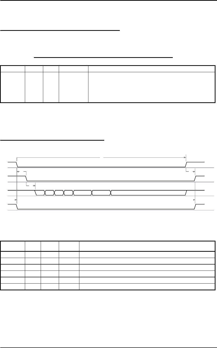
4.3 LX2400S Transmit Mode Timing
TE
CTS
RXD
RE
55 55 55 3A Length H Length L Host DataHost Data
D0
D1 D2
D3
D4 D5
*RE can be ignored if not enabled.
Table 5 – Transmit Mode Timing
NAME MIN TYP MAX COMMENT
D0 20ms Timing is preliminary and not guaranteed for production
D1 1ms Timing is preliminary and not guaranteed for production
D2 10us Timing is preliminary and not guaranteed for production
D3 0Timing is preliminary and not guaranteed for production
D4 0Timing is preliminary and not guaranteed for production
D5 0Timing is preliminary and not guaranteed for production
INTERFACIING TO THE LX2400
09/22/00
Preliminary 21
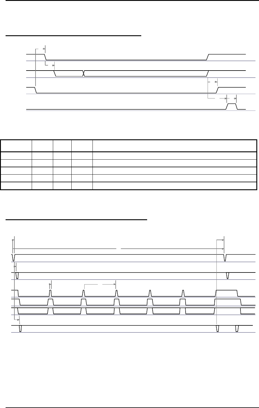
4.4 LX2400S Configuation Mode Timing
TST_MODE
RXD
WR_ENA
UP_RESET
65 EEPROM R/W CommandsEEPROM R/W Commands
D0
D1
D2
D3 D4
* WR_ENA is used only when writing to EEPROM
Table 6 – Configuration Mode Timing
NAME MIN TYP MAX COMMENT
D0 0Timing is preliminary and not guaranteed for production
D1 1ms Timing is preliminary and not guaranteed for production
D2 10ms When executing an EEPROM WRITE
D3 1ms Timing is preliminary and not guaranteed for production
D4 4ms Timing is preliminary and not guaranteed for production
4.5 LX2400S Hopping and Beacon Timing
DSR
RF_TXD
TE
CTS
RXD
TXD
HOST TX FRAME
D0
D1
D2
D3
D4
D5D6
XON XOFF
HOP HOP
XON
BEACON
BEACON
* Beacons are only transmitted if RXD has been idle for approximately 2.5 seconds.
* Diagram shows Host synchronous with the HOP.

INTERFACIING TO THE LX2400
09/22/00
Preliminary 22
Table 7 – Hopping and Beacon Timing
NAME MIN TYP MAX COMMENT
D0 100ms Timing is preliminary and not guaranteed for production
D1 1ms Timing is preliminary and not guaranteed for production
D2 1ms Timing is preliminary and not guaranteed for production
D3 1ms Timing is preliminary and not guaranteed for production
D4 1ms Timing is preliminary and not guaranteed for production
D5 20ms Timing is preliminary and not guaranteed for production
D6 1ms Timing is preliminary and not guaranteed for production
MECHANICAL
09/22/00
Preliminary 23
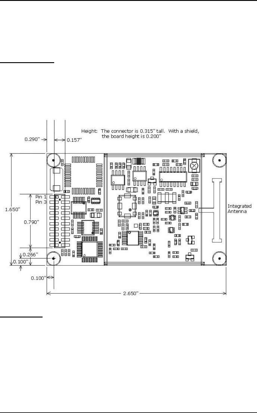
5. Mechanical Overview
5.1 Transceiver
The LX2400S measures 1.65” x 2.65”. Critical parameters are as follows:
J1 – 20 pin connector (lower left edge) SAMTEC TMM-110-01-L-D-SM
(4) Mounting holes are 0.100” diameter.
Figure 1. Mechanical Overview of LX2400S
5.2 Antenna
The LX2400S-3A and the LX2400S-10A incorporate an Aerocomm NZH antenna on the transceiver board.
The NZH is a highly efficient, microstrip, center-fed dipole design with a broad pattern. The NZH is
matched to the RF circuits yielding superior performance. This is important when using low-power RF
transceivers because a poor or marginally matched antenna will drastically reduce the operating distance
between transceivers. Special consideration must be given to the antenna placement in the OEM’s design.
Materials in close proximity (up to 4 inches) can affect antenna performance. Aerocomm can assist the OEM
with fine-tuning the antenna and/or enclosure that will incorporate the transceiver. Contact your AeroComm
OEM salesman or OEM customer support for assistance. The LX2400S-10 and LX2400-150 incorporate an
MMCX jack (Telegartner P/N J0134A0081) allowing the OEM to select antennas with specific
characteristics.

ORDERING INFORMATION
09/22/00
Preliminary 24
6. Ordering Information
6.1 Product Part Numbers
LX2400S-3, LX2400S with 3mW output power, interface data rates to 19,200bps, integrated antenna
LX2400S-10, LX2400S with 10mW output power, interface data rates to 57,600bps, MMCX ant connector
LX2400S-150, LX2400S with 150mW output power, interface data rates to 115,200bps,
6.2 Developer Kit Part Numbers
SDK-LX2400S-3, Includes (2) LX2400S-3A transceivers, (2) RS232 Serial Adapter Boards, (2) 6Vdc
unregulated power supplies, (2) Serial cables, configuration/testing software, Integration engineering
support
SDK-LX2400S-10, Includes (2) LX2400S-10 transceivers, (2) RS232 Serial Adapter Boards, (2) 6Vdc
unregulated power supplies, (2) Serial cables, (2) S191FL-5-RMM-2450S dipole antennas with 5” pigtail
and MMCX connector, configuration/testing software, Integration engineering support
SDK-LX2400S-150, Includes (2) LX2400S-150 transceivers, (2) RS232 Serial Adapter Boards, (2) 6Vdc
unregulated power supplies, (2) Serial cables, (2) S191FL-5-RMM-2450S dipole antennas with 5” pigtail
and MMCX connector, configuration/testing software, Integration engineering support