Laird Connectivity M2US50NBT 802.11abgn M.2 module w/USB interface User Manual
Laird Technologies 802.11abgn M.2 module w/USB interface Users Manual
UserManual.wiki
>
Laird Connectivity
>
M2US50NBT User Manual
Users Manual
Navigation menu
Upload a User Manual
Namespaces
Wiki Guide
HTML
PDF
Info
Views
User Manual
Discussion / Help
Navigation
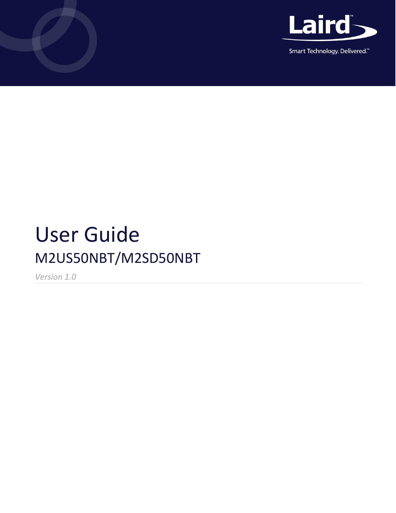
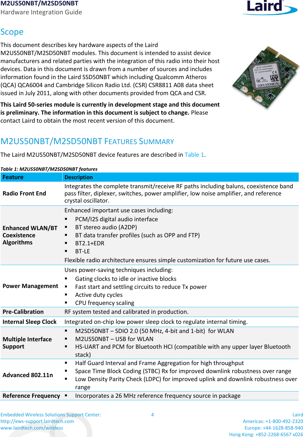
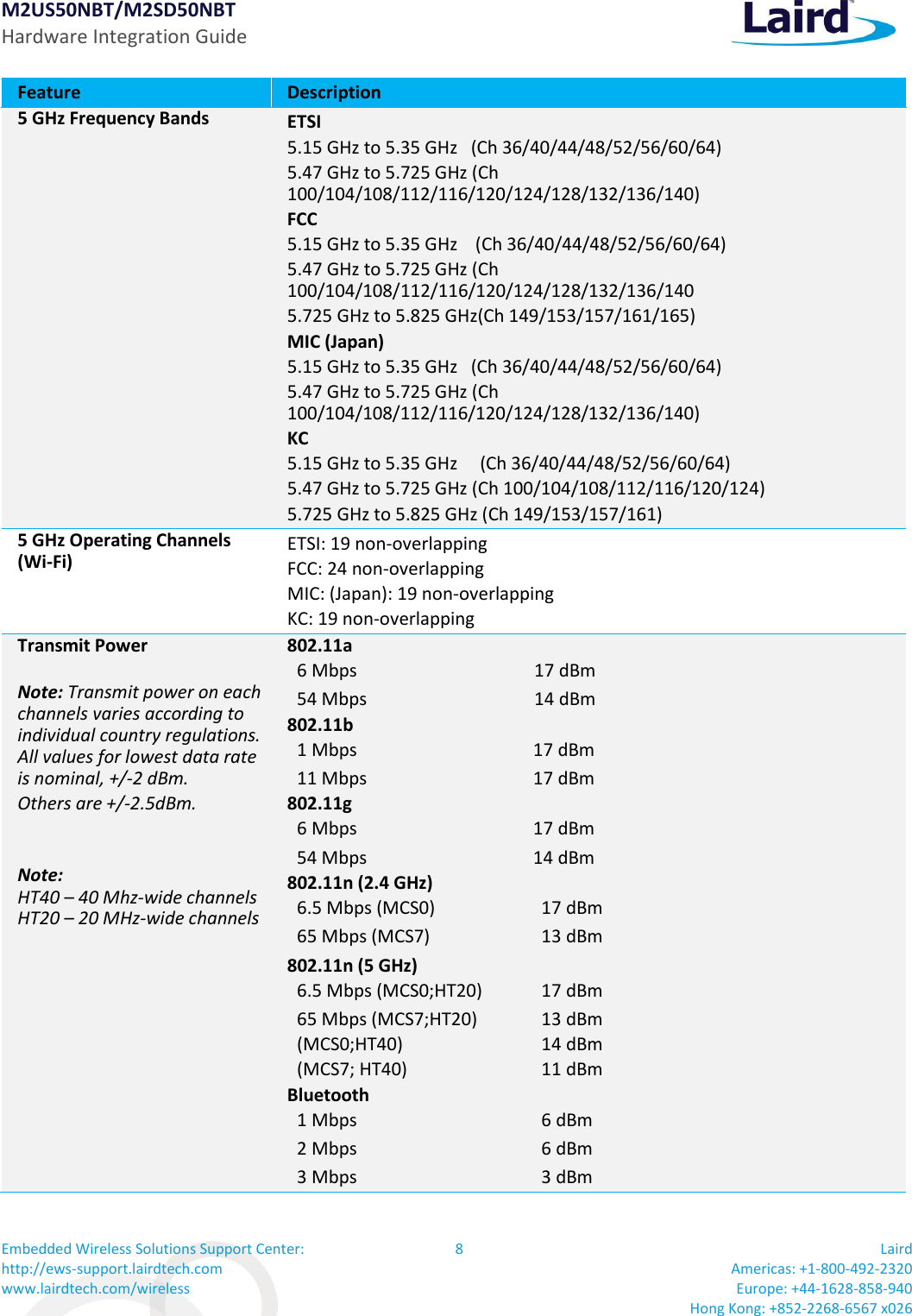
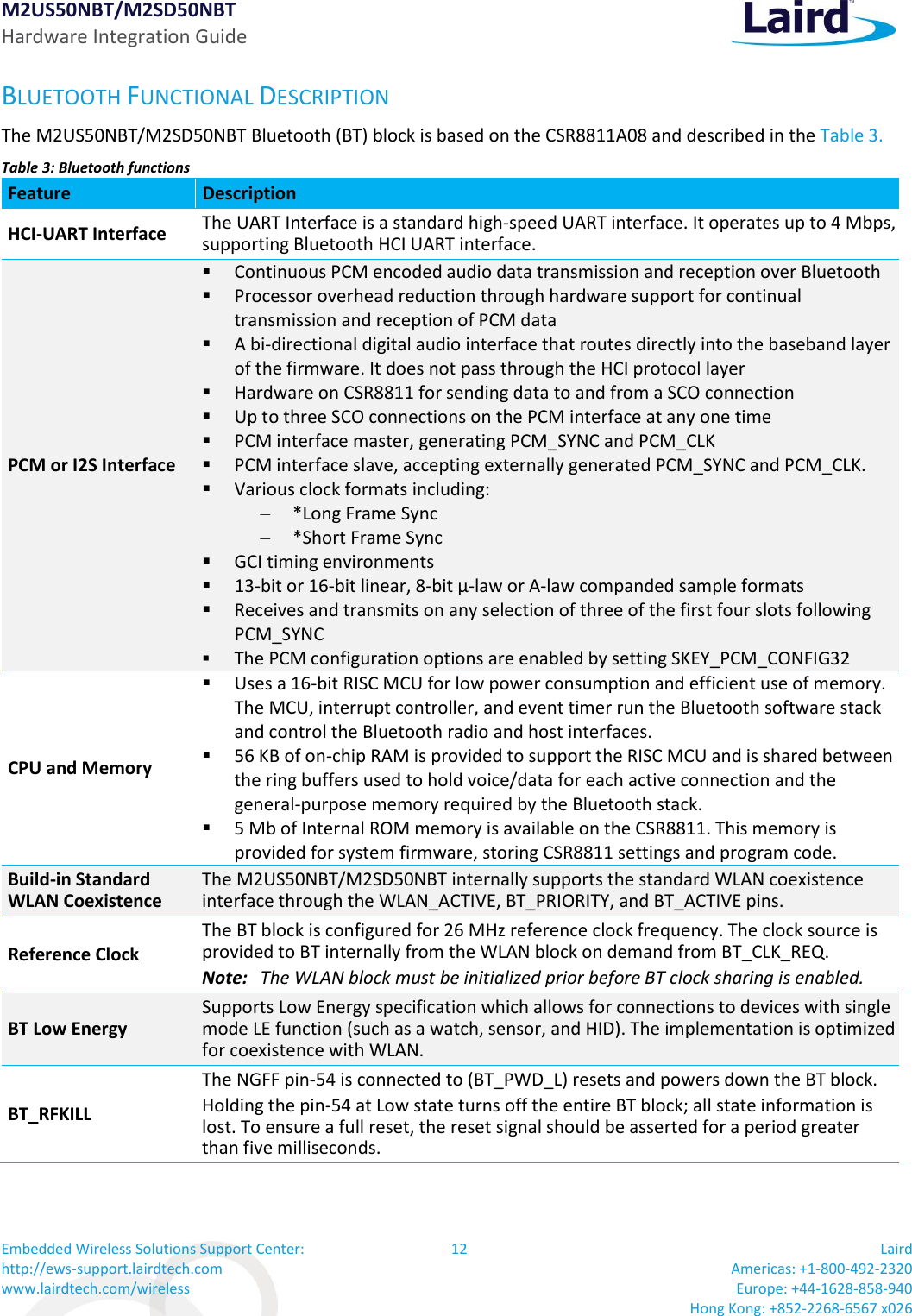
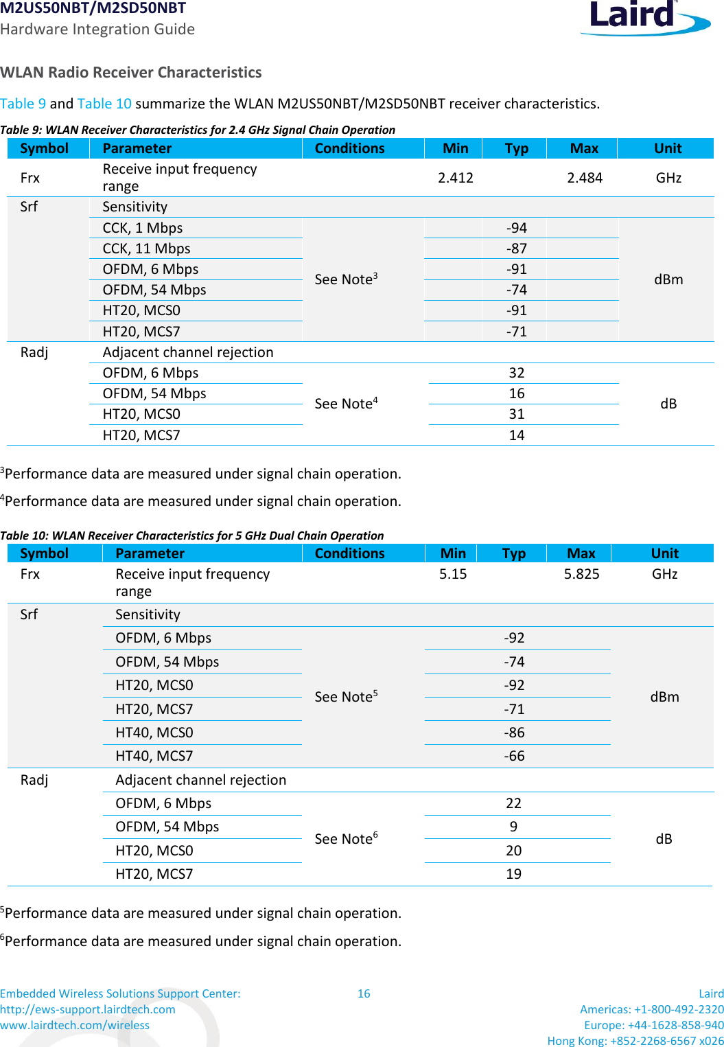
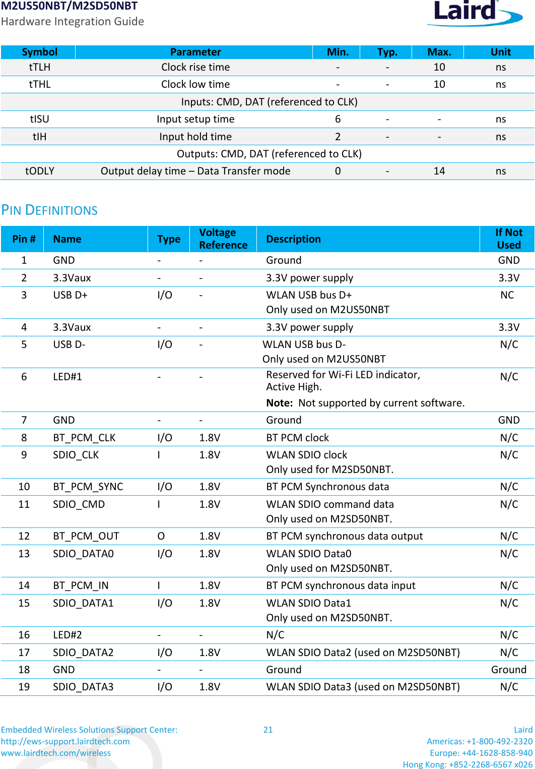
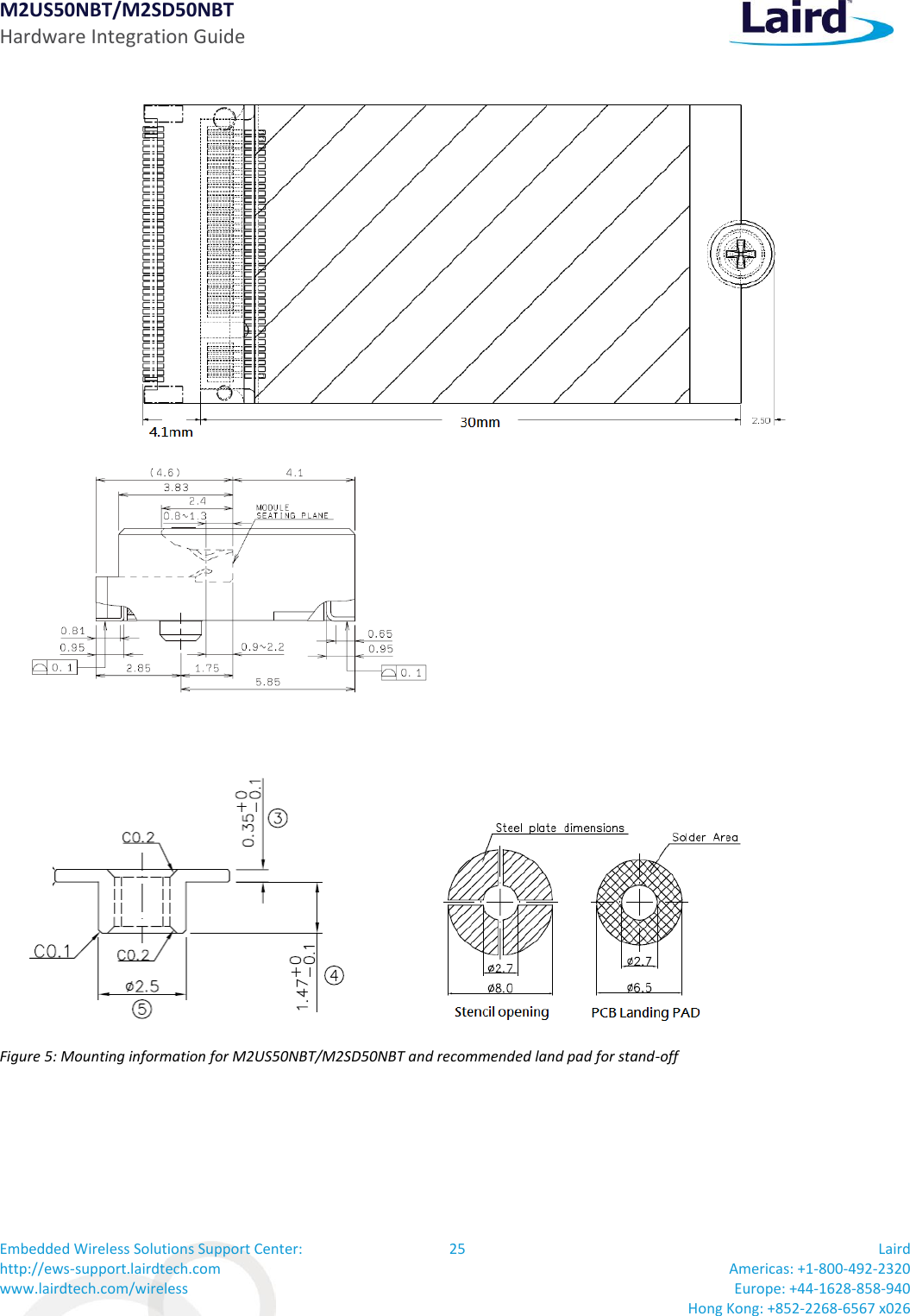
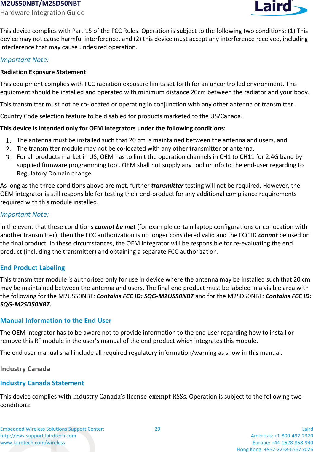
![M2US50NBT/M2SD50NBT Hardware Integration Guide Embedded Wireless Solutions Support Center: http://ews-support.lairdtech.com www.lairdtech.com/wireless 18 Laird Americas: +1-800-492-2320 Europe: +44-1628-858-940 Hong Kong: +852-2268-6567 x026 Freq. Mode/Rate [Mbps] Output Power Per Chain [dBm] Typical Current Consumption Single Chain (mA)8 Max. Current Consumption Single Chain (mA)8 5180MHz 54 Mbps 15dBm 490 590 HT20 MCS7 14dBm 450 560 HT40 MCS7 12dBm 470 540 5500MHz 54 Mbps 15dBm 490 590 HT20 MCS7 14dBm 450 560 HT40 MCS7 12dBm 470 540 5825MHz 54 Mbps 15dBm 490 590 HT20 MCS7 14dBm 450 560 HT40 MCS7 12dBm 470 540 7Performance data are measured under single chain operation. Note: Final TX power values on each channel are limited by the regulatory certification test limit. Note: 2.4 GHz does not support HT40 operation, only 5 GHz support HT40 operation. BLUETOOTH RADIO CHARACTERISTICS Table 13 through Table 14 describe the basic rate transmitter performance, enhanced data transmitter performance, basic rate receiver performance, enhanced rate receiver performance, and current consumption conditions at 25°C. Table 13: Basic Rate Transmitter Performance Temperature at 25°C (3.3V) Test Parameter Min Typ Max BT Spec. Unit Maximum RF Output Power 2 6 — –6 to +10 dBm Frequency Range 2.4 — 2.4835 2.4 ≤ f ≤ 2.4835 GHz 20 dB Bandwidth — 925 — ≤ 1000 KHz Adjacent Channel TX Power F = F0 + 2 MHz — –36 — ≤ –20 dBm Adjacent Channel TX Power F = F0 +3 MHz — –42 — ≤ –40 dBm Δf1avg Maximum Modulation 140 165 175 140 < Δf1avg < 175 KHz Δf2max Minimum Modulation — 135 — ≥ 115 KHz Δf2avg/Δf1avg — 0.9 — ≥ 0.80 — Initial Carrier Frequency — 5 — ≤±75 KHz Drift Rate — 5 — ≤ 20 KHz/50 µs Drift (DH1 packet) — 6 — ≤25 KHz Drift (DH5 packet) — 7 — ≤ 40 KHz](https://usermanual.wiki/Laird-Connectivity/M2US50NBT/User-Guide-2909679-Page-18.png)
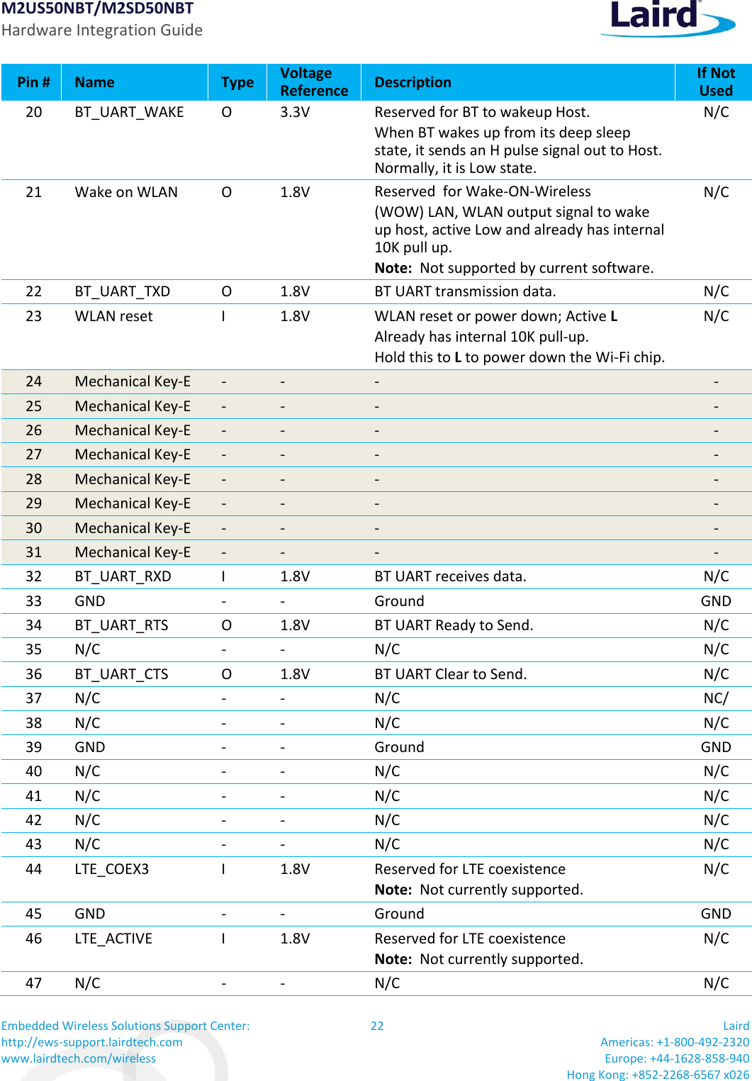
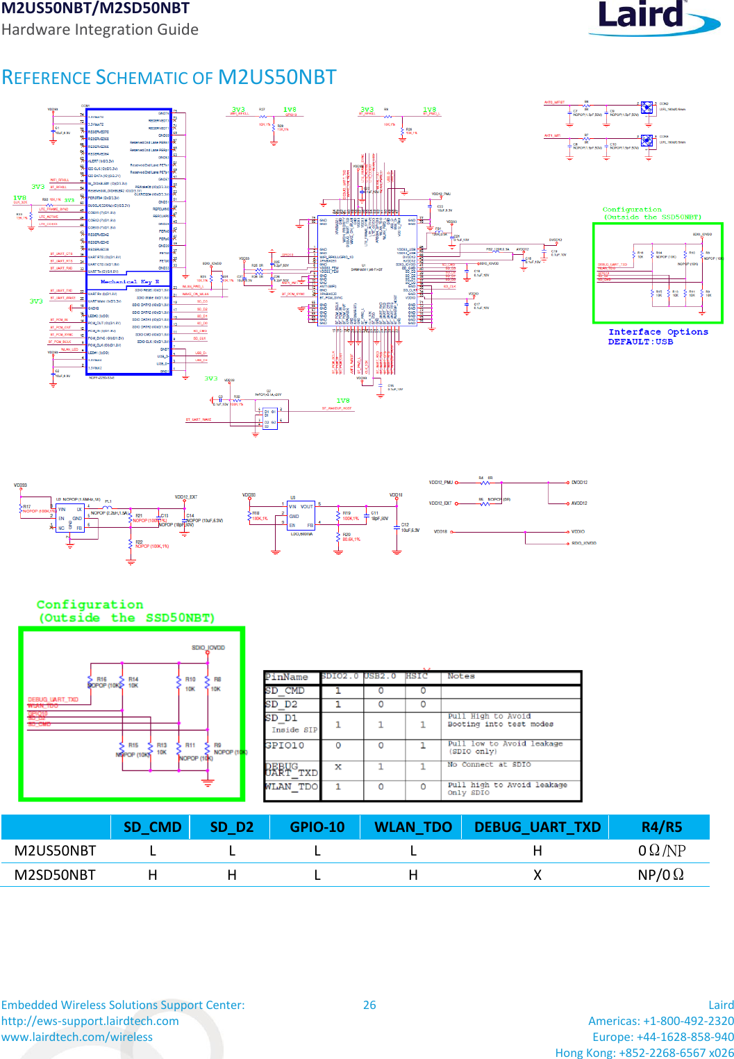
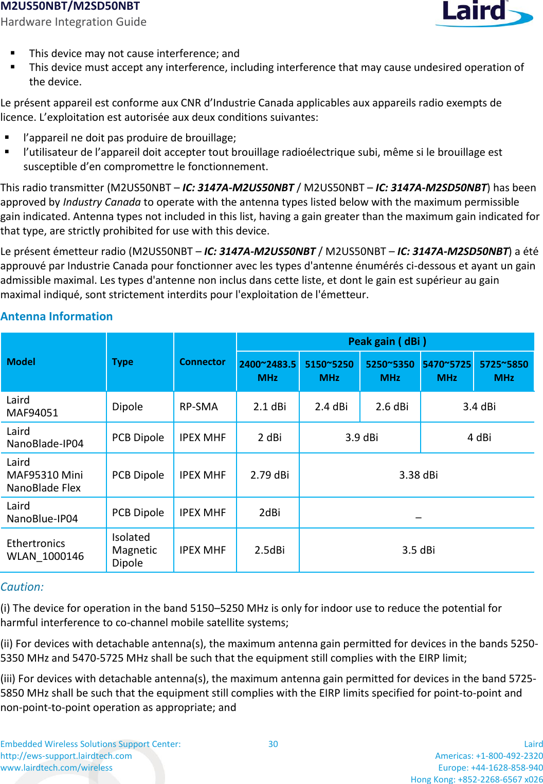
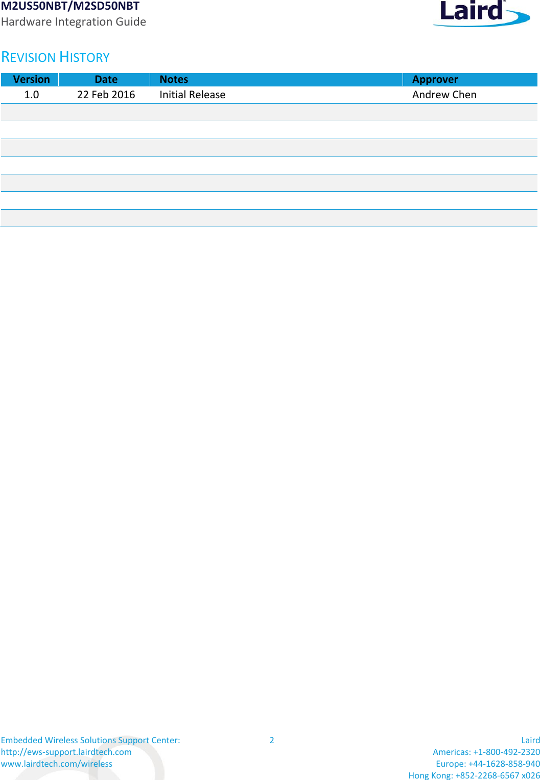
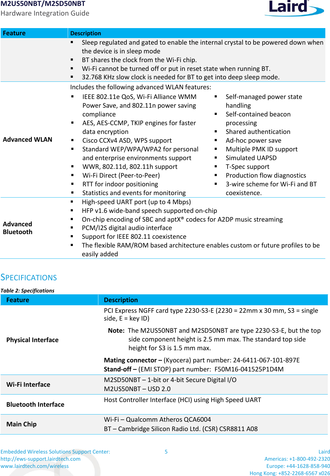
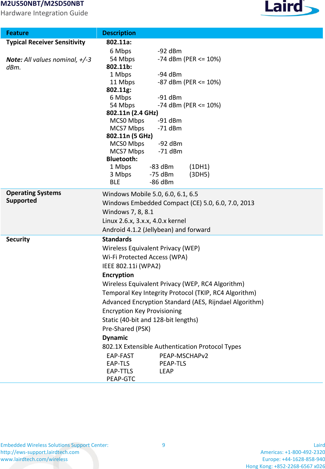
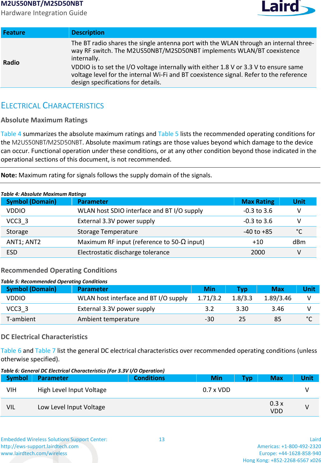
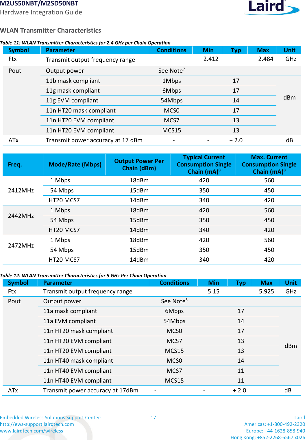
![M2US50NBT/M2SD50NBT Hardware Integration Guide Embedded Wireless Solutions Support Center: http://ews-support.lairdtech.com www.lairdtech.com/wireless 33 Laird Americas: +1-800-492-2320 Europe: +44-1628-858-940 Hong Kong: +852-2268-6567 x026 Reference the Declaration of Conformities listed below for a full list of the standards that the modules were tested to. Test reports are available upon request. EU DECLARATIONS OF CONFORMITY M2US50NBT/M2SD50NBT Manufacturer: Laird Product: M2US50NBT/M2SD50NBT EU Directive: RTTE 1995/5/EC Conformity Assessment: Annex IV Reference standards used for presumption of conformity: Article Number Requirement Reference standard(s) 3.1a Health and Safety EN60950-1:2006+A11:2009+A1:2010+A12:2011 3.1b Protection requirements with respect to electromagnetic compatibility EN 301 489-1 V1.9.2 (2011-09) EN 301 489-17 V2.2.1 (2012-09) Emissions: EN55022:2006/A1:2007 (Class B) Immunity: EN61000-4-2:2009 EN61000-4-3:2006/A1:2008/A2:2010 3.2 Means of the efficient use of the radio frequency spectrum EN 300 328 V1.8.1 (2012-06) EN 301 893 v1.8.1 ORDERING INFORMATION Part Number Description M2US50NBT 2X2 802.11 a/b/g/n with BT4.0 dual mode module. WLAN run at USB bus. BT run at UART/PCM M2SD50NBT 2X2 802.11 a/b/g/n with BT4.0 dual mode module. WLAN run at SDIO bus. BT run at UART/PCM General Comments This is a preliminary datasheet. Please check with Laird for the latest information before commencing a design. If in doubt, ask. Česky [Czech] [Jméno výrobce] tímto prohlašuje, že tento [typ zařízení] je ve shodě se základními požadavky a dalšími příslušnými ustanoveními směrnice 1999/5/ES. Dansk [Danish] Undertegnede [fabrikantens navn] erklærer herved, at følgende udstyr [udstyrets typebetegnelse] overholder de væsentlige krav og øvrige relevante krav i direktiv 1999/5/EF. Deutsch [German] Hiermit erklärt [Name des Herstellers], dass sich das Gerät [Gerätetyp] in Übereinstimmung mit den grundlegenden Anforderungen und den übrigen einschlägigen Bestimmungen der Richtlinie 1999/5/EG befindet.](https://usermanual.wiki/Laird-Connectivity/M2US50NBT/User-Guide-2909679-Page-33.png)
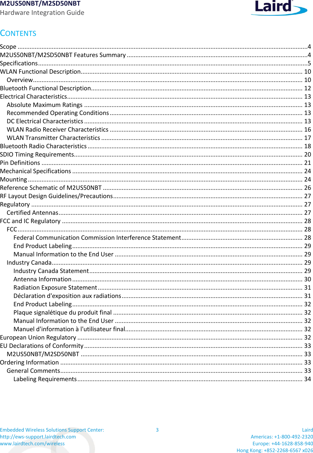
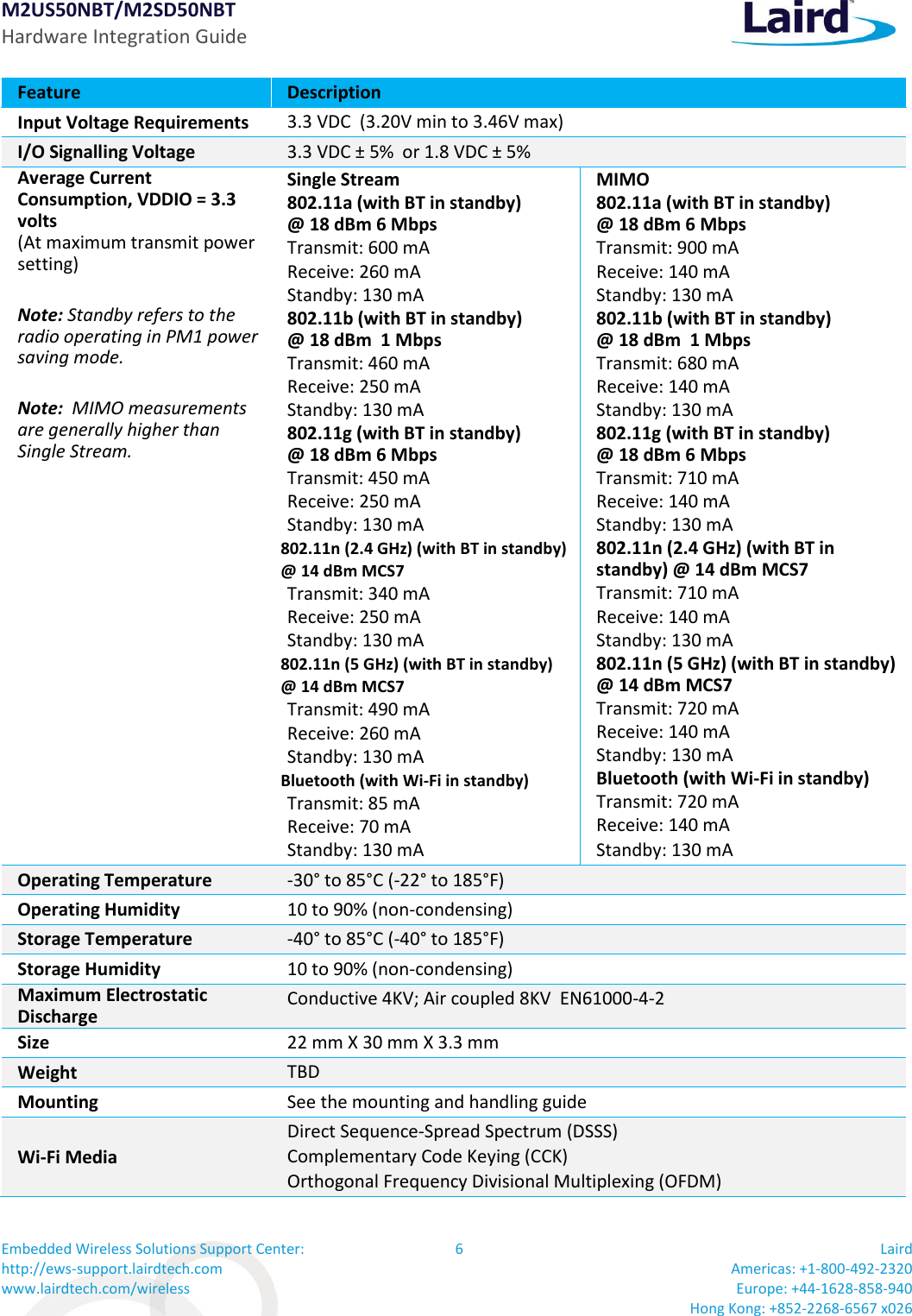
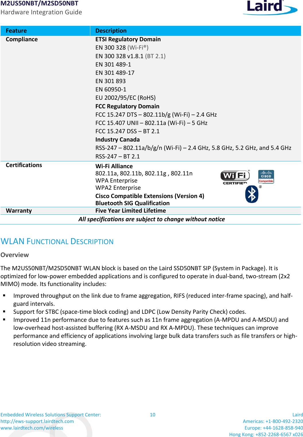
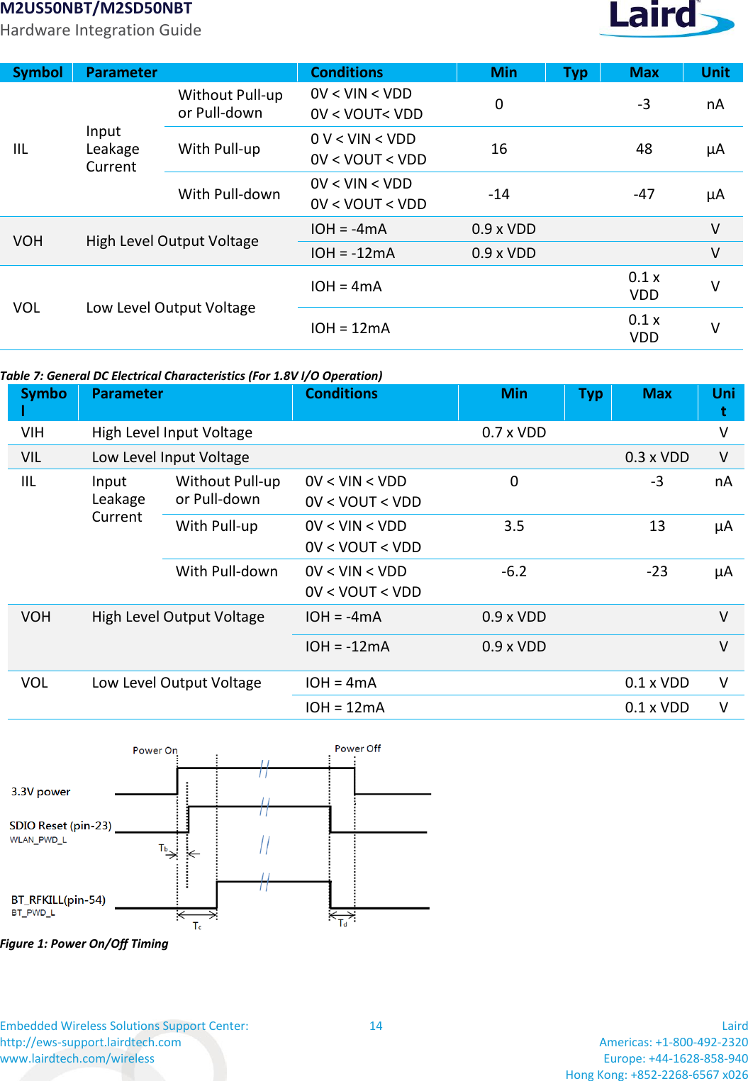
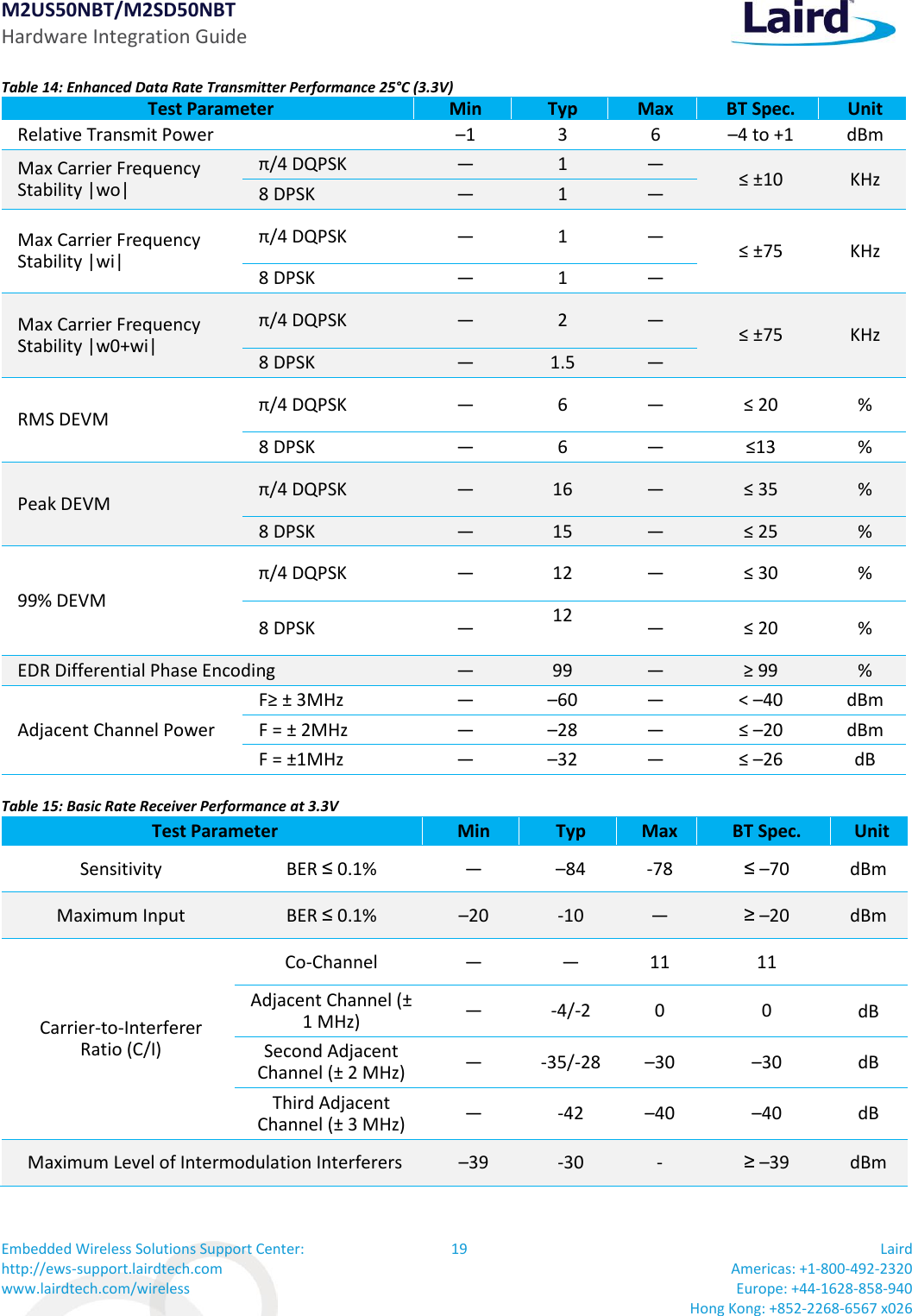
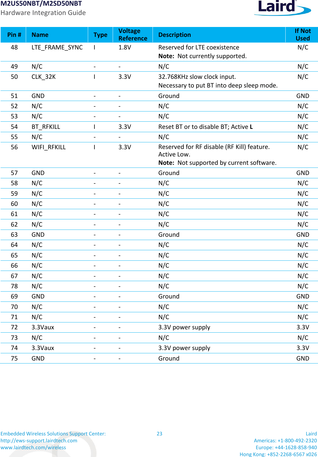
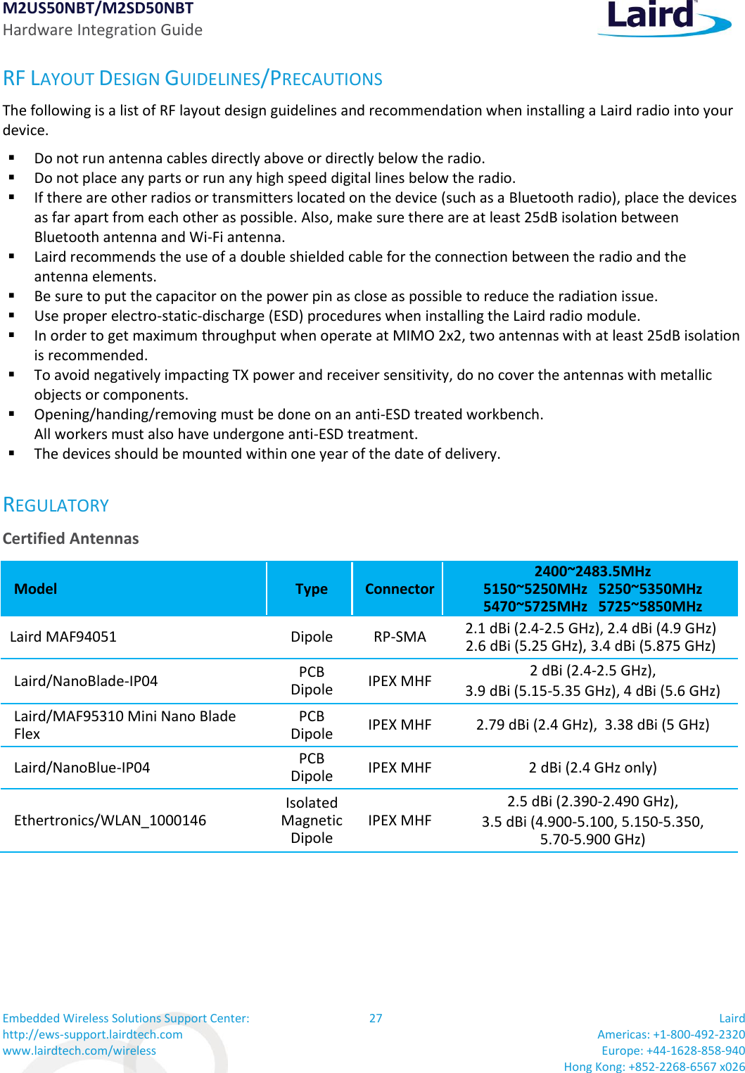
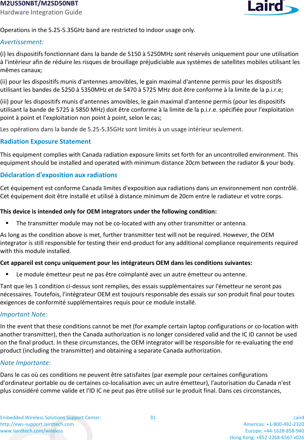
![M2US50NBT/M2SD50NBT Hardware Integration Guide Embedded Wireless Solutions Support Center: http://ews-support.lairdtech.com www.lairdtech.com/wireless 34 Laird Americas: +1-800-492-2320 Europe: +44-1628-858-940 Hong Kong: +852-2268-6567 x026 Eesti [Estonian] Käesolevaga kinnitab [tootja nimi = name of manufacturer] seadme [seadme tüüp = type of equipment] vastavust direktiivi 1999/5/EÜ põhinõuetele ja nimetatud direktiivist tulenevatele teistele asjakohastele sätetele. English Hereby, [name of manufacturer], declares that this [type of equipment] is in compliance with the essential requirements and other relevant provisions of Directive 1999/5/EC. Español [Spanish] Por medio de la presente [nombre del fabricante] declara que el [clase de equipo] cumple con los requisitos esenciales y cualesquiera otras disposiciones aplicables o exigibles de la Directiva 1999/5/CE. Ελληνική [Greek] ΜΕ ΤΗΝ ΠΑΡΟΥΣΑ [name of manufacturer] ΔΗΛΩΝΕΙ ΟΤΙ [type of equipment] ΣΥΜΜΟΡΦΩΝΕΤΑΙ ΠΡΟΣ ΤΙΣ ΟΥΣΙΩΔΕΙΣ ΑΠΑΙΤΗΣΕΙΣ ΚΑΙ ΤΙΣ ΛΟΙΠΕΣ ΣΧΕΤΙΚΕΣ ΔΙΑΤΑΞΕΙΣ ΤΗΣ ΟΔΗΓΙΑΣ 1999/5/ΕΚ. Français [French] Par la présente [nom du fabricant] déclare que l'appareil [type d'appareil] est conforme aux exigences essentielles et aux autres dispositions pertinentes de la directive 1999/5/CE. Italiano [Italian] Con la presente [nome del costruttore] dichiara che questo [tipo di apparecchio] è conforme ai requisiti essenziali ed alle altre disposizioni pertinenti stabilite dalla direttiva 1999/5/CE. Latviski [Latvian] Aršo[name of manufacturer /izgatavotājanosaukums] deklarē, ka[type of equipment / iekārtas tips]atbilstDirektīvas 1999/5/EK būtiskajāmprasībām un citiemar to saistītajiemnoteikumiem. Lietuvių [Lithuanian] Šiuo [manufacturer name] deklaruoja, kad šis [equipment type] atitinka esminius reikalavimus ir kitas 1999/5/EB Direktyvos nuostatas. Nederlands [Dutch] Hierbij verklaart [naam van de fabrikant] dat het toestel [type van toestel] in overeenstemming is met de essentiële eisen en de andere relevante bepalingen van richtlijn 1999/5/EG. Malti [Maltese] Hawnhekk, [isem tal-manifattur], jiddikjara li dan [il-mudel tal-prodott] jikkonforma mal-ħtiġijiet essenzjali u ma provvedimenti oħrajn relevanti li hemm fid-Dirrettiva 1999/5/EC. Magyar [Hungarian] Alulírott, [gyártó neve] nyilatkozom, hogy a [... típus]megfelel a vonatkozó alapvetõ követelményeknek és az 1999/5/EC irányelv egyéb elõírásainak. Polski [Polish] Niniejszym [nazwa producenta] oświadcza, że [nazwa wyrobu] jest zgodny z zasadniczymi wymogami oraz pozostałymi stosownymi postanowieniami Dyrektywy 1999/5/EC. Português [Portuguese] [Nome do fabricante] declara que este [tipo de equipamento] está conforme com os requisitos essenciais e outras disposições da Directiva 1999/5/CE. Slovensko [Slovenian] [Ime proizvajalca] izjavlja, da je ta [tip opreme] v skladu z bistvenimi zahtevami in ostalimi relevantnimi določili direktive 1999/5/ES. Slovensky [Slovak] [Menovýrobcu]týmtovyhlasuje, že[typzariadenia]spĺňazákladnépožiadavky a všetkypríslušnéustanoveniaSmernice 1999/5/ES. Suomi [Finnish] [Valmistaja = manufacturer] vakuuttaa täten että [type of equipment = laitteen tyyppimerkintä] tyyppinen laite on direktiivin 1999/5/EY oleellisten vaatimusten ja sitä koskevien direktiivin muiden ehtojen mukainen. Svenska [Swedish] Härmed intygar [företag] att denna [utrustningstyp] står I överensstämmelse med de väsentliga egenskapskrav och övriga relevanta bestämmelser som framgår av direktiv 1999/5/EG. Labeling Requirements The final end product must be labeled in a visible area with the following notice:](https://usermanual.wiki/Laird-Connectivity/M2US50NBT/User-Guide-2909679-Page-34.png)