Laird Connectivity M2US50NBT 802.11abgn M.2 module w/USB interface User Manual
Laird Technologies 802.11abgn M.2 module w/USB interface Users Manual
Users Manual

A
User Guide
M2US50NBT/M2SD50NBT
Version 1.0

M2US50NBT/M2SD50NBT
Hardware Integration Guide
Embedded Wireless Solutions Support Center:
http://ews-support.lairdtech.com
www.lairdtech.com/wireless
2
Laird
Americas: +1-800-492-2320
Europe: +44-1628-858-940
Hong Kong: +852-2268-6567 x026
REVISION HISTORY
Version
Date
Notes
Approver
1.0
22 Feb 2016
Initial Release
Andrew Chen

M2US50NBT/M2SD50NBT
Hardware Integration Guide
Embedded Wireless Solutions Support Center:
http://ews-support.lairdtech.com
www.lairdtech.com/wireless
3
Laird
Americas: +1-800-492-2320
Europe: +44-1628-858-940
Hong Kong: +852-2268-6567 x026
CONTENTS
Scope ..........................................................................................................................................................................4
M2US50NBT/M2SD50NBT Features Summary ..........................................................................................................4
Specifications ..............................................................................................................................................................5
WLAN Functional Description.................................................................................................................................. 10
Overview .............................................................................................................................................................. 10
Bluetooth Functional Description ............................................................................................................................ 12
Electrical Characteristics .......................................................................................................................................... 13
Absolute Maximum Ratings ................................................................................................................................ 13
Recommended Operating Conditions ................................................................................................................. 13
DC Electrical Characteristics ................................................................................................................................ 13
WLAN Radio Receiver Characteristics ................................................................................................................. 16
WLAN Transmitter Characteristics ...................................................................................................................... 17
Bluetooth Radio Characteristics .............................................................................................................................. 18
SDIO Timing Requirements...................................................................................................................................... 20
Pin Definitions ......................................................................................................................................................... 21
Mechanical Specifications ....................................................................................................................................... 24
Mounting ................................................................................................................................................................. 24
Reference Schematic of M2US50NBT ..................................................................................................................... 26
RF Layout Design Guidelines/Precautions ............................................................................................................... 27
Regulatory ............................................................................................................................................................... 27
Certified Antennas ............................................................................................................................................... 27
FCC and IC Regulatory ............................................................................................................................................. 28
FCC ....................................................................................................................................................................... 28
Federal Communication Commission Interference Statement ....................................................................... 28
End Product Labeling ....................................................................................................................................... 29
Manual Information to the End User .............................................................................................................. 29
Industry Canada ................................................................................................................................................... 29
Industry Canada Statement ............................................................................................................................. 29
Antenna Information ....................................................................................................................................... 30
Radiation Exposure Statement ........................................................................................................................ 31
Déclaration d'exposition aux radiations .......................................................................................................... 31
End Product Labeling ....................................................................................................................................... 32
Plaque signalétique du produit final ............................................................................................................... 32
Manual Information to the End User .............................................................................................................. 32
Manuel d'information à l'utilisateur final ........................................................................................................ 32
European Union Regulatory .................................................................................................................................... 32
EU Declarations of Conformity ................................................................................................................................ 33
M2US50NBT/M2SD50NBT .................................................................................................................................. 33
Ordering Information .............................................................................................................................................. 33
General Comments .............................................................................................................................................. 33
Labeling Requirements .................................................................................................................................... 34
M2US50NBT/M2SD50NBT
Hardware Integration Guide
Embedded Wireless Solutions Support Center:
http://ews-support.lairdtech.com
www.lairdtech.com/wireless
4
Laird
Americas: +1-800-492-2320
Europe: +44-1628-858-940
Hong Kong: +852-2268-6567 x026
Scope
This document describes key hardware aspects of the Laird
M2US50NBT/M2SD50NBT modules. This document is intended to assist device
manufacturers and related parties with the integration of this radio into their host
devices. Data in this document is drawn from a number of sources and includes
information found in the Laird SSD50NBT which including Qualcomm Atheros
(QCA) QCA6004 and Cambridge Silicon Radio Ltd. (CSR) CSR8811 A08 data sheet
issued in July 2011, along with other documents provided from QCA and CSR.
This Laird 50-series module is currently in development stage and this document
is preliminary. The information in this document is subject to change. Please
contact Laird to obtain the most recent version of this document.
M2US50NBT/M2SD50NBT FEATURES SUMMARY
The Laird M2US50NBT/M2SD50NBT device features are described in Table 1.
Table 1: M2US50NBT/M2SD50NBT features
Feature
Description
Radio Front End
Integrates the complete transmit/receive RF paths including baluns, coexistence band
pass filter, diplexer, switches, power amplifier, low noise amplifier, and reference
crystal oscillator.
Enhanced WLAN/BT
Coexistence
Algorithms
Enhanced important use cases including:
PCM/I2S digital audio interface
BT stereo audio (A2DP)
BT data transfer profiles (such as OPP and FTP)
BT2.1+EDR
BT-LE
Flexible radio architecture ensures simple customization for future use cases.
Power Management
Uses power-saving techniques including:
Gating clocks to idle or inactive blocks
Fast start and settling circuits to reduce Tx power
Active duty cycles
CPU frequency scaling
Pre-Calibration
RF system tested and calibrated in production.
Internal Sleep Clock
Integrated on-chip low power sleep clock to regulate internal timing.
Multiple Interface
Support
M2SD50NBT – SDIO 2.0 (50 MHz, 4-bit and 1-bit) for WLAN
M2US50NBT – USB for WLAN
HS-UART and PCM for Bluetooth HCI (compatible with any upper layer Bluetooth
stack)
Advanced 802.11n
Half Guard Interval and Frame Aggregation for high throughput
Space Time Block Coding (STBC) Rx for improved downlink robustness over range
Low Density Parity Check (LDPC) for improved uplink and downlink robustness over
range
Reference Frequency
Incorporates a 26 MHz reference frequency source in package
M2US50NBT/M2SD50NBT
Hardware Integration Guide
Embedded Wireless Solutions Support Center:
http://ews-support.lairdtech.com
www.lairdtech.com/wireless
5
Laird
Americas: +1-800-492-2320
Europe: +44-1628-858-940
Hong Kong: +852-2268-6567 x026
Feature
Description
Sleep regulated and gated to enable the internal crystal to be powered down when
the device is in sleep mode
BT shares the clock from the Wi-Fi chip.
Wi-Fi cannot be turned off or put in reset state when running BT.
32.768 KHz slow clock is needed for BT to get into deep sleep mode.
Advanced WLAN
Includes the following advanced WLAN features:
IEEE 802.11e QoS, Wi-Fi Alliance WMM
Power Save, and 802.11n power saving
compliance
AES, AES-CCMP, TKIP engines for faster
data encryption
Cisco CCXv4 ASD, WPS support
Standard WEP/WPA/WPA2 for personal
and enterprise environments support
WWR, 802.11d, 802.11h support
Wi-Fi Direct (Peer-to-Peer)
RTT for indoor positioning
Statistics and events for monitoring
Self-managed power state
handling
Self-contained beacon
processing
Shared authentication
Ad-hoc power save
Multiple PMK ID support
Simulated UAPSD
T-Spec support
Production flow diagnostics
3-wire scheme for Wi-Fi and BT
coexistence.
Advanced
Bluetooth
High-speed UART port (up to 4 Mbps)
HFP v1.6 wide-band speech supported on-chip
On-chip encoding of SBC and aptX® codecs for A2DP music streaming
PCM/I2S digital audio interface
Support for IEEE 802.11 coexistence
The flexible RAM/ROM based architecture enables custom or future profiles to be
easily added
SPECIFICATIONS
Table 2: Specifications
Feature
Description
Physical Interface
PCI Express NGFF card type 2230-S3-E (2230 = 22mm x 30 mm, S3 = single
side, E = key ID)
Note: The M2US50NBT and M2SD50NBT are type 2230-S3-E, but the top
side component height is 2.5 mm max. The standard top side
height for S3 is 1.5 mm max.
Mating connector – (Kyocera) part number: 24-6411-067-101-897E
Stand-off – (EMI STOP) part number: F50M16-041525P1D4M
Wi-Fi Interface
M2SD50NBT – 1-bit or 4-bit Secure Digital I/O
M2US50NBT – USD 2.0
Bluetooth Interface
Host Controller Interface (HCI) using High Speed UART
Main Chip
Wi-Fi – Qualcomm Atheros QCA6004
BT – Cambridge Silicon Radio Ltd. (CSR) CSR8811 A08
M2US50NBT/M2SD50NBT
Hardware Integration Guide
Embedded Wireless Solutions Support Center:
http://ews-support.lairdtech.com
www.lairdtech.com/wireless
6
Laird
Americas: +1-800-492-2320
Europe: +44-1628-858-940
Hong Kong: +852-2268-6567 x026
Feature
Description
Input Voltage Requirements
3.3 VDC (3.20V min to 3.46V max)
I/O Signalling Voltage
3.3 VDC ± 5% or 1.8 VDC ± 5%
Average Current
Consumption, VDDIO = 3.3
volts
(At maximum transmit power
setting)
Note: Standby refers to the
radio operating in PM1 power
saving mode.
Note: MIMO measurements
are generally higher than
Single Stream.
Single Stream
802.11a (with BT in standby)
@ 18 dBm 6 Mbps
Transmit: 600 mA
Receive: 260 mA
Standby: 130 mA
802.11b (with BT in standby)
@ 18 dBm 1 Mbps
Transmit: 460 mA
Receive: 250 mA
Standby: 130 mA
802.11g (with BT in standby)
@ 18 dBm 6 Mbps
Transmit: 450 mA
Receive: 250 mA
Standby: 130 mA
802.11n (2.4 GHz) (with BT in standby)
@ 14 dBm MCS7
Transmit: 340 mA
Receive: 250 mA
Standby: 130 mA
802.11n (5 GHz) (with BT in standby)
@ 14 dBm MCS7
Transmit: 490 mA
Receive: 260 mA
Standby: 130 mA
Bluetooth (with Wi-Fi in standby)
Transmit: 85 mA
Receive: 70 mA
Standby: 130 mA
MIMO
802.11a (with BT in standby)
@ 18 dBm 6 Mbps
Transmit: 900 mA
Receive: 140 mA
Standby: 130 mA
802.11b (with BT in standby)
@ 18 dBm 1 Mbps
Transmit: 680 mA
Receive: 140 mA
Standby: 130 mA
802.11g (with BT in standby)
@ 18 dBm 6 Mbps
Transmit: 710 mA
Receive: 140 mA
Standby: 130 mA
802.11n (2.4 GHz) (with BT in
standby) @ 14 dBm MCS7
Transmit: 710 mA
Receive: 140 mA
Standby: 130 mA
802.11n (5 GHz) (with BT in standby)
@ 14 dBm MCS7
Transmit: 720 mA
Receive: 140 mA
Standby: 130 mA
Bluetooth (with Wi-Fi in standby)
Transmit: 720 mA
Receive: 140 mA
Standby: 130 mA
Operating Temperature
-30° to 85°C (-22° to 185°F)
Operating Humidity
10 to 90% (non-condensing)
Storage Temperature
-40° to 85°C (-40° to 185°F)
Storage Humidity
10 to 90% (non-condensing)
Maximum Electrostatic
Discharge
Conductive 4KV; Air coupled 8KV EN61000-4-2
Size
22 mm X 30 mm X 3.3 mm
Weight
TBD
Mounting
See the mounting and handling guide
Wi-Fi Media
Direct Sequence-Spread Spectrum (DSSS)
Complementary Code Keying (CCK)
Orthogonal Frequency Divisional Multiplexing (OFDM)

M2US50NBT/M2SD50NBT
Hardware Integration Guide
Embedded Wireless Solutions Support Center:
http://ews-support.lairdtech.com
www.lairdtech.com/wireless
7
Laird
Americas: +1-800-492-2320
Europe: +44-1628-858-940
Hong Kong: +852-2268-6567 x026
Feature
Description
Bluetooth Media
Frequency Hopping Spread Spectrum (FHSS)
Wi-Fi Media Access Protocol
Carrier sense multiple access with collision avoidance (CSMA/CA)
Network Architecture Types
Infrastructure and ad-hoc
Wi-Fi Standards
IEEE 802.11a, 802.11b, 802.11d, 802.11e, 802.11g, 802.11h, 802.11i,
802.11n, 802.11r
Bluetooth Standards
Bluetooth version 2.1 with Enhanced Data Rate
Bluetooth 4.0 (Bluetooth Low Energy or BLE)
Wi-Fi Data Rates Supported
11a (OFDM) 6, 9, 12, 18, 24, 36, 48, 54 Mbps
802.11b (DSSS, CCK) 1, 2, 5.5, 11 Mbps
802.11g (OFDM) 6, 9, 12, 18, 24, 36, 48, 54 Mbps
802.11n (OFDM, MCS 0-15)
Full Guard Interval: 6.5,13.0, 19.5, 26.0,39.0,52.0,58.5,65.0, 13.0,26.0,39.0,
52.0, 78.0,104.0,117.0 Mbps
Short Guard Interval: 1.2,14.4,21.7,29.9,43.3,57.8,65.0,72.2,
14.4,28.9,43.3,57.8, 86.7,115.6,130.0,144.4 Mbps
Modulation
BPSK @ 1, 6,9, 6.5, 7.2,13 and 14.4 Mbps
QPSK @ 2, 12, 18, 13, 14.4,19.5, 21.7, 26, 28.9, 39,43.3 Mbps
CCK @ 5.5 and 11 Mbps
16-QAM @ 24, 36,26, 29.9,39,43.3,52,57.8,78,86.7 Mbps
64-QAM @ 48,54,52, 57.8, 58.5, 65,72.2,104.0,115.6,117.0,130.0,144.4
Mbps
802.11n Spatial Streams
2 (2x2 MIMO)
Bluetooth Data Rates
Supported
1, 2, 3 Mbps
Bluetooth Modulation
GFSK@ 1 Mbps
Pi/4-DQPSK@ 2 Mbps
8-DPSK@ 3 Mbps
Regulatory Domain Support
FCC (Americas, Parts of Asia, and Middle East)
ETSI (Europe, Middle East, Africa, and Parts of Asia)
IC (Industry Canada )
MIC (Japan) (formerly TELEC) – Option
KC (Korea) (formerly KCC) – Option
2.4 GHz Frequency Bands
ETSI: 2.4 GHz to 2.483 GHz
FCC: 2.4 GHz to 2.473 GHz
MIC: 2.4 GHz to 2.495 GHz
KC: 2.4 GHz to 2.483 GHz
2.4 GHz Operating Channels
(Wi-Fi)
ETSI: 13 (3 non-overlapping)
FCC: 11 (3 non-overlapping)
MIC: 14 (4 non-overlapping)
KC: 13 (3 non-overlapping)
M2US50NBT/M2SD50NBT
Hardware Integration Guide
Embedded Wireless Solutions Support Center:
http://ews-support.lairdtech.com
www.lairdtech.com/wireless
8
Laird
Americas: +1-800-492-2320
Europe: +44-1628-858-940
Hong Kong: +852-2268-6567 x026
Feature
Description
5 GHz Frequency Bands
ETSI
5.15 GHz to 5.35 GHz (Ch 36/40/44/48/52/56/60/64)
5.47 GHz to 5.725 GHz (Ch
100/104/108/112/116/120/124/128/132/136/140)
FCC
5.15 GHz to 5.35 GHz (Ch 36/40/44/48/52/56/60/64)
5.47 GHz to 5.725 GHz (Ch
100/104/108/112/116/120/124/128/132/136/140
5.725 GHz to 5.825 GHz(Ch 149/153/157/161/165)
MIC (Japan)
5.15 GHz to 5.35 GHz (Ch 36/40/44/48/52/56/60/64)
5.47 GHz to 5.725 GHz (Ch
100/104/108/112/116/120/124/128/132/136/140)
KC
5.15 GHz to 5.35 GHz (Ch 36/40/44/48/52/56/60/64)
5.47 GHz to 5.725 GHz (Ch 100/104/108/112/116/120/124)
5.725 GHz to 5.825 GHz (Ch 149/153/157/161)
5 GHz Operating Channels
(Wi-Fi)
ETSI: 19 non-overlapping
FCC: 24 non-overlapping
MIC: (Japan): 19 non-overlapping
KC: 19 non-overlapping
Transmit Power
Note: Transmit power on each
channels varies according to
individual country regulations.
All values for lowest data rate
is nominal, +/-2 dBm.
Others are +/-2.5dBm.
Note:
HT40 – 40 Mhz-wide channels
HT20 – 20 MHz-wide channels
802.11a
6 Mbps
17 dBm
54 Mbps
14 dBm
802.11b
1 Mbps
17 dBm
11 Mbps
17 dBm
802.11g
6 Mbps
17 dBm
54 Mbps
14 dBm
802.11n (2.4 GHz)
6.5 Mbps (MCS0)
17 dBm
65 Mbps (MCS7)
13 dBm
802.11n (5 GHz)
6.5 Mbps (MCS0;HT20)
17 dBm
65 Mbps (MCS7;HT20)
(MCS0;HT40)
(MCS7; HT40)
13 dBm
14 dBm
11 dBm
Bluetooth
1 Mbps
6 dBm
2 Mbps
6 dBm
3 Mbps
3 dBm
M2US50NBT/M2SD50NBT
Hardware Integration Guide
Embedded Wireless Solutions Support Center:
http://ews-support.lairdtech.com
www.lairdtech.com/wireless
9
Laird
Americas: +1-800-492-2320
Europe: +44-1628-858-940
Hong Kong: +852-2268-6567 x026
Feature
Description
Typical Receiver Sensitivity
Note: All values nominal, +/-3
dBm.
802.11a:
6 Mbps
-92 dBm
54 Mbps
-74 dBm (PER <= 10%)
802.11b:
1 Mbps
-94 dBm
11 Mbps
-87 dBm (PER <= 10%)
802.11g:
6 Mbps
-91 dBm
54 Mbps
-74 dBm (PER <= 10%)
802.11n (2.4 GHz)
MCS0 Mbps
-91 dBm
MCS7 Mbps
-71 dBm
802.11n (5 GHz)
MCS0 Mbps
MCS7 Mbps
-92 dBm
-71 dBm
Bluetooth:
1 Mbps
-83 dBm
(1DH1)
3 Mbps
-75 dBm
(3DH5)
BLE
-86 dBm
Operating Systems
Supported
Windows Mobile 5.0, 6.0, 6.1, 6.5
Windows Embedded Compact (CE) 5.0, 6.0, 7.0, 2013
Windows 7, 8, 8.1
Linux 2.6.x, 3.x.x, 4.0.x kernel
Android 4.1.2 (Jellybean) and forward
Security
Standards
Wireless Equivalent Privacy (WEP)
Wi-Fi Protected Access (WPA)
IEEE 802.11i (WPA2)
Encryption
Wireless Equivalent Privacy (WEP, RC4 Algorithm)
Temporal Key Integrity Protocol (TKIP, RC4 Algorithm)
Advanced Encryption Standard (AES, Rijndael Algorithm)
Encryption Key Provisioning
Static (40-bit and 128-bit lengths)
Pre-Shared (PSK)
Dynamic
802.1X Extensible Authentication Protocol Types
EAP-FAST
EAP-TLS
EAP-TTLS
PEAP-GTC
PEAP-MSCHAPv2
PEAP-TLS
LEAP
M2US50NBT/M2SD50NBT
Hardware Integration Guide
Embedded Wireless Solutions Support Center:
http://ews-support.lairdtech.com
www.lairdtech.com/wireless
10
Laird
Americas: +1-800-492-2320
Europe: +44-1628-858-940
Hong Kong: +852-2268-6567 x026
Feature
Description
Compliance
ETSI Regulatory Domain
EN 300 328 (Wi-Fi®)
EN 300 328 v1.8.1 (BT 2.1)
EN 301 489-1
EN 301 489-17
EN 301 893
EN 60950-1
EU 2002/95/EC (RoHS)
FCC Regulatory Domain
FCC 15.247 DTS – 802.11b/g (Wi-Fi) – 2.4 GHz
FCC 15.407 UNII – 802.11a (Wi-Fi) – 5 GHz
FCC 15.247 DSS – BT 2.1
Industry Canada
RSS-247 – 802.11a/b/g/n (Wi-Fi) – 2.4 GHz, 5.8 GHz, 5.2 GHz, and 5.4 GHz
RSS-247 – BT 2.1
Certifications
Wi-Fi Alliance
802.11a, 802.11b, 802.11g , 802.11n
WPA Enterprise
WPA2 Enterprise
Cisco Compatible Extensions (Version 4)
Bluetooth SIG Qualification
Warranty
Five Year Limited Lifetime
All specifications are subject to change without notice
WLAN FUNCTIONAL DESCRIPTION
Overview
The M2US50NBT/M2SD50NBT WLAN block is based on the Laird SSD50NBT SIP (System in Package). It is
optimized for low-power embedded applications and is configured to operate in dual-band, two-stream (2x2
MIMO) mode. Its functionality includes:
Improved throughput on the link due to frame aggregation, RIFS (reduced inter-frame spacing), and half-
guard intervals.
Support for STBC (space-time block coding) and LDPC (Low Density Parity Check) codes.
Improved 11n performance due to features such as 11n frame aggregation (A-MPDU and A-MSDU) and
low-overhead host-assisted buffering (RX A-MSDU and RX A-MPDU). These techniques can improve
performance and efficiency of applications involving large bulk data transfers such as file transfers or high-
resolution video streaming.
M2US50NBT/M2SD50NBT
Hardware Integration Guide
Embedded Wireless Solutions Support Center:
http://ews-support.lairdtech.com
www.lairdtech.com/wireless
11
Laird
Americas: +1-800-492-2320
Europe: +44-1628-858-940
Hong Kong: +852-2268-6567 x026
Other functionality includes the following:
Feature
Description
System Clocking
(RTC Block)
An RTC block controls the clocks and power going to other internal modules. Its inputs
contain sleep requests from these modules and its outputs contain clock enable and
power signals which are used to gate the clocks going to these modules. The RTC block
also manages resets going to other modules with the device. The M2US50NBT/
M2SD50NBT’s clocking is grouped into two types: high-speed and low-speed.
High Speed Clocking
The reference 26 MHz clock source drives the PLL and RF synthesizer of Wi-Fi and
Bluetooth. To minimize power consumption, the reference clock source is powered off in
SLEEP, HOST_OFF, and OFF states.
Low Speed Clocking
These modules require an external sleep clock (32.768 KHz) source from host platform
through pin-50 on the NFGG golden finger. It is used to place BT into deep sleep mode. For
Wi-Fi only application, it is needed.
Interface Clock
The host interface clock represents another clock domain for the
M2US50NBT/M2SD50NBT. This clock comes from the SDIO and is independent from the
other internal clocks. It drives the host interface logic as well as certain registers which can
be accessed by the host in HOST_OFF and SLEEP states.
MAC/BB/RF Block
The M2US50NBT/M2SD50NBT Wireless MAC consists of five major blocks:
Host interface unit (HIU) for bridging to the AHB for bulk data accesses and APB for
register accesses
Ten queue control units (QCU) for transferring TX data
Ten DCF control units (DCU) for managing channel access
Protocol control unit (PCU) for interfacing to baseband
DMA receive unit (DRU) for transferring RX data
Baseband Block
The M2US50NBT/M2SD50NBT baseband block (BB) is the physical layer controller for the
802.11b/g/n air interface.
It modulates data packets in the transmit direction
Detects and demodulates data packets in the receive direction.
It has a direct control interface to the radio to enable hardware to adjust analog gains
and modes dynamically.
Clock Sharing
Clock sharing is implemented on the M2US50NBT/M2SD50NBT. The Bluetooth chip
(CSR8811) receives a reference clock from the Wi-Fi chip (QCA6004). When Wi-Fi is in
power off/reset state, Bluetooth is also off.
External 32.768 KHz signal present on pin 50 allows the BT chip to go into deep sleep
mode and consume lowest amount of power
M2US50NBT/M2SD50NBT
Hardware Integration Guide
Embedded Wireless Solutions Support Center:
http://ews-support.lairdtech.com
www.lairdtech.com/wireless
12
Laird
Americas: +1-800-492-2320
Europe: +44-1628-858-940
Hong Kong: +852-2268-6567 x026
BLUETOOTH FUNCTIONAL DESCRIPTION
The M2US50NBT/M2SD50NBT Bluetooth (BT) block is based on the CSR8811A08 and described in the Table 3.
Table 3: Bluetooth functions
Feature
Description
HCI-UART Interface
The UART Interface is a standard high-speed UART interface. It operates up to 4 Mbps,
supporting Bluetooth HCI UART interface.
PCM or I2S Interface
Continuous PCM encoded audio data transmission and reception over Bluetooth
Processor overhead reduction through hardware support for continual
transmission and reception of PCM data
A bi-directional digital audio interface that routes directly into the baseband layer
of the firmware. It does not pass through the HCI protocol layer
Hardware on CSR8811 for sending data to and from a SCO connection
Up to three SCO connections on the PCM interface at any one time
PCM interface master, generating PCM_SYNC and PCM_CLK
PCM interface slave, accepting externally generated PCM_SYNC and PCM_CLK.
Various clock formats including:
– *Long Frame Sync
– *Short Frame Sync
GCI timing environments
13-bit or 16-bit linear, 8-bit μ-law or A-law companded sample formats
Receives and transmits on any selection of three of the first four slots following
PCM_SYNC
The PCM configuration options are enabled by setting SKEY_PCM_CONFIG32
CPU and Memory
Uses a 16-bit RISC MCU for low power consumption and efficient use of memory.
The MCU, interrupt controller, and event timer run the Bluetooth software stack
and control the Bluetooth radio and host interfaces.
56 KB of on-chip RAM is provided to support the RISC MCU and is shared between
the ring buffers used to hold voice/data for each active connection and the
general-purpose memory required by the Bluetooth stack.
5 Mb of Internal ROM memory is available on the CSR8811. This memory is
provided for system firmware, storing CSR8811 settings and program code.
Build-in Standard
WLAN Coexistence
The M2US50NBT/M2SD50NBT internally supports the standard WLAN coexistence
interface through the WLAN_ACTIVE, BT_PRIORITY, and BT_ACTIVE pins.
Reference Clock
The BT block is configured for 26 MHz reference clock frequency. The clock source is
provided to BT internally from the WLAN block on demand from BT_CLK_REQ.
Note: The WLAN block must be initialized prior before BT clock sharing is enabled.
BT Low Energy
Supports Low Energy specification which allows for connections to devices with single
mode LE function (such as a watch, sensor, and HID). The implementation is optimized
for coexistence with WLAN.
BT_RFKILL
The NGFF pin-54 is connected to (BT_PWD_L) resets and powers down the BT block.
Holding the pin-54 at Low state turns off the entire BT block; all state information is
lost. To ensure a full reset, the reset signal should be asserted for a period greater
than five milliseconds.
M2US50NBT/M2SD50NBT
Hardware Integration Guide
Embedded Wireless Solutions Support Center:
http://ews-support.lairdtech.com
www.lairdtech.com/wireless
13
Laird
Americas: +1-800-492-2320
Europe: +44-1628-858-940
Hong Kong: +852-2268-6567 x026
Feature
Description
Radio
The BT radio shares the single antenna port with the WLAN through an internal three-
way RF switch. The M2US50NBT/M2SD50NBT implements WLAN/BT coexistence
internally.
VDDIO is to set the I/O voltage internally with either 1.8 V or 3.3 V to ensure same
voltage level for the internal Wi-Fi and BT coexistence signal. Refer to the reference
design specifications for details.
ELECTRICAL CHARACTERISTICS
Absolute Maximum Ratings
Table 4 summarizes the absolute maximum ratings and Table 5 lists the recommended operating conditions for
the M2US50NBT/M2SD50NBT. Absolute maximum ratings are those values beyond which damage to the device
can occur. Functional operation under these conditions, or at any other condition beyond those indicated in the
operational sections of this document, is not recommended.
Note: Maximum rating for signals follows the supply domain of the signals.
Table 4: Absolute Maximum Ratings
Symbol (Domain)
Parameter
Max Rating
Unit
VDDIO
WLAN host SDIO interface and BT I/O supply
-0.3 to 3.6
V
VCC3_3
External 3.3V power supply
-0.3 to 3.6
V
Storage
Storage Temperature
-40 to +85
°C
ANT1; ANT2
Maximum RF input (reference to 50-Ω input)
+10
dBm
ESD
Electrostatic discharge tolerance
2000
V
Recommended Operating Conditions
Table 5: Recommended Operating Conditions
Symbol (Domain)
Parameter
Min
Typ
Max
Unit
VDDIO
WLAN host interface and BT I/O supply
1.71/3.2
1.8/3.3
1.89/3.46
V
VCC3_3
External 3.3V power supply
3.2
3.30
3.46
V
T-ambient
Ambient temperature
-30
25
85
°C
DC Electrical Characteristics
Table 6 and Table 7 list the general DC electrical characteristics over recommended operating conditions (unless
otherwise specified).
Table 6: General DC Electrical Characteristics (For 3.3V I/O Operation)
Symbol
Parameter
Conditions
Min
Typ
Max
Unit
VIH
High Level Input Voltage
0.7 x VDD
V
VIL
Low Level Input Voltage
0.3 x
VDD
V
M2US50NBT/M2SD50NBT
Hardware Integration Guide
Embedded Wireless Solutions Support Center:
http://ews-support.lairdtech.com
www.lairdtech.com/wireless
14
Laird
Americas: +1-800-492-2320
Europe: +44-1628-858-940
Hong Kong: +852-2268-6567 x026
Symbol
Parameter
Conditions
Min
Typ
Max
Unit
IIL
Input
Leakage
Current
Without Pull-up
or Pull-down
0V < VIN < VDD
0V < VOUT< VDD
0
-3
nA
With Pull-up
0 V < VIN < VDD
0V < VOUT < VDD
16
48
µA
With Pull-down
0V < VIN < VDD
0V < VOUT < VDD
-14
-47
µA
VOH
High Level Output Voltage
IOH = -4mA
0.9 x VDD
V
IOH = -12mA
0.9 x VDD
V
VOL
Low Level Output Voltage
IOH = 4mA
0.1 x
VDD
V
IOH = 12mA
0.1 x
VDD
V
Table 7: General DC Electrical Characteristics (For 1.8V I/O Operation)
Symbo
l
Parameter
Conditions
Min
Typ
Max
Uni
t
VIH
High Level Input Voltage
0.7 x VDD
V
VIL
Low Level Input Voltage
0.3 x VDD
V
IIL
Input
Leakage
Current
Without Pull-up
or Pull-down
0V < VIN < VDD
0V < VOUT < VDD
0
-3
nA
With Pull-up
0V < VIN < VDD
0V < VOUT < VDD
3.5
13
µA
With Pull-down
0V < VIN < VDD
0V < VOUT < VDD
-6.2
-23
µA
VOH
High Level Output Voltage
IOH = -4mA
0.9 x VDD
V
IOH = -12mA
0.9 x VDD
V
VOL
Low Level Output Voltage
IOH = 4mA
0.1 x VDD
V
IOH = 12mA
0.1 x VDD
V
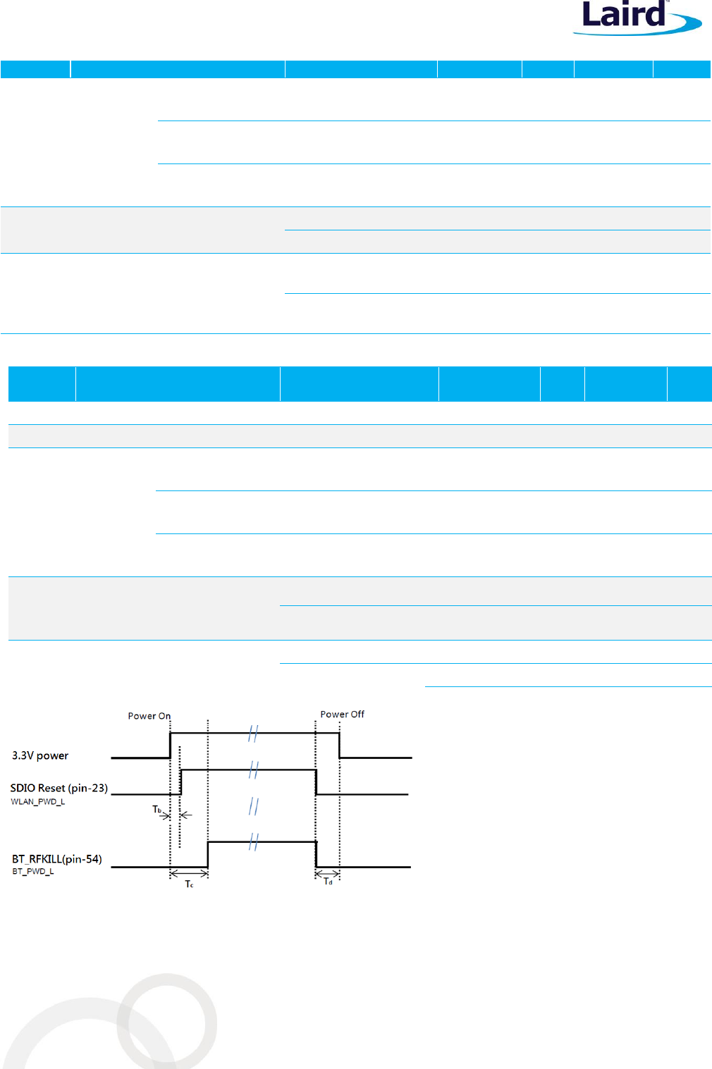
Figure 1: Power On/Off Timing
M2US50NBT/M2SD50NBT
Hardware Integration Guide
Embedded Wireless Solutions Support Center:
http://ews-support.lairdtech.com
www.lairdtech.com/wireless
15
Laird
Americas: +1-800-492-2320
Europe: +44-1628-858-940
Hong Kong: +852-2268-6567 x026
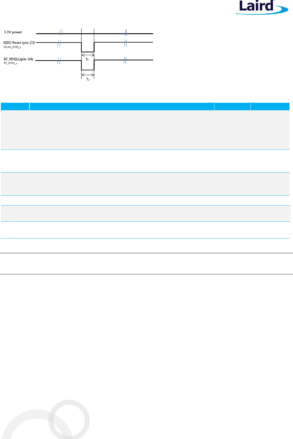
Figure 2: Reset Timing
Table 8: Timing Diagram Definitions
Timing
Description
Min
Unit
Tb
Time between VDD33 (3.3V )supplies valid, to SDIO reset (pin-
56;WLAN_PWD_L ) negation.
Note: have suitable 10K ohm Pull-up on SDIO bus, already. No extra
pull-up resistor is required.
5
µsec
Tc
Time between VDD33 (3.3V) supplies valid and
BT_RFKILL (pin-54; BT_PWD_L ) negation
5
msec
Td
Time between SDIO reset (pin-56;WLAN_PWD_L ) negation and
VDD33 (3.3V) invalid, or time between BT_RFKILL (pin-54;
BT_PWD_L ) negation and VDD33(3.3V) invalid.
0
µsec
Tf
Time of SDIO reset (pin-56;WLAN_PWD_L ) assertion during reset
or power down period. 3.3V should keep ON.
5
µsec
Tg
Time of BT_RFKILL (pin-54; BT_PWD_L )assertion during reset or
power down period. 3.3V should keep ON.
5
msec
Important: There is 10K ohm pull high resistor already implemented on SD_D0, SD_D1, and SD_D3. No
external pull-up is required for those three lines.
M2US50NBT/M2SD50NBT
Hardware Integration Guide
Embedded Wireless Solutions Support Center:
http://ews-support.lairdtech.com
www.lairdtech.com/wireless
16
Laird
Americas: +1-800-492-2320
Europe: +44-1628-858-940
Hong Kong: +852-2268-6567 x026
WLAN Radio Receiver Characteristics
Table 9 and Table 10 summarize the WLAN M2US50NBT/M2SD50NBT receiver characteristics.
Table 9: WLAN Receiver Characteristics for 2.4 GHz Signal Chain Operation
Symbol
Parameter
Conditions
Min
Typ
Max
Unit
Frx
Receive input frequency
range
2.412
2.484
GHz
Srf
Sensitivity
CCK, 1 Mbps
See Note3
-94
dBm
CCK, 11 Mbps
-87
OFDM, 6 Mbps
-91
OFDM, 54 Mbps
-74
HT20, MCS0
-91
HT20, MCS7
-71
Radj
Adjacent channel rejection
OFDM, 6 Mbps
See Note4
32
dB
OFDM, 54 Mbps
16
HT20, MCS0
31
HT20, MCS7
14
3Performance data are measured under signal chain operation.
4Performance data are measured under signal chain operation.
Table 10: WLAN Receiver Characteristics for 5 GHz Dual Chain Operation
Symbol
Parameter
Conditions
Min
Typ
Max
Unit
Frx
Receive input frequency
range
5.15
5.825
GHz
Srf
Sensitivity
OFDM, 6 Mbps
See Note5
-92
dBm
OFDM, 54 Mbps
-74
HT20, MCS0
-92
HT20, MCS7
-71
HT40, MCS0
-86
HT40, MCS7
-66
Radj
Adjacent channel rejection
OFDM, 6 Mbps
See Note6
22
dB
OFDM, 54 Mbps
9
HT20, MCS0
20
HT20, MCS7
19
5Performance data are measured under signal chain operation.
6Performance data are measured under signal chain operation.
M2US50NBT/M2SD50NBT
Hardware Integration Guide
Embedded Wireless Solutions Support Center:
http://ews-support.lairdtech.com
www.lairdtech.com/wireless
17
Laird
Americas: +1-800-492-2320
Europe: +44-1628-858-940
Hong Kong: +852-2268-6567 x026
WLAN Transmitter Characteristics
Table 11: WLAN Transmitter Characteristics for 2.4 GHz per Chain Operation
Symbol
Parameter
Conditions
Min
Typ
Max
Unit
Ftx
Transmit output frequency range
2.412
2.484
GHz
Pout
Output power
See Note7
11b mask compliant
1Mbps
17
dBm
11g mask compliant
6Mbps
17
11g EVM compliant
54Mbps
14
11n HT20 mask compliant
MCS0
17
11n HT20 EVM compliant
MCS7
13
11n HT20 EVM compliant
MCS15
13
ATx
Transmit power accuracy at 17 dBm
-
-
+ 2.0
dB
Freq.
Mode/Rate (Mbps)
Output Power Per
Chain (dBm)
Typical Current
Consumption Single
Chain (mA)8
Max. Current
Consumption Single
Chain (mA)8
2412MHz
1 Mbps
18dBm
420
560
54 Mbps
15dBm
350
450
HT20 MCS7
14dBm
340
420
2442MHz
1 Mbps
18dBm
420
560
54 Mbps
15dBm
350
450
HT20 MCS7
14dBm
340
420
2472MHz
1 Mbps
18dBm
420
560
54 Mbps
15dBm
350
450
HT20 MCS7
14dBm
340
420
Table 12: WLAN Transmitter Characteristics for 5 GHz Per Chain Operation
Symbol
Parameter
Conditions
Min
Typ
Max
Unit
Ftx
Transmit output frequency range
5.15
5.925
GHz
Pout
Output power
See Note3
11a mask compliant
6Mbps
17
dBm
11a EVM compliant
54Mbps
14
11n HT20 mask compliant
MCS0
17
11n HT20 EVM compliant
MCS7
13
11n HT20 EVM compliant
MCS15
13
11n HT40 mask compliant
MCS0
14
11n HT40 EVM compliant
MCS7
11
11n HT40 EVM compliant
MCS15
11
ATx
Transmit power accuracy at 17dBm
-
-
+ 2.0
dB
M2US50NBT/M2SD50NBT
Hardware Integration Guide
Embedded Wireless Solutions Support Center:
http://ews-support.lairdtech.com
www.lairdtech.com/wireless
18
Laird
Americas: +1-800-492-2320
Europe: +44-1628-858-940
Hong Kong: +852-2268-6567 x026
Freq.
Mode/Rate
[Mbps]
Output Power Per
Chain [dBm]
Typical Current
Consumption Single
Chain (mA)8
Max. Current
Consumption Single
Chain (mA)8
5180MHz
54 Mbps
15dBm
490
590
HT20 MCS7
14dBm
450
560
HT40 MCS7
12dBm
470
540
5500MHz
54 Mbps
15dBm
490
590
HT20 MCS7
14dBm
450
560
HT40 MCS7
12dBm
470
540
5825MHz
54 Mbps
15dBm
490
590
HT20 MCS7
14dBm
450
560
HT40 MCS7
12dBm
470
540
7Performance data are measured under single chain operation.
Note: Final TX power values on each channel are limited by the regulatory certification test limit.
Note: 2.4 GHz does not support HT40 operation, only 5 GHz support HT40 operation.
BLUETOOTH RADIO CHARACTERISTICS
Table 13 through Table 14 describe the basic rate transmitter performance, enhanced data transmitter
performance, basic rate receiver performance, enhanced rate receiver performance, and current consumption
conditions at 25°C.
Table 13: Basic Rate Transmitter Performance Temperature at 25°C (3.3V)
Test Parameter
Min
Typ
Max
BT Spec.
Unit
Maximum RF Output Power
2
6
—
–6 to +10
dBm
Frequency Range
2.4
—
2.4835
2.4 ≤ f ≤ 2.4835
GHz
20 dB Bandwidth
—
925
—
≤ 1000
KHz
Adjacent Channel TX Power F = F0 + 2
MHz
—
–36
—
≤ –20
dBm
Adjacent Channel TX Power F = F0 +3
MHz
—
–42
—
≤ –40
dBm
Δf1avg Maximum Modulation
140
165
175
140 < Δf1avg <
175
KHz
Δf2max Minimum Modulation
—
135
—
≥ 115
KHz
Δf2avg/Δf1avg
—
0.9
—
≥ 0.80
—
Initial Carrier Frequency
—
5
—
≤±75
KHz
Drift Rate
—
5
—
≤ 20
KHz/50 µs
Drift (DH1 packet)
—
6
—
≤25
KHz
Drift (DH5 packet)
—
7
—
≤ 40
KHz
M2US50NBT/M2SD50NBT
Hardware Integration Guide
Embedded Wireless Solutions Support Center:
http://ews-support.lairdtech.com
www.lairdtech.com/wireless
19
Laird
Americas: +1-800-492-2320
Europe: +44-1628-858-940
Hong Kong: +852-2268-6567 x026
Table 14: Enhanced Data Rate Transmitter Performance 25°C (3.3V)
Test Parameter
Min
Typ
Max
BT Spec.
Unit
Relative Transmit Power
–1
3
6
–4 to +1
dBm
Max Carrier Frequency
Stability |wo|
π/4 DQPSK
—
1
—
≤ ±10
KHz
8 DPSK
—
1
—
Max Carrier Frequency
Stability |wi|
π/4 DQPSK
—
1
—
≤ ±75
KHz
8 DPSK
—
1
—
Max Carrier Frequency
Stability |w0+wi|
π/4 DQPSK
—
2
—
≤ ±75
KHz
8 DPSK
—
1.5
—
RMS DEVM
π/4 DQPSK
—
6
—
≤ 20
%
8 DPSK
—
6
—
≤13
%
Peak DEVM
π/4 DQPSK
—
16
—
≤ 35
%
8 DPSK
—
15
—
≤ 25
%
99% DEVM
π/4 DQPSK
—
12
—
≤ 30
%
8 DPSK
—
12
—
≤ 20
%
EDR Differential Phase Encoding
—
99
—
≥ 99
%
Adjacent Channel Power
F≥ ± 3MHz
—
–60
—
< –40
dBm
F = ± 2MHz
—
–28
—
≤ –20
dBm
F = ±1MHz
—
–32
—
≤ –26
dB
Table 15: Basic Rate Receiver Performance at 3.3V
Test Parameter
Min
Typ
Max
BT Spec.
Unit
Sensitivity
BER ≤ 0.1%
—
–84
-78
≤ –70
dBm
Maximum Input
BER ≤ 0.1%
–20
-10
—
≥ –20
dBm
Carrier-to-Interferer
Ratio (C/I)
Co-Channel
—
—
11
11
Adjacent Channel (±
1 MHz)
—
-4/-2
0
0
dB
Second Adjacent
Channel (± 2 MHz)
—
-35/-28
–30
–30
dB
Third Adjacent
Channel (± 3 MHz)
—
-42
–40
–40
dB
Maximum Level of Intermodulation Interferers
–39
-30
-
≥ –39
dBm
M2US50NBT/M2SD50NBT
Hardware Integration Guide
Embedded Wireless Solutions Support Center:
http://ews-support.lairdtech.com
www.lairdtech.com/wireless
20
Laird
Americas: +1-800-492-2320
Europe: +44-1628-858-940
Hong Kong: +852-2268-6567 x026
Table 16: Enhanced Data Rate Receiver Performance 3.3V
Test Parameter
Min
Typ
Max
Bluetooth
Specification
Unit
Sensitivity (BER ≤0.01%)
8 DPSK
—
–76
-71
≤ –70
dBm
Maximum Input (BER
≤0.1%)
π/4 DQPSK
–20
—
—
≥ –20
dBm
8 DPSK
–20
—
—
≥ –20
dBm
Co-Channel C/I (BER
≤0.1%)
π/4 DQPSK
—
10
13
≤ ±13
dB
8 DPSK
—
18
20
≤ ±20
dB
Adjacent Channel C/I
(BER≤ 0.1%)
π/4 DQPSK
—
-9/-6
0
≤ 0
dB
8 DPSK
—
-3/0
5
≤5
dB
Second Adjacent Channel
C/I (BER ≤ 0.1%)
π/4 DQPSK
—
-42/-28
–30
≤ –30
dB
8 DPSK
—
-28/-22
–25
≤ –25
dB
Third Adjacent Channel
C/I (BER ≤ 0.1%)
π/4 DQPSK
—
-45
–40
≤ –40
dB
8 DPSK
—
-39
–33
≤ –33
dB
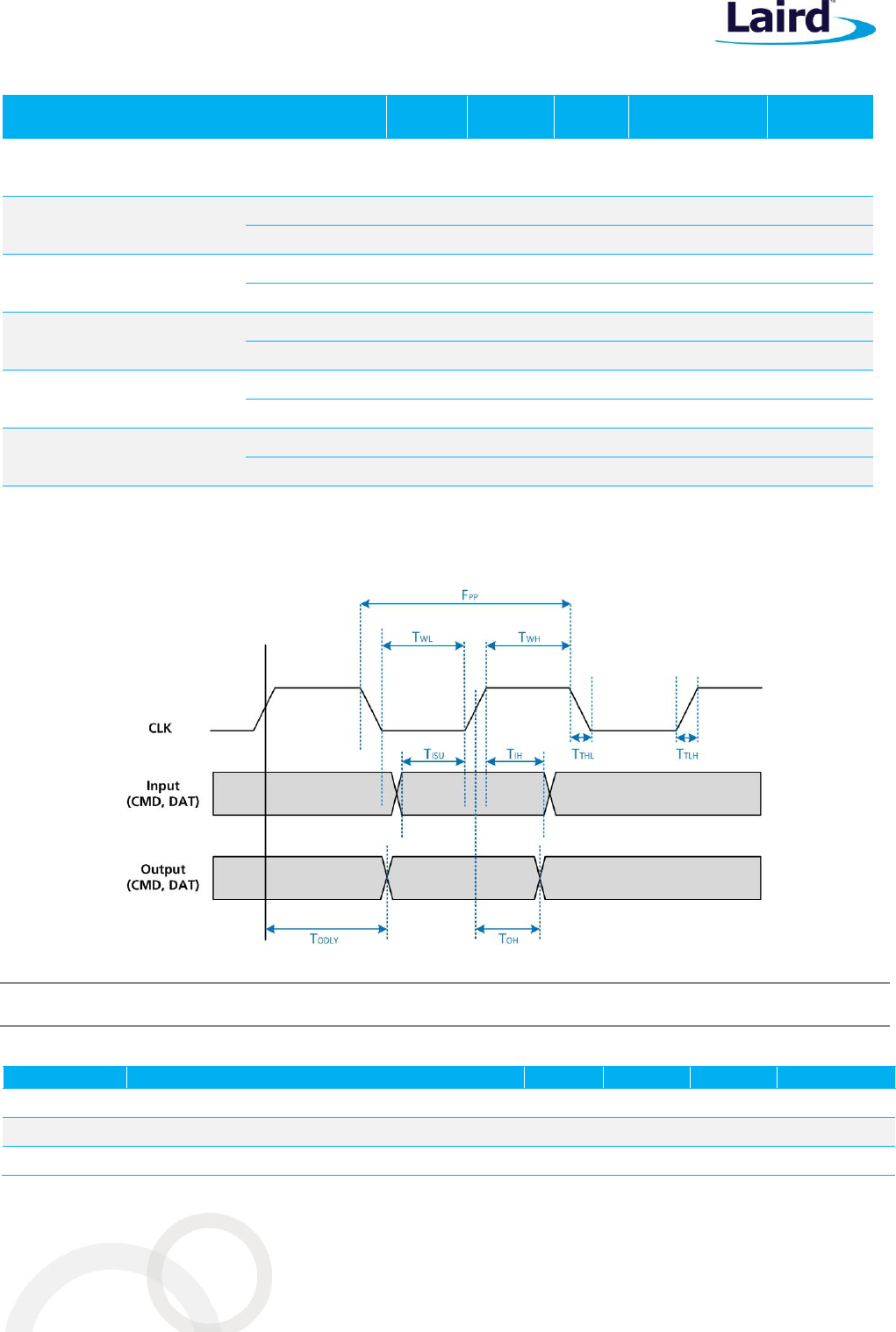
SDIO TIMING REQUIREMENTS
The following figure (Figure 3) and table display SDIO default mode timing.
Figure 3: SDIO Default Mode Timing
Note: Timing is based on CL ≤ 40 pF load on CMD and Data.
Table 17: SDIO Timing Requirements
Symbol
Parameter
Min.
Typ.
Max.
Unit
fPP
Frequency – Data Transfer mode
0
-
50
MHz
tWL
Clock low time
7
-
-
ns
tWH
Clock high time
7
-
-
ns

M2US50NBT/M2SD50NBT
Hardware Integration Guide
Embedded Wireless Solutions Support Center:
http://ews-support.lairdtech.com
www.lairdtech.com/wireless
21
Laird
Americas: +1-800-492-2320
Europe: +44-1628-858-940
Hong Kong: +852-2268-6567 x026
Symbol
Parameter
Min.
Typ.
Max.
Unit
tTLH
Clock rise time
-
-
10
ns
tTHL
Clock low time
-
-
10
ns
Inputs: CMD, DAT (referenced to CLK)
tISU
Input setup time
6
-
-
ns
tIH
Input hold time
2
-
-
ns
Outputs: CMD, DAT (referenced to CLK)
tODLY
Output delay time – Data Transfer mode
0
-
14
ns
PIN DEFINITIONS
Pin #
Name
Type
Voltage
Reference
Description
If Not
Used
1
GND
-
-
Ground
GND
2
3.3Vaux
-
-
3.3V power supply
3.3V
3
USB D+
I/O
-
WLAN USB bus D+
Only used on M2US50NBT
NC
4
3.3Vaux
-
-
3.3V power supply
3.3V
5
USB D-
I/O
-
WLAN USB bus D-
Only used on M2US50NBT
N/C
6
LED#1
-
-
Reserved for Wi-Fi LED indicator,
Active High.
Note: Not supported by current software.
N/C
7
GND
-
-
Ground
GND
8
BT_PCM_CLK
I/O
1.8V
BT PCM clock
N/C
9
SDIO_CLK
I
1.8V
WLAN SDIO clock
Only used for M2SD50NBT.
N/C
10
BT_PCM_SYNC
I/O
1.8V
BT PCM Synchronous data
N/C
11
SDIO_CMD
I
1.8V
WLAN SDIO command data
Only used on M2SD50NBT.
N/C
12
BT_PCM_OUT
O
1.8V
BT PCM synchronous data output
N/C
13
SDIO_DATA0
I/O
1.8V
WLAN SDIO Data0
Only used on M2SD50NBT.
N/C
14
BT_PCM_IN
I
1.8V
BT PCM synchronous data input
N/C
15
SDIO_DATA1
I/O
1.8V
WLAN SDIO Data1
Only used on M2SD50NBT.
N/C
16
LED#2
-
-
N/C
N/C
17
SDIO_DATA2
I/O
1.8V
WLAN SDIO Data2 (used on M2SD50NBT)
N/C
18
GND
-
-
Ground
Ground
19
SDIO_DATA3
I/O
1.8V
WLAN SDIO Data3 (used on M2SD50NBT)
N/C

M2US50NBT/M2SD50NBT
Hardware Integration Guide
Embedded Wireless Solutions Support Center:
http://ews-support.lairdtech.com
www.lairdtech.com/wireless
22
Laird
Americas: +1-800-492-2320
Europe: +44-1628-858-940
Hong Kong: +852-2268-6567 x026
Pin #
Name
Type
Voltage
Reference
Description
If Not
Used
20
BT_UART_WAKE
O
3.3V
Reserved for BT to wakeup Host.
When BT wakes up from its deep sleep
state, it sends an H pulse signal out to Host.
Normally, it is Low state.
N/C
21
Wake on WLAN
O
1.8V
Reserved for Wake-ON-Wireless
(WOW) LAN, WLAN output signal to wake
up host, active Low and already has internal
10K pull up.
Note: Not supported by current software.
N/C
22
BT_UART_TXD
O
1.8V
BT UART transmission data.
N/C
23
WLAN reset
I
1.8V
WLAN reset or power down; Active L
Already has internal 10K pull-up.
Hold this to L to power down the Wi-Fi chip.
N/C
24
Mechanical Key-E
-
-
-
-
25
Mechanical Key-E
-
-
-
-
26
Mechanical Key-E
-
-
-
-
27
Mechanical Key-E
-
-
-
-
28
Mechanical Key-E
-
-
-
-
29
Mechanical Key-E
-
-
-
-
30
Mechanical Key-E
-
-
-
-
31
Mechanical Key-E
-
-
-
-
32
BT_UART_RXD
I
1.8V
BT UART receives data.
N/C
33
GND
-
-
Ground
GND
34
BT_UART_RTS
O
1.8V
BT UART Ready to Send.
N/C
35
N/C
-
-
N/C
N/C
36
BT_UART_CTS
O
1.8V
BT UART Clear to Send.
N/C
37
N/C
-
-
N/C
NC/
38
N/C
-
-
N/C
N/C
39
GND
-
-
Ground
GND
40
N/C
-
-
N/C
N/C
41
N/C
-
-
N/C
N/C
42
N/C
-
-
N/C
N/C
43
N/C
-
-
N/C
N/C
44
LTE_COEX3
I
1.8V
Reserved for LTE coexistence
Note: Not currently supported.
N/C
45
GND
-
-
Ground
GND
46
LTE_ACTIVE
I
1.8V
Reserved for LTE coexistence
Note: Not currently supported.
N/C
47
N/C
-
-
N/C
N/C

M2US50NBT/M2SD50NBT
Hardware Integration Guide
Embedded Wireless Solutions Support Center:
http://ews-support.lairdtech.com
www.lairdtech.com/wireless
23
Laird
Americas: +1-800-492-2320
Europe: +44-1628-858-940
Hong Kong: +852-2268-6567 x026
Pin #
Name
Type
Voltage
Reference
Description
If Not
Used
48
LTE_FRAME_SYNC
I
1.8V
Reserved for LTE coexistence
Note: Not currently supported.
N/C
49
N/C
-
-
N/C
N/C
50
CLK_32K
I
3.3V
32.768KHz slow clock input.
Necessary to put BT into deep sleep mode.
N/C
51
GND
-
-
Ground
GND
52
N/C
-
-
N/C
N/C
53
N/C
-
-
N/C
N/C
54
BT_RFKILL
I
3.3V
Reset BT or to disable BT; Active L
N/C
55
N/C
-
-
N/C
N/C
56
WIFI_RFKILL
I
3.3V
Reserved for RF disable (RF Kill) feature.
Active Low.
Note: Not supported by current software.
N/C
57
GND
-
-
Ground
GND
58
N/C
-
-
N/C
N/C
59
N/C
-
-
N/C
N/C
60
N/C
-
-
N/C
N/C
61
N/C
-
-
N/C
N/C
62
N/C
-
-
N/C
N/C
63
GND
-
-
Ground
GND
64
N/C
-
-
N/C
N/C
65
N/C
-
-
N/C
N/C
66
N/C
-
-
N/C
N/C
67
N/C
-
-
N/C
N/C
78
N/C
-
-
N/C
N/C
69
GND
-
-
Ground
GND
70
N/C
-
-
N/C
N/C
71
N/C
-
-
N/C
N/C
72
3.3Vaux
-
-
3.3V power supply
3.3V
73
N/C
-
-
N/C
N/C
74
3.3Vaux
-
-
3.3V power supply
3.3V
75
GND
-
-
Ground
GND
M2US50NBT/M2SD50NBT
Hardware Integration Guide
Embedded Wireless Solutions Support Center:
http://ews-support.lairdtech.com
www.lairdtech.com/wireless
24
Laird
Americas: +1-800-492-2320
Europe: +44-1628-858-940
Hong Kong: +852-2268-6567 x026
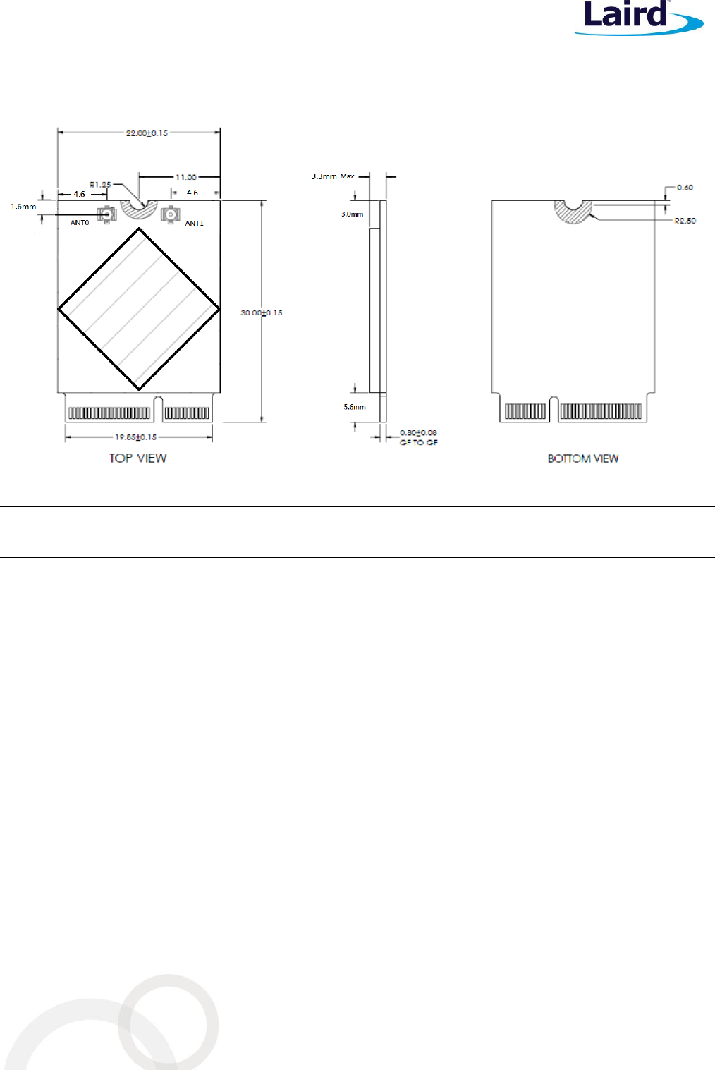
MECHANICAL SPECIFICATIONS
Figure 4: M.2 mechanical drawings
Note: The Wi-Fi MAC address is located on the product label. The BT MAC address is always be numerically
subsequent to the Wi-Fi MAC address. Therefore, the BT MAC address is Wi-Fi MAC address plus one.
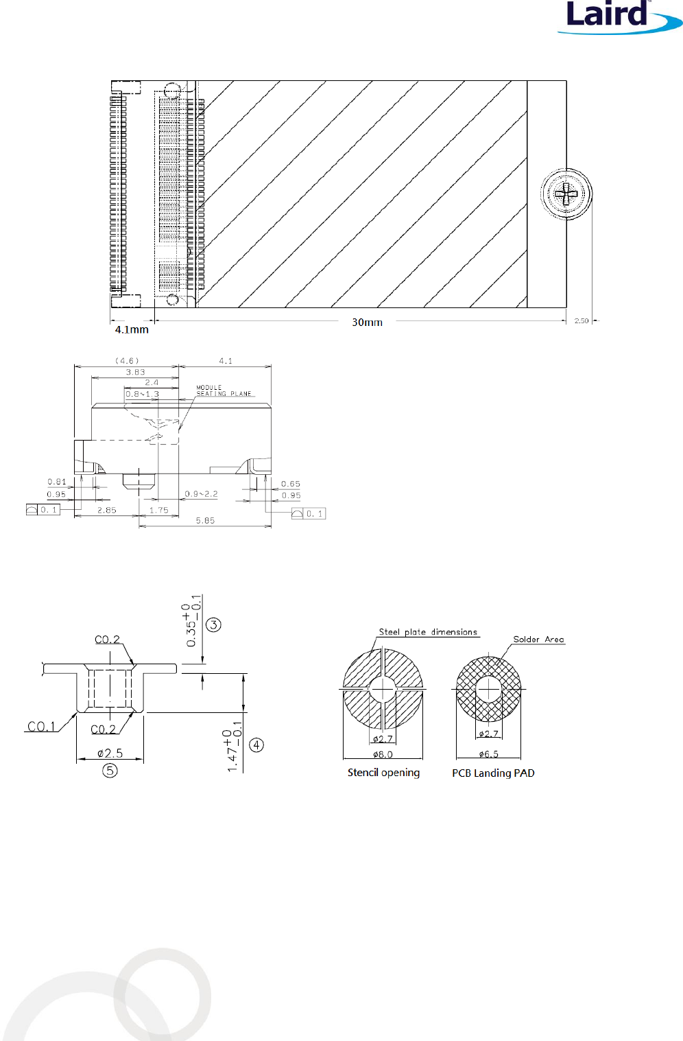
MOUNTING
The M2US50NBT/M2SD50NBT connects to the host via a standard PCI EXPRESS M2 connector.
Kyocera’s (www.Kyocera-connector.com) 6411 series provide 1.8 mm, 2.3 mm and 3.2 mm connector heights.
M2US50NBT/M2SD50NBT is a signal-side component module; Laird recommends part number
24-6411-067-101-897E which has 2.3 mm connector height.
The stand-off mating to the recommend 2.3 mm connector from EMI STOP (www.EMISTOP.com) is part number
F50M16-041525P1D4M. Detail layout and stencil opening are show in Figure 5.
M2US50NBT/M2SD50NBT
Hardware Integration Guide
Embedded Wireless Solutions Support Center:
http://ews-support.lairdtech.com
www.lairdtech.com/wireless
25
Laird
Americas: +1-800-492-2320
Europe: +44-1628-858-940
Hong Kong: +852-2268-6567 x026
Figure 5: Mounting information for M2US50NBT/M2SD50NBT and recommended land pad for stand-off
M2US50NBT/M2SD50NBT
Hardware Integration Guide
Embedded Wireless Solutions Support Center:
http://ews-support.lairdtech.com
www.lairdtech.com/wireless
26
Laird
Americas: +1-800-492-2320
Europe: +44-1628-858-940
Hong Kong: +852-2268-6567 x026
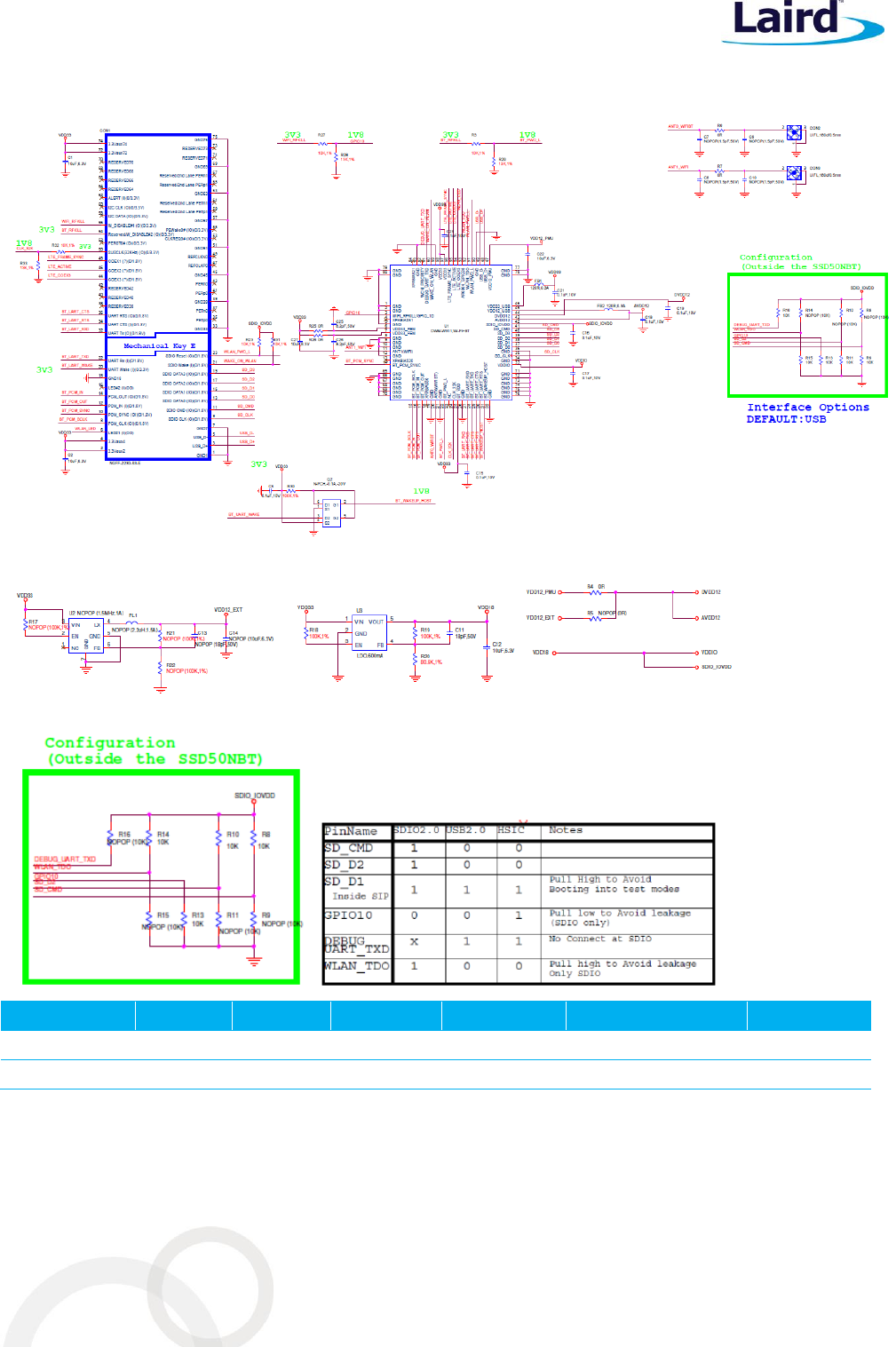
REFERENCE SCHEMATIC OF M2US50NBT
SD_CMD
SD_D2
GPIO-10
WLAN_TDO
DEBUG_UART_TXD
R4/R5
M2US50NBT
L
L
L
L
H
0Ω/NP
M2SD50NBT
H
H
L
H
X
NP/0Ω
M2US50NBT/M2SD50NBT
Hardware Integration Guide
Embedded Wireless Solutions Support Center:
http://ews-support.lairdtech.com
www.lairdtech.com/wireless
27
Laird
Americas: +1-800-492-2320
Europe: +44-1628-858-940
Hong Kong: +852-2268-6567 x026
RF LAYOUT DESIGN GUIDELINES/PRECAUTIONS
The following is a list of RF layout design guidelines and recommendation when installing a Laird radio into your
device.
Do not run antenna cables directly above or directly below the radio.
Do not place any parts or run any high speed digital lines below the radio.
If there are other radios or transmitters located on the device (such as a Bluetooth radio), place the devices
as far apart from each other as possible. Also, make sure there are at least 25dB isolation between
Bluetooth antenna and Wi-Fi antenna.
Laird recommends the use of a double shielded cable for the connection between the radio and the
antenna elements.
Be sure to put the capacitor on the power pin as close as possible to reduce the radiation issue.
Use proper electro-static-discharge (ESD) procedures when installing the Laird radio module.
In order to get maximum throughput when operate at MIMO 2x2, two antennas with at least 25dB isolation
is recommended.
To avoid negatively impacting TX power and receiver sensitivity, do no cover the antennas with metallic
objects or components.
Opening/handing/removing must be done on an anti-ESD treated workbench.
All workers must also have undergone anti-ESD treatment.
The devices should be mounted within one year of the date of delivery.
REGULATORY
Certified Antennas
Model
Type
Connector
2400~2483.5MHz
5150~5250MHz 5250~5350MHz
5470~5725MHz 5725~5850MHz
Laird MAF94051
Dipole
RP-SMA
2.1 dBi (2.4-2.5 GHz), 2.4 dBi (4.9 GHz)
2.6 dBi (5.25 GHz), 3.4 dBi (5.875 GHz)
Laird/NanoBlade-IP04
PCB
Dipole
IPEX MHF
2 dBi (2.4-2.5 GHz),
3.9 dBi (5.15-5.35 GHz), 4 dBi (5.6 GHz)
Laird/MAF95310 Mini Nano Blade
Flex
PCB
Dipole
IPEX MHF
2.79 dBi (2.4 GHz), 3.38 dBi (5 GHz)
Laird/NanoBlue-IP04
PCB
Dipole
IPEX MHF
2 dBi (2.4 GHz only)
Ethertronics/WLAN_1000146
Isolated
Magnetic
Dipole
IPEX MHF
2.5 dBi (2.390-2.490 GHz),
3.5 dBi (4.900-5.100, 5.150-5.350,
5.70-5.900 GHz)
M2US50NBT/M2SD50NBT
Hardware Integration Guide
Embedded Wireless Solutions Support Center:
http://ews-support.lairdtech.com
www.lairdtech.com/wireless
28
Laird
Americas: +1-800-492-2320
Europe: +44-1628-858-940
Hong Kong: +852-2268-6567 x026
FCC AND IC REGULATORY
Model
US/FCC
CANADA/IC
M2US50NBT
M2SD50NBT
SQG-M2US50NBT
SQG-M2SD50NBT
3147A-M2US50NBT
3147A-M2SD50NBT
The M2US50NBT/M2SD50NBT is designed to pass certification with the antenna listed below. The required
antenna impedance is 50 ohms.
Model
Type
Connector
Peak gain ( dBi )
2400~2483.5
MHz
5150~5250
MHz
5250~5350
MHz
5470~5725
MHz
5725~5850
MHz
Laird
MAF94051
Dipole
RP-SMA
2.1 dBi
2.4 dBi
2.6 dBi
3.4 dBi
Laird
NanoBlade-IP04
PCB Dipole
IPEX MHF
2 dBi
3.9 dBi
4 dBi
Laird
MAF95310 Mini
NanoBlade Flex
PCB Dipole
IPEX MHF
2.79 dBi
3.38 dBi
Laird
NanoBlue-IP04
PCB Dipole
IPEX MHF
2dBi
_
Ethertronics
WLAN_1000146
Isolated
Magnetic
Dipole
IPEX MHF
2.5dBi
3.5 dBi
FCC
Federal Communication Commission Interference Statement
This equipment has been tested and found to comply with the limits for a Class B digital device, pursuant to Part
15 of the FCC Rules. These limits are designed to provide reasonable protection against harmful interference in a
residential installation. This equipment generates, uses and can radiate radio frequency energy and, if not
installed and used in accordance with the instructions, may cause harmful interference to radio
communications. However, there is no guarantee that interference will not occur in a particular installation. If
this equipment does cause harmful interference to radio or television reception, which can be determined by
turning the equipment off and on, the user is encouraged to try to correct the interference by one of the
following measures:
Reorient or relocate the receiving antenna.
Increase the separation between the equipment and receiver.
Connect the equipment into an outlet on a circuit different from that to which the receiver is connected.
Consult the dealer or an experienced radio/TV technician for help.
FCC Caution:
Any changes or modifications not expressly approved by the party responsible for compliance could void the
user's authority to operate this equipment.

M2US50NBT/M2SD50NBT
Hardware Integration Guide
Embedded Wireless Solutions Support Center:
http://ews-support.lairdtech.com
www.lairdtech.com/wireless
29
Laird
Americas: +1-800-492-2320
Europe: +44-1628-858-940
Hong Kong: +852-2268-6567 x026
This device complies with Part 15 of the FCC Rules. Operation is subject to the following two conditions: (1) This
device may not cause harmful interference, and (2) this device must accept any interference received, including
interference that may cause undesired operation.
Important Note:
Radiation Exposure Statement
This equipment complies with FCC radiation exposure limits set forth for an uncontrolled environment. This
equipment should be installed and operated with minimum distance 20cm between the radiator and your body.
This transmitter must not be co-located or operating in conjunction with any other antenna or transmitter.
Country Code selection feature to be disabled for products marketed to the US/Canada.
This device is intended only for OEM integrators under the following conditions:
The antenna must be installed such that 20 cm is maintained between the antenna and users, and
The transmitter module may not be co-located with any other transmitter or antenna,
For all products market in US, OEM has to limit the operation channels in CH1 to CH11 for 2.4G band by
supplied firmware programming tool. OEM shall not supply any tool or info to the end-user regarding to
Regulatory Domain change.
As long as the three conditions above are met, further transmitter testing will not be required. However, the
OEM integrator is still responsible for testing their end-product for any additional compliance requirements
required with this module installed.
Important Note:
In the event that these conditions cannot be met (for example certain laptop configurations or co-location with
another transmitter), then the FCC authorization is no longer considered valid and the FCC ID cannot be used on
the final product. In these circumstances, the OEM integrator will be responsible for re-evaluating the end
product (including the transmitter) and obtaining a separate FCC authorization.
End Product Labeling
This transmitter module is authorized only for use in device where the antenna may be installed such that 20 cm
may be maintained between the antenna and users. The final end product must be labeled in a visible area with
the following for the M2US50NBT: Contains FCC ID: SQG-M2US50NBT and for the M2SD50NBT: Contains FCC ID:
SQG-M2SD50NBT.
Manual Information to the End User
The OEM integrator has to be aware not to provide information to the end user regarding how to install or
remove this RF module in the user’s manual of the end product which integrates this module.
The end user manual shall include all required regulatory information/warning as show in this manual.
Industry Canada
Industry Canada Statement
This device complies with Industry Canada’s license-exempt RSSs. Operation is subject to the following two
conditions:
M2US50NBT/M2SD50NBT
Hardware Integration Guide
Embedded Wireless Solutions Support Center:
http://ews-support.lairdtech.com
www.lairdtech.com/wireless
30
Laird
Americas: +1-800-492-2320
Europe: +44-1628-858-940
Hong Kong: +852-2268-6567 x026
This device may not cause interference; and
This device must accept any interference, including interference that may cause undesired operation of
the device.
Le présent appareil est conforme aux CNR d’Industrie Canada applicables aux appareils radio exempts de
licence. L’exploitation est autorisée aux deux conditions suivantes:
l’appareil ne doit pas produire de brouillage;
l’utilisateur de l’appareil doit accepter tout brouillage radioélectrique subi, même si le brouillage est
susceptible d’en compromettre le fonctionnement.
This radio transmitter (M2US50NBT – IC: 3147A-M2US50NBT / M2US50NBT – IC: 3147A-M2SD50NBT) has been
approved by Industry Canada to operate with the antenna types listed below with the maximum permissible
gain indicated. Antenna types not included in this list, having a gain greater than the maximum gain indicated for
that type, are strictly prohibited for use with this device.
Le présent émetteur radio (M2US50NBT – IC: 3147A-M2US50NBT / M2US50NBT – IC: 3147A-M2SD50NBT) a été
approuvé par Industrie Canada pour fonctionner avec les types d'antenne énumérés ci-dessous et ayant un gain
admissible maximal. Les types d'antenne non inclus dans cette liste, et dont le gain est supérieur au gain
maximal indiqué, sont strictement interdits pour l'exploitation de l'émetteur.
Antenna Information
Model
Type
Connector
Peak gain ( dBi )
2400~2483.5
MHz
5150~5250
MHz
5250~5350
MHz
5470~5725
MHz
5725~5850
MHz
Laird
MAF94051
Dipole
RP-SMA
2.1 dBi
2.4 dBi
2.6 dBi
3.4 dBi
Laird
NanoBlade-IP04
PCB Dipole
IPEX MHF
2 dBi
3.9 dBi
4 dBi
Laird
MAF95310 Mini
NanoBlade Flex
PCB Dipole
IPEX MHF
2.79 dBi
3.38 dBi
Laird
NanoBlue-IP04
PCB Dipole
IPEX MHF
2dBi
_
Ethertronics
WLAN_1000146
Isolated
Magnetic
Dipole
IPEX MHF
2.5dBi
3.5 dBi
Caution:
(i) The device for operation in the band 5150–5250 MHz is only for indoor use to reduce the potential for
harmful interference to co-channel mobile satellite systems;
(ii) For devices with detachable antenna(s), the maximum antenna gain permitted for devices in the bands 5250-
5350 MHz and 5470-5725 MHz shall be such that the equipment still complies with the EIRP limit;
(iii) For devices with detachable antenna(s), the maximum antenna gain permitted for devices in the band 5725-
5850 MHz shall be such that the equipment still complies with the EIRP limits specified for point-to-point and
non-point-to-point operation as appropriate; and

M2US50NBT/M2SD50NBT
Hardware Integration Guide
Embedded Wireless Solutions Support Center:
http://ews-support.lairdtech.com
www.lairdtech.com/wireless
31
Laird
Americas: +1-800-492-2320
Europe: +44-1628-858-940
Hong Kong: +852-2268-6567 x026
Operations in the 5.25-5.35GHz band are restricted to indoor usage only.
Avertissement:
(i) les dispositifs fonctionnant dans la bande de 5150 à 5250MHz sont réservés uniquement pour une utilisation
à l'intérieur afin de réduire les risques de brouillage préjudiciable aux systèmes de satellites mobiles utilisant les
mêmes canaux;
(ii) pour les dispositifs munis d'antennes amovibles, le gain maximal d'antenne permis pour les dispositifs
utilisant les bandes de 5250 à 5350MHz et de 5470 à 5725 MHz doit être conforme à la limite de la p.i.r.e;
(iii) pour les dispositifs munis d'antennes amovibles, le gain maximal d'antenne permis (pour les dispositifs
utilisant la bande de 5725 à 5850 MHz) doit être conforme à la limite de la p.i.r.e. spécifiée pour l'exploitation
point à point et l'exploitation non point à point, selon le cas;
Les opérations dans la bande de 5.25-5.35GHz sont limités à un usage intérieur seulement.
Radiation Exposure Statement
This equipment complies with Canada radiation exposure limits set forth for an uncontrolled environment. This
equipment should be installed and operated with minimum distance 20cm between the radiator & your body.
Déclaration d'exposition aux radiations
Cet équipement est conforme Canada limites d'exposition aux radiations dans un environnement non contrôlé.
Cet équipement doit être installé et utilisé à distance minimum de 20cm entre le radiateur et votre corps.
This device is intended only for OEM integrators under the following condition:
The transmitter module may not be co-located with any other transmitter or antenna.
As long as the condition above is met, further transmitter test will not be required. However, the OEM
integrator is still responsible for testing their end-product for any additional compliance requirements required
with this module installed.
Cet appareil est conçu uniquement pour les intégrateurs OEM dans les conditions suivantes:
Le module émetteur peut ne pas être coïmplanté avec un autre émetteur ou antenne.
Tant que les 1 condition ci-dessus sont remplies, des essais supplémentaires sur l'émetteur ne seront pas
nécessaires. Toutefois, l'intégrateur OEM est toujours responsable des essais sur son produit final pour toutes
exigences de conformité supplémentaires requis pour ce module installé.
Important Note:
In the event that these conditions cannot be met (for example certain laptop configurations or co-location with
another transmitter), then the Canada authorization is no longer considered valid and the IC ID cannot be used
on the final product. In these circumstances, the OEM integrator will be responsible for re-evaluating the end
product (including the transmitter) and obtaining a separate Canada authorization.
Note Importante:
Dans le cas où ces conditions ne peuvent être satisfaites (par exemple pour certaines configurations
d'ordinateur portable ou de certaines co-localisation avec un autre émetteur), l'autorisation du Canada n'est
plus considéré comme valide et l'ID IC ne peut pas être utilisé sur le produit final. Dans ces circonstances,
M2US50NBT/M2SD50NBT
Hardware Integration Guide
Embedded Wireless Solutions Support Center:
http://ews-support.lairdtech.com
www.lairdtech.com/wireless
32
Laird
Americas: +1-800-492-2320
Europe: +44-1628-858-940
Hong Kong: +852-2268-6567 x026
l'intégrateur OEM sera chargé de réévaluer le produit final (y compris l'émetteur) et l'obtention d'une
autorisation distincte au Canada.
End Product Labeling
The final end product must be labeled in a visible area with the following for the M2US50NBT: Contains IC:
3147A-M2US50NBT and for the M2SD50NBT: Contains IC: 3147A-M2SD50NBT.
Plaque signalétique du produit final
Le produit final doit être étiqueté dans un endroit visible avec l'inscription suivante: M2US50NBT – Contient des
IC: 3147A-M2US50NBT; M2SD50NBT – Contains IC: 3147A-M2SD50NBT.
Manual Information to the End User
The OEM integrator has to be aware not to provide information to the end user regarding how to install or
remove this RF module in the user’s manual of the end product which integrates this module.
The end user manual shall include all required regulatory information/warning as show in this manual.
Manuel d'information à l'utilisateur final
L'intégrateur OEM doit être conscient de ne pas fournir des informations à l'utilisateur final quant à la façon
d'installer ou de supprimer ce module RF dans le manuel de l'utilisateur du produit final qui intègre ce module.
Le manuel de l'utilisateur final doit inclure toutes les informations réglementaires requises et avertissements
comme indiqué dans ce manuel.
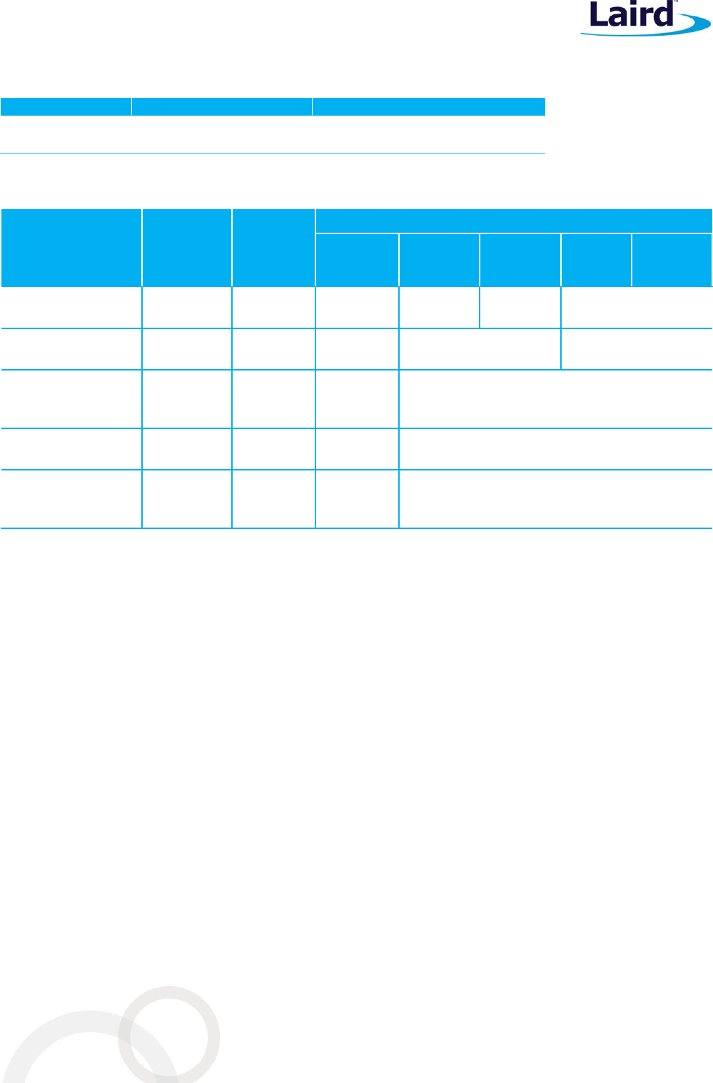
EUROPEAN UNION REGULATORY
The M2US50NBT/M2SD50NBT has been tested for compliance with relevant standards for the EU market.
M2US50NBT/M2SD50NBT module was tested with antennas listed below.
Model
Type
Connector
2400~2483.5MHz
5150~5250MHz 5250~5350MHz
5470~5725MHz 5725~5850MHz
Laird MAF94051
Dipole
RP-SMA
2.1 dBi (2.4-2.5 GHz), 2.4 dBi (4.9 GHz)
2.6 dBi (5.25 GHz), 3.4 dBi (5.875 GHz)
Laird/NanoBlade-IP04
PCB
Dipole
IPEX MHF
2 dBi (2.4-2.5 GHz),
3.9 dBi (5.15-5.35 GHz), 4 dBi (5.6 GHz)
Laird/MAF95310 Mini Nano Blade
Flex
PCB
Dipole
IPEX MHF
2.79 dBi (2.4 GHz), 3.38 dBi (5 GHz)
Laird/NanoBlue-IP04
PCB
Dipole
IPEX MHF
2 dBi (2.4 GHz only)
Ethertronics/WLAN_1000146
Isolated
Magnetic
Dipole
IPEX MHF
2.5 dBi (2.390-2.490 GHz),
3.5 dBi (4.900-5.100, 5.150-5.350,
5.70-5.900 GHz)
The OEM should consult with a qualified test house before entering their device into an EU member country to
make sure all regulatory requirements have been met for their complete device.

M2US50NBT/M2SD50NBT
Hardware Integration Guide
Embedded Wireless Solutions Support Center:
http://ews-support.lairdtech.com
www.lairdtech.com/wireless
33
Laird
Americas: +1-800-492-2320
Europe: +44-1628-858-940
Hong Kong: +852-2268-6567 x026
Reference the Declaration of Conformities listed below for a full list of the standards that the modules were
tested to. Test reports are available upon request.
EU DECLARATIONS OF CONFORMITY
M2US50NBT/M2SD50NBT
Manufacturer:
Laird
Product:
M2US50NBT/M2SD50NBT
EU Directive:
RTTE 1995/5/EC
Conformity Assessment:
Annex IV
Reference standards used for presumption of conformity:
Article Number
Requirement
Reference standard(s)
3.1a
Health and Safety
EN60950-1:2006+A11:2009+A1:2010+A12:2011
3.1b
Protection requirements with
respect to electromagnetic
compatibility
EN 301 489-1 V1.9.2 (2011-09)
EN 301 489-17 V2.2.1 (2012-09)
Emissions:
EN55022:2006/A1:2007 (Class B)
Immunity:
EN61000-4-2:2009
EN61000-4-3:2006/A1:2008/A2:2010
3.2
Means of the efficient use of the
radio frequency spectrum
EN 300 328 V1.8.1 (2012-06)
EN 301 893 v1.8.1
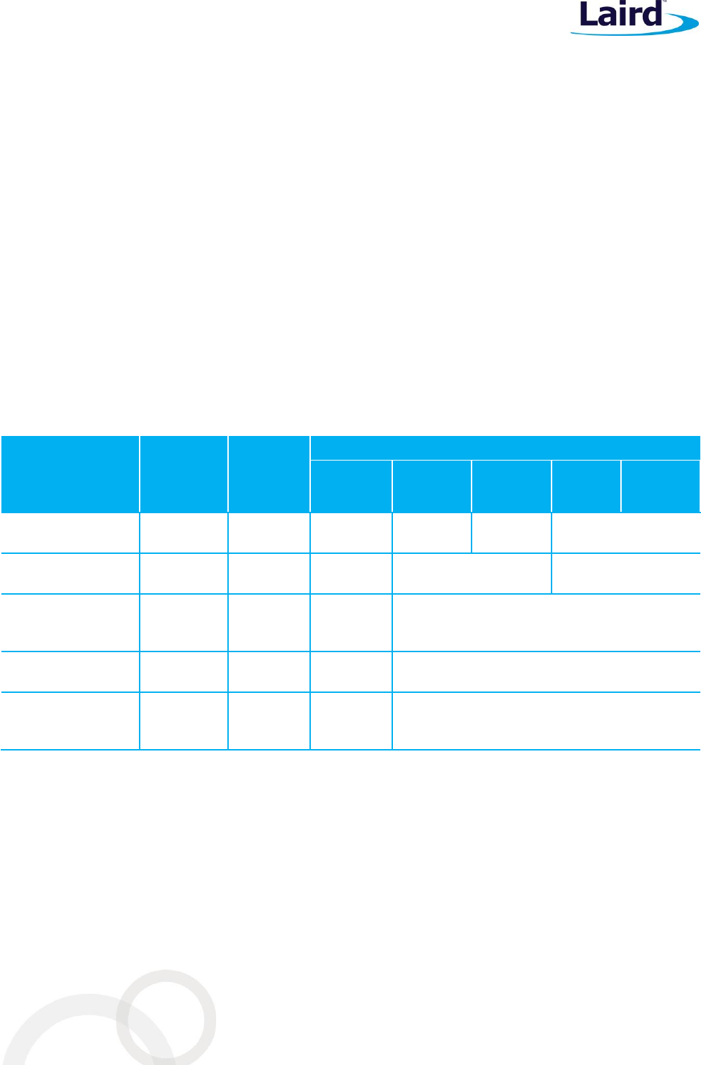
ORDERING INFORMATION
Part Number
Description
M2US50NBT
2X2 802.11 a/b/g/n with BT4.0 dual mode module.
WLAN run at USB bus. BT run at UART/PCM
M2SD50NBT
2X2 802.11 a/b/g/n with BT4.0 dual mode module.
WLAN run at SDIO bus. BT run at UART/PCM
General Comments
This is a preliminary datasheet. Please check with Laird for the latest information before commencing a design. If
in doubt, ask.
Česky
[Czech]
[Jméno výrobce] tímto prohlašuje, že tento [typ zařízení] je ve shodě se základními požadavky
a dalšími příslušnými ustanoveními směrnice 1999/5/ES.
Dansk
[Danish]
Undertegnede [fabrikantens navn] erklærer herved, at følgende udstyr [udstyrets
typebetegnelse] overholder de væsentlige krav og øvrige relevante krav i direktiv 1999/5/EF.
Deutsch
[German]
Hiermit erklärt [Name des Herstellers], dass sich das Gerät [Gerätetyp] in Übereinstimmung
mit den grundlegenden Anforderungen und den übrigen einschlägigen Bestimmungen der
Richtlinie 1999/5/EG befindet.
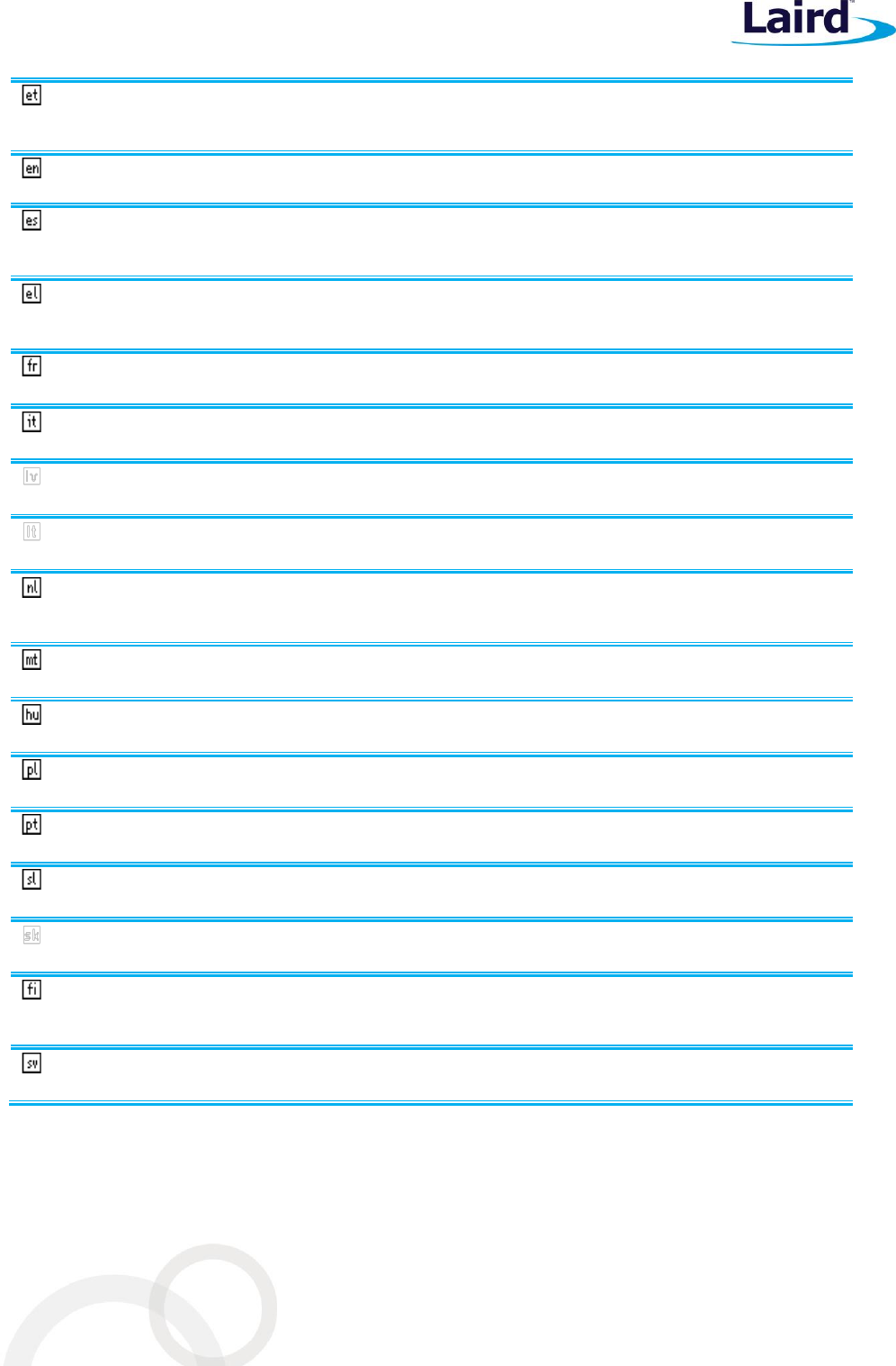
M2US50NBT/M2SD50NBT
Hardware Integration Guide
Embedded Wireless Solutions Support Center:
http://ews-support.lairdtech.com
www.lairdtech.com/wireless
34
Laird
Americas: +1-800-492-2320
Europe: +44-1628-858-940
Hong Kong: +852-2268-6567 x026
Eesti
[Estonian]
Käesolevaga kinnitab [tootja nimi = name of manufacturer] seadme [seadme tüüp = type of
equipment] vastavust direktiivi 1999/5/EÜ põhinõuetele ja nimetatud direktiivist tulenevatele
teistele asjakohastele sätetele.
English
Hereby, [name of manufacturer], declares that this [type of equipment] is in compliance with
the essential requirements and other relevant provisions of Directive 1999/5/EC.
Español
[Spanish]
Por medio de la presente [nombre del fabricante] declara que el [clase de equipo] cumple con
los requisitos esenciales y cualesquiera otras disposiciones aplicables o exigibles de la Directiva
1999/5/CE.
Ελληνική
[Greek]
ΜΕ ΤΗΝ ΠΑΡΟΥΣΑ [name of manufacturer] ΔΗΛΩΝΕΙ ΟΤΙ [type of equipment]
ΣΥΜΜΟΡΦΩΝΕΤΑΙ ΠΡΟΣ ΤΙΣ ΟΥΣΙΩΔΕΙΣ ΑΠΑΙΤΗΣΕΙΣ ΚΑΙ ΤΙΣ ΛΟΙΠΕΣ ΣΧΕΤΙΚΕΣ
ΔΙΑΤΑΞΕΙΣ ΤΗΣ ΟΔΗΓΙΑΣ 1999/5/ΕΚ.
Français
[French]
Par la présente [nom du fabricant] déclare que l'appareil [type d'appareil] est conforme aux
exigences essentielles et aux autres dispositions pertinentes de la directive 1999/5/CE.
Italiano
[Italian]
Con la presente [nome del costruttore] dichiara che questo [tipo di apparecchio] è conforme ai
requisiti essenziali ed alle altre disposizioni pertinenti stabilite dalla direttiva 1999/5/CE.
Latviski
[Latvian]
Aršo[name of manufacturer /izgatavotājanosaukums] deklarē, ka[type of equipment / iekārtas
tips]atbilstDirektīvas 1999/5/EK būtiskajāmprasībām un citiemar to saistītajiemnoteikumiem.
Lietuvių
[Lithuanian]
Šiuo [manufacturer name] deklaruoja, kad šis [equipment type] atitinka esminius reikalavimus
ir kitas 1999/5/EB Direktyvos nuostatas.
Nederlands
[Dutch]
Hierbij verklaart [naam van de fabrikant] dat het toestel [type van toestel] in overeenstemming
is met de essentiële eisen en de andere relevante bepalingen van richtlijn 1999/5/EG.
Malti
[Maltese]
Hawnhekk, [isem tal-manifattur], jiddikjara li dan [il-mudel tal-prodott] jikkonforma mal-
ħtiġijiet essenzjali u ma provvedimenti oħrajn relevanti li hemm fid-Dirrettiva 1999/5/EC.
Magyar
[Hungarian]
Alulírott, [gyártó neve] nyilatkozom, hogy a [... típus]megfelel a vonatkozó alapvetõ
követelményeknek és az 1999/5/EC irányelv egyéb elõírásainak.
Polski
[Polish]
Niniejszym [nazwa producenta] oświadcza, że [nazwa wyrobu] jest zgodny z zasadniczymi
wymogami oraz pozostałymi stosownymi postanowieniami Dyrektywy 1999/5/EC.
Português
[Portuguese]
[Nome do fabricante] declara que este [tipo de equipamento] está conforme com os requisitos
essenciais e outras disposições da Directiva 1999/5/CE.
Slovensko
[Slovenian]
[Ime proizvajalca] izjavlja, da je ta [tip opreme] v skladu z bistvenimi zahtevami in ostalimi
relevantnimi določili direktive 1999/5/ES.
Slovensky
[Slovak]
[Menovýrobcu]týmtovyhlasuje, že[typzariadenia]spĺňazákladnépožiadavky a
všetkypríslušnéustanoveniaSmernice 1999/5/ES.
Suomi
[Finnish]
[Valmistaja = manufacturer] vakuuttaa täten että [type of equipment = laitteen tyyppimerkintä]
tyyppinen laite on direktiivin 1999/5/EY oleellisten vaatimusten ja sitä koskevien direktiivin
muiden ehtojen mukainen.
Svenska
[Swedish]
Härmed intygar [företag] att denna [utrustningstyp] står I överensstämmelse med de väsentliga
egenskapskrav och övriga relevanta bestämmelser som framgår av direktiv 1999/5/EG.
Labeling Requirements
The final end product must be labeled in a visible area with the following notice: