Laird Connectivity PKLR2400-200 PKLR2400-200 User Manual exb22
AeroComm Corporation PKLR2400-200 exb22
UserManual.wiki
>
Laird Connectivity
>
PKLR2400-200 User Manual
>
revised users manual please remove the other
Contents
1.
revised users manual please remove the other
2.
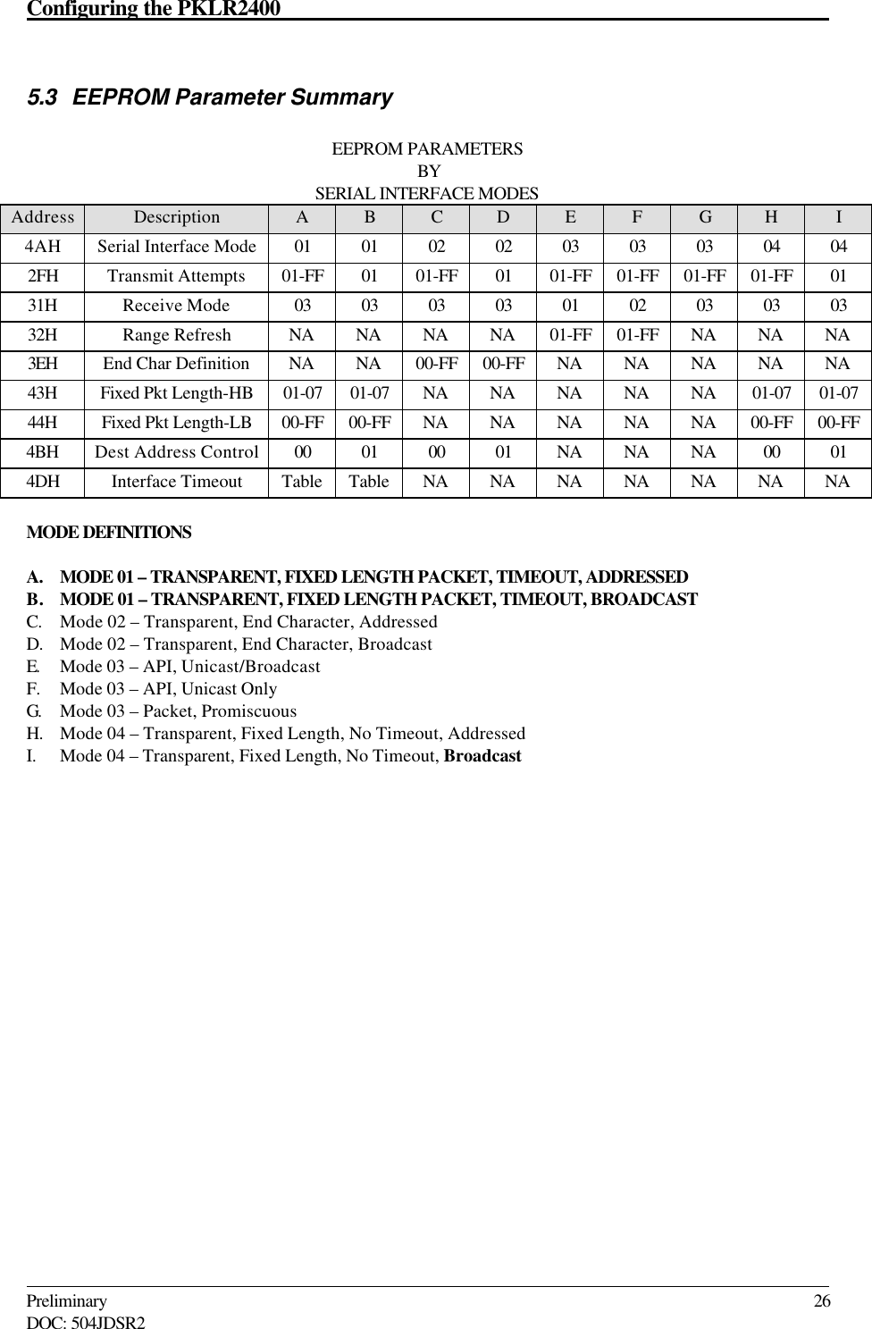
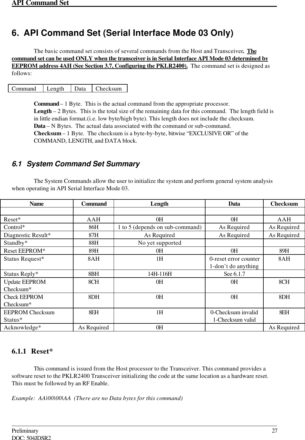
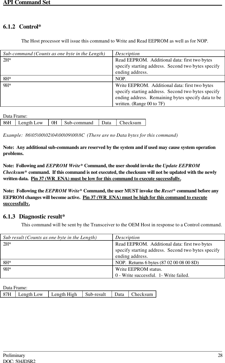
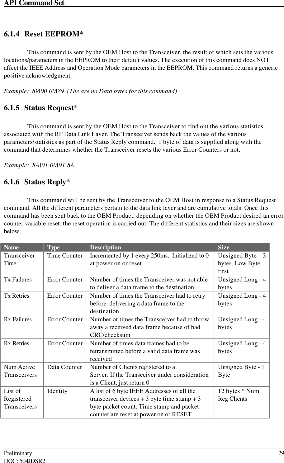
users manual
revised users manual please remove the other
Navigation menu
Upload a User Manual
Namespaces
Wiki Guide
HTML
PDF
Info
Views
User Manual
Discussion / Help
Navigation