Laird Connectivity PKLR2400-200 Frequency Hopping Spread Spectrum Transceiver Modu User Manual Aerocomm OEM Radio
AeroComm Corporation Frequency Hopping Spread Spectrum Transceiver Modu Aerocomm OEM Radio
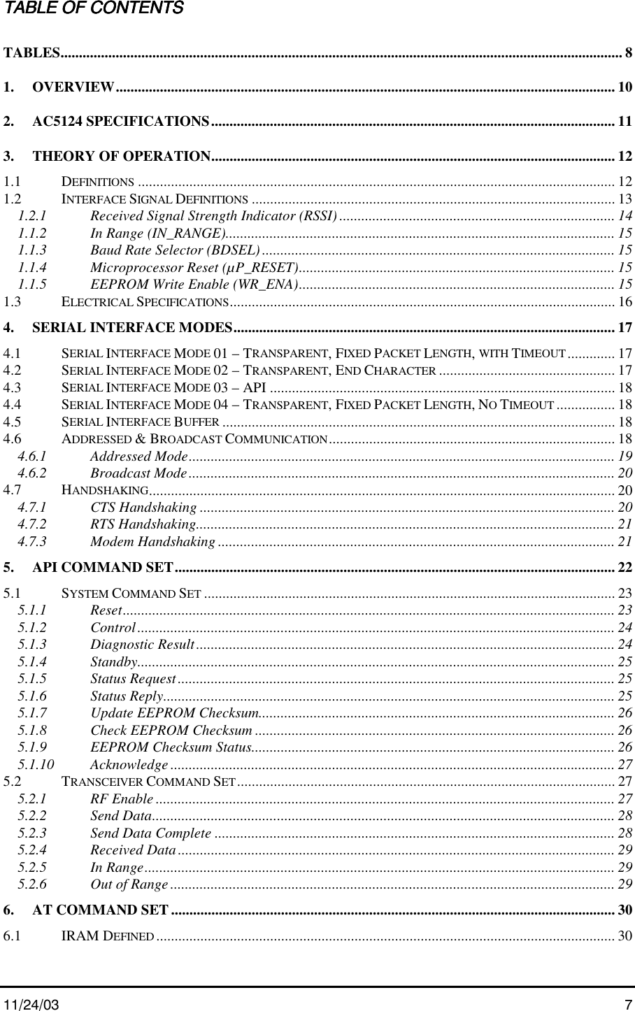
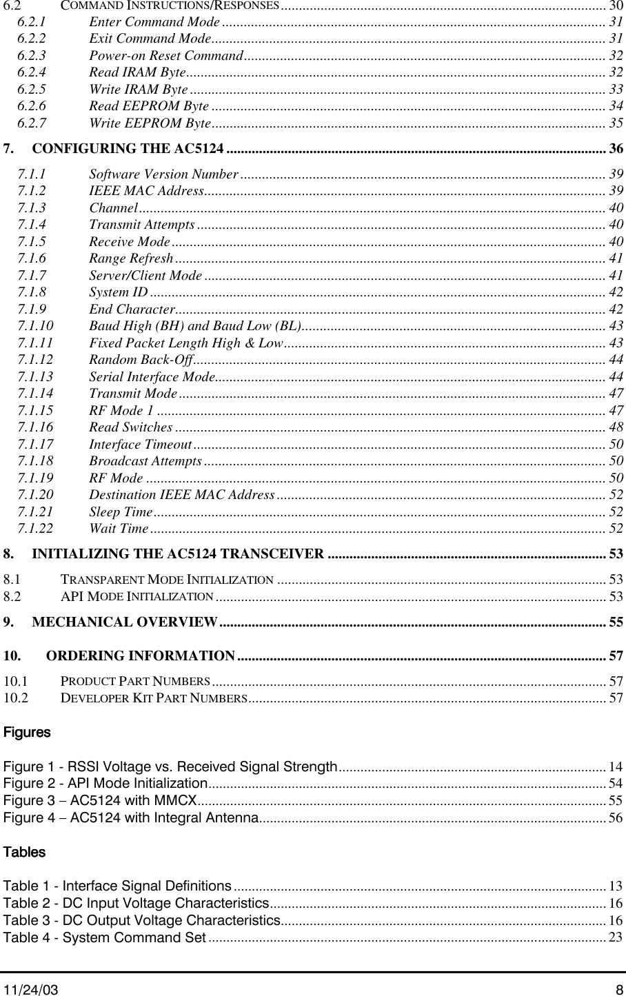
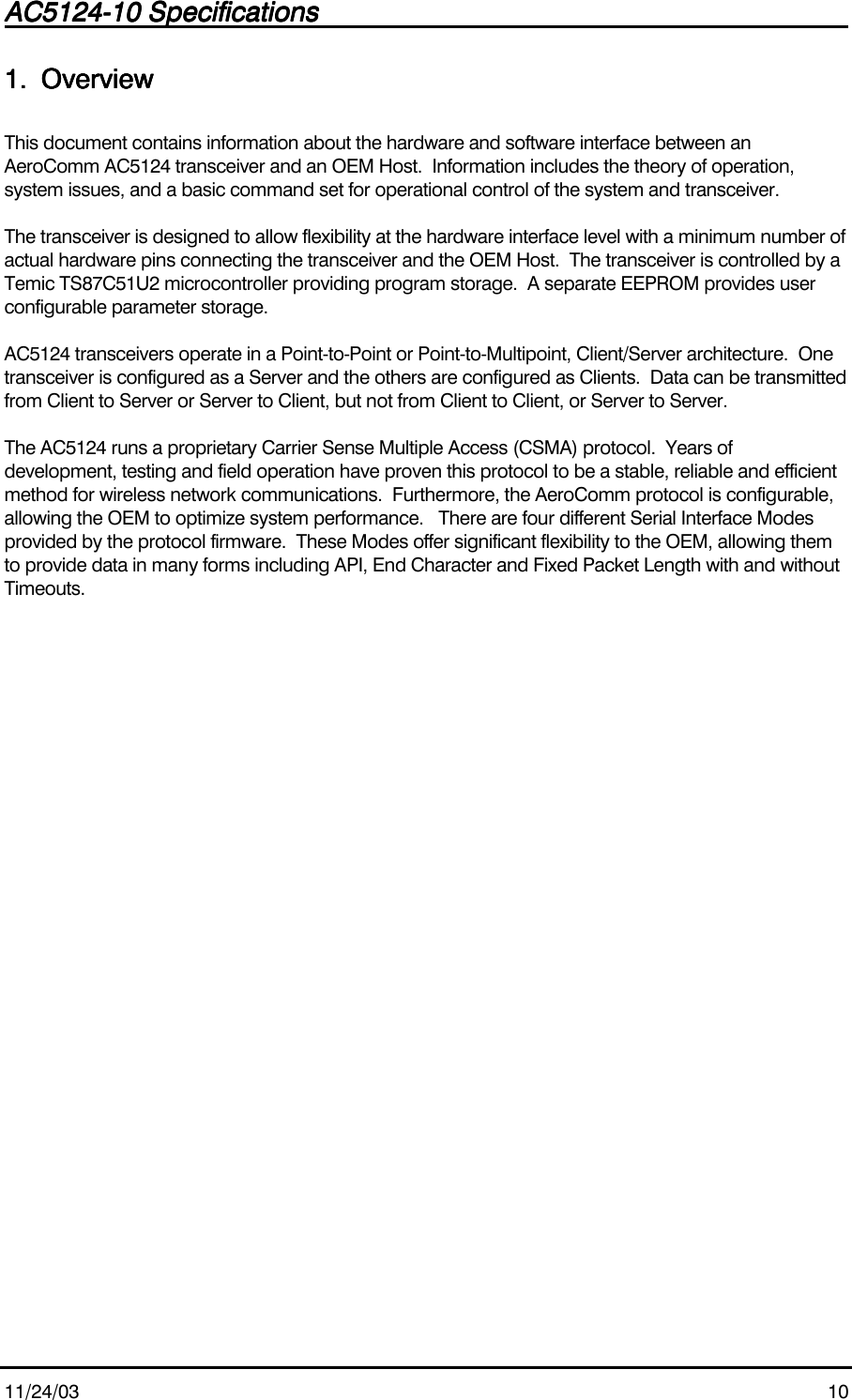
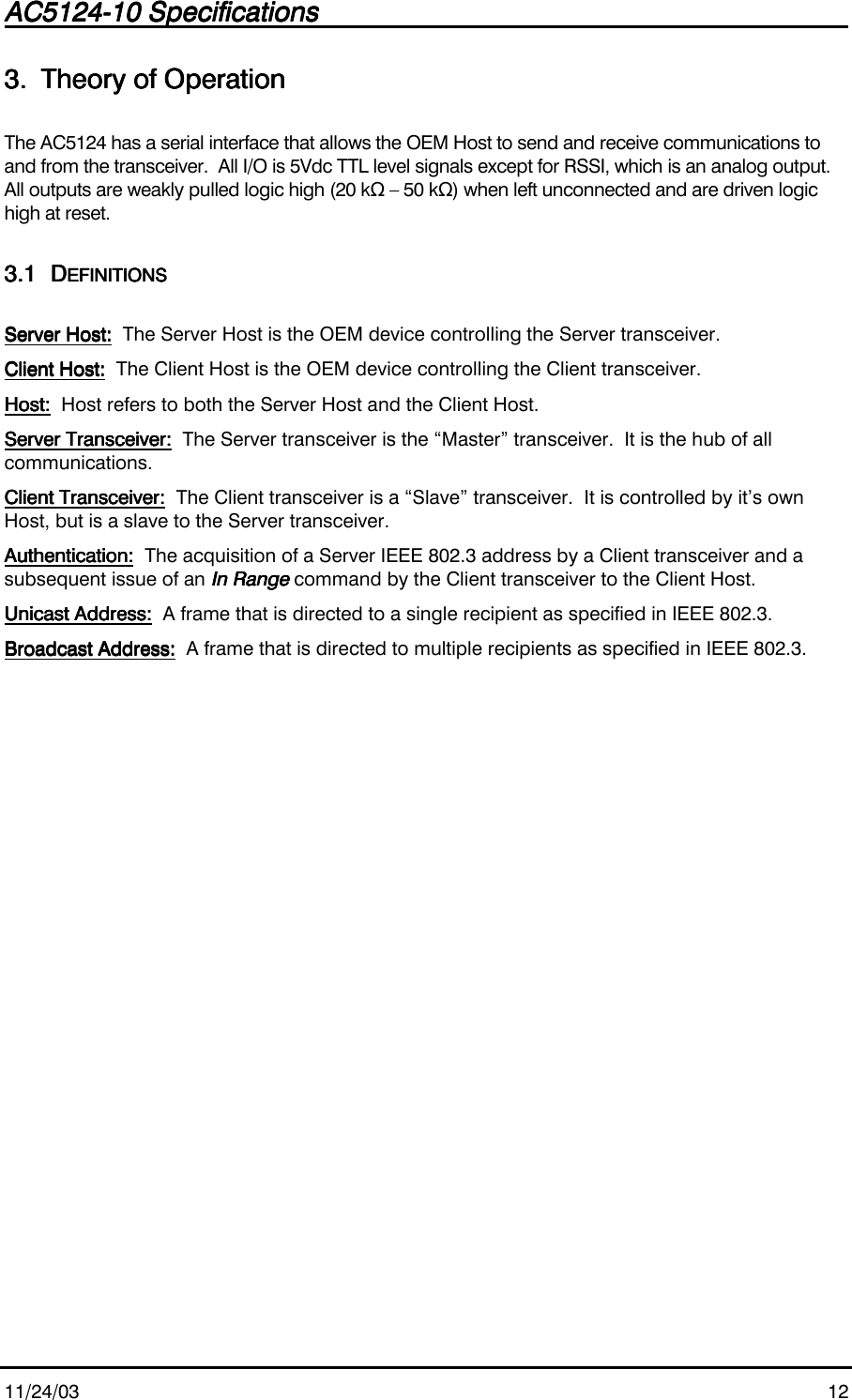
Contents
- 1. revised users manual please remove the other
- 2. users manual
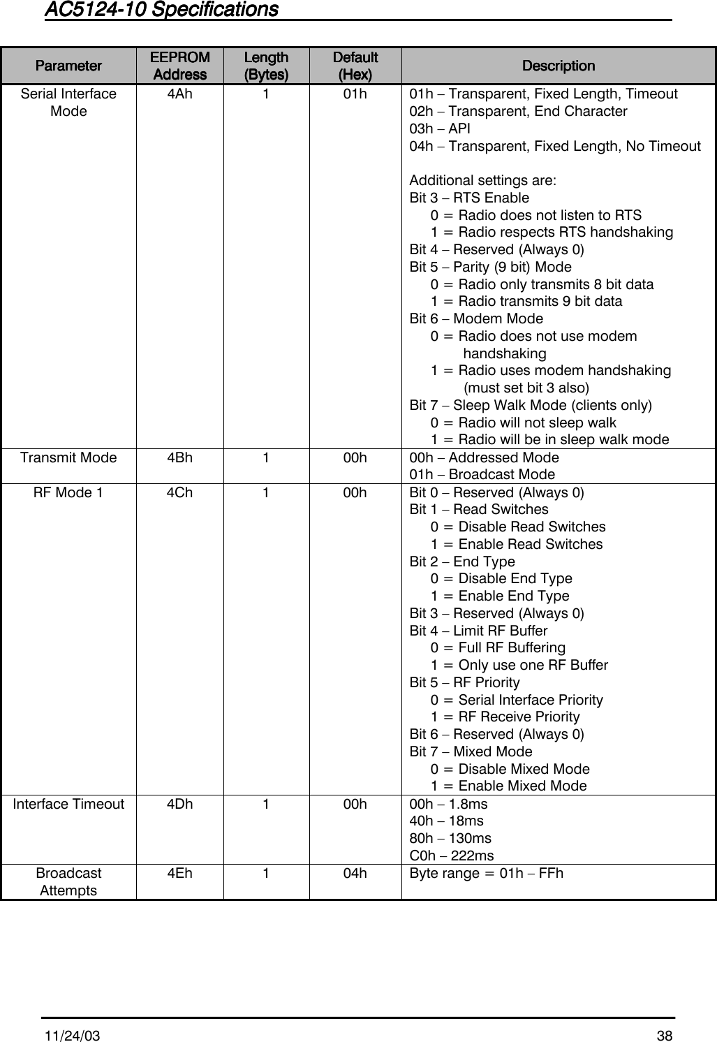
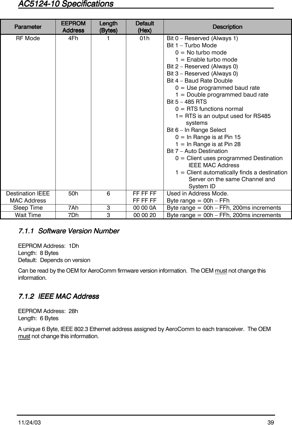
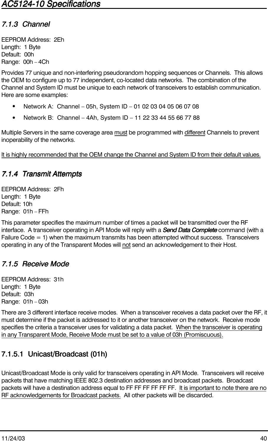
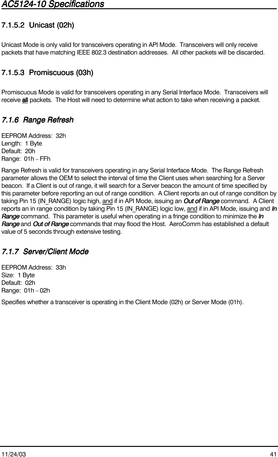
users manual