Laird Connectivity PKLR2400-200 Frequency Hopping Spread Spectrum Transceiver Modu User Manual Aerocomm OEM Radio
AeroComm Corporation Frequency Hopping Spread Spectrum Transceiver Modu Aerocomm OEM Radio
Contents
- 1. revised users manual please remove the other
- 2. users manual
users manual
AC5124
AC5124AC5124
AC5124
2.4 GHz OEM TRANSCEIVER
2.4 GHz OEM TRANSCEIVER2.4 GHz OEM TRANSCEIVER
2.4 GHz OEM TRANSCEIVER
Specifications Subject to Change
Specifications Subject to ChangeSpecifications Subject to Change
Specifications Subject to Change
User’s Manual
User’s ManualUser’s Manual
User’s Manual
Version 4.4
Version 4.4Version 4.4
Version 4.4
10981 EICHER DRIVE
10981 EICHER DRIVE10981 EICHER DRIVE
10981 EICHER DRIVE
LENEXA, KS 66219
LENEXA, KS 66219LENEXA, KS 66219
LENEXA, KS 66219
(800) 492-2320
(800) 492-2320(800) 492-2320
(800) 492-2320
www.aerocomm.com
www.aerocomm.comwww.aerocomm.com
www.aerocomm.com
wireless@aerocomm.com
wireless@aerocomm.comwireless@aerocomm.com
wireless@aerocomm.com

11/24/03 2
DOCUMENT INFORMATION
DOCUMENT INFORMATIONDOCUMENT INFORMATION
DOCUMENT INFORMATION
Copyright
CopyrightCopyright
Copyright
Information
InformationInformation
Information
Copyright © 2000 AEROCOMM, Inc. All rights reserved.
The information contained in this manual and the accompanying
software programs are copyrighted and all rights are reserved by
AEROCOMM, Inc. AEROCOMM, Inc. reserves the right to make
periodic modifications of this product without obligation to notify
any person or entity of such revision. Copying, duplicating, selling, or otherwise
distributing any part of this product without the prior consent of an authorized
representative of AEROCOMM, Inc. is prohibited.
All brands and product names in this publication are registered
trademarks or trademarks of their respective holders.
This material is preliminary
This material is preliminaryThis material is preliminary
This material is preliminary
Information furnished by AEROCOMM in this specification is believed to be accurate. Devices sold
by AEROCOMM are covered by the warranty and patent indemnification provisions appearing in its
Terms of Sale only. AEROCOMM makes no warranty, express, statutory, and implied or by
description, regarding the information set forth herein. AEROCOMM reserves the right to change
specifications at any time and without notice.
AEROCOMM’s products are intended for use in normal commercial applications. Applications
requiring extended temperature range or unusual environmental requirements such as military,
medical life-support or life-sustaining equipment are specifically not recommended without
additional testing for such application.

11/24/03 3
DOCUMENT INFORMATION
DOCUMENT INFORMATIONDOCUMENT INFORMATION
DOCUMENT INFORMATION
Revision
RevisionRevision
Revision Description
DescriptionDescription
Description
Version 3.6 Remove SDK developer kit information – 6/6/00
Re-arrange the layout of the specification to ease use
Correct Channels from 75 to 77 and provide range in Hex, Section 5.1.3
Version 3.7 6/28/00 – Made data rates uniform at 882 Kbps
Reformat I/O table to view additional line descriptions
Version 3.8 8/18/00 – Changed Input Voltage tolerance from 5% to 2%
Changed temperature from 0 – 60 °C to 0 – 70 °C
Changed Baud Low Default from F7 to F1
Updated Section 6 – API Command Set with examples & corrections
Added pin notations on Figure 1 - Mechanical Overview of AC5124C
Version 3.9 9/25/00 – Corrected DTR pin number from 33 to 34, Pin 33 is NC
Changed Pin 24 from Reserved to NC
Remove Note from the CTS timing diagram in Sections 3.3.1 & 4.6
Changed description for Diagnostic Result command in Section 6.1.3
Version 4.2 10/25/01 - Changed PKLR2400S part number to AC5124C
Added AC5124C-200 information
Added Section 3.3, Electrical Specifications
Added RSSI calibration steps in Section 3.2.1
Added Section 4.6, Addressed & Broadcast Communication
Added Section 4.7, Handshaking
Updated Table 6, EEPROM Parameters to include new parameters
Updated Section 5, API Command Set to include command examples
Updated Section 6, Configuring the AC5124C to include new parameter definitions
Added Section 7, Initializing the AC5124C Transceiver
Updated Section 8, Mechanical Overview to include new drawings
Version 4.3 3/25/01 – Changed Interface Timeout values in Table 6, EEPROM Parameters
Updated RF Mode 1 (EEPROM Address 4Ch) to include new definition for Bit 7
Added Section 6.1.15.5, Mixed Mode
Updated Approved Antenna List
Version 4.4 11/24/03 – Updated all references to operating temperature from 0°C to 60°C to -40°C to
80°C. All AC5124 products are industrial temperature. Added AT Commands for
reading and writing the EEPROM. Updated RSSI plot for new receiver IC.
11/24/03 4
FCC INFORMATION
FCC INFORMATIONFCC INFORMATION
FCC INFORMATION
Agency Approval Overview
Agency Approval OverviewAgency Approval Overview
Agency Approval Overview
Part Number
Part NumberPart Number
Part Number US/FCC
US/FCCUS/FCC
US/FCC CAN/IC
CAN/ICCAN/IC
CAN/IC EUR/EN**
EUR/EN**EUR/EN**
EUR/EN** Portable
PortablePortable
Portable Mobile
MobileMobile
Mobile
AC5124-10 X X X X X
AC5124-200 X X X-20cm*
* See RF Exposure warning on page 6
** Does not include France and Spain
Note: The product approvals above are with antennas specified on page 5.
Agency Identification Numbers
Agency Identification NumbersAgency Identification Numbers
Agency Identification Numbers
Part Number
Part NumberPart Number
Part Number US/FCC
US/FCCUS/FCC
US/FCC CAN/IC
CAN/ICCAN/IC
CAN/IC EUR/EN
EUR/ENEUR/EN
EUR/EN
AC5124-10 KQL-PKLR2400 CAN2268391158A X
AC5124-200 KQL-PKLR2400-200 CAN2268391180A
FCC Notice
FCC NoticeFCC Notice
FCC Notice
Antenna Warning
Antenna WarningAntenna Warning
Antenna Warning
WARNING:
WARNING: WARNING:
WARNING: This device complies with Part 15 of the FCC Rules. Operation is subject to the
following two conditions: (1) This device may not cause harmful interference
and (2) This device must accept any interference received, including
interference that may cause undesired operation.
WARNING:
WARNING: WARNING:
WARNING: This device has been tested with an MMCX connector with the antennas listed
below. When integrated in the OEMs product, these fixed antennas require
installation preventing end-users from replacing them with non-approved
antennas. Any antenna not in the following table must be tested to comply with
FCC Section 15.203 for unique antenna connectors and Section 15.247 for
emissions.

11/24/03 5
FCC INFORMATION
FCC INFORMATIONFCC INFORMATION
FCC INFORMATION
Approved Antenna List
Approved Antenna ListApproved Antenna List
Approved Antenna List
Item
ItemItem
Item Part Number
Part NumberPart Number
Part Number Manufacturer
ManufacturerManufacturer
Manufacturer Gain (dBi)
Gain (dBi)Gain (dBi)
Gain (dBi)
AC5124-10
AC5124-10AC5124-10
AC5124-10
AC5124-10A
AC5124-10AAC5124-10A
AC5124-10A
AC5124-200
AC5124-200AC5124-200
AC5124-200
AC5124-200A
AC5124-200AAC5124-200A
AC5124-200A
1 WCP-2400-MMCX Centurion 2 PM M
2 WCR-2400-SMRP Centurion 2 PM
3 MFB24008RPN Maxrad 8 PM
4 BMMG24000MSMARP12’ Maxrad 1 PM
5 BMMG24005MSMARP12’ Maxrad 5 PM
6 MP24013TMSMARP12 Maxrad 13 M
7 MUF24005M174MSMARP12 Maxrad 5 PM
8 MC2400 Maxrad 2.5 M
9 NZH2400-MMCX (External) AeroComm 1 PM M
10 NZH2400-I (Integrated) AeroComm 1 PM M
11 S131CL-5-RMM-2450S Nearson 2 M
12 S181FL-5-RMM-2450S Nearson 2 PM M
13 S191FL-5-RMM-2450S Nearson 3 PM M
14 S151FL-5-RMM-2450S Nearson 5 PM M
15 MLPV1700 Maxrad 4 PM M
P=Portable, M=Mobile
P=Portable, M=MobileP=Portable, M=Mobile
P=Portable, M=Mobile

11/24/03 6
FCC INFORMATION
FCC INFORMATIONFCC INFORMATION
FCC INFORMATION
Labeling Requirements
Labeling RequirementsLabeling Requirements
Labeling Requirements
RF Exposure AC5124-10
RF Exposure AC5124-10RF Exposure AC5124-10
RF Exposure AC5124-10
RF Exposure AC5124-200
RF Exposure AC5124-200RF Exposure AC5124-200
RF Exposure AC5124-200
WARNING:
WARNING: WARNING:
WARNING: The Original Equipment Manufacturer (OEM) must ensure that FCC labeling
requirements are met. This includes a clearly visible label on the outside of the
OEM enclosure specifying the appropriate AeroComm FCC identifier for this
product as well as the FCC Notice above. The FCC identifiers are listed above
in the Agency Identifier Numbers section.
WARNING:
WARNING: WARNING:
WARNING: This equipment has been approved for portable applications where the
equipment can be used in direct contact with the human body. Excessive RF
exposure should be avoided.
The preceding statement must be included as a CAUTION statement in
manuals for products operating with Antennas 3, 4, 5, 6, 7, 14 and 15 in the
previous table to alert users on FCC RF Exposure compliance.
WARNING:
WARNING: WARNING:
WARNING: To satisfy FCC RF exposure requirements for mobile and base station
transmitting devices, a separation distance of 20cm or more should be
maintained between the antenna of this device and persons during operation.
To ensure compliance, operations at closer than this distance is not
recommended.
The preceding statement must be included as a CAUTION statement in
manuals for OEM products to alert users on FCC RF Exposure compliance.

11/24/03 7
TABLE OF CONTENTS
TABLE OF CONTENTSTABLE OF CONTENTS
TABLE OF CONTENTS
TABLES......................................................................................................................................................... 8
1. OVERVIEW........................................................................................................................................ 10
2. AC5124 SPECIFICATIONS.............................................................................................................. 11
3. THEORY OF OPERATION.............................................................................................................. 12
1.1 DEFINITIONS .................................................................................................................................. 12
1.2 INTERFACE SIGNAL DEFINITIONS ................................................................................................... 13
1.2.1 Received Signal Strength Indicator (RSSI) ........................................................................... 14
1.1.2 In Range (IN_RANGE).......................................................................................................... 15
1.1.3 Baud Rate Selector (BDSEL) ................................................................................................ 15
1.1.4 Microprocessor Reset (µP_RESET)...................................................................................... 15
1.1.5 EEPROM Write Enable (WR_ENA)...................................................................................... 15
1.3 ELECTRICAL SPECIFICATIONS......................................................................................................... 16
4. SERIAL INTERFACE MODES........................................................................................................17
4.1 SERIAL INTERFACE MODE 01 – TRANSPARENT, FIXED PACKET LENGTH, WITH TIMEOUT ............. 17
4.2 SERIAL INTERFACE MODE 02 – TRANSPARENT, END CHARACTER ................................................ 17
4.3 SERIAL INTERFACE MODE 03 – API .............................................................................................. 18
4.4 SERIAL INTERFACE MODE 04 – TRANSPARENT, FIXED PACKET LENGTH, NO TIMEOUT ................ 18
4.5 SERIAL INTERFACE BUFFER ........................................................................................................... 18
4.6 ADDRESSED & BROADCAST COMMUNICATION.............................................................................. 18
4.6.1 Addressed Mode.................................................................................................................... 19
4.6.2 Broadcast Mode.................................................................................................................... 20
4.7 HANDSHAKING............................................................................................................................... 20
4.7.1 CTS Handshaking ................................................................................................................. 20
4.7.2 RTS Handshaking.................................................................................................................. 21
4.7.3 Modem Handshaking ............................................................................................................ 21
5. API COMMAND SET........................................................................................................................ 22
5.1 SYSTEM COMMAND SET ................................................................................................................ 23
5.1.1 Reset...................................................................................................................................... 23
5.1.2 Control.................................................................................................................................. 24
5.1.3 Diagnostic Result.................................................................................................................. 24
5.1.4 Standby.................................................................................................................................. 25
5.1.5 Status Request....................................................................................................................... 25
5.1.6 Status Reply........................................................................................................................... 25
5.1.7 Update EEPROM Checksum................................................................................................. 26
5.1.8 Check EEPROM Checksum .................................................................................................. 26
5.1.9 EEPROM Checksum Status................................................................................................... 26
5.1.10 Acknowledge ......................................................................................................................... 27
5.2 TRANSCEIVER COMMAND SET....................................................................................................... 27
5.2.1 RF Enable ............................................................................................................................. 27
5.2.2 Send Data.............................................................................................................................. 28
5.2.3 Send Data Complete ............................................................................................................. 28
5.2.4 Received Data....................................................................................................................... 29
5.2.5 In Range................................................................................................................................ 29
5.2.6 Out of Range......................................................................................................................... 29
6. AT COMMAND SET......................................................................................................................... 30
6.1 IRAM DEFINED ............................................................................................................................. 30

11/24/03 8
6.2 COMMAND INSTRUCTIONS/RESPONSES.......................................................................................... 30
6.2.1 Enter Command Mode.......................................................................................................... 31
6.2.2 Exit Command Mode............................................................................................................. 31
6.2.3 Power-on Reset Command.................................................................................................... 32
6.2.4 Read IRAM Byte.................................................................................................................... 32
6.2.5 Write IRAM Byte................................................................................................................... 33
6.2.6 Read EEPROM Byte ............................................................................................................. 34
6.2.7 Write EEPROM Byte............................................................................................................. 35
7. CONFIGURING THE AC5124 ......................................................................................................... 36
7.1.1 Software Version Number ..................................................................................................... 39
7.1.2 IEEE MAC Address............................................................................................................... 39
7.1.3 Channel................................................................................................................................. 40
7.1.4 Transmit Attempts ................................................................................................................. 40
7.1.5 Receive Mode........................................................................................................................ 40
7.1.6 Range Refresh....................................................................................................................... 41
7.1.7 Server/Client Mode ............................................................................................................... 41
7.1.8 System ID .............................................................................................................................. 42
7.1.9 End Character....................................................................................................................... 42
7.1.10 Baud High (BH) and Baud Low (BL).................................................................................... 43
7.1.11 Fixed Packet Length High & Low......................................................................................... 43
7.1.12 Random Back-Off.................................................................................................................. 44
7.1.13 Serial Interface Mode............................................................................................................ 44
7.1.14 Transmit Mode...................................................................................................................... 47
7.1.15 RF Mode 1 ............................................................................................................................ 47
7.1.16 Read Switches ....................................................................................................................... 48
7.1.17 Interface Timeout.................................................................................................................. 50
7.1.18 Broadcast Attempts ............................................................................................................... 50
7.1.19 RF Mode ............................................................................................................................... 50
7.1.20 Destination IEEE MAC Address ........................................................................................... 52
7.1.21 Sleep Time............................................................................................................................. 52
7.1.22 Wait Time.............................................................................................................................. 52
8. INITIALIZING THE AC5124 TRANSCEIVER ............................................................................. 53
8.1 TRANSPARENT MODE INITIALIZATION ........................................................................................... 53
8.2 API MODE INITIALIZATION ............................................................................................................ 53
9. MECHANICAL OVERVIEW...........................................................................................................55
10. ORDERING INFORMATION...................................................................................................... 57
10.1 PRODUCT PART NUMBERS............................................................................................................. 57
10.2 DEVELOPER KIT PART NUMBERS................................................................................................... 57
Figures
FiguresFigures
Figures
Figure 1 - RSSI Voltage vs. Received Signal Strength.......................................................................... 14
Figure 2 - API Mode Initialization..............................................................................................................54
Figure 3 – AC5124 with MMCX.................................................................................................................55
Figure 4 – AC5124 with Integral Antenna................................................................................................ 56
Tables
TablesTables
Tables
Table 1 - Interface Signal Definitions ....................................................................................................... 13
Table 2 - DC Input Voltage Characteristics............................................................................................. 16
Table 3 - DC Output Voltage Characteristics.......................................................................................... 16
Table 4 - System Command Set ..............................................................................................................23

11/24/03 9
Table 5 - Transceiver Command Set....................................................................................................... 27
Table 6 - EEPROM Parameters ................................................................................................................37
Table 7 - BH/BL Selections For Common Baud Rates .........................................................................43

AC5124-10 Specifications
AC5124-10 SpecificationsAC5124-10 Specifications
AC5124-10 Specifications
11/24/03 10
1.
1.1.
1. Overview
OverviewOverview
Overview
This document contains information about the hardware and software interface between an
AeroComm AC5124 transceiver and an OEM Host. Information includes the theory of operation,
system issues, and a basic command set for operational control of the system and transceiver.
The transceiver is designed to allow flexibility at the hardware interface level with a minimum number of
actual hardware pins connecting the transceiver and the OEM Host. The transceiver is controlled by a
Temic TS87C51U2 microcontroller providing program storage. A separate EEPROM provides user
configurable parameter storage.
AC5124 transceivers operate in a Point-to-Point or Point-to-Multipoint, Client/Server architecture. One
transceiver is configured as a Server and the others are configured as Clients. Data can be transmitted
from Client to Server or Server to Client, but not from Client to Client, or Server to Server.
The AC5124 runs a proprietary Carrier Sense Multiple Access (CSMA) protocol. Years of
development, testing and field operation have proven this protocol to be a stable, reliable and efficient
method for wireless network communications. Furthermore, the AeroComm protocol is configurable,
allowing the OEM to optimize system performance. There are four different Serial Interface Modes
provided by the protocol firmware. These Modes offer significant flexibility to the OEM, allowing them
to provide data in many forms including API, End Character and Fixed Packet Length with and without
Timeouts.

AC5124-10 Specifications
AC5124-10 SpecificationsAC5124-10 Specifications
AC5124-10 Specifications
11/24/03 11
2.
2.2.
2. AC5124 Specifications
AC5124 SpecificationsAC5124 Specifications
AC5124 Specifications
GENERAL
GENERALGENERAL
GENERAL
Bus Interface Serial (TTL Level Asynchronous) through 40 pin mini
connector. AMP P/N 177986-1
Serial Interface Data Rate Programmable to 882 Kbps. PC rates to 115.2 Kbps
Compliance
AC5124-10
Certifiable under:
US (FCC 15.247); Canada (IC); Europe (EN)
AC5124-200 US (FCC 15.247); Canada (IC)
Power Consumption
All Serial Interface Modes
Interface ON/RF OFF (API Mode Only)
Sleep Walk (Clients in all Modes Only)
Deep Sleep (Servers in API Mode Only)
Duty Cycle (TX=Transmit; RX=Receive
Duty Cycle (TX=Transmit; RX=ReceiveDuty Cycle (TX=Transmit; RX=Receive
Duty Cycle (TX=Transmit; RX=Receive)
))
)
25%TX
25%TX25%TX
25%TX
50%TX
50%TX50%TX
50%TX
100%TX
100%TX100%TX
100%TX
100%RX
100%RX100%RX
100%RX
AC5124-10: 111mA 123mA 158mA 100mA
AC5124-200: 185mA 280mA 472mA 110mA
45mA typical
25mA typical
20mA typical
Channels Supports 77 non-interfering channels
Security User assigned System ID. Unique IEEE addresses on each
transceiver.
TRANSCEIVER
TRANSCEIVERTRANSCEIVER
TRANSCEIVER
Frequency Band 2.402 – 2.478 GHz
Transceiver Type Frequency Hopping Spread Spectrum
Output Power
AC5124-10
AC5124-200
10mW
200mW
Input Voltage 5V nominal +2%, + 50mV ripple
Sensitivity -90dBm
RF Data Rate 882 Kbps
Range
AC5124-10
AC5124-200
Can be extended with directional antenna
Indoors up to 300 ft., Outdoors up to 3,000 ft.
Indoors up to 500 ft., Outdoors up to 10,000 ft.
Synchronization Time Average = 750ms; Maximum = 1.5s
ENVIRONMENTAL
ENVIRONMENTALENVIRONMENTAL
ENVIRONMENTAL
Temperature (Operating) -40°C to +80°C
Temperature (Storage) -50°C to +85°C
Humidity (non-condensing) 10% to 90%
PHYSICAL
PHYSICALPHYSICAL
PHYSICAL
Dimensions 1.65” x 2.65” x 0.20”
Antenna Connector Standard MMCX jack
Weight Less than 0.75 ounces
SOFTWARE
SOFTWARESOFTWARE
SOFTWARE
User Configurable Options
Host Interface Data Rate Up to 882 Kbps
Maximum bi-directional throughput Up to 170kbps
Variable Packet Length Up to 2 KBytes
Serial Interface Modes (3) Transparent and (1) API
Diagnostic Error Counters API Mode
User Programmable Attempts Up to 255

AC5124-10 Specifications
AC5124-10 SpecificationsAC5124-10 Specifications
AC5124-10 Specifications
11/24/03 12
3.
3.3.
3. Theory of Operation
Theory of OperationTheory of Operation
Theory of Operation
The AC5124 has a serial interface that allows the OEM Host to send and receive communications to
and from the transceiver. All I/O is 5Vdc TTL level signals except for RSSI, which is an analog output.
All outputs are weakly pulled logic high (20 kΩ – 50 kΩ) when left unconnected and are driven logic
high at reset.
3.1
3.13.1
3.1 D
DD
DEFINITIONS
EFINITIONSEFINITIONS
EFINITIONS
Server Host:
Server Host:Server Host:
Server Host:
The Server Host is the OEM device controlling the Server transceiver.
Client Host:
Client Host:Client Host:
Client Host: The Client Host is the OEM device controlling the Client transceiver.
Host:
Host:Host:
Host: Host refers to both the Server Host and the Client Host.
Server Transceiver:
Server Transceiver:Server Transceiver:
Server Transceiver:
The Server transceiver is the “Master” transceiver. It is the hub of all
communications.
Client Transceiver:
Client Transceiver:Client Transceiver:
Client Transceiver: The Client transceiver is a “Slave” transceiver. It is controlled by it’s own
Host, but is a slave to the Server transceiver.
Authentication:
Authentication:Authentication:
Authentication: The acquisition of a Server IEEE 802.3 address by a Client transceiver and a
subsequent issue of an
In Range
In RangeIn Range
In Range
command by the Client transceiver to the Client Host.
Unicast Address:
Unicast Address:Unicast Address:
Unicast Address: A frame that is directed to a single recipient as specified in IEEE 802.3.
Broadcast Address:
Broadcast Address:Broadcast Address:
Broadcast Address: A frame that is directed to multiple recipients as specified in IEEE 802.3.

AC5124-10 Specifications
AC5124-10 SpecificationsAC5124-10 Specifications
AC5124-10 Specifications
11/24/03 13
3.2
3.23.2
3.2 I
IIINTERFACE
NTERFACE NTERFACE
NTERFACE S
SS
SIGNAL
IGNAL IGNAL
IGNAL D
DD
DEFINITIONS
EFINITIONSEFINITIONS
EFINITIONS
The following pinout is for the 40-pin mini-connector, J1 (AMP P/N 177986-1). I/O direction is with
regard to the transceiver. All pins not used by the OEM may be left floating.
Table
Table Table
Table 1
11
1 - Interface Signal Definitions
- Interface Signal Definitions - Interface Signal Definitions
- Interface Signal Definitions
Pin
PinPin
Pin Type
TypeType
Type Signal Name
Signal NameSignal Name
Signal Name Function
FunctionFunction
Function
1 GND GND Signal Ground
2 I PKTMODE Logic low (Active Low) will force transceiver into “pseudo” Serial Interface
Mode 03 (API). Used for programming the EEPROM. Not recommended for
full API Mode operation. See Section 6, Configuring the AC5124
Section 6, Configuring the AC5124Section 6, Configuring the AC5124
Section 6, Configuring the AC5124.
3 VCC VCC 5V + 2%, ±50 mV ripple
4 NC NC No Connect
5 VCC VCC 5V + 2%, ±50 mV ripple
6 NC NC No Connect
7 NC NC No Connect
8 NC NC No Connect
9 NC NC No Connect
10 NC NC No Connect
11 O RSSI Received Signal Strength Indicator - Analog output giving relative indication
of received signal strength while in receive mode.
12 NC NC No Connect
13 NC NC No Connect/Data 7
14 O TXD Transmitted data out of the transceiver
15 O IN_RANGE Logic low when a Client detects a Server with same Channel and System ID.
16 I RXD Data input to the transceiver
17 I RI_IN Ring Indicator to communicate to modem
18 NC NC No Connect
19 O RI_OUT Ring Indicator to communicate to computer
20 GND GND Ground
21 GND GND Ground
22 I DCD_IN Data Carrier Detect to communicate to modem
23 O CTS Clear to Send – Logic Low (Active Low) when the transceiver is ready to
accept data for transmission. See Section 4.7.1, CTS Handshaking
Section 4.7.1, CTS HandshakingSection 4.7.1, CTS Handshaking
Section 4.7.1, CTS Handshaking.
24 NC NC No Connect
25 Reserved Reserved Reserved, must be left floating and not connected to logic high or low.
26 I BDSEL Baud Select – Logic low (Active Low) will force the transceiver into a known
serial interface baud rate (9600 8-N-1)
27 I RTS Request to Send – Logic low (Active Low) when enabled and Host is ready
to receive data from the transceiver. See Section 4.7.2, RTS Handshaking
Section 4.7.2, RTS HandshakingSection 4.7.2, RTS Handshaking
Section 4.7.2, RTS Handshaking.
28 NC NC No Connect
29 NC NC No Connect
30 NC NC No Connect
31 NC NC No Connect
32 O DSR Data Set Ready
33 NC NC No Connect
34 I DTR Data Terminal Ready
35 NC NC No Connect
36 O DCD_OUT Data Carrier Detect to communicate to computer
37 I WR_ENA EEPROM Write Enable – Logic low will enable writes to the EEPROM.
The transceiver should NOT
NOTNOT
NOT be write-enabled during the initial power up
or upon a hardware reset to ensure the integrity of the EEPROM data.
38 I µP _RESET Microprocessor Reset - Logic high for a minimum of 2ms will reset the
transceiver. If a reset is performed after power has been applied and is stable,
the reset time will decrease significantly. All other times, Pin 38 should be
logic low. If Pin 38 is not connected, the microprocessor will hold Pin 38 logic
low.
39 VCC VCC 5V + 2%, ±50 mV ripple
40 GND GND Signal Ground
I = Input to the transceiver
O = Output from the transceiver
AC5124-10 Specifications
AC5124-10 SpecificationsAC5124-10 Specifications
AC5124-10 Specifications
11/24/03 14
3.2.1
3.2.13.2.1
3.2.1
Received Signal Strength Indicator (RSSI)
Received Signal Strength Indicator (RSSI)Received Signal Strength Indicator (RSSI)
Received Signal Strength Indicator (RSSI)
The Received Signal Strength Indicator is used by the Host to determine the instantaneous signal
strength at the receiver. The Host must calibrate RSSI without a signal being presented to the receiver.
RSSI is invalid when a transceiver is transmitting. Calibration is accomplished by following the steps
listed below to find a minimum and maximum voltage value.
1) Power up only one transceiver in the coverage area.
2) Measure the RSSI signal to obtain the minimum value with no other signal present.
3) Power up a transceiver that is the opposite type of the one measured in Step 2 (i.e. if the
transceiver was a Client, power up a Server, otherwise power up a Client). Make sure the
two transceivers are in close proximity and measure RSSI to obtain a maximum value at
full signal strength.
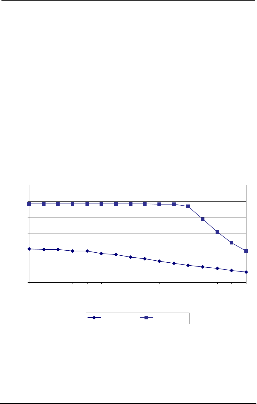
Figure 1 shows approximate RSSI performance. There are two versions of receivers used by the
AC5124. As of January of 2003 forward, only the New Revision receiver will be shipped. The RSSI pin
of the old revision requires the Host to provide a 27kΩ pull-down to ground. No pull-down should be
used with the new revision.
Figure
Figure Figure
Figure 1
11
1 - RSSI Voltage vs. Received Signal Strength
- RSSI Voltage vs. Received Signal Strength - RSSI Voltage vs. Received Signal Strength
- RSSI Voltage vs. Received Signal Strength
0
1
2
3
4
5
6
-20
-25
-30
-35
-40
-45
-50
-55
-60
-65
-70
-75
-80
-85
-90
-95
Input Power (dBm)
Voltage (V)
New Revision Old Revision

AC5124-10 Specifications
AC5124-10 SpecificationsAC5124-10 Specifications
AC5124-10 Specifications
11/24/03 15
3.2.2
3.2.23.2.2
3.2.2
In Range (IN_RANGE)
In Range (IN_RANGE)In Range (IN_RANGE)
In Range (IN_RANGE)
The IN_RANGE pin will be driven logic low when a Client is in range of a Server on the same Channel
and System ID. If a Client cannot hear a Server for the amount of time that is programmed in the
Range Refresh EEPROM address 32h, the Client drives the IN_RANGE pin logic high and enters a
search mode looking for a Server. As soon as it detects a Server, the IN_RANGE pin will be driven
logic low.
3.2.3
3.2.33.2.3
3.2.3
Baud Rate Selector (BDSEL)
Baud Rate Selector (BDSEL)Baud Rate Selector (BDSEL)
Baud Rate Selector (BDSEL)
The Baud Rate Selector (BDSEL) pin provides the OEM a default method of communicating with a
transceiver in the event the EEPROM baud rate parameters become corrupted. If Pin 26 is logic high
or not connected, the baud rate will default to that specified in EEPROM. If Pin 26 is logic low at
RESET, the baud rate will default to 9600 baud.
3.2.4
3.2.43.2.4
3.2.4
Microprocessor Reset (µP_RESET)
Microprocessor Reset (µP_RESET) Microprocessor Reset (µP_RESET)
Microprocessor Reset (µP_RESET)
Microprocessor Reset (µP_RESET) is achieved by holding Pin 38 at logic high for a minimum of 2ms.
If µP_RESET is performed after power has been applied to a transceiver and is stable, the reset time
will be significantly less. At all other times, Pin 38 should be logic low. If Pin 38 is not connected, the
microprocessor will hold Pin 38 logic low.
3.2.5
3.2.53.2.5
3.2.5
EEPROM Write Enable (WR_ENA)
EEPROM Write Enable (WR_ENA)EEPROM Write Enable (WR_ENA)
EEPROM Write Enable (WR_ENA)
EEPROM Write Enable (WR_ENA) is enabled when Pin 37 is logic low. Pin 37 must be logic low to
write to the EEPROM. The OEM must ensure a transceiver is NOT write-enabled during initial power
up or during a hardware RESET. Failure to do so may result in corruption of important EEPROM data.

AC5124-10 Specifications
AC5124-10 SpecificationsAC5124-10 Specifications
AC5124-10 Specifications
11/24/03 16
3.3
3.33.3
3.3 E
EE
ELECTRICAL
LECTRICAL LECTRICAL
LECTRICAL S
SS
SPECIFICATIONS
PECIFICATIONSPECIFICATIONS
PECIFICATIONS
Table
Table Table
Table 2
22
2 - DC Input Voltage Characteristics
- DC Input Voltage Characteristics - DC Input Voltage Characteristics
- DC Input Voltage Characteristics
Pin
PinPin
Pin Type
TypeType
Type Name
NameName
Name High Min.
High Min.High Min.
High Min. High Max.
High Max.High Max.
High Max. Low Min.
Low Min.Low Min.
Low Min. Low Max.
Low Max.Low Max.
Low Max. Unit
UnitUnit
Unit
2 I PKTMODE 0.2Vcc + 0.9 Vcc + 0.5 -0.5 0.2Vcc - 0.1 V
16 I RXD 0.2Vcc + 0.9 Vcc + 0.5 -0.5 0.2Vcc - 0.1 V
17 I RI_IN 2 Vcc + 1 -0.5 0.8 V
22 I DCD_IN 2 Vcc + 1 -0.5 0.8 V
26 I BDSEL 0.2Vcc + 0.9 Vcc + 0.5 -0.5 0.2Vcc - 0.1 V
27 I RTS 0.2Vcc + 0.9 Vcc + 0.5 -0.5 0.2Vcc - 0.1 V
34 I DTR 2 Vcc + 1 -0.5 0.8 V
37 I WR_ENA 0.7Vcc Vcc + 1 -0.3 0.5 V
38 I µP_RESET 0.7Vcc Vcc + 0.5 -0.5 0.2Vcc - 0.1 V
Table
Table Table
Table 3
33
3 - DC Output Voltage Characteristics
- DC Output Voltage Characteristics - DC Output Voltage Characteristics
- DC Output Voltage Characteristics
Pin
PinPin
Pin Type
TypeType
Type Name
NameName
Name High Min.
High Min.High Min.
High Min. Low Max.
Low Max.Low Max.
Low Max. Unit
UnitUnit
Unit
11 O RSSI Analog Analog V
14 O TXD Vcc - 1.5 @ -60uA 0.45 @ 1.6mA V
15 O IN_RANGE 2.4 @ -4mA 0.45 @ 4mA V
19 O RI_OUT 2.4 @ -4mA 0.45 @ 4mA V
23 O CTS Vcc - 1.5 @ -60uA 0.45 @ 1.6mA V
32 O DSR 2.4 @ -4mA 0.45 @ 4mA V
36 O DCD_OUT 2.4 @ -4mA 0.45 @ 4mA V

AC5124-10 Specifications
AC5124-10 SpecificationsAC5124-10 Specifications
AC5124-10 Specifications
11/24/03 17
4.
4.4.
4. Serial Interface Modes
Serial Interface ModesSerial Interface Modes
Serial Interface Modes
The AC5124 provides four Serial Interface Modes for interfacing to the Host, each having protocol
parameters that can be programmed for maximum system optimization. Serial Interface Modes 01, 02,
and 04 are referred to as Transparent Modes, indicating Host protocol is unnecessary for operation in
these modes – much like a serial cable. In addition, the transceiver-to-transceiver protocol for the
Transparent Modes is identical, allowing all three modes to coexist in the same network. Serial
Interface Mode 03, referred to as API Mode, is not interoperable with the Transparent Modes.
4.1
4.14.1
4.1 S
SS
SERIAL
ERIAL ERIAL
ERIAL I
IIINTERFACE
NTERFACE NTERFACE
NTERFACE M
MM
MODE
ODE ODE
ODE 01 – T
01 – T01 – T
01 – TRANSPARENT
RANSPARENTRANSPARENT
RANSPARENT, F
, F, F
, FIXED
IXED IXED
IXED P
PP
PACKET
ACKET ACKET
ACKET L
LL
LENGTH
ENGTHENGTH
ENGTH,
, ,
, WITH
WITH WITH
WITH T
TT
TIMEOUT
IMEOUTIMEOUT
IMEOUT
Transparent Mode 01 is the most popular interface mode because it can be used for many serial cable
replacement applications that meet any or all of the following conditions:
1) The Host always sends data packets that are the same size, allowing a transceiver to
take advantage of the fixed packet length option.
2) The Host sends variable-sized data packets, all of which are equal to or smaller than the
Fixed Packet Length. A transceiver will wait until the Interface Timeout expires or until the
Fixed Packet Length size is reached. Therefore, if multiple packets and/or portions of
packets are sent before the Interface Timeout expires, the receiving transceiver Host
must be able to process the multiple packets and/or portions of packets.
Packets will be transmitted over the RF interface when one of the following conditions occurs:
1) The number of data bytes received over the serial interface is equal to the Fixed Packet
Length specified by the OEM at EEPROM addresses 43h and 44h (43h is the MSB). The
maximum packet size is 07FFh or 2KB.
2) A byte gap larger than the Interface Timeout specified by the OEM at EEPROM address
4Dh occurs. This can be set to 00h, 40h, 80h, or C0h designating 4ms, 40ms, 300ms,
and 2.6s timeouts, respectively.
Any packets larger than the Fixed Packet Length will be parsed and sent consecutively by a
transceiver. For example, if the Fixed Packet Length is 128 bytes and the Host sends 150 bytes,
a transceiver will send 128 bytes and then 22 bytes after the timeout expires, consecutively.
4.2
4.24.2
4.2 S
SS
SERIAL
ERIAL ERIAL
ERIAL I
IIINTERFACE
NTERFACE NTERFACE
NTERFACE M
MM
MODE
ODE ODE
ODE 02 – T
02 – T02 – T
02 – TRANSPARENT
RANSPARENTRANSPARENT
RANSPARENT, E
, E, E
, END
ND ND
ND C
CC
CHARACTER
HARACTERHARACTER
HARACTER
Transparent Mode 02 is useful for applications where a particular character (such as a carriage return –
0Dh) is used to signify the end of each packet. The End Character is specified by the OEM at
EEPROM address 3Eh and can be set from 00h to FFh. Packets will be transmitted over the RF
interface when the OEM-defined End Character is received by a transceiver. The maximum packet
size is 07FFh or 2KB, including the End Character. Note that the End Character will be transmitted to
the Host.

AC5124-10 Specifications
AC5124-10 SpecificationsAC5124-10 Specifications
AC5124-10 Specifications
11/24/03 18
4.3
4.34.3
4.3 S
SS
SERIAL
ERIAL ERIAL
ERIAL I
IIINTERFACE
NTERFACE NTERFACE
NTERFACE M
MM
MODE
ODE ODE
ODE 03 – API
03 – API03 – API
03 – API
API Mode is the most complex and detailed mode, where most of the control is given to the Host. This
mode may seem extensive at first glance; however, it follows a specific pattern of commands and
responses similar to an Ethernet protocol. The commands are grouped into two categories, System
Commands and Transceiver Commands. See Section 5, API Command Set
Section 5, API Command SetSection 5, API Command Set
Section 5, API Command Set for the full list of
commands and definitions.
4.4
4.44.4
4.4 S
SS
SERIAL
ERIAL ERIAL
ERIAL I
IIINTERFACE
NTERFACE NTERFACE
NTERFACE M
MM
MODE
ODE ODE
ODE 04 – T
04 – T04 – T
04 – TRANSPARENT
RANSPARENTRANSPARENT
RANSPARENT, F
, F, F
, FIXED
IXED IXED
IXED P
PP
PACKET
ACKET ACKET
ACKET L
LL
LENGTH
ENGTHENGTH
ENGTH, N
, N, N
, NO
O O
O T
TT
TIMEOUT
IMEOUTIMEOUT
IMEOUT
In Transparent Mode 04, packets will be transmitted over the RF interface when the number of data
bytes received over the serial interface is equal to the Fixed Packet Length specified by the OEM at
EEPROM addresses 43h and 44h (43h is the MSB). The maximum packet size is 07FFh or 2KB. This
mode of operation is recommended for applications that meet any of the following conditions:
1) The Host always sends data packets that are the same size.
2) The Host sends variable-sized data packets, all of which are equal to or smaller than the
Fixed Packet Length. A transceiver will wait indefinitely until the Fixed Packet Length size
is reached. Therefore, multiple packets and/or portions of packets will be sent,
depending on the timing and size of the packets. As a result, the receiving transceiver
Host must be able to process the multiple packets and/or portions of packets.
4.5
4.54.5
4.5 S
SS
SERIAL
ERIAL ERIAL
ERIAL I
IIINTERFACE
NTERFACE NTERFACE
NTERFACE B
BB
BUFFER
UFFERUFFER
UFFER
The serial interface buffer provides 8 KBytes of memory segmented into four dynamic regions. In API
Mode, only one region is utilized. In all Transparent Modes, a buffer region is used each time a packet
release condition is met. As an example, in Transparent Mode 02, if 500 Bytes are transmitted,
including the specified End Character, 500 Bytes will be stored in the first region and the remaining 7.5
KBytes will be dynamically allocated for the next three packets. It is strongly recommended that CTS
or upper layer protocol with acknowledgements be used by the OEM when operating in any of the
Transparent Modes to prevent lost data. Otherwise, if all four buffers are filled and the Host continues to
send data over the serial interface, the data will be discarded by the transceiver. This condition can be
eliminated by using CTS.
4.6
4.64.6
4.6 A
AA
ADDRESSED
DDRESSED DDRESSED
DDRESSED & B
& B& B
& BROADCAST
ROADCAST ROADCAST
ROADCAST C
CC
COMMUNICATION
OMMUNICATIONOMMUNICATION
OMMUNICATION
The AC5124 supports both Addressed and Broadcast Modes of communication in all Serial Interface
Modes. As necessary, refer to Section 5, API Command Set
Section 5, API Command SetSection 5, API Command Set
Section 5, API Command Set for API command definitions
and Section
SectionSection
Section
6, Configuring the AC5124
6, Configuring the AC51246, Configuring the AC5124
6, Configuring the AC5124 for EEPROM address definitions.

AC5124-10 Specifications
AC5124-10 SpecificationsAC5124-10 Specifications
AC5124-10 Specifications
11/24/03 19
4.6.1
4.6.14.6.1
4.6.1
Addressed Mode
Addressed ModeAddressed Mode
Addressed Mode
4.6.1.1
4.6.1.14.6.1.1
4.6.1.1 Transparent Mode Operation
Transparent Mode OperationTransparent Mode Operation
Transparent Mode Operation
Addressed communication in a Transparent Mode is achieved by programming the Transmit Mode
byte, located at EEPROM address 4Bh, to a value of 00h. In addition, the 6-byte IEEE destination
address must be programmed in the respective transceivers starting at EEPROM address 50h (i.e. the
Server IEEE address must be programmed in the Client and the Client IEEE address must be
programmed in the Server). Auto Destination could also be enabled in the Client transceiver as
described in Section 4.6.1.2, Auto Destination
Section 4.6.1.2, Auto DestinationSection 4.6.1.2, Auto Destination
Section 4.6.1.2, Auto Destination.
In this configuration, a packet is sent to the destination transceiver until a positive acknowledgement is
received or until all Transmit Attempts have completed. The number of Transmit Attempts is specified
at EEPROM address 2Fh and can be programmed with values ranging from 01h to FFh. If a packet is
not received successfully after all attempts have been made, the packet transmission will be aborted.
The RF acknowledgements in all Transparent Modes are not sent to the Hosts; therefore, the Host is
responsible for detecting a non-deliverable packet, if necessary. Addressed Mode is recommended
for all point-to-point (one Server and on Client) applications because a transceiver only sends the
packet as many times as necessary. For example, if a transceiver receives a positive
acknowledgement before all attempts are made, it will ignore the remaining attempts and start sending
the next packet.
4.6.1.2
4.6.1.24.6.1.2
4.6.1.2 Auto Destination
Auto DestinationAuto Destination
Auto Destination
The AC5124 also supports an addressed mode of communication called Auto Destination. Auto
Destination is only for Clients operating in one of the Transparent Modes. To configure a Client for
Auto Destination, set bit 7 of EEPROM address 4Fh to a value of 1. With Auto Destination enabled, a
Client has the ability to detect any Server with the same Channel and System ID. Hence, a Client’s
Destination IEEE MAC Address, located at EEPROM address 50h, is not required to be programmed
with the Server’s IEEE address.
Auto Destination allows a Client to dynamically route all communications to the Server that is in range,
making it useful for mobile or roaming applications where a Client will be interfacing with different
Servers from time to time. It is important to note that multiple Servers with the same Channel and
System ID must not be located in range of one another. Doing so will cause inoperability of the
system.
4.6.1.3
4.6.1.34.6.1.3
4.6.1.3 API Mode Operation
API Mode OperationAPI Mode Operation
API Mode Operation
In API Mode, the IEEE Source and Destination Address must be included in the data frame of the
Send
SendSend
Send
Data
Data Data
Data
command. The Host is responsible for constructing the packet before sending it to the
transceiver. Like a transceiver operating in a Transparent Mode, a packet will be sent until a successful
Send Data Complete
Send Data CompleteSend Data Complete
Send Data Complete
command is sent to the Host or all Transmit Attempts are completed. If the
packet is not received successfully after all attempts have been made, the Host will be notified by the
Send Data Complete
Send Data CompleteSend Data Complete
Send Data Complete
command with a failure code of 1. Thus, the acknowledgements in API Mode are
sent to the Hosts and can be used to guarantee packet delivery.

AC5124-10 Specifications
AC5124-10 SpecificationsAC5124-10 Specifications
AC5124-10 Specifications
11/24/03 20
4.6.2
4.6.24.6.2
4.6.2
Broadcast Mode
Broadcast ModeBroadcast Mode
Broadcast Mode
4.6.2.1
4.6.2.14.6.2.1
4.6.2.1 Transparent Mode Operation
Transparent Mode OperationTransparent Mode Operation
Transparent Mode Operation
Broadcast communication in a Transparent Mode is intended for use in a point-to-multipoint network
(one Server and many Clients). In this configuration, the Server must be programmed for Broadcast
Mode by programming the Transmit Mode byte, located at EEPROM address 4Bh, to a value of 01h. It
is recommended that all Clients be programmed in Addressed Mode or Auto Destination Mode to
provide more reliable delivery of data to the Server, resulting in more efficient network communications.
Unlike the Transmit Attempts process in Addressed Mode, a packet will be transmitted until all
Broadcast Attempts are completed. The number of Broadcast Attempts is specified at EEPROM
address 4Eh and can be programmed with values ranging from 01h to FFh. If a transceiver receives a
packet multiple times without error, only the first error-free packet will be sent to the Host. All others will
be discarded. The OEM should carefully determine the number of Broadcast Attempts by performing
extensive testing in their application. If a packet is sent more times than necessary, network
performance can degrade.
4.6.2.2
4.6.2.24.6.2.2
4.6.2.2 API Mode Operation
API Mode OperationAPI Mode Operation
API Mode Operation
Sending a broadcast packet is accomplished by constructing the data frame of the
Send Data
Send DataSend Data
Send Data
command with all six bytes of the IEEE Destination Address set to a value of FFh.
Unlike the Transmit Attempts process in Addressed Mode, a packet will be transmitted until all
Broadcast Attempts are completed, after which, a successful
Send Data Complete
Send Data CompleteSend Data Complete
Send Data Complete
command will be
sent to the Host. The number of Broadcast Attempts is specified at EEPROM address 4Eh and can be
programmed with values ranging from 01h to FFh. If a transceiver receives a packet multiple times
without error, only the first error-free packet will be sent to the Host. All others will be discarded. The
OEM should carefully determine the number of Broadcast Attempts by performing extensive testing in
their application. If a packet is sent more times than necessary, network performance can degrade.
4.7
4.74.7
4.7 H
HH
HANDSHAKING
ANDSHAKINGANDSHAKING
ANDSHAKING
Though handshaking is not required for transceiver operation, it is recommended to achieve optimum
system performance. Most applications benefit from using Clear To Send (CTS) only, while others
may also need Request To Send (RTS). In addition, some applications may require full modem
handshaking.
4.7.1
4.7.14.7.1
4.7.1
CTS Handshaking
CTS HandshakingCTS Handshaking
CTS Handshaking
CTS is used by the transceiver to keep the Host from transmitting data to it. If the Host sends the
transceiver data when CTS is logic high (inactive), the data will be lost. Normally, CTS will go logic
high for a minimum of 40µs following the transmission of a data packet from the Host to the
transceiver. However, if the serial interface buffers on a transceiver become full and the transceiver
cannot transmit the data, the transceiver will hold CTS logic high until it can free a buffer. For example,
this can occur when a transceiver goes out of range. Therefore, it is strongly recommended that the
Host use CTS. All serial data must be transmitted LSB first.

AC5124-10 Specifications
AC5124-10 SpecificationsAC5124-10 Specifications
AC5124-10 Specifications
11/24/03 21
4.7.2
4.7.24.7.2
4.7.2
RTS Handshaking
RTS HandshakingRTS Handshaking
RTS Handshaking
When the RTS bit is enabled by setting bit 3 of the Serial Interface Mode byte at EEPROM address 4Ah
to a value of 1, Pin 27 is used by the Host to keep a transceiver from transmitting data to it. When RTS
is logic high (inactive), a transceiver cannot send data to the Host. Holding RTS logic high for too long
can congest RF communications. For example, if RTS is held logic high while a transceiver continues
to receive data, eventually the receive buffer will fill. If this occurs, a transceiver will not be able to send
or receive any data until it can free the buffer.
4.7.3
4.7.34.7.3
4.7.3
Modem Handshaking
Modem HandshakingModem Handshaking
Modem Handshaking
In Modem Mode, a transceiver uses all standard RS232 (TTL level) handshaking lines to negotiate
communications. These lines include TXD, RXD, CTS, RTS, DTR, DSR, DCD_IN, DCD_OUT, RI_IN and
RI_OUT.
To enable Modem Mode, set bit 6 and bit 3 of EEPROM address 4Ah to a value of 1. Bit 6 will enable
all modem lines except RTS. As mentioned in Section 4.7.2, RTS Handshaking
Section 4.7.2, RTS HandshakingSection 4.7.2, RTS Handshaking
Section 4.7.2, RTS Handshaking, setting bit 3 to a value
of 1 enables RTS. Modem Mode is overkill for most applications and is intended mainly for wireless
modem applications.
4.7.3.1
4.7.3.14.7.3.1
4.7.3.1 Radio Connected to DTE
Radio Connected to DTERadio Connected to DTE
Radio Connected to DTE
When a transceiver is connected to a Data Terminal Equipment (DTE) device, like a PC, and full
modem support is desired, a transceiver will use the following configuration in most applications:
DTE (PC)
DTE (PC)DTE (PC)
DTE (PC) TXD RXD CTS RTS DTR DSR DCD RI
Transceiver
TransceiverTransceiver
Transceiver RXD
(16)
TXD
(14)
CTS
(23)
RTS
(27)
DTR
(34)
DSR
(32)
DCD_OUT
(36)
RI_OUT
(19)
4.7.3.2
4.7.3.24.7.3.2
4.7.3.2 Radio Connected to DCE
Radio Connected to DCERadio Connected to DCE
Radio Connected to DCE
When a transceiver is connected to a Data Communication Equipment (DCE) device, like a modem,
and full modem support is desired, a transceiver will use the following configuration in most
applications:
DCE (Modem)
DCE (Modem)DCE (Modem)
DCE (Modem) TXD RXD CTS RTS DTR DSR DCD RI
Transceiver
TransceiverTransceiver
Transceiver RXD
(16)
TXD
(14)
RTS
(27)
CTS
(23)
DSR
(32)
DTR
(34)
DCD_IN
(22)
RI_IN
(17)

AC5124-10 Specifications
AC5124-10 SpecificationsAC5124-10 Specifications
AC5124-10 Specifications
11/24/03 22
5.
5.5.
5. API Command Set
API Command SetAPI Command Set
API Command Set
In API Mode, the Host and transceiver utilize a set of commands to program the EEPROM parameters
defined in Section 6, Configuring the AC5124
Section 6, Configuring the AC5124Section 6, Configuring the AC5124
Section 6, Configuring the AC5124, as well as control and monitor network communications.
As mentioned in Section 4.3, Serial Interface Mode 03 – API
Section 4.3, Serial Interface Mode 03 – APISection 4.3, Serial Interface Mode 03 – API
Section 4.3, Serial Interface Mode 03 – API, the commands are grouped into two
categories, System Commands and Transceiver Commands. Each group of commands are listed and
defined in this section. It is important to note these commands can only be used when a transceiver is
operating in the API Mode, which is accomplished by programming bits 0 and 1 of EEPROM address
4Ah to a value of 1. The command format is defined as follows:
Command Length Data Checksum
Command
CommandCommand
Command (1 Byte) – Hex command as shown in Table 4 – System Command Set
Table 4 – System Command SetTable 4 – System Command Set
Table 4 – System Command Set and Table
TableTable
Table
5 – Transceiver Command Set
5 – Transceiver Command Set5 – Transceiver Command Set
5 – Transceiver Command Set.
Length
LengthLength
Length (2 Bytes) – This is the total size of the remaining data for this command. The length
field is in little endian format (i.e. low byte/high byte). This length does not include the
checksum.
Data
DataData
Data (N Bytes) – The actual data associated with the command or sub-command.
Checksum
ChecksumChecksum
Checksum (1 Byte) – The checksum is a byte-by-byte, bitwise “EXCLUSIVE OR” of the
Command, Length and Data block.
Here are some important facts to remember when operating in API Mode:
Here are some important facts to remember when operating in API Mode:Here are some important facts to remember when operating in API Mode:
Here are some important facts to remember when operating in API Mode:
1) All commands issued by the Host must receive an
Acknowledge
AcknowledgeAcknowledge
Acknowledge
command from the
transceiver to signal completion of the issued command. This serves as flow control for
the information going to the transceiver.
2) When a command is issued by the transceiver to the Host, the Host must be ready to
accept the command and any data following the command. The transceiver will not get
an
Acknowledge
AcknowledgeAcknowledge
Acknowledge
command from the Host.
3) Although the Host will receive an
Acknowledge
AcknowledgeAcknowledge
Acknowledge
command for every command sent to the
transceiver, the Host must be able to accept any command issued by the transceiver
prior to receiving the
Acknowledge
AcknowledgeAcknowledge
Acknowledge
command.

AC5124-10 Specifications
AC5124-10 SpecificationsAC5124-10 Specifications
AC5124-10 Specifications
11/24/03 23
5.1
5.15.1
5.1 S
SS
SYSTEM
YSTEM YSTEM
YSTEM C
CC
COMMAND
OMMAND OMMAND
OMMAND S
SS
SET
ETET
ET
The System Commands allow the OEM to initialize the system and perform general system analysis.
In addition, the EEPROM parameters can only be programmed using these commands. The table
below summarizes the commands.
Table
Table Table
Table 4
44
4 - System Command Set
- System Command Set - System Command Set
- System Command Set
Name
NameName
Name Command
CommandCommand
Command Length
LengthLength
Length
Low
LowLow
Low
Length
LengthLength
Length
High
HighHigh
High
Data
DataData
Data Checksum
ChecksumChecksum
Checksum
Reset AAh 00h 00h No Data AAh
Control 86h 1 to 5 (depends on
sub-command)
As Required As Required
Diagnostic Result 87h As Required As Required As Required
Standby 88h 01h 00h 00h – Client Sleep Walk
01h – Server Deep Sleep
04h – Cancel Standby
As Required
Status Request 8Ah 01h 00h 0 – Reset error counter
1 – Don’t do anything
8Ah
Status Reply 8Bh 14h - 74h 00h See Section 5.1.6, Status
Section 5.1.6, StatusSection 5.1.6, Status
Section 5.1.6, Status
Reply
ReplyReply
Reply
As Required
Update EEPROM
Checksum
8Ch 00h 00h No Data 8Ch
Check EEPROM
Checksum
8Dh 00h 00h No Data 8Dh
EEPROM Checksum
Status
8Eh 01h 00h 0 – Checksum invalid
1 – Checksum valid
8Eh
Acknowledge As Required As Required As Required As Required
5.1.1
5.1.15.1.1
5.1.1
Reset
ResetReset
Reset
The Host issues this command to a transceiver. This command provides a software reset to a
transceiver, initializing the code at the same location as a hardware reset. The Host must wait for the
Acknowledge
AcknowledgeAcknowledge
Acknowledge
command before issuing any additional commands. This command must be followed
by an
RF Enable
RF EnableRF Enable
RF Enable
command.
Example: AA|00|00|AA (There are no Data bytes for this command)
Acknowledge: AA|01|00|00|AB

AC5124-10 Specifications
AC5124-10 SpecificationsAC5124-10 Specifications
AC5124-10 Specifications
11/24/03 24
5.1.2
5.1.25.1.2
5.1.2
Control
ControlControl
Control
The Host issues this command to a transceiver to write and read EEPROM addresses as well as for
NOP. The Host must wait for the
Diagnostic Result
Diagnostic ResultDiagnostic Result
Diagnostic Result
command before issuing any additional
commands. Refer to Section 6, Configuring the AC5124
Section 6, Configuring the AC5124Section 6, Configuring the AC5124
Section 6, Configuring the AC5124 for the list of configurable EEPROM
parameters.
Sub-command (Counts as 1 Byte in the
Sub-command (Counts as 1 Byte in theSub-command (Counts as 1 Byte in the
Sub-command (Counts as 1 Byte in the
Length)
Length)Length)
Length)
Description
DescriptionDescription
Description
02h Read EEPROM. Additional data: first 2 bytes specify
starting address. Second 2 bytes specify ending
address.
08h NOP.
09h Write EEPROM. Additional data: first 2 Bytes specify
starting address. Second 2 Bytes specify ending
address. Remaining bytes specify data to be written.
(Range 00h to 7Fh)
Data Frame:
86h Length Low 00h Sub-command Data Checksum
Read EEPROM Example (Addresses 04h to 09h): 86|05|00|02|04|00|09|00|8C
Diagnostic Result: 87|07|00|02|FF|FF|FF|FF|FF|FF|82
Example (NOP): 86|01|00|08|8F
Diagnostic Result: 87|02|00|08|00|8D
Write EEPROM Example (write value 01h to address 31h): 86|06|00|09|31|00|31|00|01|88
Diagnostic Result: 87|02|00|09|00|8C
Any additional sub-commands are reserved by the system and if used may cause system operation
problems.
5.1.3
5.1.35.1.3
5.1.3
Diagnostic Result
Diagnostic ResultDiagnostic Result
Diagnostic Result
A transceiver issues this command to the Host in response to a
Control
ControlControl
Control
command.
Sub result (Counts as 1 Byte in the Length)
Sub result (Counts as 1 Byte in the Length)Sub result (Counts as 1 Byte in the Length)
Sub result (Counts as 1 Byte in the Length) Description
DescriptionDescription
Description
02h Read EEPROM
08h NOP. Returns 6 Bytes (87 02 00 08 00 8D)
09h Write EEPROM status.
0 - Write successful. 1- Write failed.
Data Frame:
87h Length Low Length High Sub-result Data Checksum

AC5124-10 Specifications
AC5124-10 SpecificationsAC5124-10 Specifications
AC5124-10 Specifications
11/24/03 25
5.1.4
5.1.45.1.4
5.1.4
Standby
StandbyStandby
Standby
The Host issues the following commands to enable Sleep Walk Mode for Clients and Deep Sleep
Mode for Servers. See Section 6.1.13.3, Power Down Modes
Section 6.1.13.3, Power Down ModesSection 6.1.13.3, Power Down Modes
Section 6.1.13.3, Power Down Modes for detailed information on these modes.
• 88 01 00 00 89 – This will command the Client into Sleep Walk mode.
• 88 01 00 01 88 – This will command the Server into Deep Sleep mode.
• 88 01 00 04 8D – This will cancel the power down functions.
5.1.5
5.1.55.1.5
5.1.5
Status Request
Status RequestStatus Request
Status Request
The Host issues this command to a transceiver to determine various statistics associated with the RF
Data Link Layer. A Data value of 00h will reset the Error Counters while a value of 01h will leave them
at their current values. The Host must wait for the
Status Reply
Status ReplyStatus Reply
Status Reply
command before issuing any additional
commands.
Example: 8A|01|00|01|8A
Status Reply (0 Active Transceivers): 8B|20|00|A8|03|00|00|00|00|00|01|00|00|00|00|00|00|00|
00|00|00|00|01|00|50|67|00|3C|3D|D3|01|00|07|00|00|E3
5.1.6
5.1.65.1.6
5.1.6
Status Reply
Status ReplyStatus Reply
Status Reply
A transceiver issues this command to the Host in response to a
Status Request
Status RequestStatus Request
Status Request
command. The
parameters pertain to the RF Data Link Layer and provide cumulative totals. The statistics and their
sizes are shown below:
Name
NameName
Name Type
TypeType
Type Description
DescriptionDescription
Description Size
SizeSize
Size
Transceiver Time Time
Counter
Incremented by 1 every 250ms. Initialized
to 0 at power on or reset.
Unsigned Byte –
3 Bytes, Low
Byte first
Tx Failures Error
Counter
Number of times a transceiver was not able
to deliver a data frame to the destination
Unsigned Long -
4 Bytes
Tx Retries Error
Counter
Number of times a transceiver had to retry
before delivering a data frame to the
destination
Unsigned Long -
4 Bytes
Rx Failures Error
Counter
Number of times a transceiver had to throw
away a received data frame because of bad
CRC/checksum
Unsigned Long -
4 Bytes
Rx Retries Error
Counter
Number of times data frames had to be
retransmitted before a valid data frame was
received
Unsigned Long -
4 Bytes
Num Active
Transceivers
Data
Counter
Number of Clients registered to a
Server. If the Transceiver under
consideration is a Client, just return 0
Unsigned Byte -
1 Byte
List of Registered
Transceivers
Identity List of 6-Byte IEEE 802.3 transceiver
addresses + 3 Byte time stamp + 3 Byte
packet count. Time stamp and packet
counter are reset at power on or Reset.
12 Bytes * Num
Reg Clients

AC5124-10 Specifications
AC5124-10 SpecificationsAC5124-10 Specifications
AC5124-10 Specifications
11/24/03 26
Status Reply Example
Status Reply ExampleStatus Reply Example
Status Reply Example
Name
NameName
Name Type
TypeType
Type 0 Active Transceivers
0 Active Transceivers0 Active Transceivers
0 Active Transceivers 2 Active Transceivers
2 Active Transceivers2 Active Transceivers
2 Active Transceivers
Transceiver Time Time Counter 1 Byte – TL
1 Byte – TM
1 Byte – TH
1 Byte – TL
1 Byte – TM
1 Byte – TH
Tx Failures Error Counter 4 Bytes 4 Bytes
Tx Retries Error Counter 4 Bytes 4 Bytes
Rx Failures Error Counter 4 Bytes 4 Bytes
Rx Retries Error Counter 4 Bytes 4 Bytes
Num Active Transceivers Data Counter 0 2
List of Registered
Transceivers
Identity 6 Bytes IEEE Address
3 Bytes time stamp
3 Bytes packet count
6 Bytes IEEE Address
3 Bytes time stamp
3 Bytes packet count
Checksum Actual Actual
Data Frame:
8Bh Length Low 00h Data Checksum
5.1.7
5.1.75.1.7
5.1.7
Update EEPROM Checksum
Update EEPROM ChecksumUpdate EEPROM Checksum
Update EEPROM Checksum
The Host issues this command to a transceiver to recalculate the checksum. The Host typically issues
this command after it has completed writing data to the EEPROM. The Host must wait for the
Acknowledge
AcknowledgeAcknowledge
Acknowledge
command before issuing any additional commands.
Example: 8C|00|00|8C (There are no Data bytes for this command)
Acknowledge: 8C|00|00|8C
5.1.8
5.1.85.1.8
5.1.8
Check EEPROM Checksum
Check EEPROM ChecksumCheck EEPROM Checksum
Check EEPROM Checksum
The Host issues this command to a transceiver to validate the EEPROM checksum. The Host typically
issues this command after resetting a transceiver. A transceiver replies with a valid or invalid
checksum by sending back the
EEPROM Checksum Status
EEPROM Checksum StatusEEPROM Checksum Status
EEPROM Checksum Status
command.
Example: 8D|00|00|8D (There are no Data bytes for this command)
EEPROM Checksum Status: 8E|01|00|01|8E
5.1.9
5.1.95.1.9
5.1.9
EEPROM Checksum Status
EEPROM Checksum StatusEEPROM Checksum Status
EEPROM Checksum Status
A transceiver issues this command to the Host in response to a
Check EEPROM Checksum
Check EEPROM ChecksumCheck EEPROM Checksum
Check EEPROM Checksum
command. A Data value of 00h indicates an invalid Checksum while a value of 01h indicates a valid
Checksum.

AC5124-10 Specifications
AC5124-10 SpecificationsAC5124-10 Specifications
AC5124-10 Specifications
11/24/03 27
5.1.10
5.1.105.1.10
5.1.10
Acknowledge
AcknowledgeAcknowledge
Acknowledge
A transceiver issues this command in response to some of the Host commands indicating a positive
response. The
Acknowledge
AcknowledgeAcknowledge
Acknowledge
consists of the Host command sequence with a zero length, unless
otherwise noted.
5.2
5.25.2
5.2 T
TT
TRANSCEIVER
RANSCEIVER RANSCEIVER
RANSCEIVER C
CC
COMMAND
OMMAND OMMAND
OMMAND S
SS
SET
ETET
ET
The Transceiver Commands allow the OEM to control the flow of data into and out of a transceiver as
well as initialization of a transceiver. The table below summarizes the commands.
Table
Table Table
Table 5
55
5 - Transceiver Command Set
- Transceiver Command Set - Transceiver Command Set
- Transceiver Command Set
Name
NameName
Name Command
CommandCommand
Command Length
LengthLength
Length
Low
LowLow
Low
Length
LengthLength
Length
High
HighHigh
High
Data
DataData
Data Checksum
ChecksumChecksum
Checksum
RF Enable 80h 00h 00h No Data 80h
Send Data 81h 0Ch – 7FBh (includes
802.3 Header)
As Required As Required
Send Data Complete 82h 01h 00h 00h or 01h (See
Section 5.2.3, Send
Section 5.2.3, SendSection 5.2.3, Send
Section 5.2.3, Send
Data Complete
Data CompleteData Complete
Data Complete)
As Required
Received Data 83h 0Ch – 7FBh (includes
802.3 Header)
As Required As Required
In Range 84h 06h 00h IEEE 802.3 address of
Server
As Required
Out of Range 85h 00h 00h No Data 85h
5.2.1
5.2.15.2.1
5.2.1
RF Enable
RF EnableRF Enable
RF Enable
The Host issues this command to a transceiver prior to any RF data transfers. The Host typically issues
this command after resetting a transceiver. This enables the RF interface of a transceiver and turns the
transmitter/receiver ON. The Host must wait for the
Acknowledge
AcknowledgeAcknowledge
Acknowledge
command before issuing any
additional commands. Ensure that only one RF Enable command is issued following a Reset.
Example: 80|00|00|80 (There are no Data bytes for this command)
Acknowledge: 80|00|00|80

AC5124-10 Specifications
AC5124-10 SpecificationsAC5124-10 Specifications
AC5124-10 Specifications
11/24/03 28
5.2.2
5.2.25.2.2
5.2.2
Send Data
Send DataSend Data
Send Data
The Host issues this command to a transceiver before sending a data packet to it. Broadcast frames
are sent to all registered Clients at the same time without RF-Layer acknowledgements. Broadcast
frames are not required to reach all destinations. The Host must wait for the
Send Data Complete
Send Data CompleteSend Data Complete
Send Data Complete
command before issuing any additional commands.
Data Frame:
81h Length Low Length High Data Checksum
Destination
DestinationDestination
Destination
Address
AddressAddress
Address
Source Address
Source AddressSource Address
Source Address Data
DataData
Data
MS Byte…LS Byte MS Byte…LS Byte
Note: The Data must include the following header information:
• (6) Bytes for the IEEE 802.3
destination
address, or FF FF FF FF FF FF for broadcast
packets
• (6) Bytes for the IEEE 802.3
source
address
These unique IEEE addresses are provided by AeroComm and stored in EEPROM addresses 28h –
2Dh.
5.2.3
5.2.35.2.3
5.2.3
Send Data Complete
Send Data CompleteSend Data Complete
Send Data Complete
A transceiver issues this command upon completion of the data transmission process, as indicated by
a RF-layer acknowledgment from the destination transceiver. An additional byte of data indicates a
success or a failure code. This command will be returned for every
Send Data
Send DataSend Data
Send Data
command unless the
device power fails.
• Command:
Command:Command:
Command: 82h
• Length:
Length:Length:
Length: 01h
• Data:
Data:Data:
Data: 00h – Indicates success. 01h – Can’t send packet.
• Checksum:
Checksum:Checksum:
Checksum: As required
Data Frame:
82h 01h 00h Data Checksum
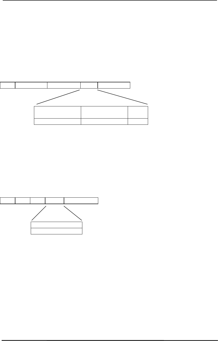
AC5124-10 Specifications
AC5124-10 SpecificationsAC5124-10 Specifications
AC5124-10 Specifications
11/24/03 29
5.2.4
5.2.45.2.4
5.2.4
Received Data
Received DataReceived Data
Received Data
A transceiver issues this command upon reception of data from the RF interface. The information in
the data frame is the received data.
Since more than one Client can transmit to a Server, multiple
Received Data
Received Data Received Data
Received Data
commands can be issued
to the Server Host at the same time. The command does not require an
Acknowledge
AcknowledgeAcknowledge
Acknowledge
command;
therefore, the Server Host must be capable of receiving multiple, consecutive
Received Data
Received DataReceived Data
Received Data
commands.
Data Frame:
83h Length Low Length High Data Checksum
Destination
DestinationDestination
Destination
Address
AddressAddress
Address
Source Address
Source AddressSource Address
Source Address Data
DataData
Data
MS Byte…LS Byte MS Byte…LS Byte
5.2.5
5.2.55.2.5
5.2.5
In Range
In RangeIn Range
In Range
The Client issues this command upon detecting a Server beacon after a Reset or after an
Out of Range
Out of RangeOut of Range
Out of Range
command has been issued to the Host. The Client Host will get updated with this command at the
time intervals specified by the Range Refresh parameter at EEPROM address 32h. The OEM should
allow for some hysterisis so the Host isn’t flooded with these commands in a fringe coverage area.
AeroComm has established a default value of 5 seconds through extensive testing. This command
includes the IEEE 802.3 Server Address.
Data Frame:
84h 06h 00h Data Checksum
Server IEEE Address
Server IEEE AddressServer IEEE Address
Server IEEE Address
MS Byte…LS Byte
5.2.6
5.2.65.2.6
5.2.6
Out of Range
Out of RangeOut of Range
Out of Range
The Client issues this command if it does not detect a Server beacon after a Reset or after an
In Range
In RangeIn Range
In Range
command has been issued to the Host. The Client Host will get updated with these commands at the
time intervals specified by the Range Refresh parameter at EEPROM address 32h. The OEM should
allow for some hysterisis so the Host isn’t flooded with these commands in a fringe coverage area.
AeroComm has established a default value of 5 seconds through extensive testing.

AC5124-10 Specifications
AC5124-10 SpecificationsAC5124-10 Specifications
AC5124-10 Specifications
11/24/03 30
6.
6.6.
6. AT Command Set
AT Command SetAT Command Set
AT Command Set
Versions 3.5 and higher of the AC5124 family firmware implement an AT Command set, which is used
for modifying settings during runtime without having to use any hardware control lines. AT Commands
are valid for modes 1, 2, and 4 of the AC5124. Whether in mode 1, 2, or 4, this command must be sent
to the radio as a complete packet. Any characters before or after this command that become
appended to this string to form a larger packet will cause the packet to be interpreted as a packet to
send over the RF and not an AT command. If the AT command set is used in mode 2, the end
character must be 0DH (13 decimal). If the AT command set is used in mode 4, the fixed length must
be set to 6. If power is lost while in AT command mode, the radio will power back up into normal
mode. All AT command characters should be capitalized. All AT commands end in a 0DH character
(13 decimal). The radio will not respond to an AT command unless the 0DH character is detected at
the end of the command.
6.1
6.16.1
6.1 IRAM D
IRAM DIRAM D
IRAM DEFINED
EFINEDEFINED
EFINED
IRAM is an acronym for Internal Random Access Memory. IRAM is a static memory that holds many of
the parameters that control the radio such as channel number. Using the Read/Write IRAM command
allows these parameters to be changed dynamically. Because IRAM is static, when the radio is reset,
these parameters will revert back to the settings stored in the E²PROM. Be careful not to change
undocumented IRAM addresses as undesired operation may occur. Below is a list of IRAM
parameters that can be changed in the radio:
IRAM Address (Hex) Description
F5 Channel Number
6.2
6.26.2
6.2 C
CC
COMMAND
OMMAND OMMAND
OMMAND I
IIINSTRUCTIONS
NSTRUCTIONSNSTRUCTIONS
NSTRUCTIONS/R
/R/R
/RESPONSES
ESPONSESESPONSES
ESPONSES
Below is a description of the AT Commands and their appropriate responses.

AC5124-10 Specifications
AC5124-10 SpecificationsAC5124-10 Specifications
AC5124-10 Specifications
11/24/03 31
6.2.1
6.2.16.2.1
6.2.1
Enter Command Mode
Enter Command ModeEnter Command Mode
Enter Command Mode
Prior to sending any other AT command, the radio must be sent the Enter Command Mode command
by the OEM Host. Below is a description of that command:
AT+++↵
Where ↵ is equal to 0DH (13 decimal).
If it is unable to successfully receive the command, the radio will interpret the string as a packet to send
out over the RF and will act accordingly. Upon successfully receiving the Enter Command Mode
command, the radio will be ready to receive other AT commands and will issue the following response
to the OEM Host:
OK↵
Where ↵ is equal to 0DH (13 decimal).
After successfully receiving the Enter Command Mode command, the radio will not be able to
communicate with other radios until AT command mode is exited. If a server is commanded into AT
mode, the clients will go out of range.
6.2.2
6.2.26.2.2
6.2.2
Exit Command Mode
Exit Command ModeExit Command Mode
Exit Command Mode
To exit AT mode without resetting the internal static parameters of the radio, an Exit Command Mode
command should be sent to the radio by the OEM Host. Below is a description of that command:
ATO↵
Where ↵ is equal to 0DH (13 decimal).
If it successfully receives the command, the radio will issue the following response to the OEM Host:
OK↵
Where ↵ is equal to 0DH (13 decimal).
If it is at least able to receive the ↵ character but there is an error in the command or part of the
command is missing, the radio will issue the following response to the OEM Host:
ERROR↵
Where ↵ is equal to 0DH (13 decimal).
Upon successfully receiving the Exit Command Mode command, the radio will resume RF
communications.

AC5124-10 Specifications
AC5124-10 SpecificationsAC5124-10 Specifications
AC5124-10 Specifications
11/24/03 32
6.2.3
6.2.36.2.3
6.2.3
Power-on Reset Command
Power-on Reset CommandPower-on Reset Command
Power-on Reset Command
To force the radio to perform a Power-on Reset, the Power-on Reset command should be sent to the
radio by the OEM Host. Below is a description of that command:
ATZ↵
Where ↵ is equal to 0DH (13 decimal).
If it successfully receives the command, the radio will issue the following response to the OEM Host:
OK↵
Where ↵ is equal to 0DH (13 decimal).
If it is at least able to receive the ↵ character but there is an error in the command or part of the
command is missing, the radio will issue the following response to the OEM Host:
ERROR↵
Where ↵ is equal to 0DH (13 decimal).
Upon successfully receiving the Power-on Reset Command, the radio will perform a power-on reset
and resume RF communications.
6.2.4
6.2.46.2.4
6.2.4
Read IRAM Byte
Read IRAM ByteRead IRAM Byte
Read IRAM Byte
IRAM Reads are performed one byte at a time. To read a byte of IRAM, the OEM Host should issue
the following command to the radio:
ATSXX?↵
Where XX is equal to an IRAM address. If the address is less than 10H, the leading zero must still be
sent such as ATS05?↵
Where ↵ is equal to 0DH (13 decimal).
If it successfully receives the command, the radio will issue the following response to the OEM Host:
YY↵
Where YY is equal to the value of the IRAM location requested.
Where ↵ is equal to 0DH (13 decimal).
If it is at least able to receive the ↵ character but there is an error in the command or part of the
command is missing, the radio will issue the following response to the OEM Host:
ERROR↵
Where ↵ is equal to 0DH (13 decimal).

AC5124-10 Specifications
AC5124-10 SpecificationsAC5124-10 Specifications
AC5124-10 Specifications
11/24/03 33
6.2.5
6.2.56.2.5
6.2.5
Write IRAM Byte
Write IRAM ByteWrite IRAM Byte
Write IRAM Byte
IRAM Writes are performed one byte at a time. To write a byte of IRAM, the OEM Host should issue the
following command to the radio:
ATSXX=YY↵
Where XX is equal to an IRAM address. If the address is less than 10H, the leading zero must still be
sent such as ATS05=YY↵
Where YY is equal to the value to store in the IRAM location. If the value is less than 10H, the leading
zero must still be sent such as ATSFE=0F↵
Where ↵ is equal to 0DH (13 decimal).
If it successfully receives the command, the radio will issue the following response to the OEM Host:
OK↵
Where ↵ is equal to 0DH (13 decimal).
If it is at least able to receive the ↵ character but there is an error in the command or part of the
command is missing, the radio will issue the following response to the OEM Host:
ERROR↵
Where ↵ is equal to 0DH (13 decimal).

AC5124-10 Specifications
AC5124-10 SpecificationsAC5124-10 Specifications
AC5124-10 Specifications
11/24/03 34
6.2.6
6.2.66.2.6
6.2.6
Read EEPROM Byte
Read EEPROM ByteRead EEPROM Byte
Read EEPROM Byte
EEPROM Reads are performed one byte at a time. To read a byte of EEPROM, the OEM Host should
issue the following command to the radio:
ATWXX?↵
Where XX is equal to an EEPROM address. If the address is less than 10H, the leading zero must still
be sent such as ATW05?↵
Where ↵ is equal to 0DH (13 decimal).
If it successfully receives the command, the radio will issue the following response to the OEM Host:
YY↵
Where YY is equal to the value of the EEPROM location requested.
Where ↵ is equal to 0DH (13 decimal).
If it is at least able to receive the ↵ character but there is an error in the command or part of the
command is missing, the radio will issue the following response to the OEM Host:
ERROR↵
Where ↵ is equal to 0DH (13 decimal).

AC5124-10 Specifications
AC5124-10 SpecificationsAC5124-10 Specifications
AC5124-10 Specifications
11/24/03 35
6.2.7
6.2.76.2.7
6.2.7
Write EEPROM Byte
Write EEPROM ByteWrite EEPROM Byte
Write EEPROM Byte
EEPROM Writes are performed one byte at a time. To write a byte of EEPROM, the OEM Host should
issue the following command to the radio (NOTE: before sending this command, the EEPROM Write
Enable pin must be Low):
ATWXX=YY↵
Where XX is equal to an EEPROM address. If the address is less than 10H, the leading zero must still
be sent such as ATW05=YY↵
Where YY is equal to the value to store in the EEPROM location. If the value is less than 10H, the
leading zero must still be sent such as ATWFE=0F↵
Where ↵ is equal to 0DH (13 decimal).
If it successfully receives the command, the radio will issue the following response to the OEM Host:
OK↵
Where ↵ is equal to 0DH (13 decimal).
If it is at least able to receive the ↵ character but there is an error in the command or part of the
command is missing, the radio will issue the following response to the OEM Host:
ERROR↵
Where ↵ is equal to 0DH (13 decimal).

AC5124-10 Specifications
AC5124-10 SpecificationsAC5124-10 Specifications
AC5124-10 Specifications
11/24/03 36
7.
7.7.
7. Configuring the AC5124
Configuring the AC5124Configuring the AC5124
Configuring the AC5124
Table 6 – EEPROM Parameters
Table 6 – EEPROM ParametersTable 6 – EEPROM Parameters
Table 6 – EEPROM Parameters, contains the many configurable parameters that are stored in the
EEPROM on a transceiver. These parameters are read by the AeroComm firmware on power-up or
when a reset is executed. This section provides the definitions, valid values and use for each of these
parameters.
It is important to follow the steps below when writing to the EEPROM. Refer to Section 5, API
Section 5, APISection 5, API
Section 5, API
Command Set
Command SetCommand Set
Command Set, for all referenced commands.
1)
1)1)
1) Do not write to any EEPROM addresses other than those listed in Table 6 – EEPROM
Do not write to any EEPROM addresses other than those listed in Table 6 – EEPROMDo not write to any EEPROM addresses other than those listed in Table 6 – EEPROM
Do not write to any EEPROM addresses other than those listed in Table 6 – EEPROM
Parameters. Do not copy a transceiver’s EEPROM data to another transceiver. Doing so
Parameters. Do not copy a transceiver’s EEPROM data to another transceiver. Doing soParameters. Do not copy a transceiver’s EEPROM data to another transceiver. Doing so
Parameters. Do not copy a transceiver’s EEPROM data to another transceiver. Doing so
may cause a transceiver to malfunction.
may cause a transceiver to malfunction.may cause a transceiver to malfunction.
may cause a transceiver to malfunction.
2) EEPROM parameters can only be changed when the API Mode is active. When
operating in a Transparent Mode, holding Pin 2 (PKTMODE) logic low will force a
transceiver to enter a “pseudo” API Mode; however, the full API command set is not
supported.
Supported commands include:
Reset
ResetReset
Reset
,
Control
ControlControl
Control
(and sub-commands),
Update EEPROM
Update EEPROMUpdate EEPROM
Update EEPROM
Checksum
ChecksumChecksum
Checksum
,
Check EEPROM Checksum
Check EEPROM ChecksumCheck EEPROM Checksum
Check EEPROM Checksum
,
EEPROM Checksum Status
EEPROM Checksum StatusEEPROM Checksum Status
EEPROM Checksum Status
, and
Acknowledge
AcknowledgeAcknowledge
Acknowledge
.
3) Pin 37 (WR_ENA) must be logic low to enable writes to the EEPROM.
4) After all desired EEPROM addresses are configured using the
Write EEPROM
Write EEPROMWrite EEPROM
Write EEPROM
command,
the OEM should invoke the
Update EEPROM Checksum
Update EEPROM ChecksumUpdate EEPROM Checksum
Update EEPROM Checksum
command. If this command is
not executed, the checksum will not be updated with the newly written data. Pin 37
(WR_ENA) must be logic low for this command to execute successfully.
5) Once the EEPROM checksum is updated, the OEM must reset the transceiver before any
EEPROM changes will become active. Pin 37 (WR_ENA) must be logic high during the
reset. If operating in API Mode, issue the
Reset
ResetReset
Reset
command. If operating in a Transparent
Mode, Pin 2 (PKTMODE) must be taken logic high and the OEM must use Pin 38
(µP_RESET) or cycle power to reset the transceiver. If Pin 2 (PKTMODE) remains low
during a reset, the transceiver will remain in “pseudo” API Mode.

AC5124-10 Specifications
AC5124-10 SpecificationsAC5124-10 Specifications
AC5124-10 Specifications
11/24/03 37
Table
Table Table
Table 6
66
6 - EEPROM Parameters
- EEPROM Parameters - EEPROM Parameters
- EEPROM Parameters
Parameter
ParameterParameter
Parameter EEPROM
EEPROMEEPROM
EEPROM
Address
AddressAddress
Address
Length
LengthLength
Length
(Bytes)
(Bytes)(Bytes)
(Bytes)
Default
DefaultDefault
Default
(Hex)
(Hex)(Hex)
(Hex) Description
DescriptionDescription
Description
Software Version
Number
1Dh 8 Unique to
each
version
Firmware version number – Must not be
modified by the OEM
IEEE MAC
Address
28h 6 Unique to
each radio
IEEE assigned MAC Address – Must not be
modified by the OEM.
Byte range = 00h – FFh
Channel 2Eh 1 00h Byte range = 00h – 4Ch
Transmit Attempts 2Fh 1 10h Transmit Attempts
Byte range = 01h – FFh
Receive Mode 31h 1 03h Determines what type of data frames are
received by the Host, based on IEEE address
of received frame.
01h – Unicast/Broadcast
02h – Unicast
03h – Promiscuous
Range Refresh 32h 1 20h This byte specifies the number of 200ms ticks
between range indications. Suggested range
is 6.4s to 10s. Byte range = 20h – 32h.
Server/ Client
Mode
33h 1 02h Server = 01h
Client = 02h
System ID 34h 8 00 00 00 00
00 00 00 01
Used to demarcate RF networks.
Byte range = 00h – FFh
End Character 3Eh 1 FFh This byte specifies the character that will be
used to signify the end of a packet.
Byte range = 00h – FFh
Baud High 40h 1 FFh See Table 7 – BH/BL Selections for Common
Table 7 – BH/BL Selections for CommonTable 7 – BH/BL Selections for Common
Table 7 – BH/BL Selections for Common
Baud Rates
Baud RatesBaud Rates
Baud Rates
Baud Low 41h 1 F1h See Table 7 – BH/BL Selections for Common
Table 7 – BH/BL Selections for CommonTable 7 – BH/BL Selections for Common
Table 7 – BH/BL Selections for Common
Baud Rates
Baud RatesBaud Rates
Baud Rates
Fixed Packet
Length High
43h 1 00h Byte range = 00h – 07h
Fixed Packet
Length Low
44h 1 90h Byte range = 00h – FFh
Random Back-Off 45h 1 03h 00h – wait 1 packet time after error
01h – wait 1-2 packet times after error
03h – wait 1-4 packet times after error
07h – wait 1-8 packet times after error
0Fh – wait 1-16 packet times after error
1Fh – wait 1-31 packet times after error

AC5124-10 Specifications
AC5124-10 SpecificationsAC5124-10 Specifications
AC5124-10 Specifications
11/24/03 38
Parameter
ParameterParameter
Parameter EEPROM
EEPROMEEPROM
EEPROM
Address
AddressAddress
Address
Length
LengthLength
Length
(Bytes)
(Bytes)(Bytes)
(Bytes)
Default
DefaultDefault
Default
(Hex)
(Hex)(Hex)
(Hex) Description
DescriptionDescription
Description
Serial Interface
Mode
4Ah 1 01h 01h – Transparent, Fixed Length, Timeout
02h – Transparent, End Character
03h – API
04h – Transparent, Fixed Length, No Timeout
Additional settings are:
Bit 3 – RTS Enable
0 = Radio does not listen to RTS
1 = Radio respects RTS handshaking
Bit 4 – Reserved (Always 0)
Bit 5 – Parity (9 bit) Mode
0 = Radio only transmits 8 bit data
1 = Radio transmits 9 bit data
Bit 6 – Modem Mode
0 = Radio does not use modem
handshaking
1 = Radio uses modem handshaking
(must set bit 3 also)
Bit 7 – Sleep Walk Mode (clients only)
0 = Radio will not sleep walk
1 = Radio will be in sleep walk mode
Transmit Mode 4Bh 1 00h 00h – Addressed Mode
01h – Broadcast Mode
RF Mode 1 4Ch 1 00h Bit 0 – Reserved (Always 0)
Bit 1 – Read Switches
0 = Disable Read Switches
1 = Enable Read Switches
Bit 2 – End Type
0 = Disable End Type
1 = Enable End Type
Bit 3 – Reserved (Always 0)
Bit 4 – Limit RF Buffer
0 = Full RF Buffering
1 = Only use one RF Buffer
Bit 5 – RF Priority
0 = Serial Interface Priority
1 = RF Receive Priority
Bit 6 – Reserved (Always 0)
Bit 7 – Mixed Mode
0 = Disable Mixed Mode
1 = Enable Mixed Mode
Interface Timeout 4Dh 1 00h 00h – 1.8ms
40h – 18ms
80h – 130ms
C0h – 222ms
Broadcast
Attempts
4Eh 1 04h Byte range = 01h – FFh

AC5124-10 Specifications
AC5124-10 SpecificationsAC5124-10 Specifications
AC5124-10 Specifications
11/24/03 39
Parameter
ParameterParameter
Parameter EEPROM
EEPROMEEPROM
EEPROM
Address
AddressAddress
Address
Length
LengthLength
Length
(Bytes)
(Bytes)(Bytes)
(Bytes)
Default
DefaultDefault
Default
(Hex)
(Hex)(Hex)
(Hex) Description
DescriptionDescription
Description
RF Mode 4Fh 1 01h Bit 0 – Reserved (Always 1)
Bit 1 – Turbo Mode
0 = No turbo mode
1 = Enable turbo mode
Bit 2 – Reserved (Always 0)
Bit 3 – Reserved (Always 0)
Bit 4 – Baud Rate Double
0 = Use programmed baud rate
1 = Double programmed baud rate
Bit 5 – 485 RTS
0 = RTS functions normal
1= RTS is an output used for RS485
systems
Bit 6 – In Range Select
0 = In Range is at Pin 15
1 = In Range is at Pin 28
Bit 7 – Auto Destination
0 = Client uses programmed Destination
IEEE MAC Address
1 = Client automatically finds a destination
Server on the same Channel and
System ID
Destination IEEE
MAC Address
50h 6 FF FF FF
FF FF FF
Used in Address Mode.
Byte range = 00h – FFh
Sleep Time 7Ah 3 00 00 0A Byte range = 00h – FFh, 200ms increments
Wait Time 7Dh 3 00 00 20 Byte range = 00h – FFh, 200ms increments
7.1.1
7.1.17.1.1
7.1.1
Software Version Number
Software Version NumberSoftware Version Number
Software Version Number
EEPROM Address: 1Dh
Length: 8 Bytes
Default: Depends on version
Can be read by the OEM for AeroComm firmware version information. The OEM must not change this
information.
7.1.2
7.1.27.1.2
7.1.2
IEEE MAC Address
IEEE MAC AddressIEEE MAC Address
IEEE MAC Address
EEPROM Address: 28h
Length: 6 Bytes
A unique 6 Byte, IEEE 802.3 Ethernet address assigned by AeroComm to each transceiver. The OEM
must not change this information.

AC5124-10 Specifications
AC5124-10 SpecificationsAC5124-10 Specifications
AC5124-10 Specifications
11/24/03 40
7.1.3
7.1.37.1.3
7.1.3
Channel
ChannelChannel
Channel
EEPROM Address: 2Eh
Length: 1 Byte
Default: 00h
Range: 00h – 4Ch
Provides 77 unique and non-interfering pseudorandom hopping sequences or Channels. This allows
the OEM to configure up to 77 independent, co-located data networks. The combination of the
Channel and System ID must be unique to each network of transceivers to establish communication.
Here are some examples:
• Network A: Channel – 05h, System ID – 01 02 03 04 05 06 07 08
• Network B: Channel – 4Ah, System ID – 11 22 33 44 55 66 77 88
Multiple Servers in the same coverage area must be programmed with different Channels to prevent
inoperability of the networks.
It is highly recommended that the OEM change the Channel and System ID from their default values.
7.1.4
7.1.47.1.4
7.1.4
Transmit Attempts
Transmit AttemptsTransmit Attempts
Transmit Attempts
EEPROM Address: 2Fh
Length: 1 Byte
Default: 10h
Range: 01h – FFh
This parameter specifies the maximum number of times a packet will be transmitted over the RF
interface. A transceiver operating in API Mode will reply with a
Send Data Complete
Send Data CompleteSend Data Complete
Send Data Complete
command (with a
Failure Code = 1) when the maximum transmits has been attempted without success. Transceivers
operating in any of the Transparent Modes will not send an acknowledgement to their Host.
7.1.5
7.1.57.1.5
7.1.5
Receive Mode
Receive ModeReceive Mode
Receive Mode
EEPROM Address: 31h
Length: 1 Byte
Default: 03h
Range: 01h – 03h
There are 3 different interface receive modes. When a transceiver receives a data packet over the RF, it
must determine if the packet is addressed to it or another transceiver on the network. Receive mode
specifies the criteria a transceiver uses for validating a data packet. When the transceiver is operating
in any Transparent Mode, Receive Mode must be set to a value of 03h (Promiscuous).
7.1.5.1
7.1.5.17.1.5.1
7.1.5.1 Unicast/Broadcast (01h)
Unicast/Broadcast (01h)Unicast/Broadcast (01h)
Unicast/Broadcast (01h)
Unicast/Broadcast Mode is only valid for transceivers operating in API Mode. Transceivers will receive
packets that have matching IEEE 802.3 destination addresses and broadcast packets. Broadcast
packets will have a destination address equal to FF FF FF FF FF FF. It is important to note there are no
RF acknowledgements for Broadcast packets. All other packets will be discarded.

AC5124-10 Specifications
AC5124-10 SpecificationsAC5124-10 Specifications
AC5124-10 Specifications
11/24/03 41
7.1.5.2
7.1.5.27.1.5.2
7.1.5.2 Unicast (02h)
Unicast (02h)Unicast (02h)
Unicast (02h)
Unicast Mode is only valid for transceivers operating in API Mode. Transceivers will only receive
packets that have matching IEEE 802.3 destination addresses. All other packets will be discarded.
7.1.5.3
7.1.5.37.1.5.3
7.1.5.3 Promiscuous (03h)
Promiscuous (03h)Promiscuous (03h)
Promiscuous (03h)
Promiscuous Mode is valid for transceivers operating in any Serial Interface Mode. Transceivers will
receive all
allall
all packets. The Host will need to determine what action to take when receiving a packet.
7.1.6
7.1.67.1.6
7.1.6
Range Refresh
Range RefreshRange Refresh
Range Refresh
EEPROM Address: 32h
Length: 1 Byte
Default: 20h
Range: 01h – FFh
Range Refresh is valid for transceivers operating in any Serial Interface Mode. The Range Refresh
parameter allows the OEM to select the interval of time the Client uses when searching for a Server
beacon. If a Client is out of range, it will search for a Server beacon the amount of time specified by
this parameter before reporting an out of range condition. A Client reports an out of range condition by
taking Pin 15 (IN_RANGE) logic high, and if in API Mode, issuing an
Out of Range
Out of RangeOut of Range
Out of Range
command. A Client
reports an in range condition by taking Pin 15 (IN_RANGE) logic low, and if in API Mode, issuing and
In
InIn
In
Range
RangeRange
Range
command. This parameter is useful when operating in a fringe condition to minimize the
In
InIn
In
Range
RangeRange
Range
and
Out of Range
Out of RangeOut of Range
Out of Range
commands that may flood the Host. AeroComm has established a default
value of 5 seconds through extensive testing.
7.1.7
7.1.77.1.7
7.1.7
Server/Client Mode
Server/Client ModeServer/Client Mode
Server/Client Mode
EEPROM Address: 33h
Size: 1 Byte
Default: 02h
Range: 01h – 02h
Specifies whether a transceiver is operating in the Client Mode (02h) or Server Mode (01h).

AC5124-10 Specifications
AC5124-10 SpecificationsAC5124-10 Specifications
AC5124-10 Specifications
11/24/03 42
7.1.8
7.1.87.1.8
7.1.8
System ID
System IDSystem ID
System ID
EEPROM Address: 34h
Length: 8 Bytes
Default: 00 00 00 00 00 00 00 01
Range: 00 00 00 00 00 00 00 00 to FF FF FF FF FF FF FF FF
The System ID is used in conjunction with the Channel and serves as a password to maintain secure
transfers of data. The combination of the Channel and System ID must be unique to each network of
transceivers to establish communication. Here are some examples:
• Network A: Channel – 05h, System ID – 01 02 03 04 05 06 07 08
• Network B: Channel – 4Ah, System ID – 11 22 33 44 55 66 77 88
Multiple Servers in the same coverage area must be programmed with different Channels to prevent
inoperability of the networks. The System ID will not prevent inoperability that occurs from locating
multiple Servers with the same Channel in the same coverage area.
7.1.9
7.1.97.1.9
7.1.9
End Character
End CharacterEnd Character
End Character
EEPROM Address: 3Eh
Size: 1 Byte
Default: FFh
Range: 00h – FFh
This parameter is only valid for transceivers operating in Transparent Mode 02. The value specified by
the OEM will indicate the last character in a data packet. When this End Character is received by a
transceiver, the packet, including the End Character, will be transmitted. The packet length, including
the End Character, cannot exceed 2 KBytes.

AC5124-10 Specifications
AC5124-10 SpecificationsAC5124-10 Specifications
AC5124-10 Specifications
11/24/03 43
7.1.10
7.1.107.1.10
7.1.10
Baud High (BH) and Baud Low (BL)
Baud High (BH) and Baud Low (BL)Baud High (BH) and Baud Low (BL)
Baud High (BH) and Baud Low (BL)
EEPROM Address: 40h and 41h respectively
Length: 1 Byte each
Default: FFh for BH and F1h for BL
Range: F4h, 84h – FFh, FFh (BH, BL)
There are two types of baud rates associated with a transceiver: RF Baud Rate and Serial Interface
Baud Rate. The RF Baud Rate is not configurable and is fixed at 882 Kbps. The Serial Interface Baud
Rate is configurable and can be programmed up to 882 Kbps. However, the maximum effective data
transmission rate is approximately 250 Kbps – 300 Kbps due to protocol overhead.
Baud High (BH) and Baud Low (BL) are used to configure the serial interface data rate between a
transceiver and its Host. Standard PC baud rate values are provided below:
Table
Table Table
Table 7
77
7 - BH/BL Selections For Common Baud Rates
- BH/BL Selections For Common Baud Rates - BH/BL Selections For Common Baud Rates
- BH/BL Selections For Common Baud Rates
(Using a 28.224 MHz Crystal)
(Using a 28.224 MHz Crystal)(Using a 28.224 MHz Crystal)
(Using a 28.224 MHz Crystal)
Baud Rate
Baud RateBaud Rate
Baud Rate BH
BHBH
BH BL
BLBL
BL Interface Timeout
Interface TimeoutInterface Timeout
Interface Timeout
300 F4h 84h 4Ch
1,200 FDh 21h 14h
2,400 FEh 91h Bh
4,800 FFh 48h 6
9,600 FFh A4h 3
14,400 FFh C3h 3
19,200 FFh D2h 3
28,800 FFh E1h 2
38,400 FFh E9h 2
57,600 (default) FFh F1h 2
115,200 With BH/BL set to 57,600, set Baud Rate Double
bit in the RF Mode Byte at EEPROM address 4Fh.
2
Custom baud rates can be calculated using the following formula:
28.224 * 106
Baud Rate = 32.0 * (65,536 – BH, BL)
The calculated value must be within 3% of the actual value.
See Section 6.1.18.2, Baud Rate Double
Section 6.1.18.2, Baud Rate DoubleSection 6.1.18.2, Baud Rate Double
Section 6.1.18.2, Baud Rate Double for information on how to double the baud rate.
7.1.11
7.1.117.1.11
7.1.11
Fixed Packet Length High & Low
Fixed Packet Length High & LowFixed Packet Length High & Low
Fixed Packet Length High & Low
EEPROM Address: 43h and 44h respectively
Length: 1 Byte each
Default: 00h for 43h and 90h for 44h
Range: 00h – 07h for 43h, 01h – FFh for 44h
This parameter is only valid for transceivers operating in Transparent Modes 01 or 04. This parameter
is ignored when a transceiver is operating in all other modes. The Fixed Packet Length cannot exceed
2 KBytes.

AC5124-10 Specifications
AC5124-10 SpecificationsAC5124-10 Specifications
AC5124-10 Specifications
11/24/03 44
7.1.12
7.1.127.1.12
7.1.12
Random Back-Off
Random Back-OffRandom Back-Off
Random Back-Off
EEPROM Address: 45h
Length: 1 Byte
Default: 03h
The Carrier Sense Multiple Access (CSMA) protocol does not keep time slots for each registered
Clients like some protocols. Instead, CSMA allows all clients to contend for an open time slot on a
packet-by-packet basis. Typically, all Clients don’t send data at the same time; however, when they
do, collisions can occur. To avoid further collisions, a Client will wait a random number of packet times
before resending its data. The amount of randomness is controlled by this parameter. Here are the
valid values:
• 00h – Wait 1 packet time, then retry
• 01h – Wait 1 – 2 packet times, then retry
• 03h – Wait 1 – 4 packet times, then retry
• 07h – Wait 1 – 8 packet times, then retry
• 0Fh – Wait 1 – 16 packet times, then retry
• 1Fh – Wait 1 – 31 packet times, then retry
This parameter is only used by a transceiver operating with Turbo Mode disabled. See Section
SectionSection
Section
6.1.18.1, Turbo Mode
6.1.18.1, Turbo Mode6.1.18.1, Turbo Mode
6.1.18.1, Turbo Mode for details.
7.1.13
7.1.137.1.13
7.1.13
Serial Interface Mode
Serial Interface ModeSerial Interface Mode
Serial Interface Mode
EEPROM Address: 4Ah
Length: 1 Byte
Default: 01h
There are four Serial Interface Modes for the OEM transceiver including one API Mode and three
Transparent Modes. All Transparent Modes are differentiated by the definition of when data will be
transmitted by a transceiver. See Section 4, Serial Interface Modes
Section 4, Serial Interface ModesSection 4, Serial Interface Modes
Section 4, Serial Interface Modes, for detailed information on each
mode.
7.1.13.1
7.1.13.17.1.13.1
7.1.13.1 RTS Enable
RTS EnableRTS Enable
RTS Enable
EEPROM Address: 4Ah, bit 3
Length: 1 Bit
Default: 0
Range: 0 or 1
Setting this bit to a value of 1 will enable the RTS line for standard RTS handshaking. Setting this bit to
a value of 0 will disable RTS handshaking. See Section 4.7.2, RTS Handshaking
Section 4.7.2, RTS HandshakingSection 4.7.2, RTS Handshaking
Section 4.7.2, RTS Handshaking for more information.

AC5124-10 Specifications
AC5124-10 SpecificationsAC5124-10 Specifications
AC5124-10 Specifications
11/24/03 45
7.1.13.2
7.1.13.27.1.13.2
7.1.13.2 Parity Mode
Parity ModeParity Mode
Parity Mode
EEPROM Address: 4Ah, bit 5
Length: 1 Bit
Default: 0
Range: 0 or 1
Setting this bit to a value of 1 will enable Parity (9 bit transmit) mode. In this mode, 9 bit bytes can be
sent over the RF. Enabling this mode will cut net throughput in half. All transceivers on the same
All transceivers on the sameAll transceivers on the same
All transceivers on the same
network must have the same setting for Parity Mode.
network must have the same setting for Parity Mode.network must have the same setting for Parity Mode.
network must have the same setting for Parity Mode.
7.1.13.3
7.1.13.37.1.13.3
7.1.13.3 Modem Mode
Modem ModeModem Mode
Modem Mode
EEPROM Address: 4Ah, bit 6
Length: 1 Bit
Default: 0
Range: 0 or 1
Setting this bit to a value of 1 will enable all of the modem lines (DCD, DSR, DTR, RI, and CTS), except
RTS. Therefore, bit 3 must also be set to a value of 1 to enable RTS. Otherwise, bit 3 can be set
without setting bit 6 for normal transceiver RTS operation. Refer to Section 4.7.3, Modem
Section 4.7.3, ModemSection 4.7.3, Modem
Section 4.7.3, Modem
Handshaking
HandshakingHandshaking
Handshaking, for more information.
7.1.13.4
7.1.13.47.1.13.4
7.1.13.4 Power Down Modes
Power Down ModesPower Down Modes
Power Down Modes
The Power Down Modes include a Sleep Walk and Deep Sleep mode. Sleep Walk is for Clients only
and Deep Sleep is for Servers only.

AC5124-10 Specifications
AC5124-10 SpecificationsAC5124-10 Specifications
AC5124-10 Specifications
11/24/03 46
7.1.13.4.1
7.1.13.4.17.1.13.4.1
7.1.13.4.1
S
SS
SLEEP
LEEP LEEP
LEEP W
WW
WALK
ALK ALK
ALK M
MM
MODE
ODE ODE
ODE (C
(C(C
(CLIENTS
LIENTS LIENTS
LIENTS O
OO
ONLY
NLYNLY
NLY)
))
)
EEPROM Address: 4Ah, bit 7
Length: 1 Bit
Default: 0
Range: 0 or 1
If bit 7 of the Serial Interface Mode byte is set to a value of 1, the Client enters into Sleep Walk Mode.
This applies to all Serial Interface Modes (01-04).
There are two parameters that control the operation of the Sleep Walk Mode – Sleep Time and Wait
Time. Both parameters can be programmed in 200ms increments. See Section 6.1.20, Sleep Time
Section 6.1.20, Sleep TimeSection 6.1.20, Sleep Time
Section 6.1.20, Sleep Time
and Section 6.1.21, Wait Time
Section 6.1.21, Wait TimeSection 6.1.21, Wait Time
Section 6.1.21, Wait Time for details on these parameters.
When a Client enters Sleep Walk, the RF section is turned off while maintaining synchronization with a
Server. Due to crystal tolerances, a Client can maintain synchronization with a Server for a maximum
of two seconds. Upon waking up, a Client must synchronize with a Server before sending any data.
There are two wake up events that can occur for a Client:
1) A Client will remain “asleep” for the duration of Sleep Time unless it receives a byte over the
serial interface. If this occurs, a Client will wake and send the data once it synchronizes with a
Server. If a Client does not receive a Server beacon, it will remain awake until a beacon is
received. Once synchronized, a Client will remain awake for the duration of Wait Time for any
additional communications with a Server. If a Client receives data within the duration of Wait
Time, another Wait Time begins. This process will continue until the Wait Time expires.
2) If the Sleep Time expires, a Client will wake and listen for a Server beacon for up to 50ms. If it
does not receive a Server beacon within 50ms, it will go back to sleep. If it does receive a
Server beacon, it will wait up to 2ms for any pending data from the Server. If a Client receives
data within the 2ms, it will remain awake for the duration of Wait Time. If a Client receives data
within the duration of this period, another Wait Time begins. This process will continue until
the Wait Time expires.
There are two methods of enabling the Sleep Walk Mode for Clients. If a Client is operating in a
Transparent Mode, bit 7 of EEPROM address 4Ah must be set to a value of 1. If a Client is operating in
API Mode, the Client Host must issue the following commands, only after a
RF Enable
RF EnableRF Enable
RF Enable
command is
issued.
• 88 01 00 00 89 – This will command the Client into Sleep Walk Mode.
• 88 01 00 04 8D – This will cancel the power down functions.

AC5124-10 Specifications
AC5124-10 SpecificationsAC5124-10 Specifications
AC5124-10 Specifications
11/24/03 47
7.1.13.4.2
7.1.13.4.27.1.13.4.2
7.1.13.4.2
D
DD
DEEP
EEP EEP
EEP S
SS
SLEEP
LEEP LEEP
LEEP M
MM
MODE
ODE ODE
ODE (S
(S(S
(SERVERS
ERVERS ERVERS
ERVERS O
OO
ONLY
NLYNLY
NLY)
))
)
Deep Sleep Mode is only valid for Servers operating in API Mode. In Deep Sleep Mode, a Server
completely shuts down and remains in a powered down mode until a byte is received over the serial
interface. This is the only wake-up event that is valid in Deep Sleep Mode. A Server will not wake up if
a Client tries to transmit data to it; therefore, this mode is intended for use on Servers that initiate all
communications and do not need to monitor the RF interface for incoming packets.
To enter Deep Sleep Mode, a Server Host must issue the following commands, only after a
RF Enable
RF EnableRF Enable
RF Enable
command is issued.
• 88 01 00 01 88 – This will command the Server into Deep Sleep Mode.
• 88 01 00 04 8D – This will cancel the power down functions.
7.1.14
7.1.147.1.14
7.1.14
Transmit Mode
Transmit ModeTransmit Mode
Transmit Mode
EEPROM Address: 4Bh
Length: 1 Byte
Default: 00h
Range: 00h or 01h
This parameter is only valid for transceivers operating in any Transparent Mode. Programming this
byte to a value of 00h enables Address Mode and a value of 01h enables Broadcast Mode. Refer to
Section 4.6, Addressed & Broadcast Communications
Section 4.6, Addressed & Broadcast CommunicationsSection 4.6, Addressed & Broadcast Communications
Section 4.6, Addressed & Broadcast Communications, for detailed information on each of these
modes.
7.1.15
7.1.157.1.15
7.1.15
RF Mode 1
RF Mode 1RF Mode 1
RF Mode 1
EEPROM Address: 4Ch
Length: 1 Byte
Default: 00h
Range: 00h – 7Ch
The RF Mode 1 byte contains several settings that provide additional flexibility to an OEM’s application.
These settings are described in detail in the following sections.

AC5124-10 Specifications
AC5124-10 SpecificationsAC5124-10 Specifications
AC5124-10 Specifications
11/24/03 48
7.1.16
7.1.167.1.16
7.1.16
Read Switches
Read SwitchesRead Switches
Read Switches
EEPROM Address: 4Ch, bit 1
Length: 1 Bit
Default: 0
Range: 0 or 1
The Read Switches bit is useful for systems that need to change Channels or Server/Client Mode
during operation. When bit 1 is set to a value of 1, the Host can change the state of Pin 13 to enable or
disable the new pin definitions listed below in the table. When Pin 13 is logic low, Read Switches is
enabled and the new pin definitions take precedence over the existing pin definitions. When Pin 13 is
logic high, Read Switches is disabled and normal pin functionality is restored.
Pin
PinPin
Pin 13 15 17 19 22 36 34 32
Function
FunctionFunction
Function Read
Switches
Server/
Client
Channel
Bit 5
Channel
Bit 4
Channel
Bit 3
Channel
Bit 2
Channel
Bit 1
Channel
Bit 0
Channel Bits 0 (least significant bit) through 5 (most significant bit) are used to force a transceiver to a
particular Channel between 0 and 63. When Server/Client (Pin 15) is logic low, a transceiver is forced
to become a Server. When it is disconnected or forced logic high, a transceiver is forced to become a
Client.
7.1.16.1
7.1.16.17.1.16.1
7.1.16.1 End Type
End TypeEnd Type
End Type
EEPROM Address: 4Ch, bit 2
Length: 1 Bit
Default: 0
Range: 0 or 1
This parameter is only valid for transceivers operating in any Transparent Mode. Setting this bit to a
value of 1 enables the End Type function. When enabled, a transceiver monitors for a Server/Client
Mode change. If a transceiver changes from a Client to a Server, it automatically broadcasts all data
packets regardless of the Transmit Mode byte configuration. If a transceiver changes from a Server to
a Client, it automatically addresses all data packets regardless of the Transmit Mode Byte
configuration. End Type works well with the Auto Destination Mode described in Section 6.1.18.5, Auto
Section 6.1.18.5, AutoSection 6.1.18.5, Auto
Section 6.1.18.5, Auto
Destination
DestinationDestination
Destination. If Auto Destination is not enabled, the Destination IEEE MAC Address programmed at
EEPROM address 50h will be used.

AC5124-10 Specifications
AC5124-10 SpecificationsAC5124-10 Specifications
AC5124-10 Specifications
11/24/03 49
7.1.16.2
7.1.16.27.1.16.2
7.1.16.2 Limit RF Buffer
Limit RF BufferLimit RF Buffer
Limit RF Buffer
EEPROM Address: 4Ch, bit 4
Length: 1 Bit
Default: 0
Range: 0 or 1
Setting this bit to a value of 1 reduces the number of RF receive buffers to one. Otherwise, there are
eight RF receive buffers on the AC5124, each large enough to store the maximum packet size of 2
KBytes. This allows the AC5124 to act as a RAM buffer in many applications and actually improve
system throughput as opposed to wired communications. However, in applications running their own
protocol, such as TCP-IP, where retries already exist, these buffers can be harmful to the performance
of the system. If a transceiver transmitting data is configured at a higher baud rate than the transceiver
receiving the data, it is possible the receive buffers will fill up very quickly causing communications to
stop until a buffer is freed.
Depending on how long it takes to free a buffer, TCP-IP could experience a timeout, causing the
transceiver to resend an entire TCP-IP packet. If the transceiver has already sent part of the TCP-IP
packet, the Host receiving the packets could receive them out of order, causing long delays. In
situations like this, it is useful to set the Limit RF Buffer bit to a value of 1, thus eliminating seven of the
eight RF buffers. This will allow the Host protocol to control data transfers and hence improve overall
throughput.
7.1.16.3
7.1.16.37.1.16.3
7.1.16.3 RF Priority
RF PriorityRF Priority
RF Priority
EEPROM Address: 4Ch, bit 5
Length: 1 Bit
Default: 0
Range: 0 or 1
Setting this bit to a value of 1 will change a transceiver’s interrupt priority to service the RF interface
before the serial interface, given that a contention occurs. For example, if data arrives at both
interfaces at the same time, a data packet will be received over the RF interface before data is received
over the serial interface. Thus, CTS will remain logic high even if a transceiver is ready for data. The
same condition will occur if a transceiver is in process of receiving data over the RF interface. Once the
RF interface has completed receiving data, CTS will transition logic low, allowing data to be sent to a
transceiver.
A value of 0 will allow a transceiver to operate normally, giving the serial interface priority over the RF
interface.
7.1.16.4
7.1.16.47.1.16.4
7.1.16.4 Mixed Mode
Mixed ModeMixed Mode
Mixed Mode
EEPROM Address: 4Ch, bit 7
Length: 1 Bit
Default: 0
Range: 0 or 1
This parameter is only valid for Client transceivers operating in any Transparent Mode. Setting this bit
to a value of 1 enables the Mixed Mode function and allows a Client to communicate with a Server
operating in API Mode.

AC5124-10 Specifications
AC5124-10 SpecificationsAC5124-10 Specifications
AC5124-10 Specifications
11/24/03 50
7.1.17
7.1.177.1.17
7.1.17
Interface Timeout
Interface TimeoutInterface Timeout
Interface Timeout
EEPROM Address: 4Dh
Length: 1 Byte
Default: 00h
Range: 00h - FFh
This parameter applies only to Transparent Mode 01. This parameter specifies the amount of time
between bytes that a transceiver will wait before transmitting the data packet. If a value other than 00h,
40h, 80h or C0h is desired, the following formula can be used to calculate a new timeout value:
Timeout (ms) = Decimal value of 4Dh x 0.9 (+0 to –0.9ms accuracy)
0H = 6.5ms
40H = 21ms
80H = 137ms
C0H = 235ms
Example:
EEPROM address 4Dh = 20h: Decimal equivalent of 20h = 32d; therefore, 32 x 0.9 = 28.8ms
Due to accuracy, the Interface Timeout in this example will range between 27.9ms and 28.8ms.
Therefore, it is important to note that Interface Timeout should be set to be equal to or greater than two
byte times at the programmed interface baud rate.
7.1.18
7.1.187.1.18
7.1.18
Broadcast Attempts
Broadcast AttemptsBroadcast Attempts
Broadcast Attempts
EEPROM Address: 4Eh
Length: 1 Byte
Default: 04h
Range: 01h – FFh
The parameter is valid for transceivers operating in all Serial Interface Modes with Broadcast Mode
enabled. Broadcast Attempts specifies the number of times the RF interface will broadcast each
packet. The receiving transceiver will discard duplicate packets.
7.1.19
7.1.197.1.19
7.1.19
RF Mode
RF ModeRF Mode
RF Mode
EEPROM Address: 4Fh
Length: 1 Byte
Default: 01h
Range: 01h – FBh
Like the RF Mode 1 byte, the RF Mode byte contains several settings that provide additional flexibility to
an OEM’s application. These settings are described in detail in the following sections.

AC5124-10 Specifications
AC5124-10 SpecificationsAC5124-10 Specifications
AC5124-10 Specifications
11/24/03 51
7.1.19.1
7.1.19.17.1.19.1
7.1.19.1 Turbo Mode
Turbo ModeTurbo Mode
Turbo Mode
EEPROM Address: 4Fh, bit 1
Length: 1 Bit
Default: 0
Range: 0 or 1
If bit 1 is set to a value of 0, a transceiver will operate in CSMA mode, allowing random back-off for
collision avoidance. In CSMA Mode, a transceiver will wait one packet time between successful
packets. If a collision occurs, a transceiver will wait a random number of packet times before
resending its data. The amount of randomness is controlled by the Random Back-Off parameter
located at EEPROM address 45h. See Section 6.1.12, Random Back-Off
Section 6.1.12, Random Back-OffSection 6.1.12, Random Back-Off
Section 6.1.12, Random Back-Off for details on this parameter.
When bit 1 is set to a value of 1, a transceiver will operate in Turbo Mode. Turbo Mode was designed
strictly for high-speed point-to-point communications, as it has no back off between errors. In other
words, it eliminates the wait time between successful packets and will transmit packets immediately,
one after the other. If the packet is not successfully received, a transceiver will just resend the packet
until a successful receipt is acknowledged.
7.1.19.2
7.1.19.27.1.19.2
7.1.19.2 Baud Rate Double
Baud Rate DoubleBaud Rate Double
Baud Rate Double
EEPROM Address: 4Fh, bit 4
Length: 1 bit
Default: 0
Range: 0 or 1
Setting this bit to a value of 1 will double the baud rate programmed in the Baud High and Baud Low
bytes at EEPROM addresses 40h and 41h, respectively. See Section 6.1.10, Baud High (BH) and
Section 6.1.10, Baud High (BH) andSection 6.1.10, Baud High (BH) and
Section 6.1.10, Baud High (BH) and
Baud Low (BL)
Baud Low (BL)Baud Low (BL)
Baud Low (BL) for a table of calculated values for common baud rates and for a formula to calculate
custom baud rates. The OEM must ensure that the doubled baud rate does not exceed 882 Kbps.
7.1.19.3
7.1.19.37.1.19.3
7.1.19.3 485 RTS
485 RTS485 RTS
485 RTS
EEPROM Address: 4Fh, bit 5
Length: 1 Bit
Default: 0
Range: 0 or 1
Setting this bit to a value of 1 will enable Pin 27 to function as a Driver and Receive Enable for RS485
systems. Setting this bit to a value of 0 will allow the RTS to function as programmed in bit 3 of the
Serial Interface Mode byte located at EEPROM address 4Ah.
7.1.19.4
7.1.19.47.1.19.4
7.1.19.4 In Range Select
In Range SelectIn Range Select
In Range Select
EEPROM Address: 4Fh, bit 6
Length: 1 Bit
Default: 0
Range: 0 or 1
Normally, Pin 15 is IN_RANGE; however, setting this bit to a value of 1 will move IN_RANGE to Pin 28.
This is useful for applications using Read Switches, which uses Pin 15 for changing the Server/Client
Mode.

AC5124-10 Specifications
AC5124-10 SpecificationsAC5124-10 Specifications
AC5124-10 Specifications
11/24/03 52
7.1.19.5
7.1.19.57.1.19.5
7.1.19.5 Auto Destination
Auto DestinationAuto Destination
Auto Destination
EEPROM Address: 4Fh, bit 7
Length: 1 Bit
Default: 0
Range: 0 or 1
The AC5124 supports an addressed mode of communication called Auto Destination. This mode is
only for Clients operating in one of the Transparent Modes. To configure a Client for Auto Destination,
set this bit to a value of 1. With Auto Destination enabled, a Client has the ability to detect any Server
with the same Channel and System ID. Therefore, a Client can dynamically route all communications
to the Server that is in range. This mode is useful for mobile or roaming applications where a Client will
be interfacing with different Servers from time to time. It is important to note that multiple Servers with
the same Channel and System ID must not be located in range of one another. Doing so will cause
inoperability of the system.
7.1.20
7.1.207.1.20
7.1.20
Destination IEEE MAC Address
Destination IEEE MAC AddressDestination IEEE MAC Address
Destination IEEE MAC Address
EEPROM Address: 50h
Length: 6 Bytes
Default: FF FF FF FF FF FF
Range: 00h – FFh for each byte
The Destination IEEE MAC Address is used by transceivers operating in any Transparent Mode with
Addressed Mode (EEPROM address 4Bh = 00h) enabled. When this address is programmed to an
actual transceiver address, RF-layer acknowledgements will be used to guarantee packet delivery. If
the address is left programmed to the default value, all packets sent will be considered broadcast
packets without RF-layer acknowledgements. If Auto Destination is enabled, RF layer
acknowledgements will be used. See Section 4.6, Addressed & Broadcast Communication
Section 4.6, Addressed & Broadcast CommunicationSection 4.6, Addressed & Broadcast Communication
Section 4.6, Addressed & Broadcast Communication for more
details on using this parameter.
7.1.21
7.1.217.1.21
7.1.21
Sleep Time
Sleep TimeSleep Time
Sleep Time
EEPROM Address: 7Ah
Length: 3 Bytes
Default: 00 00 0A
Range: 00h – FFh, 200ms increments
Sleep Time is used by Client transceivers programmed to operate in Sleep Walk Mode, described in
Section 6.1.13.3.1, Sleep Walk Mode
Section 6.1.13.3.1, Sleep Walk ModeSection 6.1.13.3.1, Sleep Walk Mode
Section 6.1.13.3.1, Sleep Walk Mode. Each increment in the value of this byte will cause a Client to
remain asleep 200ms longer.
7.1.22
7.1.227.1.22
7.1.22
Wait Time
Wait TimeWait Time
Wait Time
EEPROM Address: 7Dh
Length: 3 Bytes
Default: 00 00 20
Range: 00h – FFh, 200ms increments
Wait Time is used by Client transceivers programmed to operate in Sleep Walk Mode, described in
Section 6.1.13.3.1, Sleep Walk Mode
Section 6.1.13.3.1, Sleep Walk ModeSection 6.1.13.3.1, Sleep Walk Mode
Section 6.1.13.3.1, Sleep Walk Mode. Each increment in the value of this byte will cause a Client to
remain awake 200ms longer.

AC5124-10 Specifications
AC5124-10 SpecificationsAC5124-10 Specifications
AC5124-10 Specifications
11/24/03 53
8.
8.8.
8. Initializing the AC5124 Transceiver
Initializing the AC5124 TransceiverInitializing the AC5124 Transceiver
Initializing the AC5124 Transceiver
Upon reset or power-up, a transceiver requires a minimum of 400ms for hardware initialization to
complete. During this time, CTS is driven logic high prohibiting the reception of any data or
commands. Once complete, CTS is driven logic low, allowing a transceiver to send or receive data
and commands, depending on the mode of operation.
8.1
8.18.1
8.1 T
TT
TRANSPARENT
RANSPARENT RANSPARENT
RANSPARENT M
MM
MODE
ODE ODE
ODE I
IIINITIALIZATION
NITIALIZATIONNITIALIZATION
NITIALIZATION
When operating in any Transparent Mode, the initialization sequence is managed by the AeroComm
protocol. API commands are not issued and there are no acknowledgements from a transceiver on
data delivery, unless the OEM protocol has built-in acknowledgements. The IN_RANGE pin (Pin 15)
provides in range information for the Transparent Modes.
8.2
8.28.2
8.2 API M
API MAPI M
API MODE
ODE ODE
ODE I
IIINITIALIZATION
NITIALIZATIONNITIALIZATION
NITIALIZATION
After the hardware initialization has completed, a transceiver operating in API Mode is ready to send
and receive API commands as outlined in Section 5, API Command Set
Section 5, API Command SetSection 5, API Command Set
Section 5, API Command Set. At this point, the only
command that cannot be issued is the
Send Data
Send DataSend Data
Send Data
command. This command can only be issued after
the
RF Enable
RF EnableRF Enable
RF Enable
and
In Range
In RangeIn Range
In Range
commands have been issued.
Before data communications can begin, a Client needs to be authenticated. The Client Host must
issue an
RF Enable
RF EnableRF Enable
RF Enable
command to activate the Client and receive an
Acknowledge
AcknowledgeAcknowledge
Acknowledge
command from the
Client. The Server transmits a beacon containing its IEEE 802.3 address. Once the Client receives the
Server beacon, it will issue an
In Range
In RangeIn Range
In Range
command to the Client Host containing the IEEE 802.3 Server
address. The Client Host must receive the
In Range
In RangeIn Range
In Range
command from the Client before the
Send Data
Send DataSend Data
Send Data
command is invoked.
The AC5124 transceivers are designed to be single threaded, meaning that for every command issued,
there is a reply command that indicates the completion of the command issued. There can be no
command interleaving.
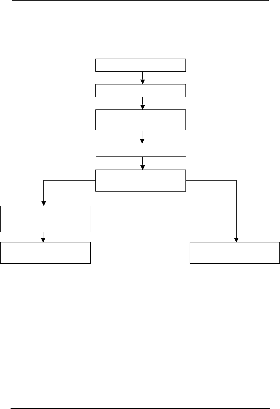
AC5124-10 Specifications
AC5124-10 SpecificationsAC5124-10 Specifications
AC5124-10 Specifications
11/24/03 54
The figure below provides an example of the initialization sequence for both Clients and Servers
following the configuration of EEPROM parameters. This occurs only in API Mode.
Figure
Figure Figure
Figure 2
22
2 - API Mode Initialization
- API Mode Initialization - API Mode Initialization
- API Mode Initialization
Apply Power
Wait for CTS logic low
Host issues
RF Enable
RF EnableRF Enable
RF Enable
command
Client issues
In Range
In RangeIn Range
In Range
command to Host with Server
address
Server can now transmit or
receive data
Client can now transmit or
receive data
Host reads EEPROM for IEEE
source address
Host awaits
Acknowledge
AcknowledgeAcknowledge
Acknowledge
Client Transceiver
Client TransceiverClient Transceiver
Client Transceiver Server Transceiver
Server TransceiverServer Transceiver
Server Transceiver
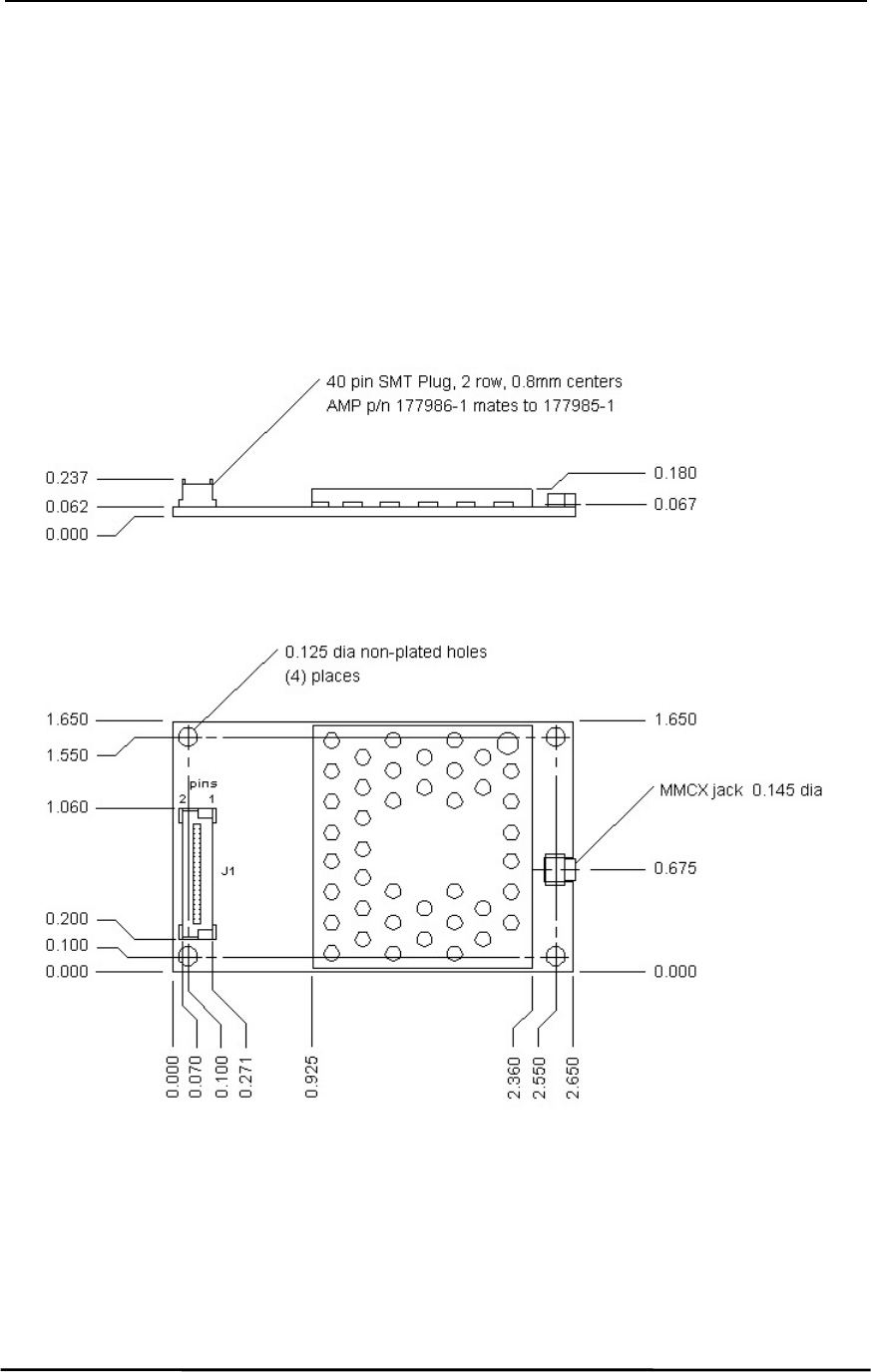
AC5124-10 Specifications
AC5124-10 SpecificationsAC5124-10 Specifications
AC5124-10 Specifications
11/24/03 55
9.
9.9.
9. Mechanical Overview
Mechanical OverviewMechanical Overview
Mechanical Overview
The AC5124 measures 1.65”W x 2.65”L. Critical parameters are as follows:
• J1
J1J1
J1 – 40 pin OEM interface connector (AMP P/N 177986-1) mates with AMP P/N 177985-1
• MMCX Jack
MMCX JackMMCX Jack
MMCX Jack – Antenna connector (Telegartner P/N J01341C0081) mates with any
manufacturer’s MMCX plug
Figure
Figure Figure
Figure 3
33
3 – AC5124 with MMCX
– AC5124 with MMCX – AC5124 with MMCX
– AC5124 with MMCX
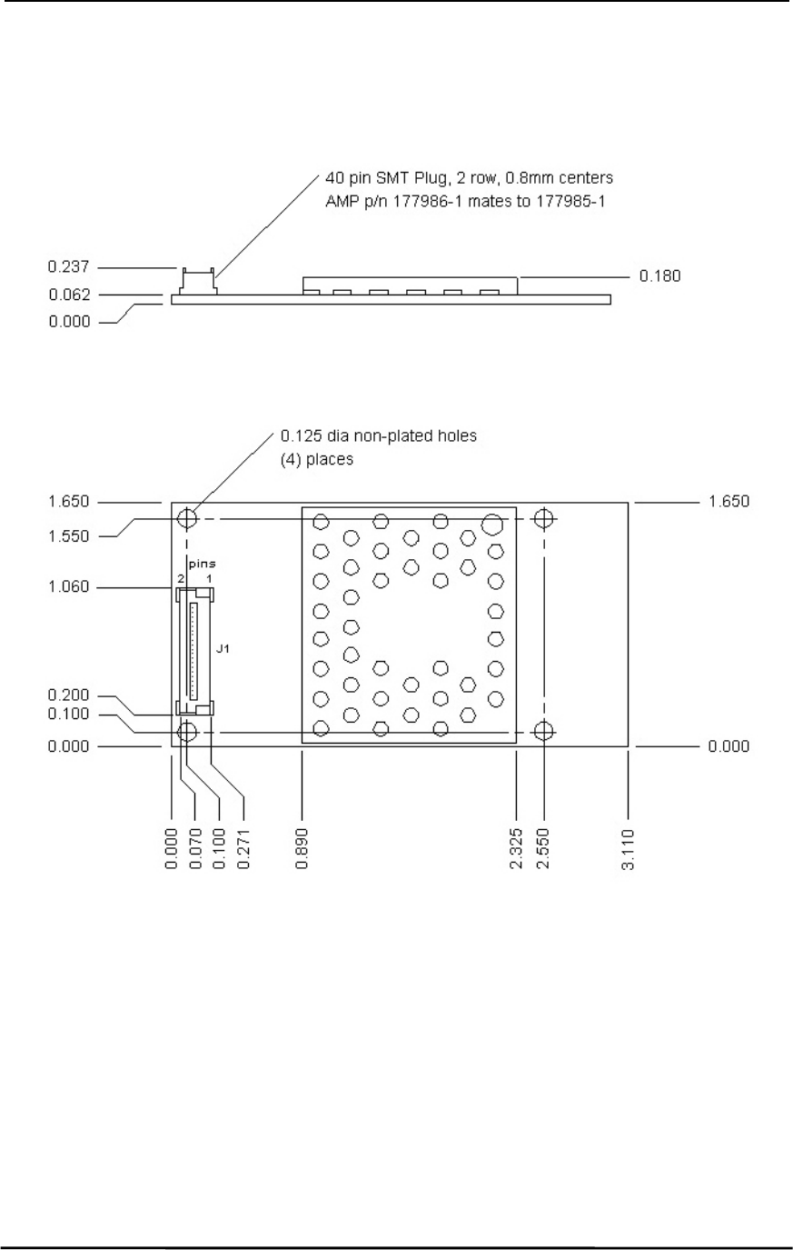
AC5124-10 Specifications
AC5124-10 SpecificationsAC5124-10 Specifications
AC5124-10 Specifications
11/24/03 56
Figure
Figure Figure
Figure 4
44
4 – AC5124 with Integral Antenna
– AC5124 with Integral Antenna – AC5124 with Integral Antenna
– AC5124 with Integral Antenna

AC5124-10 Specifications
AC5124-10 SpecificationsAC5124-10 Specifications
AC5124-10 Specifications
11/24/03 57
10.
10.10.
10. Ordering Information
Ordering InformationOrdering Information
Ordering Information
10.1
10.110.1
10.1 P
PP
PRODUCT
RODUCT RODUCT
RODUCT P
PP
PART
ART ART
ART N
NN
NUMBERS
UMBERSUMBERS
UMBERS
AC5124-10:
AC5124-10:AC5124-10:
AC5124-10: AC5124 with 10mW output power, interface data rates to 882 Kbps, MMCX antenna
connector
AC5124-10A:
AC5124-10A:AC5124-10A:
AC5124-10A: AC5124 with 10mW output power, interface data rates to 882 Kbps, integral
AeroComm NZH microstrip dipole antenna
AC5124-200:
AC5124-200:AC5124-200:
AC5124-200: AC5124 with 200mW output power, interface data rates to 882 Kbps, MMCX antenna
connector
AC5124-200A:
AC5124-200A:AC5124-200A:
AC5124-200A: AC5124 with 200mW output power, interface data rates to 882 Kbps, integral
AeroComm NZH microstrip dipole antenna
10.2
10.210.2
10.2 D
DD
DEVELOPER
EVELOPER EVELOPER
EVELOPER K
KK
KIT
IT IT
IT P
PP
PART
ART ART
ART N
NN
NUMBERS
UMBERSUMBERS
UMBERS
SDK-5124C-10:
SDK-5124C-10:SDK-5124C-10:
SDK-5124C-10: Includes (2) AC5124-10 transceivers, (2) RS232 Serial Adapter Boards, (2) Power
supplies, (2) Serial cables, (2) S191FL-5-RMM-2450S dipole antennas with 5” pigtail
and MMCX connector, configuration/testing software, Integration engineering
support
SDK-5124C-200:
SDK-5124C-200:SDK-5124C-200:
SDK-5124C-200: Includes (2) AC5124-200 transceivers, (2) RS232 Serial Adapter Boards, (2) Power
supplies, (2) Serial cables, (2) S191FL-5-RMM-2450S dipole antennas with 5”
pigtail and MMCX connector, configuration/testing software, Integration
engineering support