Laird Connectivity PROFLEX1 802.15.4 Transceiver Module User Manual PFLX UG 0002 00 17
LS Research, LLC 802.15.4 Transceiver Module PFLX UG 0002 00 17
Contents
- 1. Manual Host Protocol Guide
- 2. Manual User Guide
Manual User Guide

The information in this document is subject to change without notice.
Confirm the data is current by downloading the latest revision from www.lsr.com.
PFLX-UG-0002-00-17 Copyright © 2009 LS Research, LLC Page 1 of 29
PRO-FLEX SERIES
TRANSCEIVER MODULES
User’s Guide
Powered By
Last updated
Thursday, June 25, 2009

PRO-FLEX TRANSCEIVER MODULES
USER’S GUIDE
The information in this document is subject to change without notice.
Confirm the data is current by downloading the latest revision from www.lsr.com.
PFLX-UG-0002-00-17 Copyright © 2009 LS Research, LLC Page 2 of 29
Table of Contents
1Introduction ..................................................................................................................... 3
1.1
Purpose & Scope ....................................................................................................................... 3
1.2
Audience .................................................................................................................................... 3
1.3
Applicable Documents ............................................................................................................... 3
1.4
Revision History ......................................................................................................................... 3
2Quick Start ....................................................................................................................... 4
2.1
Operational Overview ................................................................................................................ 4
2.2
Software Installation .................................................................................................................. 4
2.3
Setting up TI Z-Stack ................................................................................................................. 4
2.4
Modifying Include Directories .................................................................................................... 4
2.5
Hardware Connections .............................................................................................................. 5
2.6
PER Test ................................................................................................................................... 5
2.7
Ping-Pong Test ........................................................................................................................ 11
3Development Board Overview ..................................................................................... 14
3.1
Jumpers ................................................................................................................................... 14
4 Hardware Setup……………………………………………………………………………….17
5Writing Application Firmware ...................................................................................... 18
5.1
Development Tools .................................................................................................................. 18
5.2
Debugging ............................................................................................................................... 20
5.3
In-House Programming ........................................................................................................... 21
5.4
Production Programming ......................................................................................................... 21
6ModFLEX Development Board ..................................................................................... 22
6.1
Schematics .............................................................................................................................. 22
6.2
Revision History ....................................................................................................................... 24
7Agency Statement………………………………………………………………………….26
8 Contacting LS Research……………………………………………………………………..29
PRO-FLEX TRANSCEIVER MODULES
USER’S GUIDE
The information in this document is subject to change without notice.
Confirm the data is current by downloading the latest revision from www.lsr.com.
PFLX-UG-0002-00-17 Copyright © 2009 LS Research, LLC Page 3 of 29
1 Introduction
1.1 Purpose & Scope
The purpose of this document is to provide details regarding the setup and use of the
Pro-FLEX series transceiver module development board. This document covers how to
use the preinstalled (Ping Pong Test) demo firmware, a description of the development
board and its features, and a brief tutorial on how to download customer-specific
application firmware.
This document is applicable to hardware revision B of the ModFLEX Development
Board.
1.2 Audience
This document is intended to be read by engineers and technical management. A
general knowledge of common engineering practices is assumed.
1.3 Applicable Documents
Pro-FLEX Datasheet (LSR)
Pro-FLEX Serial Host Protocol (LSR
1.4 Revision History
Date Change Description Revision
Initial release. 1.0
Table 1 Revision History

PRO-FLEX TRANSCEIVER MODULES
USER’S GUIDE
The information in this document is subject to change without notice.
Confirm the data is current by downloading the latest revision from www.lsr.com.
PFLX-UG-0002-00-17 Copyright © 2009 LS Research, LLC Page 4 of 29
2 Quick Start
2.1 Operational Overview
The quick start demonstration presented in this chapter is referred to as the Ping Pong
Test. The Ping Pong Test allows an end user to easily verify communication between
two transceivers and get a feel for the quality of the link via feedback of the flashing
LEDs.
Running the Ping Pong Test requires the use of two (2) development boards. One
board will be the master (or transmitter), and the other board will be the slave (or
receiver). The master periodically transmits packets to the slave. If the slave receives
and verifies the packet, it will flash its LEDs and transmit an acknowledgement to the
master. If the master receives and verifies the acknowledgement, it will flash its LEDs.
In normal ping pong mode, LEDs indicate signal strength (two LEDs on indicate high
signal strength, one LED indicates low signal strength). If the LEDs do not light, the
packet or acknowledgement was not received.
2.2 Software Installation
The included software is an IAR Systems Embedded Workbench for MSP430 (rev.
4.11B) project. As a result, this development environment should be installed on the
development PC. Also, the latest version of the TI ZigBee stack should be installed on
the development PC. The ZigBee stack is available on the TI web site. It should be
noted that the included Pro-FLEX firmware project only uses the 802.15.4 MAC API of
the ZigBee stack.
To install the firmware unzip the files to the C:\Texas Instruments\ZStack-2.2.0-
1.3.0\Projects directory of the TI ZigBee stack. This is assuming that ZigBee stack was
installed into the default directory structure.
Once the firmware is installed, the IAR workspace file should be in C:\Texas
Instruments\ZStack-2.2.0-1.3.0\Projects\ProFlex01. The workspace filename is
Proflex01.eww.
2.3 Setting up TI Z-Stack
TBD
2.4 Modifying Include Directories
TBD
For additional information relating to the TI Z-Stack, refer to the documentation folder
installed with Z-Stack:
Start
All Programs
Texas Instruments
Z-Stack
Documentation
PRO-FLEX TRANSCEIVER MODULES
USER’S GUIDE
The information in this document is subject to change without notice.
Confirm the data is current by downloading the latest revision from www.lsr.com.
PFLX-UG-0002-00-17 Copyright © 2009 LS Research, LLC Page 5 of 29
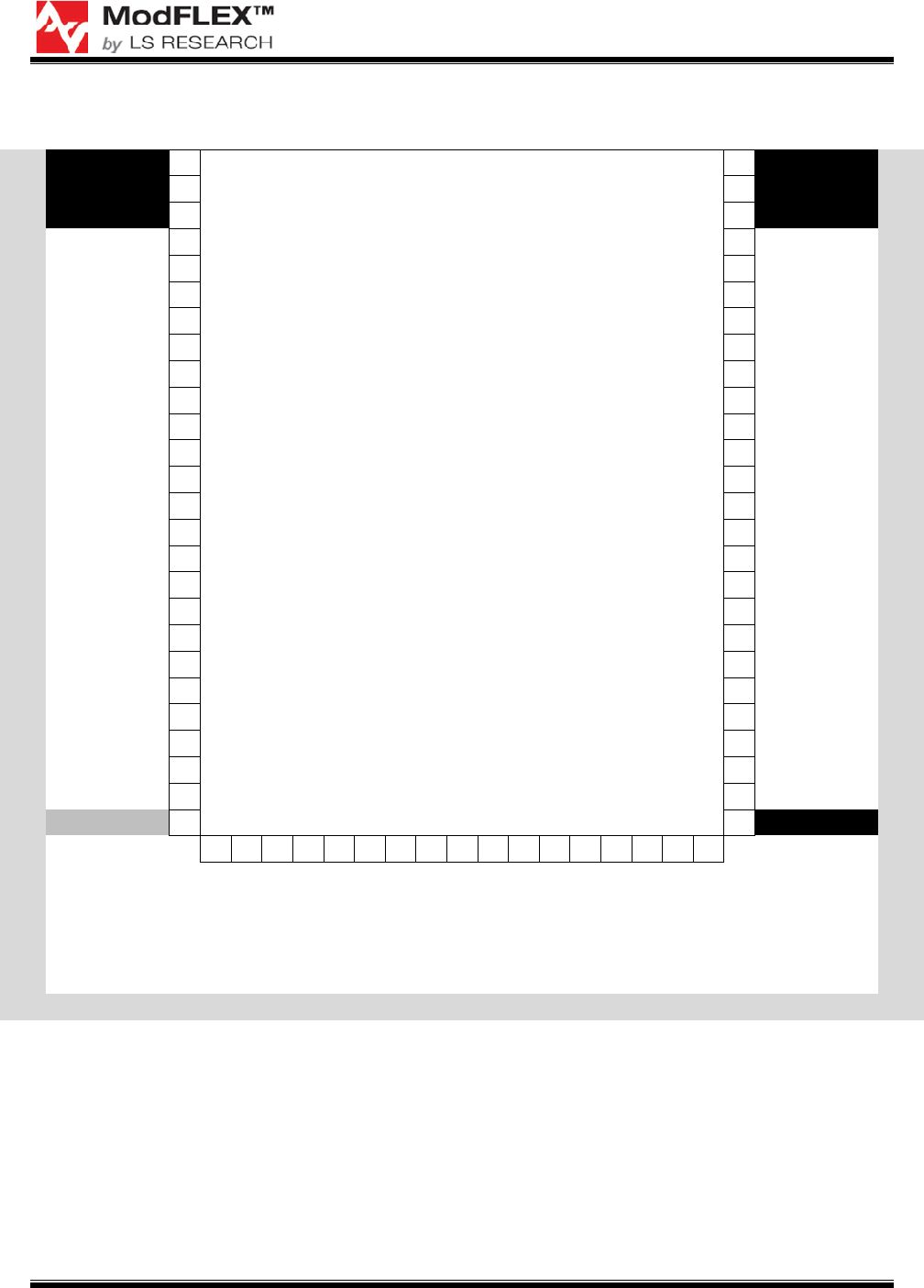
2.5 Hardware Connections
MCU#
GND
1
Texas Instruments
MSP430F5437
69
GND
MCU#
-
GND
2 68
GND
-
-
GND
3 67
GND
-
-
NC
4 66
NC
-
-
NC
5 65
NC
-
-
NC
6 64
NC
-
-
NC
7 63
NC
-
-
NC
8 62
NC
-
74
JTAG - TMS
9 61
SPI - MOSI
56
73
JTAG - TDI
10 60
SPI - MISO
57
75
JTAG - TCK
11 59
SPI - CLK
41
72
JTAG - TDO
12 58
SPI - SS
55
71
JTAG - TEST
13 57
IIC - SDA
42
76
JTAG - /RESET
14 56
IIC - SCL
54
9
VREF+
15 55
GPIO 16
29
10
VERF-
16 54
GPIO 15
28
77
CMP+
17 53
GPIO 14
27
78
CMP-
18 52
GPIO 13
26
79
CMPOUT
19 51
GPIO 12
25
80
ADC1
20 50
GPIO 11
18
1
ADC2
21 49
GPIO 10
17
2
ADC3
22 48
GPIO 09
8
3
ADC4
23 47
GPIO 08
7
4
ADC5
24 46
GPIO 07
60
5
ADC6
25 45
GPIO 06
61
-
VCC - 3V3DC
26 44
GND
-
27 28 29 30 31 32 33 34 35 36 37 38 39 40 41 42 43
TMR/PWM 1
TMR/PWM 2
TMR/PWM 3
TMR/PWM 4
TMR/PWM 5
TMR/PWM 6
TMR/PWM 7
TMR/PWM 8
UART - TX
UART - RX
UART - CTS
UART - RTS
GPIO 1
GPIO 2
GPIO 3
GPIO 4
GPIO 5
MCU# 53 52 48 47 46 45 44 43 39 40 58 59 66 65 64 63 62 MCU#
Figure 1 Pro-FLEX MCU Interconnects
2.6 PER Test
To run the PER test you will need these items:
Two Pro-FLEX Development Boards with latest software
Pro-FLEX Test Tool (PC Software)
PC running Windows XP
Two USB cables
PRO-FLEX TRANSCEIVER MODULES
USER’S GUIDE
The information in this document is subject to change without notice.
Confirm the data is current by downloading the latest revision from www.lsr.com.
PFLX-UG-0002-00-17 Copyright © 2009 LS Research, LLC Page 6 of 29
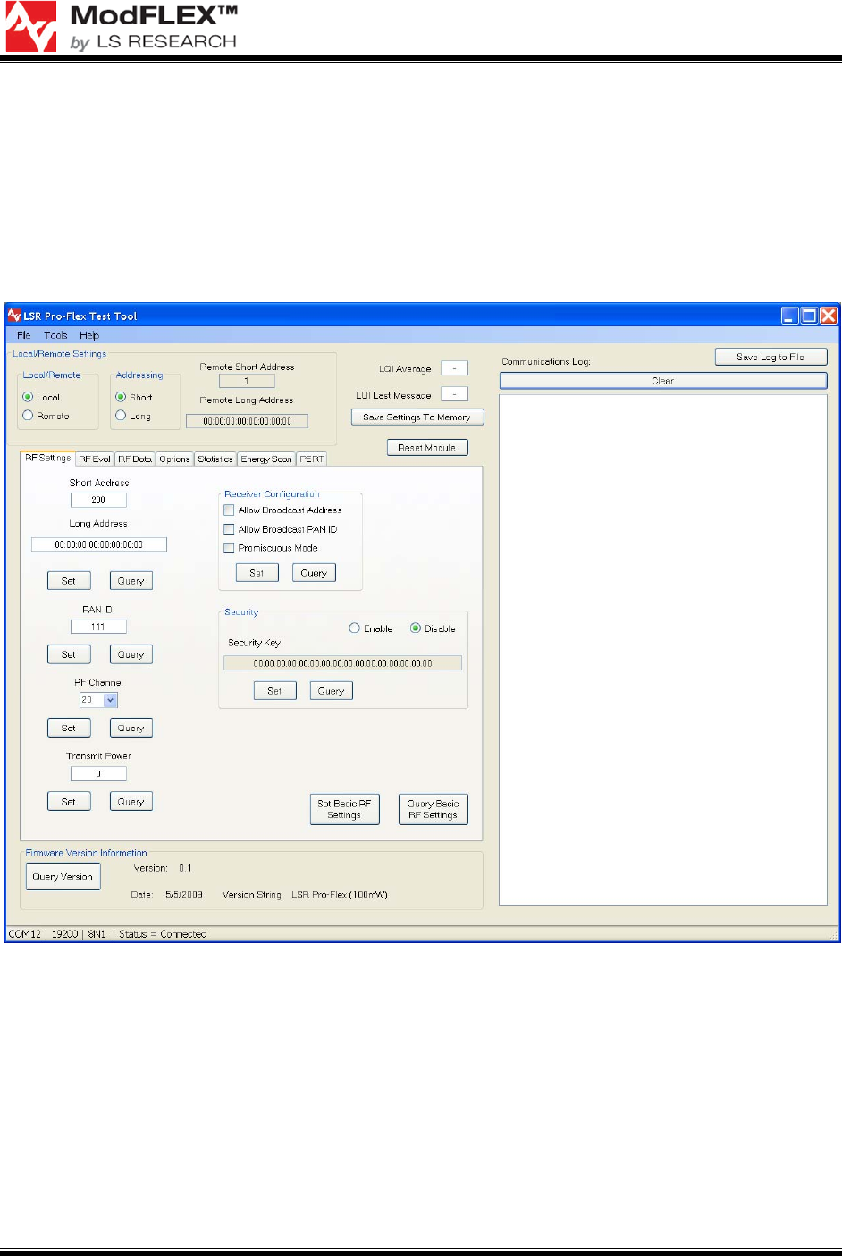
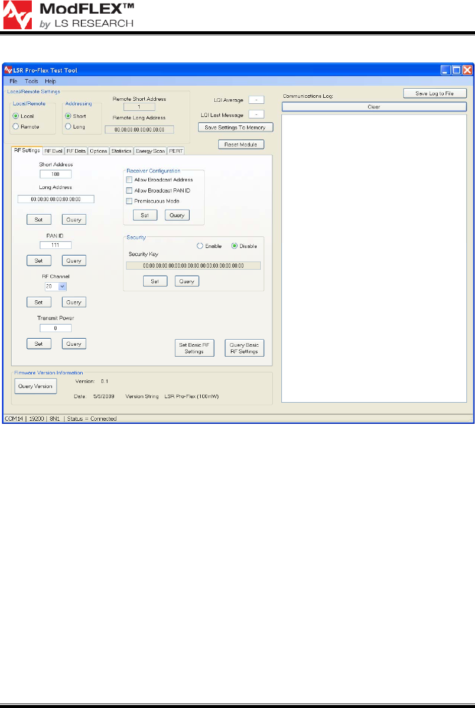
2.6.1 Receiver Setup
Setup a board as a receiver with these settings, for example, as shown in Figure 2:
Short Address: 200
Pan ID: 111
RF Channel: 20
Tx Power: 0
Figure 2 PER Test Receiver RF Settings
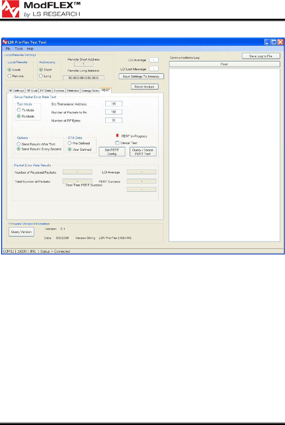
Test Mode
Tx Mode – Board is transmitter
Rx Mode – Board is receiver
Options
Send Results after test – results are sent back to host only after test is completed.

PRO-FLEX TRANSCEIVER MODULES
USER’S GUIDE
The information in this document is subject to change without notice.
Confirm the data is current by downloading the latest revision from www.lsr.com.
PFLX-UG-0002-00-17 Copyright © 2009 LS Research, LLC Page 7 of 29
Send Results every second – results are sent back to host on a 1s periodic basis. This is the
preferred option for the test tool, because you get instant feedback that the test is working
and how well it is working.
OTA Data
N/A for PERT Rx
Query / Cancel
Sends out Host Message Type 0x43.
Used by Host to obtain results of PERT Test
PERT Test in Rx can end in one of three ways:
o 100% of packets are received
o The OTA transmit count = Number of Packets to Receive
o Host cancel request. Since it cannot be guaranteed that the last packet will be received,
it is the responsibility of the host to ensure the test is canceled.
If cancel is selected it will cancel the current test
“PERT In-Progress” is filled in based on query results. Red = no test in progress, green =
test in progress
Setup Packet Error Rate Test
Src Transceiver Address: 100 (who to expect message from)
Number of Packets: 100 (number of RF packets (5-65535). Must match PERT Tx selection.
Number of Bytes: 30 (number of user bytes in packet. Range is 1-105) Must match PERT
Tx selection.
Packet Error Rate Results
Filled in when results are received based on options above.
“Number of Received Packets” – keeps count of how many packets were rx’d
“Total Number of Packets” – configured in UART message above. Used to calculate PERT
success.
LQI Average – the average LQI of Rx’d messages
PERT Success – The number of rx’d packets / total number of packets. Not valid until end of
test.
Real Time PERT Success – The number of rx’d packets/ number of tx’d packets. The
number of Tx’d packets is determined from the count in the OTA data.
PRO-FLEX TRANSCEIVER MODULES
USER’S GUIDE
The information in this document is subject to change without notice.
Confirm the data is current by downloading the latest revision from www.lsr.com.
PFLX-UG-0002-00-17 Copyright © 2009 LS Research, LLC Page 8 of 29
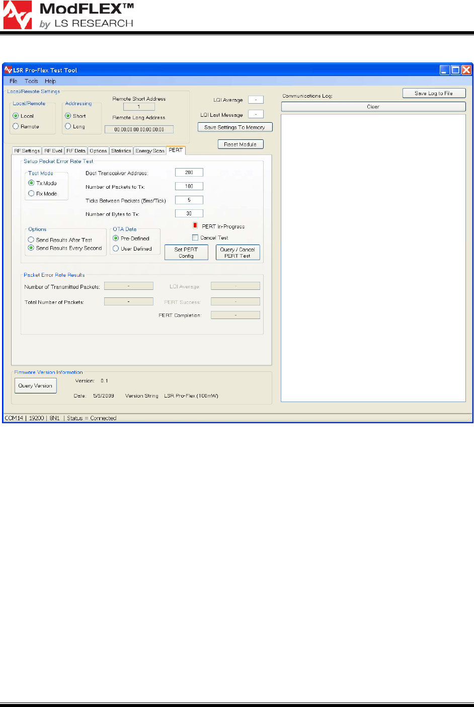
Figure 3 Receiver PERT Tab
2.6.2 Transmitter Setup
Setup a board as a transmitter with these setting, for example, as shown in Figure 4:
Short Address: 100
Pan ID: 111
RF Channel: 20
Tx Power: 0
PRO-FLEX TRANSCEIVER MODULES
USER’S GUIDE
The information in this document is subject to change without notice.
Confirm the data is current by downloading the latest revision from www.lsr.com.
PFLX-UG-0002-00-17 Copyright © 2009 LS Research, LLC Page 9 of 29
Figure 4 PER Test Transmitter RF Settings
On the PERT tab, configure these test settings, as shown in Figure 5:
Test Mode
Tx Mode – Board is transmitter
Rx Mode – Board is receiver
Options
Send Results after test – results are sent back to host only after test is completed.
Send Results every second – results are sent back to host on a 1s periodic basis. This is the
preferred option for the test tool, because you get instant feedback that the test is working
and how well it is working.
OTA Data
User defined – user can enter ASCII data to be transmitted. When this is selected the
“Number of Bytes to Transmit” is hidden. This is not shown below.
Pre defined – sequential data starting at 1 and ending at Number of Bytes to Transmit is sent.
In either case the prefix for this data is amended.

PRO-FLEX TRANSCEIVER MODULES
USER’S GUIDE
The information in this document is subject to change without notice.
Confirm the data is current by downloading the latest revision from www.lsr.com.
PFLX-UG-0002-00-17 Copyright © 2009 LS Research, LLC Page 10 of 29
o OTA packet type – 0x71 (1 byte)
o Current Message Number (0-65535) two bytes
o Total Number of Messages (0-65535) two bytes
Query / Cancel
Sends out Host Message Type 0x43.
PERT Test in Tx will end in one of two ways:
o 100% of packets are transmitted
o Host cancel
If cancel is selected it will cancel the current test
“PERT In-Progress” is filled in based on query results. Red = no test in progress, green =
test in progress
Setup Packet Error Rate Test
Dest Transceiver Address: 200 (who message is being sent to)
Number of Packets: 100 (number of RF packets (5-65535)
Time between Packets: 20 (in terms of 5mS ticks. A selection of 5 would sent out packets
every 5x5mS or 25mS). Range is 1-255.
Number of Bytes: 30 (number of user bytes in packet. Range is 1-105)
Packet Error Rate Results
Filled in when results are received based on options above
The PERT Completion uses the number of packets sent/total number of packets to calculate
how far into the test we are.
LQI Average and PERT Success are grayed out because they are N/A on the TX side
PRO-FLEX TRANSCEIVER MODULES
USER’S GUIDE
The information in this document is subject to change without notice.
Confirm the data is current by downloading the latest revision from www.lsr.com.
PFLX-UG-0002-00-17 Copyright © 2009 LS Research, LLC Page 11 of 29
Figure 5 Transmitter PERT Tab
2.7 Ping-Pong Test
To perform the ping-pong test (without the use of the ModFLEX Development Board),
the Pro-FLEX module will require external hardware connections. A nominal 3.3 volt DC
power supply should be connected to the 3V3DC pin shown in Figure 1. Also, a ground
connection is required. Also, 4 LEDs should be connected to pins TMR/PWM1 through
TMR/PWM3. The cathode of each LED should be each pin. The anode of each LED
should be connected to the 3.3 V power supply through a nominal resistor value of 470
ohms. Each output can sink up to 15 mA to turn on each LED. The outputs are set to
high strength mode in the firmware. The TMR/PWM1 output should have a green LED.
The TMR/PWM2 output should have a yellow LED.
The TMR/PWM5 pin is configured as an input to initiate the ping-pong test mode. This
pin should be connected to ground through a momentary contact normally open (NO)
push button switch. This switch is referred to as the user button in the subsequent
instructions. Also, the RESET pin should be connected to ground through a momentary
contact normally open (NO) push button switch. This switch is referred to as the reset
button in the subsequent instructions.

PRO-FLEX TRANSCEIVER MODULES
USER’S GUIDE
The information in this document is subject to change without notice.
Confirm the data is current by downloading the latest revision from www.lsr.com.
PFLX-UG-0002-00-17 Copyright © 2009 LS Research, LLC Page 12 of 29
2.7.1 Master / Slave Selection
Master device setup
1. Press the reset button and the user button simultaneously.
2. Release the reset button.
3. Wait until the green LED is lit, then release the user button.
Slave device setup
1. Press the reset button and the user button simultaneously.
2. Release the reset button.
3. Quickly release the user button (Release within 1.5 seconds of performing step 2
above).
2.7.2 Association Mode
In association mode, the red LED will flash rapidly on each board until it has linked with
the other device. At this point, the red LED will go out and the green LED will begin to
flash rapidly for approximately two seconds. Association mode lasts up to thirty seconds
after power up, so the master and slave pair should be powered up at relatively the
same time. If the transceivers link, they will enter the ping pong mode after association
mode times out. However, if they do not link, they will not communicate and the
sequence must be repeated from the point of master/slave selection at power up.
2.7.3 Ping Pong Mode
In ping pong mode, the master and slave boards will flash one or two LEDs with each
packet (slave) or acknowledge (master) received, based on message signal strength.
Refer to Table 2 below for a description of the LEDs versus signal strength. In case
there is a lot of traffic on the default channel, it is possible to change the channel.
Red LED Green LED Signal Strength
OFF OFF None
ON OFF Marginal
OFF ON Good
ON ON Excellent
Table 2 LED Signal Strength Definitions
2.7.4 Changing RF Channels
Note that this can only be performed if boards have been associated.

PRO-FLEX TRANSCEIVER MODULES
USER’S GUIDE
The information in this document is subject to change without notice.
Confirm the data is current by downloading the latest revision from www.lsr.com.
PFLX-UG-0002-00-17 Copyright © 2009 LS Research, LLC Page 13 of 29
While in the ping pong mode, the current channel can be changed to one of four other
unique channels (four channels total). This is accomplished by holding the User Button
for approximately two seconds, at which point the yellow LED will be lit steady. Once
the push button is released, the current channel option number (one through four) is
displayed by a series of flashes on the red LED. Each short push button press will
increment the channel option number and display it with a given number of flashes on
the red LED. To accept the last selected channel, hold the push button until the green
LED goes out (approximately two seconds). After again releasing the button, the device
will return to the ping pong mode.
Note that both the master and slave devices must be set to the same
channel option number for the pair to communicate, and each board must
be individually set to that given channel option number.
PRO-FLEX TRANSCEIVER MODULES
USER’S GUIDE
The information in this document is subject to change without notice.
Confirm the data is current by downloading the latest revision from www.lsr.com.
PFLX-UG-0002-00-17 Copyright © 2009 LS Research, LLC Page 14 of 29
3 Development Board Overview
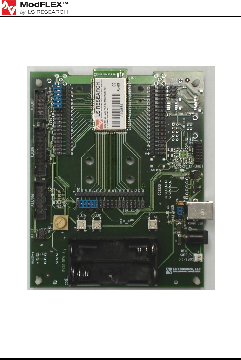
Figure 6 shows a ModFLEX development board, which is discussed throughout the
remainder of this section.
Figure 6 ModFLEX Development Board
3.1 Jumpers
3.1.1 Development Jumper Headers
The three rows of jumper headers on the east, south, and west sides of the installed
Pro-FLEX module can be used to control the interconnects of the Pro-FLEX module to
PRO-FLEX TRANSCEIVER MODULES
USER’S GUIDE
The information in this document is subject to change without notice.
Confirm the data is current by downloading the latest revision from www.lsr.com.
PFLX-UG-0002-00-17 Copyright © 2009 LS Research, LLC Page 15 of 29
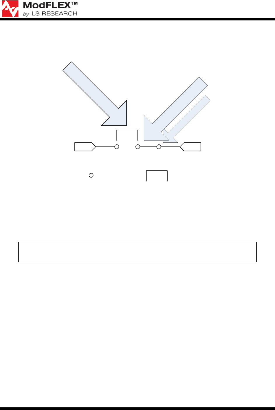
the outside world. For the sake of discussion, Figure 7 will be used to describe the
various Pro-FLEX module interconnect jumper settings.
To development
board circuitry
To module
Add jumper to connect to
development board circuitry.
Board edge side
Module side
or here.
Header pin
Or, add an interface
to your circuit here...
Jumper
Figure 7 Interface Pins Layout
To connect the Pro-FLEX module pins to their development board periphery circuits the
respective pins need to be jumpered together. To isolate the Pro-FLEX module, remove
the jumpers. The jumper pins can be used to connect the Pro-FLEX module to an
application circuit and/or test/debug equipment, such as a multi-meter or oscilloscope.
In order to program or debug the Pro-FLEX module, the jumpers bridging
module pins 9 through 14 will need to be in place.
Additional details regarding Pro-FLEX module pin configurations can be found in the
Pro-FLEX datasheet.
3.2 Power Supply Jumpers
3.2.1 Rev. C and Later
TBD
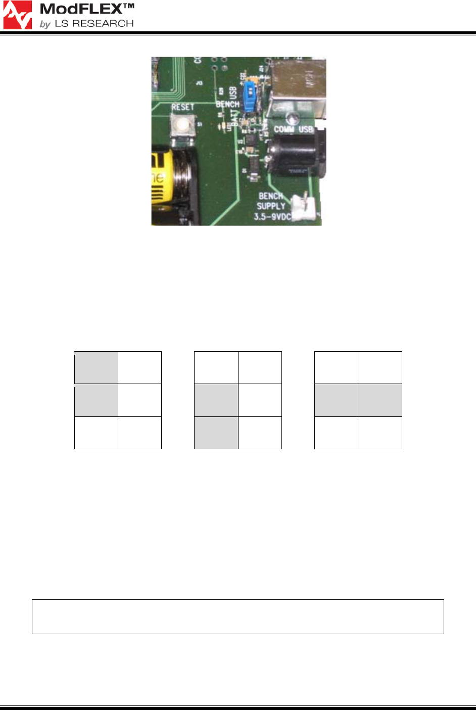
3.2.2 Rev. B and Earlier
Figure 8 shows the power supply jumpers on the Pro-FLEX development board, which
are located behind the female USB-B plug.
PRO-FLEX TRANSCEIVER MODULES
USER’S GUIDE
The information in this document is subject to change without notice.
Confirm the data is current by downloading the latest revision from www.lsr.com.
PFLX-UG-0002-00-17 Copyright © 2009 LS Research, LLC Page 16 of 29
Figure 8 Power Supply Jumpers
Figure 9 Power Supply Jumper Settings
shows the configurations of the power supply jumper settings to select from the various
power supply options: USB, Batteries, or Bench Supply / AC Adapter.
USB Batteries
Bench Supply /
AC Adapter
■ ■ ■ ■ ■ ■
■ ■ ■ ■ ■ ■
■ ■ ■ ■ ■ ■
Figure 9 Power Supply Jumper Settings
3.3 Debug Headers
Because the same development board is used for all of the ModFLEX series transceiver
modules, the Pro-FLEX development board is populated with debug headers /
development ports for the Si-FLEX, Wi-FLEX, and E-FLEX series transceiver modules,
in addition to having a debug header for Pro-FLEX modules. Each of these
development ports is intended for use only with their respective ModFLEX series
transceiver module.
Please note that using the debug headers for purposes other than their
intended use is not advised and may void the module warranty.
When developing with the Pro-FLEX transceiver module, be sure to use the Pro-FLEX
debugging header described in section 2.5.

PRO-FLEX TRANSCEIVER MODULES
USER’S GUIDE
The information in this document is subject to change without notice.
Confirm the data is current by downloading the latest revision from www.lsr.com.
PFLX-UG-0002-00-17 Copyright © 2009 LS Research, LLC Page 17 of 29
4 Hardware Setup
TBD
PRO-FLEX TRANSCEIVER MODULES
USER’S GUIDE
The information in this document is subject to change without notice.
Confirm the data is current by downloading the latest revision from www.lsr.com.
PFLX-UG-0002-00-17 Copyright © 2009 LS Research, LLC Page 18 of 29
5 Writing Application Firmware
5.1 Development Tools
Developing custom firmware for the Pro-FLEX series transceiver modules requires the
use of the MSP-FET430UIF debugging interface from Texas Instruments and IAR
Embedded Workbench from IAR Systems. It is also recommended that you obtain a
license for Sensor Network Analyzer from Daintree Networks, as this is a very useful and
very powerful 802.15.4 RF sniffer.
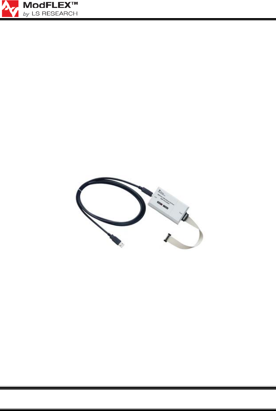
5.1.1 Texas Instruments MSP-FET430UIF
Custom firmware development can be done on the Pro-FLEX module using
development tools available thought TI. As shown in Figure 10, a MSP-FETUIF USB
Interface is required. It plugs directly into the ModFLEX Development Board (see Figure
6), and can easily be adapted to other hardware. See the Texas Instruments website
(www.ti.com) for more information and how to order.
Figure 10 MSP-FET430UIF
1
5.1.2 IAR Systems Embedded Workbench for MSP430
Also required is Embedded Workbench for TI MSP430 from IAR Systems. IAR
Embedded Workbench for MSP430 provides extensive support for devices in MSP430
and MSP430X families and generates very compact and efficient code. Built-in plugins
for various hardware debug systems and RTOSs are included in the standard edition.
KickStart, Evaluation, Baseline, and Full editions are available from IAR Systems. Visit
www.iar.com for additional information.
1
The MSP-FET430UIF will be needed to develop firmware for Pro-FLEX series transceiver modules with
the Texas Instruments chipset solution. Visit www.ti.com for additional details.
PRO-FLEX TRANSCEIVER MODULES
USER’S GUIDE
The information in this document is subject to change without notice.
Confirm the data is current by downloading the latest revision from www.lsr.com.
PFLX-UG-0002-00-17 Copyright © 2009 LS Research, LLC Page 19 of 29
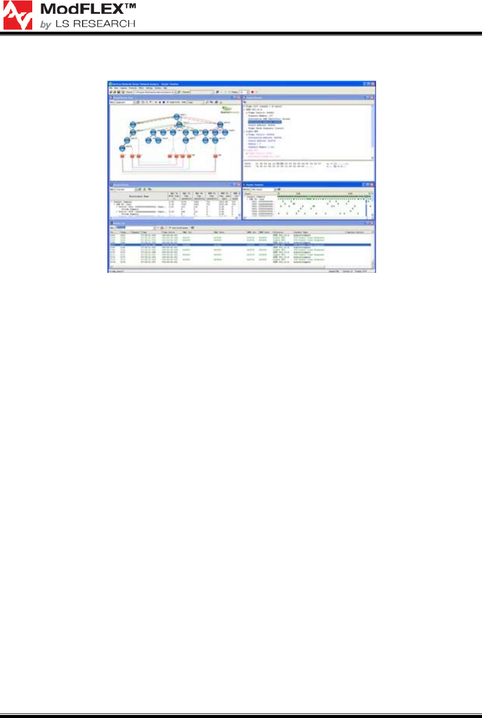
5.1.3 Daintree Networks Sensor Network Analyzer
Figure 11 Daintree Networks Sensor Network Analyzer RF Sniffer
Daintree Network’s Sensor Network Analyzer features include a powerful protocol
decoder that allows you to drill down to packet, field, and byte level; unique visualization
capabilities that allow you to view all network devices and interactions simultaneously;
customization options including filtering, labeling and color-coding to make it easy to
locate packets of interest; performance measurements for 802.15.4 and ZigBee; and
intuitive tools that make it easy to perform complex functions such as multi-node and
multi-channel capture and ZigBee commissioning. Visit www.daintree.net for additional
information.
5.1.4 Daintree Networks Sensor Network Adapter
While the Daintree Networks Sensor Network Analyzer is compatible with the
MSP430F5437, LSR recommends using the Daintree 2400E Sensor Network Adapter in
conjunction with Daintree’s Sensor Network Analyzer software. The Daintree Networks
2400E Sensor Network Adapter, see Figure 12, is a capture accessory that acts as an
observation and control point enabling the use of Daintree's Sensor Network Analyzer
(SNA) software in live wireless embedded networks. More than just a capture device,
this versatile Adapter can also join live ZigBee networks to actively poll and commission
devices. The 2400E Sensor Network Adapter provides both Ethernet and USB
interfaces. It is portable and light-weight making it suitable for use in remote locations. A
more detailed overview of the 2400E Sensor Network Adapter can be found at
http://www.daintree.net/products/adapter.php.
PRO-FLEX TRANSCEIVER MODULES
USER’S GUIDE
The information in this document is subject to change without notice.
Confirm the data is current by downloading the latest revision from www.lsr.com.
PFLX-UG-0002-00-17 Copyright © 2009 LS Research, LLC Page 20 of 29
Figure 12 Sensor Network Adapter
5.1.5 TI SmartRF Protocol Packet Sniffer
The TI SmartRF Protocol Packet Sniffer is a free IEEE 802.15.4 packet sniffer, that can
be used with any CC24xx or CC25xx development kit from Texas Instruments. The
Packet Sniffer is a PC software application used to display and store RF packets
captured with a listening RF Device. The RF Device is connected to the PC with an USB
cable. Various RF protocols are supported. The Packet Sniffer filters and decodes
packets and displays them in a convenient way, with options for filtering and storage to a
binary file format.
2
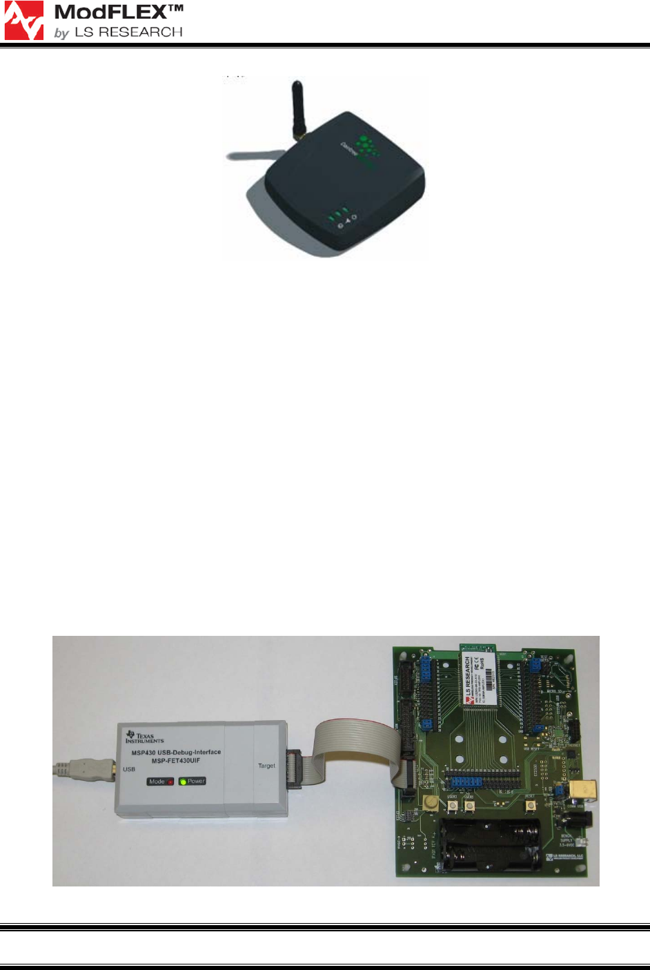
5.2 Debugging
When your custom firmware is ready for debugging, connect the MSP-FET430UIF to the
ModFLEX development board fitted with a Pro-FLEX series transceiver module. From
the Project menu, select Debug, or, alternatively, click the Debugger button in the IAR
Embedded Workbench toolbar. See the MSP430 IAR Embedded Workbench® IDE
User Guide for additional details. This document can be found through the Help menu of
Embedded Workbench, after it is installed on your machine.
Figure 13 Debugging Pro-FLEX Custom Firmware via MSP-FET430UIF
2
http://focus.ti.com/docs/toolsw/folders/print/packet-sniffer.html
PRO-FLEX TRANSCEIVER MODULES
USER’S GUIDE
The information in this document is subject to change without notice.
Confirm the data is current by downloading the latest revision from www.lsr.com.
PFLX-UG-0002-00-17 Copyright © 2009 LS Research, LLC Page 21 of 29
5.3 In-House Programming
For programming prototypes in-house, either Embedded Workbench for MSP430 from
IAR Systems or FET-Pro430 from Elprotronic (www.elprotronic.com) can be used.
Detailed instructions for programming your module with Embedded Workbench for
MSP430 or FET-Pro430 can be found in their respective User’s Guides.
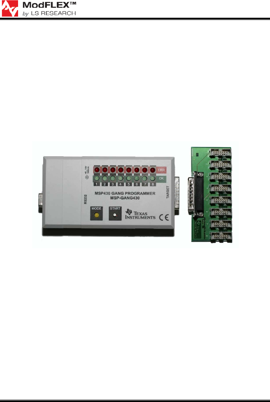
5.4 Production Programming
In place of the MSP-FET430UIF, Texas Instruments recommends using their MSP-
GANG430 programmer, see Figure 14, for production programming. This device allows
for programming of up to eight devices simultaneously. Additional details regarding the
MSP430 Gang Programmer can be found on the Texas Instruments website
(www.ti.com).
Figure 14 MSP430 Gang Programmer

PRO-FLEX TRANSCEIVER MODULES
USER’S GUIDE
The information in this document is subject to change without notice.
Confirm the data is current by downloading the latest revision from www.lsr.com.
PFLX-UG-0002-00-17 Copyright © 2009 LS Research, LLC Page 22 of 29
6 ModFLEX Development Board
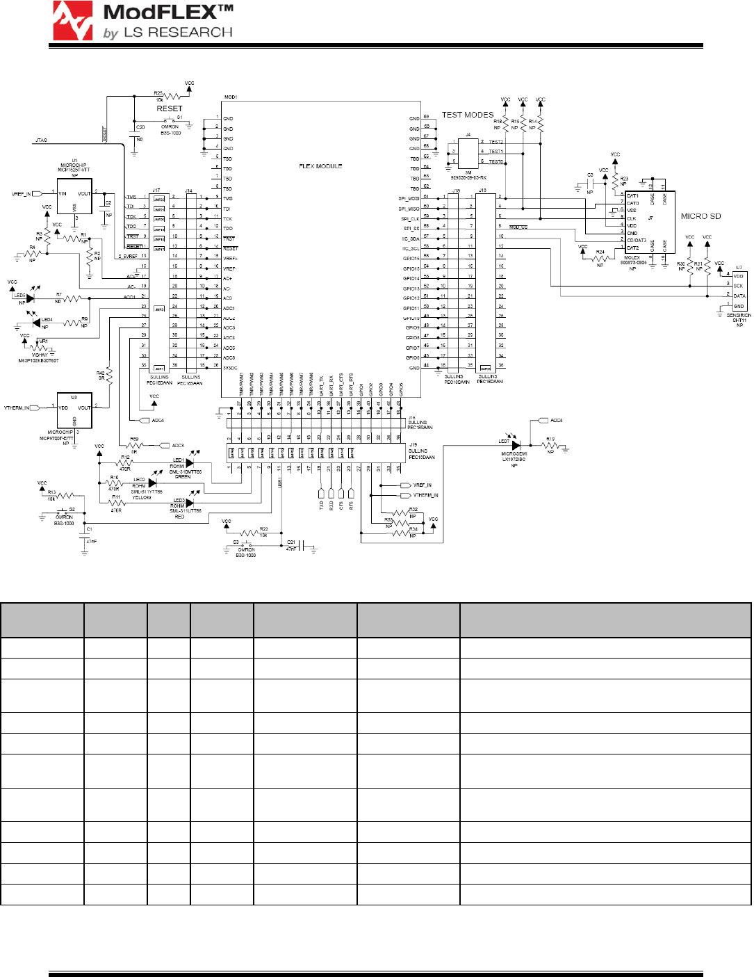
6.1 Schematics
Figure 15 and Figure 16 are the schematics for Rev. C of the ModFLEX development
board. Table 3 specifies the No-Pop components.
Figure 15 ModFLEX Development Board Schematic Page 1 of 2
PRO-FLEX TRANSCEIVER MODULES
USER’S GUIDE
The information in this document is subject to change without notice.
Confirm the data is current by downloading the latest revision from www.lsr.com.
PFLX-UG-0002-00-17 Copyright © 2009 LS Research, LLC Page 23 of 29
Figure 16 ModFLEX Development Board Schematic Page 2 of 2
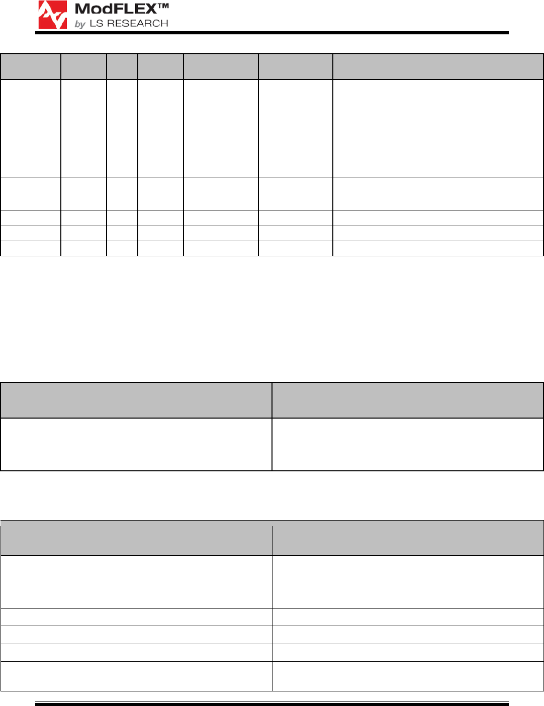
Reference Value Tol. Voltage/
Power Manufacturer Part Number Description
C2 C3 C20 NP 0402 SIZE SMT CERAMIC CAPACITOR
C7 NP 1206 SIZE SMT CERAMIC CAPACITOR
C23 NP
SURFACE MOUNT TANT. CAPACITOR 'A' CASE
SIZE
ISO1 FAIRCHILD H11F1M PHOTOFET OPTOCOUPLER
J6 SULLINS PBC02SAAN 2 PIN 0.1" HEADER
J7 MOLEX 500873-0806
MICRO SD CARD CONNECTOR, SMT W/PUSH
PUSH
J8 HIROSE DF11-12DS-
2DSA(06) 6 POSITION DUAL ROW 2mm SMT RECEPTACLE
J24 3M 929647-02-06-I 6 PIN 0.1" STRIP HEADER
LED4 LED5 RED ROHM SML-311UTT86 0603 SIZE SMT RED LED
LED7 MICROSEMI LX1972IBC AMBIENT LIGHT DETECTOR
MOD1 FLEX MODULE
PRO-FLEX TRANSCEIVER MODULES
USER’S GUIDE
The information in this document is subject to change without notice.
Confirm the data is current by downloading the latest revision from www.lsr.com.
PFLX-UG-0002-00-17 Copyright © 2009 LS Research, LLC Page 24 of 29
Reference Value Tol. Voltage/
Power Manufacturer Part Number Description
R1 R2 R3 R4
R7 R9 R14
R15 R18
R19 R20
R21 R23
R24 R30
R31 R32
R33 R34
R35 R38
R54 R58
NP THICK FILM 0402 SMT RESISTOR
R64 R65
R66 R67
R68 R69
NP 5% 125mW Any 0805 SURFACE MOUNT RESISTOR
U1 2.5V 1% MICROCHIP MCP1525T-I/TT 2.5V VOLTAGE REFERENCE
U3 2.5V ±4°C MICROCHIP MCP9700T-E/TT LOW POWER LINEAR ACTIVE THERMISTOR
U7 SENSIRION SHT11 HUMIDITY AND TEMP SENSOR
Table 3 No-Pop Components
6.2 Revision History
6.2.1 Rev. A Schematic Changes
Initial production release.
6.2.2 Rev. B Schematic Changes
Change Description Change Description Continuation and/or Change
Justification
Swap UART TX and RX pins on the Development Board
Right now TX on the silicon labs part is wired to TX on the
Module and same for Rx. Tx of the Module s/b going to
Rx of the SI Labs part and Rx of the Module to RX of the
SI Labs part
Table 4 Rev. B Schematic Changes
6.2.3 Rev. C Schematic Changes
Change Description Change Description Continuation and/or Change
Justification
Rearranged reference designators for LEDs as follows:
Was LED4, now LED1
Was LED6, Now LED4
Was LED1, now LED6
More intuitive and easier to read arrangement
Disconnect J20 pin 3 from J1 pin 2. New supply scheme doesn’t use switch isolation
Connect J1 pin 2 to GND net New supply scheme doesn’t use switch isolation
Connect J20 pin 3 to GND net New supply scheme doesn’t use switch isolation
Insert D2 in series between J20 pin 1 (anode) and J1 pin
1/C18 node (cathode) So the module doesn't burn

PRO-FLEX TRANSCEIVER MODULES
USER’S GUIDE
The information in this document is subject to change without notice.
Confirm the data is current by downloading the latest revision from www.lsr.com.
PFLX-UG-0002-00-17 Copyright © 2009 LS Research, LLC Page 25 of 29
Change Description Change Description Continuation and/or Change
Justification
Insert D1 in series between J1 pin 1 (anode) and D2/C18
node (cathode) So the module doesn't burn
Connect D3 anode to J5 pin 1/Z2 pin 2/C24/U4 pin7/U4
pin 8 node So the module doesn't burn
Connect D3 cathode to D1/D2/C18 node So the module doesn't burn
Connect U2 as described below:
Connect C5 between U2 pin 1 and GND net
Connect U3 pin 3 to GND net
Connect U2 pin 4 and U2 pin 8 to D1/D2/D3/C18 node
Connect R6 between U2 pin 5 and U2 pin 6
Connect C4 in parallel with R6
Connect R5 between U2 pin 6/R6/C4 node and GND net
Higher input Voltage and safety features with new
regulator circuit
Connect C6 between U2 pin 5/R6/C4 node and GND net Higher input Voltage and safety features with new
regulator circuit
Connect C7 between U2 pin 5/R6/C4/C6 node and GND
net
Higher input Voltage and safety features with new
regulator circuit
Connect J2 pin 1 to U2 pin 5/R6/C4/C6/C7 node. Label
node as VREG net New voltage source selection scheme
Connect J2 pin 2 to VCC net New voltage source selection scheme
Connect Q1 as described below:
Connect Q1 pin 1 to GND net
Connect Q1 pin 2 to J2 pin 3. Label net as VBAT
Connect Q1 pin 3 to B1 pin 1
Reverse battery protection
Table 5 Rev. C Schematic Changes

PRO-FLEX TRANSCEIVER MODULES
USER’S GUIDE
The information in this document is subject to change without notice.
Confirm the data is current by downloading the latest revision from www.lsr.com.
PFLX-UG-0002-00-17 Copyright © 2009 LS Research, LLC Page 26 of 29
7 Agency Statements
Federal Communication Commission Interference Statement
This equipment has been tested and found to comply with the limits for a Class B digital
device, pursuant to Part 15 of the FCC Rules. These limits are designed to provide
reasonable protection against harmful interference in a residential installation. This
equipment generates uses and can radiate radio frequency energy and, if not installed
and used in accordance with the instructions, may cause harmful interference to radio
communications. However, there is no guarantee that interference will not occur in a
particular installation. If this equipment does cause harmful interference to radio or
television reception, which can be determined by turning the equipment off and on, the
user is encouraged to try to correct the interference by one of the following measures:
- Reorient or relocate the receiving antenna.
- Increase the separation between the equipment and receiver.
- Connect the equipment into an outlet on a circuit different from that
to which the receiver is connected.
- Consult the dealer or an experienced radio/TV technician for help.
This device complies with Part 15 of the FCC Rules. Operation is subject to the following
two conditions: (1) This device may not cause harmful interference, and (2) this device
must accept any interference received, including interference that may cause
undesired operation.
FCC/IC Caution: Any changes or modifications not expressly approved by the party
responsible for compliance could void the user's authority to operate this equipment.
OEM Responsibility to the FCC Rules and Regulations
The Pro-FLEX Module has been certified per FCC Part 15 and IC RSS-GEN (2007) rules for
integration into products without further testing or certification. To fulfill the FCC and IC
certification requirements the OEM of the Pro-FLEX Module must ensure that the information
provided on the Pro-FLEX Label is placed on the outside of the final product.
The Pro-FLEX Module is labeled with its own FCC ID and IC Number. If the FCC ID and IC
Number are not visible when the module is installed inside another device, then the outside of
the device into which the module is installed must also display a label referring to the enclosed
module. The final end product must be labeled in a visible area with the following:
“Contains Transmitter Module FCC ID: TFB-PROFLEX1”
“Contains Transmitter Module IC: 5969A-PROFLEX1”
or
“Contains FCC ID: TFB-PROFLEX1”
“Contains IC: 5969A-PROFLEX1”

PRO-FLEX TRANSCEIVER MODULES
USER’S GUIDE
The information in this document is subject to change without notice.
Confirm the data is current by downloading the latest revision from www.lsr.com.
PFLX-UG-0002-00-17 Copyright © 2009 LS Research, LLC Page 27 of 29
The OEM of the Pro-FLEX Module must only use the approved antenna(s), which have been
certified with this module.
The OEM of the Pro-FLEX Module must test their final product configuration to comply with
Unintentional Radiator Limits before declaring FCC compliance per Part 15 of the FCC rules
and RSS-GEN (2007) of Industry Canada’s rules.
This transmitter module is authorized to be used in other devices only by OEM
integrators under the following conditions:
1. The antenna(s) must be installed such that a minimum separation distance of 20cm is
maintained between the radiator (antenna) and all persons at all times.
2. The transmitter module must not be co-located or operating in conjunction with any
other antenna or transmitter.
As long as the two conditions above are met, further transmitter testing will not be
required. However, the OEM integrator is still responsible for testing their end-product for
any additional compliance requirements required with this module installed (for
example, digital device emissions, PC peripheral requirements, etc.).
IMPORTANT NOTE: In the event that these conditions cannot be met (for certain
configurations or co-location with another transmitter), then the FCC and IC
authorizations are no longer considered valid and the FCC and IC # cannot be used on
the final product. In these circumstances, the OEM integrator will be responsible for re-
evaluating the end product (including the transmitter) and obtaining a separate FCC
and IC authorization.
The OEM integrator has to be aware not to provide information to the end user regarding
how to install or remove this RF module or change RF related parameters in the user
manual of the end product.
The user manual for the end product must include the following information in a
prominent location:
“To comply with FCC RF radiation exposure requirements, the antenna(s) used for this
transmitter must be installed such that a minimum separation distance of 20cm is
maintained between the radiator (antenna) & user’s/nearby people’s bodies at all times
and must not be co-located or operating in conjunction with any other antenna or
transmitter.”

PRO-FLEX TRANSCEIVER MODULES
USER’S GUIDE
The information in this document is subject to change without notice.
Confirm the data is current by downloading the latest revision from www.lsr.com.
PFLX-UG-0002-00-17 Copyright © 2009 LS Research, LLC Page 28 of 29
INDUSTRY CANADA STATEMENTS
Operation is subject to the following two conditions: (1) this device may not cause
interference, and (2) this device must accept any interference, including interference
that may cause undesired operation of the device.
To reduce potential radio interference to other users, the antenna type and its gain
should be so chosen that the equivalent isotropically radiated power (e.i.r.p.) is not more
than that permitted for successful communication.
This device has been designed to operate with the antennas listed below, and having a
maximum gain of 2.0 dBi. Antennas not included in this list or having a gain greater than
2.0 dBi are strictly prohibited for use with this device. The required antenna impedance is
50 ohms.
Approved Antennas
Nearson DiPole # S131CL-L-PX-2450S
Inverted F Trace
To comply with IC RF exposure limits for general population/uncontrolled exposure, the
antenna(s) used for this transmitter must be installed to provide a separation distance of
at least 20 cm from all persons and must not be collocated or operating in conjunction
with any other antenna or transmitter.

PRO-FLEX TRANSCEIVER MODULES
USER’S GUIDE
The information in this document is subject to change without notice.
Confirm the data is current by downloading the latest revision from www.lsr.com.
PFLX-UG-0002-00-17 Copyright © 2009 LS Research, LLC Page 29 of 29
8 Contacting LS Research
Headquarters LS Research, LLC
W66 N220 Commerce Court
Cedarburg, WI 53012-2636
USA
Tel: 1(262) 375-4400
Fax: 1(262) 375-4248
Website www.lsr.com
Technical Support support@lsr.com
Sales Contact sales@lsr.com
The information in this document is provided in connection with LS Research (hereafter referred to as
“LSR”) products. No license, express or implied, by estoppel or otherwise, to any intellectual property right
is granted by this document or in connection with the sale of LSR products. EXCEPT AS SET FORTH IN
LSR’S TERMS AND CONDITIONS OF SALE LOCATED ON LSR’S WEB SITE, LSR ASSUMES NO
LIABILITY WHATSOEVER AND DISCLAIMS ANY EXPRESS, IMPLIED OR STATUTORY WARRANTY
RELATING TO ITS PRODUCTS INCLUDING, BUT NOT LIMITED TO, THE IMPLIED WARRANTY OF
MERCHANTABILITY, FITNESS FOR A PARTICULAR PURPOSE, OR NON-INFRINGEMENT. IN NO
EVENT SHALL LSR BE LIABLE FOR ANY DIRECT, INDIRECT, CONSEQUENTIAL, PUNITIVE,
SPECIAL OR INCIDENTAL DAMAGES (INCLUDING, WITHOUT LIMITATION, DAMAGES FOR LOSS
OF PROFITS, BUSINESS INTERRUPTION, OR LOSS OF INFORMATION) ARISING OUT OF THE USE
OR INABILITY TO USE THIS DOCUMENT, EVEN IF LSR HAS BEEN ADVISED OF THE POSSIBILITY
OF SUCH DAMAGES. LSR makes no representations or warranties with respect to the accuracy or
completeness of the contents of this document and reserves the right to make changes to specifications
and product descriptions at any time without notice. LSR does not make any commitment to update the
information contained herein. Unless specifically provided otherwise, LSR products are not suitable for,
and shall not be used in, automotive applications. LSR’s products are not intended, authorized, or
warranted for use as components in applications intended to support or sustain life.