Laird Technologies WB45NBT 45 Series WB module with Bluetooth User Manual MSD40NBT Hardware Integration Guide v 02
Laird Technologies 45 Series WB module with Bluetooth MSD40NBT Hardware Integration Guide v 02
Contents
- 1. Users Manual
- 2. User manual
Users Manual
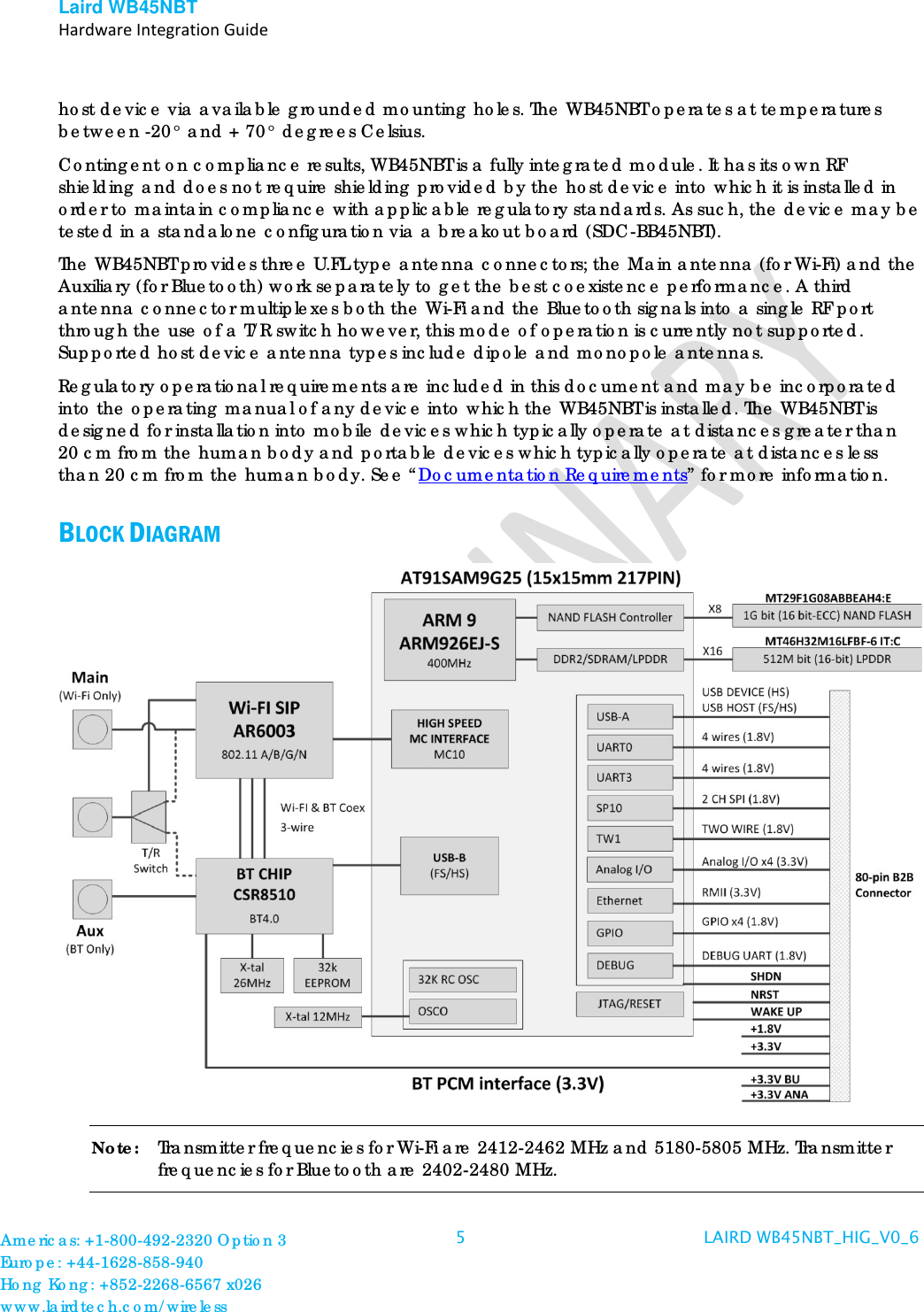
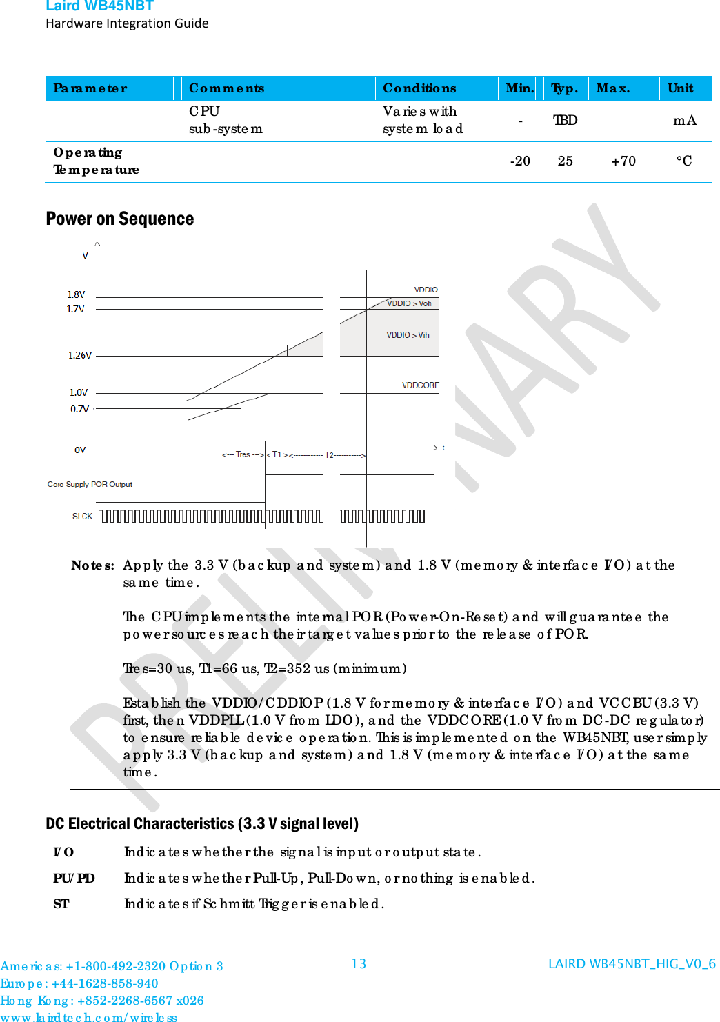
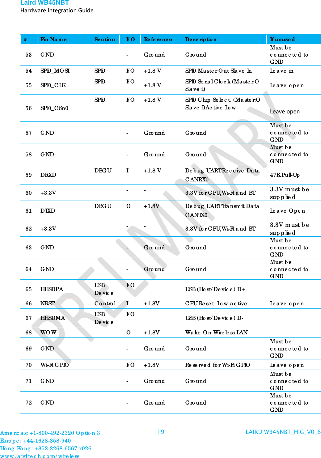
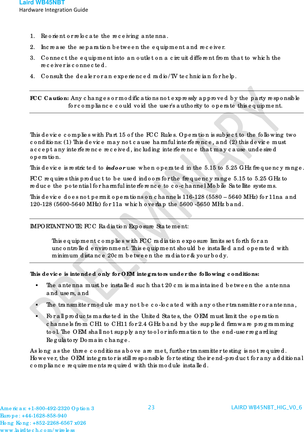
![Laird WB45NBT Hardware Integration Guide TR Tri-state Parameter Conditions Min. Typ. Max. Unit AIO[0-3] IRQ SHDN WKUP ETXEN;ETX[0-1];ERXER;ERX[0-1];EMDC;EMDIO;ECRSDV;EREF_CLK I/O;PU;ST I;PU;ST O;PU I;ST Note: PU;ST VIL Input Low-Level Voltage -0.3 - 0.8 V VIH Input High-Level Voltage 2.0 3.6 V VOL Output Low-Level Voltage 0.4 V VOH Output High-Level Voltage 2.9 V VT- Schmitt trigger Negative-going threshold Voltage 0.8 1.1 V VT+ Schmitt trigger Positive-going threshold Voltage 1.6 2.0 V VHYS Schmitt trigger Hysteresis 0.5 0.75 V RPULLUP Pull-up/Pull-down Resistance 40 75 190 KΩ IO Output Current 8 mA Americas: +1-800-492-2320 Option 3 Europe: +44-1628-858-940 Hong Kong: +852-2268-6567 x026 www.lairdtech.com/wireless 14 LAIRD WB45NBT_HIG_V0_6](https://usermanual.wiki/Laird-Technologies/WB45NBT.Users-Manual/User-Guide-2052253-Page-14.png)
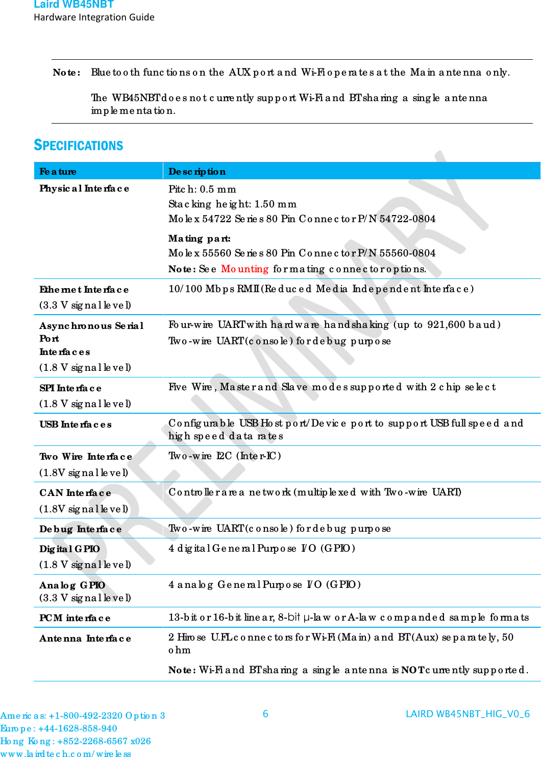
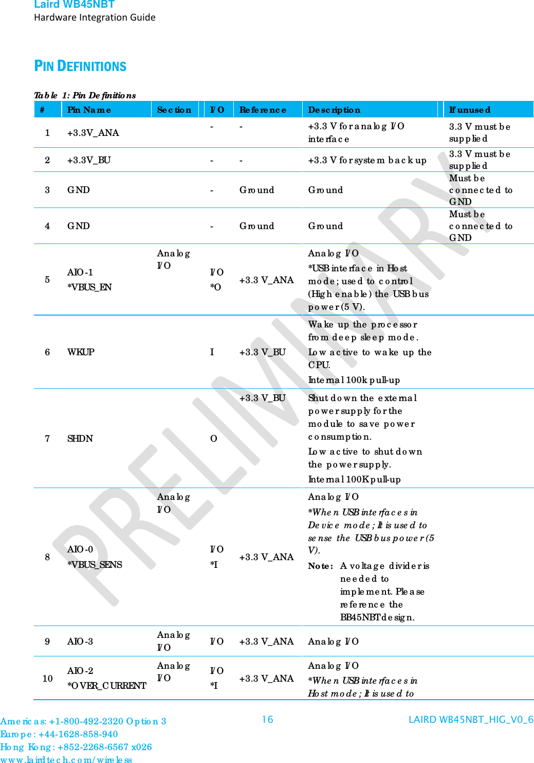
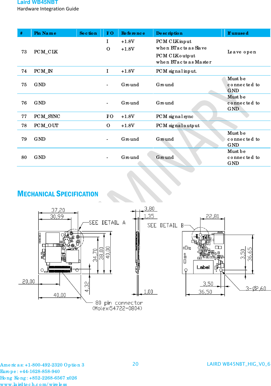
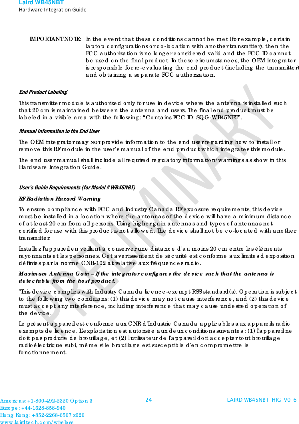
![Laird WB45NBT Hardware Integration Guide DC Electrical Characteristics (1.8 V signal level) I/O Indicates whether the signal is input or output state. PU/PD Indicates whether Pull-Up, Pull-Down or nothing is enabled. ST Indicates if Schmitt Trigger is enabled. TR Tri-state Parameter Conditions Min. Typ. Max. Unit GPIO[0-3] TWCK1;TWD1 WOW WIFI_GPIO URTS0;UCTS0;URXD0;UTXD0;URTS3;UCTS3;URXD3;UTXD3 DTXD;DRXD PCM_CLK;PCM_SYNC;PCM_OUT;PCM_IN I/O;PU;ST Note: PU;ST O I/O Notes: PU;ST PU;ST PD;TR VIL Input Low-Level Voltage -0.3 - 0.54 V VIH Input High-Level Voltage 1.26 2.1 V VOL Output Low-Level Voltage 0.4 V VOH Output High-Level Voltage 1.4 V VT- Schmitt trigger Negative-going threshold Voltage 0.54 V VT+ Schmitt trigger Positive-going threshold Voltage 0.54 V VHYS Schmitt trigger Hysteresis 0.28 0.6 V RPULLUP Pull-up/Pull-down Resistance 240 1000 KΩ IO Output Current 2 mA Note: We recommend that 1.8 V signal I/O pins should not be used to drive the external circuit directly due to its weak drive capability. A buffer/driver should be used in such applications. Americas: +1-800-492-2320 Option 3 Europe: +44-1628-858-940 Hong Kong: +852-2268-6567 x026 www.lairdtech.com/wireless 15 LAIRD WB45NBT_HIG_V0_6](https://usermanual.wiki/Laird-Technologies/WB45NBT.Users-Manual/User-Guide-2052253-Page-15.png)
![Laird WB45NBT Hardware Integration Guide EN 300 328 V1.7.1: (2006-10) Electromagnetic compatibility and Radio spectrum Matters (ERM); Wideband Transmission systems; Data transmission equipment operating in the 2,4 GHz ISM band and using spread spectrum modulation techniques; Harmonized EN covering essential requirements under article 3.2 of the R&TTE Directive EN 301 489-1 V1.6.1: (2005-09) Electromagnetic compatibility and Radio Spectrum Matters (ERM); ElectroMagnetic Compatibility (EMC) standard for radio equipment and services; Part 1: Common technical requirements EN 301 489-17 V1.2.1 (2002-08) Electromagnetic compatibility and Radio spectrum Matters (ERM); ElectroMagnetic Compatibility (EMC) standard for radio equipment and services; Part 17: Specific conditions for 2,4 GHz wideband transmission systems and 5 GHz high performance RLAN equipment EN 301 893 V1.5.1 (2008-12) Electromagnetic compatibility and Radio spectrum Matters (ERM); Broadband Radio Access Networks (BRAN); Specific conditions for 5 GHz high performance RLAN equipment EU 2002/95/EC (RoHS) Declaration of Compliance – EU Directive 2003/95/EC; Reduction of Hazardous Substances (RoHS) This device is a 2.4 GHz wideband transmission system (transceiver), intended for use in all EU member states and EFTA countries, except in France and Italy where restrictive use applies. In Italy the end-user should apply for a license at the national spectrum authorities in order to obtain authorization to use the device for setting up outdoor radio links and/or for supplying public access to telecommunications and/or network services. This device may not be used for setting up outdoor radio links in France and in some areas the RF output power may be limited to 10 mW EIRP in the frequency range of 2454 – 2483.5 MHz. For detailed information the end-user should contact the national spectrum authority in France. Česky [Czech] [Jméno výrobce] tímto prohlašuje, že tento [typ zařízení] je ve shodě se základními požadavky a dalšími příslušnými ustanoveními směrnice 1999/5/ES. Dansk [Danish] Undertegnede [fabrikantens navn] erklærer herved, at følgende udstyr [udstyrets typebetegnelse] overholder de væsentlige krav og øvrige relevante krav i direktiv 1999/5/EF. Deutsch [German] Hiermit erklärt [Name des Herstellers], dass sich das Gerät [Gerätetyp] in Übereinstimmung mit den grundlegenden Anforderungen und den übrigen einschlägigen Bestimmungen der Richtlinie 1999/5/EG befindet. Americas: +1-800-492-2320 Option 3 Europe: +44-1628-858-940 Hong Kong: +852-2268-6567 x026 www.lairdtech.com/wireless 27 LAIRD WB45NBT_HIG_V0_6](https://usermanual.wiki/Laird-Technologies/WB45NBT.Users-Manual/User-Guide-2052253-Page-27.png)
![Laird WB45NBT Hardware Integration Guide Eesti [Estonian] Käesolevaga kinnitab [tootja nimi = name of manufacturer] seadme [seadme tüüp = type of equipment] vastavust direktiivi 1999/5/EÜ põhinõuetele ja nimetatud direktiivist tulenevatele teistele asjakohastele sätetele. English Hereby, [name of manufacturer], declares that this [type of equipment] is in compliance with the essential requirements and other relevant provisions of Directive 1999/5/EC. Español [Spanish] Por medio de la presente [nombre del fabricante] declara que el [clase de equipo] cumple con los requisitos esenciales y cualesquiera otras disposiciones aplicables o exigibles de la Directiva 1999/5/CE. Ελληνική [Greek] ΜΕ ΤΗΝ ΠΑΡΟΥΣΑ [name of manufacturer] ΔΗΛΩΝΕΙ ΟΤΙ [type of equipment] ΣΥΜΜΟΡΦΩΝΕΤΑΙ ΠΡΟΣ ΤΙΣ ΟΥΣΙΩΔΕΙΣ ΑΠΑΙΤΗΣΕΙΣ ΚΑΙ ΤΙΣ ΛΟΙΠΕΣ ΣΧΕΤΙΚΕΣ ΔΙΑΤΑΞΕΙΣ ΤΗΣ ΟΔΗΓΙΑΣ 1999/5/ΕΚ. Français [French] Par la présente [nom du fabricant] déclare que l'appareil [type d'appareil] est conforme aux exigences essentielles et aux autres dispositions pertinentes de la directive 1999/5/CE. Italiano [Italian] Con la presente [nome del costruttore] dichiara che questo [tipo di apparecchio] è conforme ai requisiti essenziali ed alle altre disposizioni pertinenti stabilite dalla direttiva 1999/5/CE. Latviski [Latvian] Aršo[name of manufacturer / izgatavotājanosaukums] deklarē, ka[type of equipment / iekārtas tips]atbilstDirektīvas 1999/5/EK būtiskajāmprasībām un citiemar to saistītajiemnoteikumiem. Lietuvių [Lithuanian] Šiuo [manufacturer name] deklaruoja, kad šis [equipment type] atitinka esminius reikalavimus ir kitas 1999/5/EB Direktyvos nuostatas. Nederlands [Dutch] Hierbij verklaart [naam van de fabrikant] dat het toestel [type van toestel] in overeenstemming is met de essentiële eisen en de andere relevante bepalingen van richtlijn 1999/5/EG. Malti [Maltese] Hawnhekk, [isem tal-manifattur], jiddikjara li dan [il-mudel tal-prodott] jikkonforma mal-ħtiġijiet essenzjali u ma provvedimenti oħrajn relevanti li hemm fid-Dirrettiva 1999/5/EC. Magyar [Hungarian] Alulírott, [gyártó neve] nyilatkozom, hogy a [... típus]megfelel a vonatkozó alapvetõ követelményeknek és az 1999/5/EC irányelv egyéb elõírásainak. Polski [Polish] Niniejszym [nazwa producenta] oświadcza, że [nazwa wyrobu] jest zgodny z zasadniczymi wymogami oraz pozostałymi stosownymi postanowieniami Dyrektywy 1999/5/EC. Português [Portuguese] [Nome do fabricante] declara que este [tipo de equipamento] está conforme com os requisitos essenciais e outras disposições da Directiva Americas: +1-800-492-2320 Option 3 Europe: +44-1628-858-940 Hong Kong: +852-2268-6567 x026 www.lairdtech.com/wireless 28 LAIRD WB45NBT_HIG_V0_6](https://usermanual.wiki/Laird-Technologies/WB45NBT.Users-Manual/User-Guide-2052253-Page-28.png)
![Laird WB45NBT Hardware Integration Guide 1999/5/CE. Slovensko [Slovenian] [Ime proizvajalca] izjavlja, da je ta [tip opreme] v skladu z bistvenimi zahtevami in ostalimi relevantnimi določili direktive 1999/5/ES. Slovensky [Slovak] [Menovýrobcu] týmtovyhlasuje, že [typzariadenia] spĺňazákladnépožiadavky a všetkypríslušnéustanovenia Smernice 1999/5/ES. Suomi [Finnish] [Valmistaja = manufacturer] vakuuttaa täten että [type of equipment = laitteen tyyppimerkintä] tyyppinen laite on direktiivin 1999/5/EY oleellisten vaatimusten ja sitä koskevien direktiivin muiden ehtojen mukainen. Svenska [Swedish] Härmed intygar [företag] att denna [utrustningstyp] står I överensstämmelse med de väsentliga egenskapskrav och övriga relevanta bestämmelser som framgår av direktiv 1999/5/EG. Americas: +1-800-492-2320 Option 3 Europe: +44-1628-858-940 Hong Kong: +852-2268-6567 x026 www.lairdtech.com/wireless 29 LAIRD WB45NBT_HIG_V0_6](https://usermanual.wiki/Laird-Technologies/WB45NBT.Users-Manual/User-Guide-2052253-Page-29.png)