Landis Gyr Technology CONCS4B5 Series-4 Concentrator, BLT5 User Manual 12 0408 Exhibit Cover
Landis+Gyr Technology, Inc. Series-4 Concentrator, BLT5 12 0408 Exhibit Cover
UserManual.wiki
>
Landis Gyr Technology
>
CONCS4B5 User Manual
Manual
Navigation menu
Upload a User Manual
Namespaces
Wiki Guide
HTML
PDF
Info
Views
User Manual
Discussion / Help
Navigation


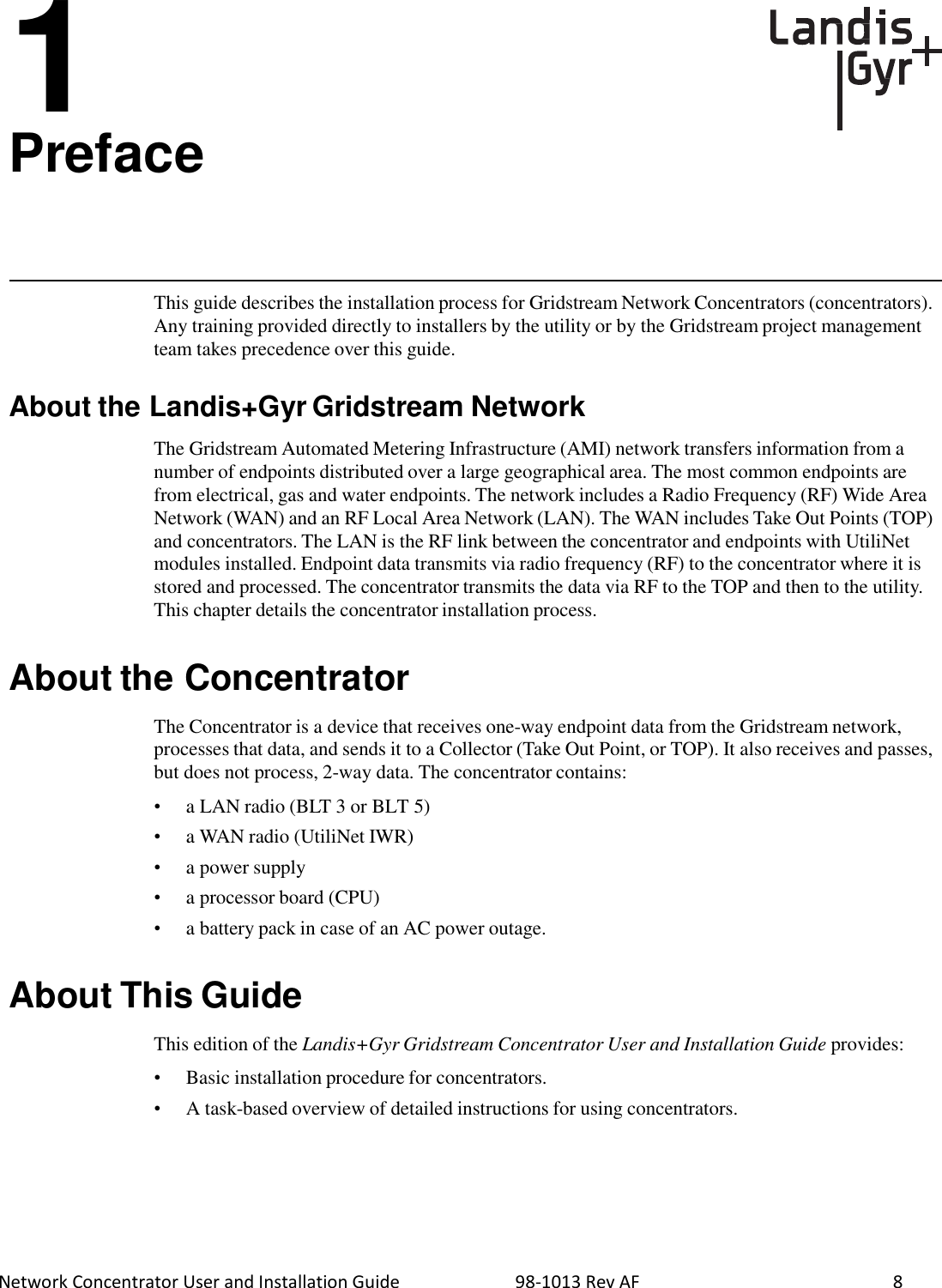
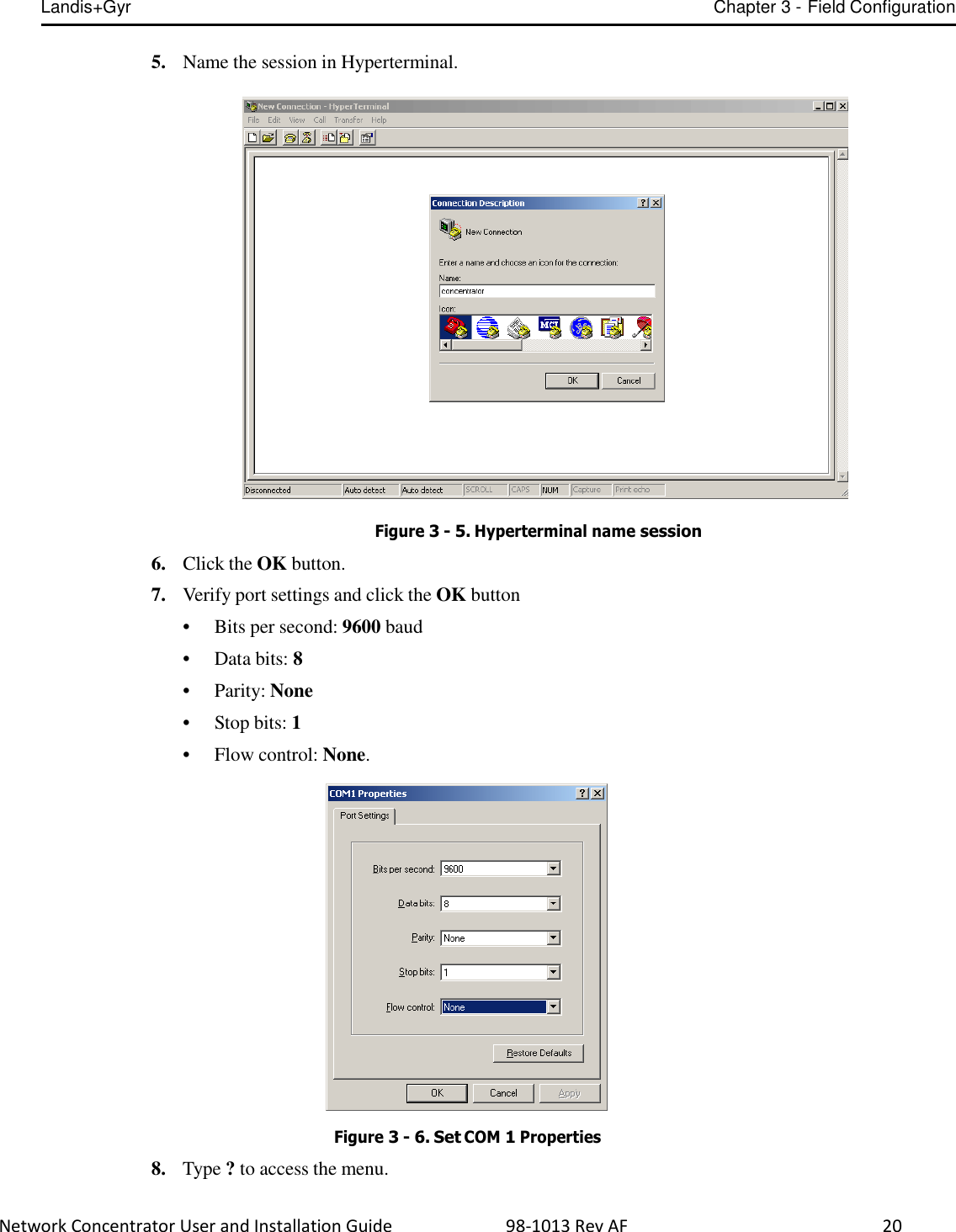
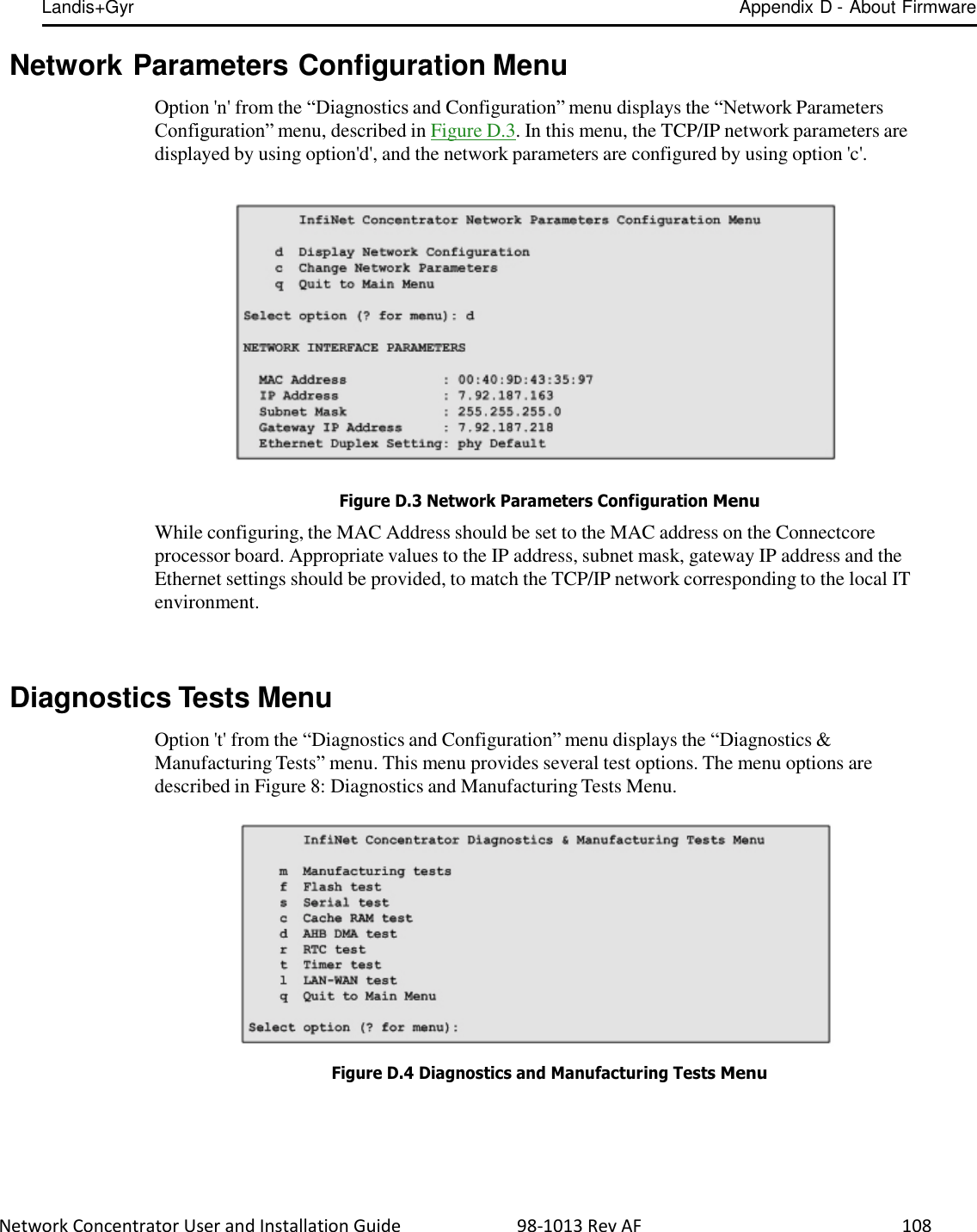
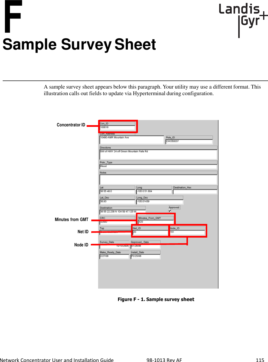
![Landis+Gyr Chapter 3 - Field Configuration Network Concentrator User and Installation Guide 98-1013 Rev AF 21 9. Type c for configuration. Figure 3 - 7. Type “c” For Configuration 10. Type s for set specific items. Figure 3 - 8. Type “s” to Set Specific Items 11. Reset values by typing the letter in Hyperterminal corresponding to the item, then updating the value. For more information, see Sample Survey Sheet. Update the following items: A. [d]*Gateway MCC DMS Net Address [1..4294967039;default=4294967038]: 100051 Input the assigned Concentrator ID here. B. [e]*Gateway MCC DMS node address (normally 1) C. [1..65534;default=65534]: 1 This value is always 1. D. [f]+Log manager's (and CTS's) DMS Net Address [1..4294967039;default=4294967039]: 20 Input the assigned Net ID.](https://usermanual.wiki/Landis-Gyr-Technology/CONCS4B5/User-Guide-2014067-Page-23.png)
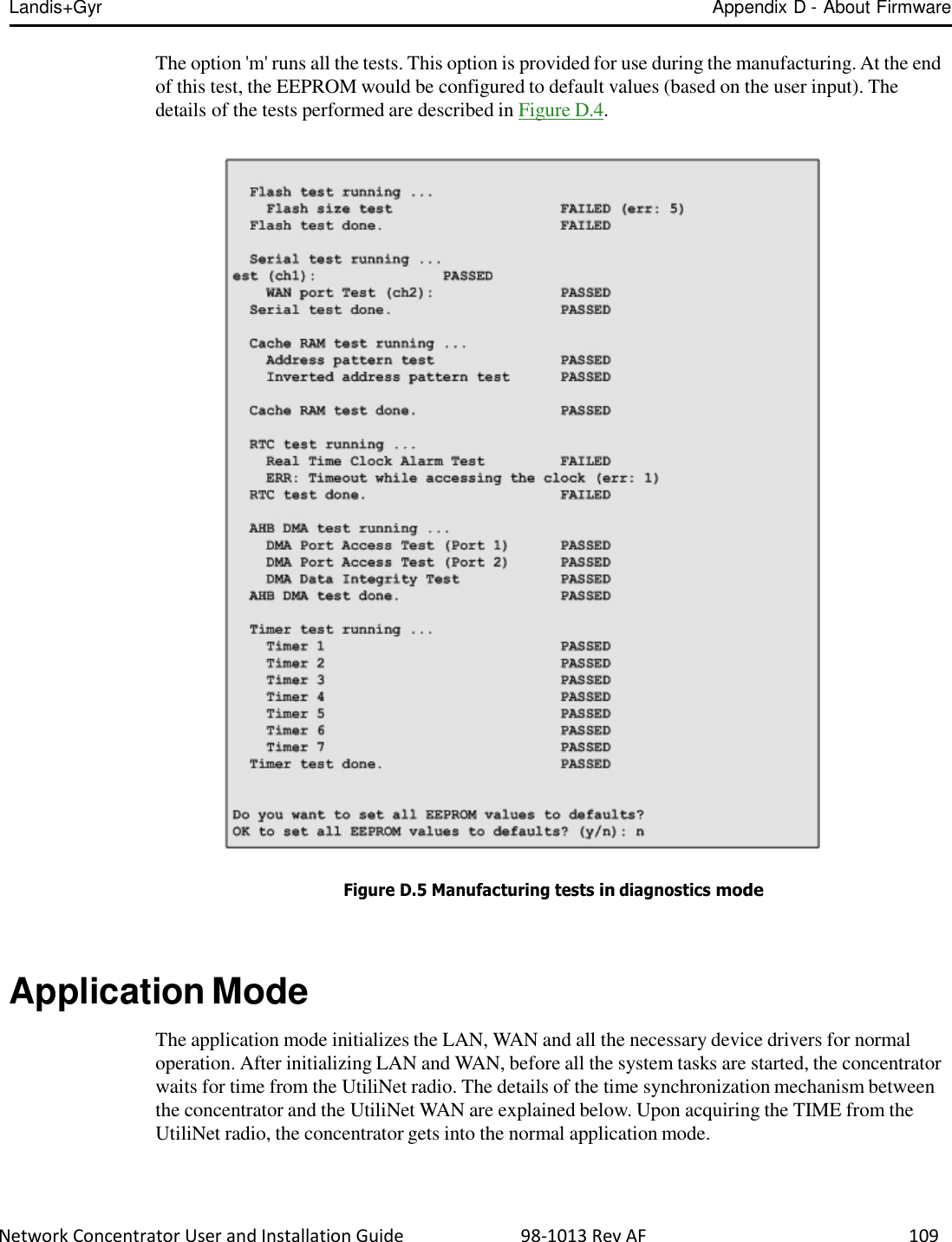
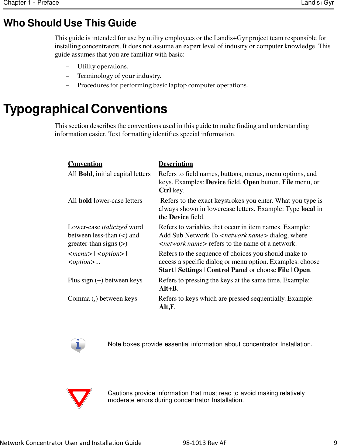
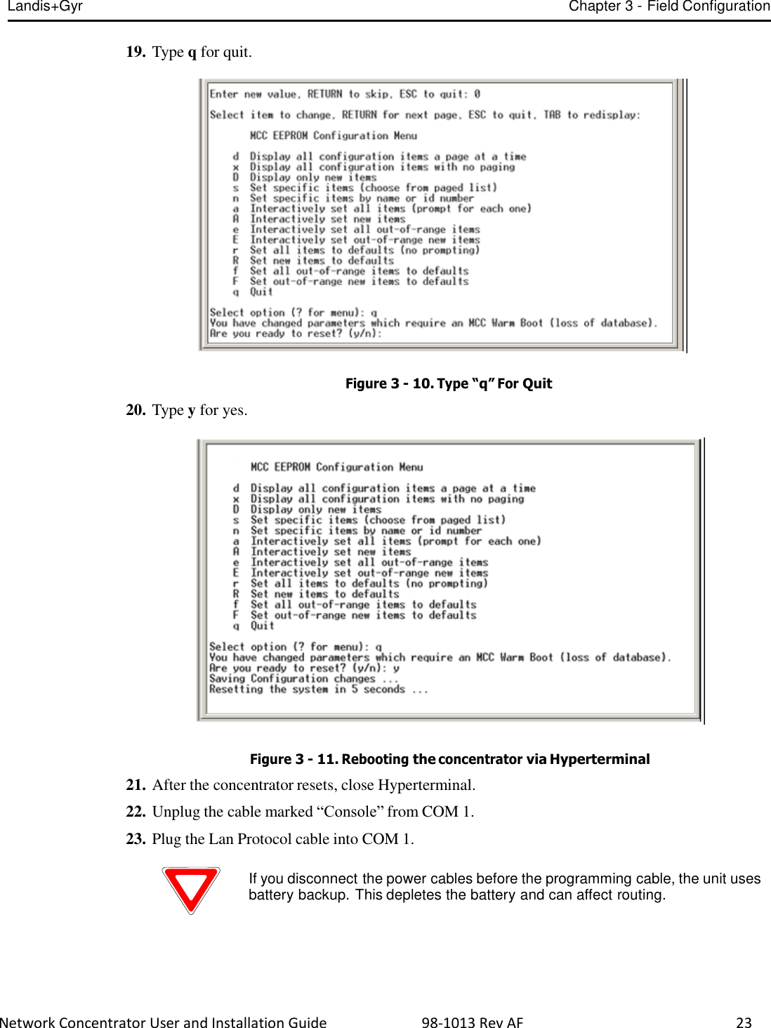
![Landis+Gyr Chapter 3 - Field Configuration Network Concentrator User and Installation Guide 98-1013 Rev AF 22 E. [g]+Log manager's (and CTS's) DMS node address [1..65534;default=65534]: 152 Input the assigned Node ID. F. [h]+Event manager's DMS Net Address [1..4294967039;default=4294967039]: 20 Input the assigned Net ID again. G. [i]+Event manager's DMS node address [1..65534;default=65534]: 152 Input the assigned Node ID again. H. [m]*Minutes from GMT (0=GMT, 480=PST) [positive increments of 60] [- 720..720;default=480]: 420 Input the minutes from GMT. I. [n]*Daylight savings type (0=none, 1=USA, 7=UK) [0..7;default=1]: 1 This value is always 1. 12. After you change the value, press the TAB key to refresh the page. 13. Press the Enter key to go to the next page. 14. Update the following field: A. [e]+Lan Tx address for this MCC (0 = no Tx) [default=0]: 0 Always start with the number 400 (unless the concentrator address is 5 digits, then start with 4000), then append the concentrator ID. For example, if the concentrator ID is 100016, then the Lan Tx address is 400100016. 15. Press the Enter key until you see a list of Network Filter configuration items. . Figure 3 - 9. Type “0” For Disable 16. Type the letter J for Network Filter: Disable/Enable option. 17. Type 0 to disable network filtering, and then press [Enter] 18. Press the Escape key.](https://usermanual.wiki/Landis-Gyr-Technology/CONCS4B5/User-Guide-2014067-Page-24.png)
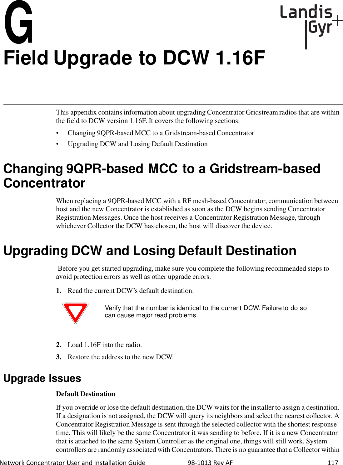
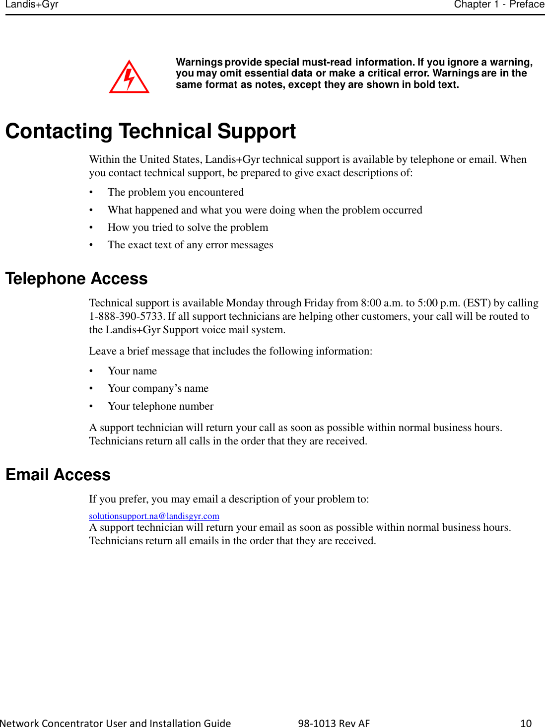
![Landis+Gyr Chapter 3 - Field Configuration Network Concentrator User and Installation Guide 98-1013 Rev AF 25 3. Use the command rcautil xxxx 1 to log into the concentrator with id xxxx. Example: rcautil 5002 1 Figure 3 - 14. Login to concentrator 4. After the screen displays “Remote console device CONNECTED”, press [Enter]. Figure 3 - 15. Open console menu remotely 5. Type the letter c. The EEPROM configuration menu displays.](https://usermanual.wiki/Landis-Gyr-Technology/CONCS4B5/User-Guide-2014067-Page-27.png)

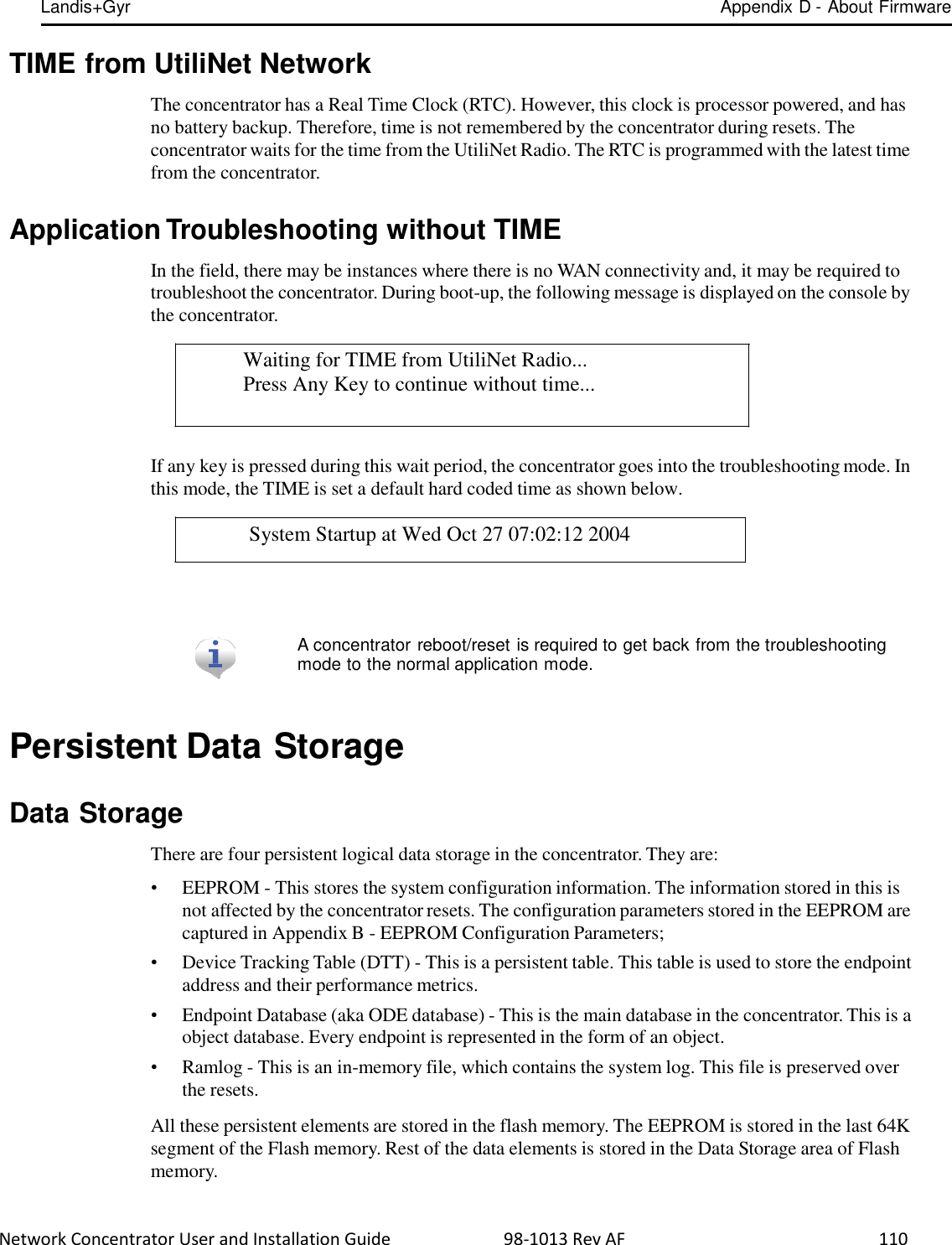
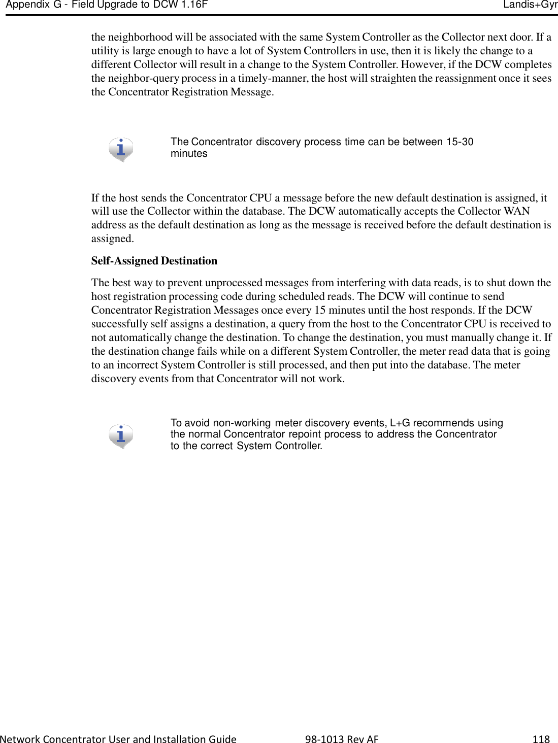
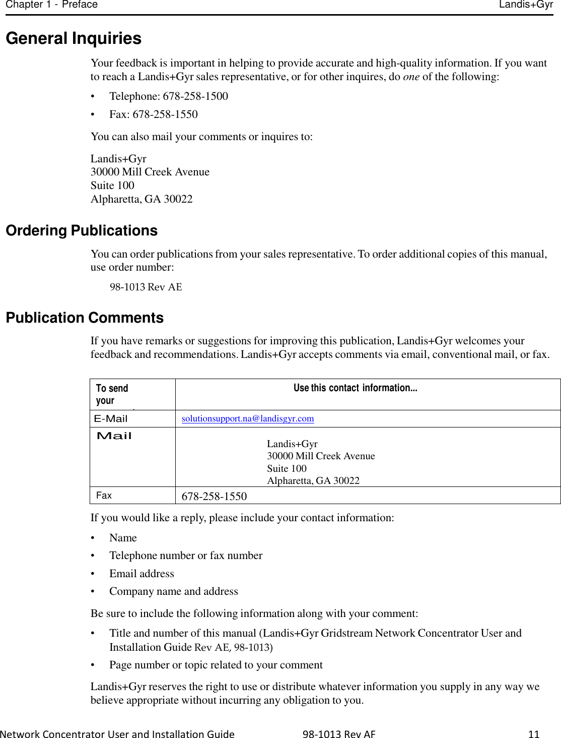
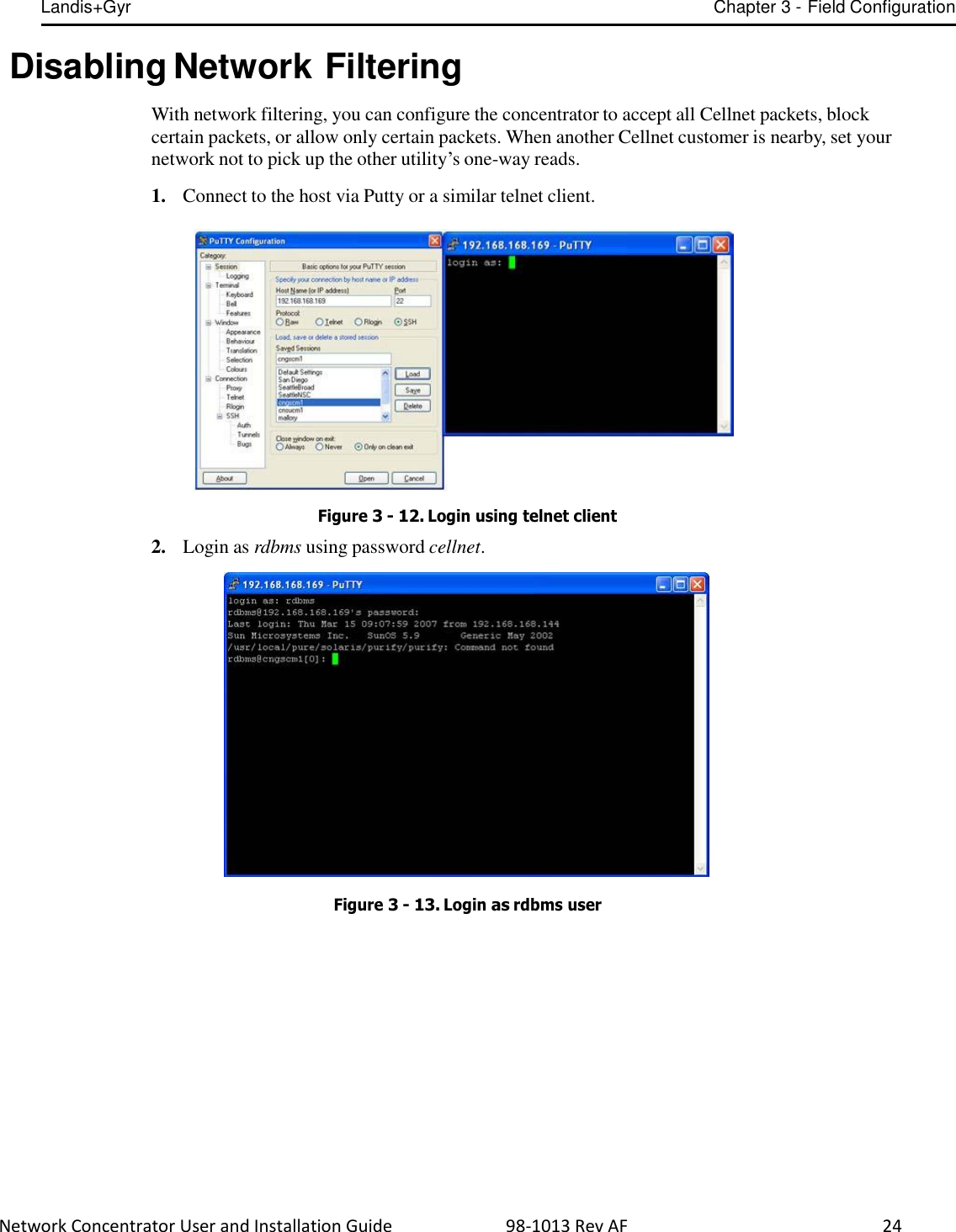
![Landis+Gyr Chapter 3 - Field Configuration Network Concentrator User and Installation Guide 98-1013 Rev AF 27 6. Type the letter n. The system prompts for a name. Figure 3 - 17. Name prompt 7. Type 81 to access the network filtering menu and press [Enter]. Figure 3 - 18. Type 81 8. The default network filtering value is 1.To disable network filtering, type 0 and press [Enter] Figure 3 - 19. Network Filtering value](https://usermanual.wiki/Landis-Gyr-Technology/CONCS4B5/User-Guide-2014067-Page-29.png)
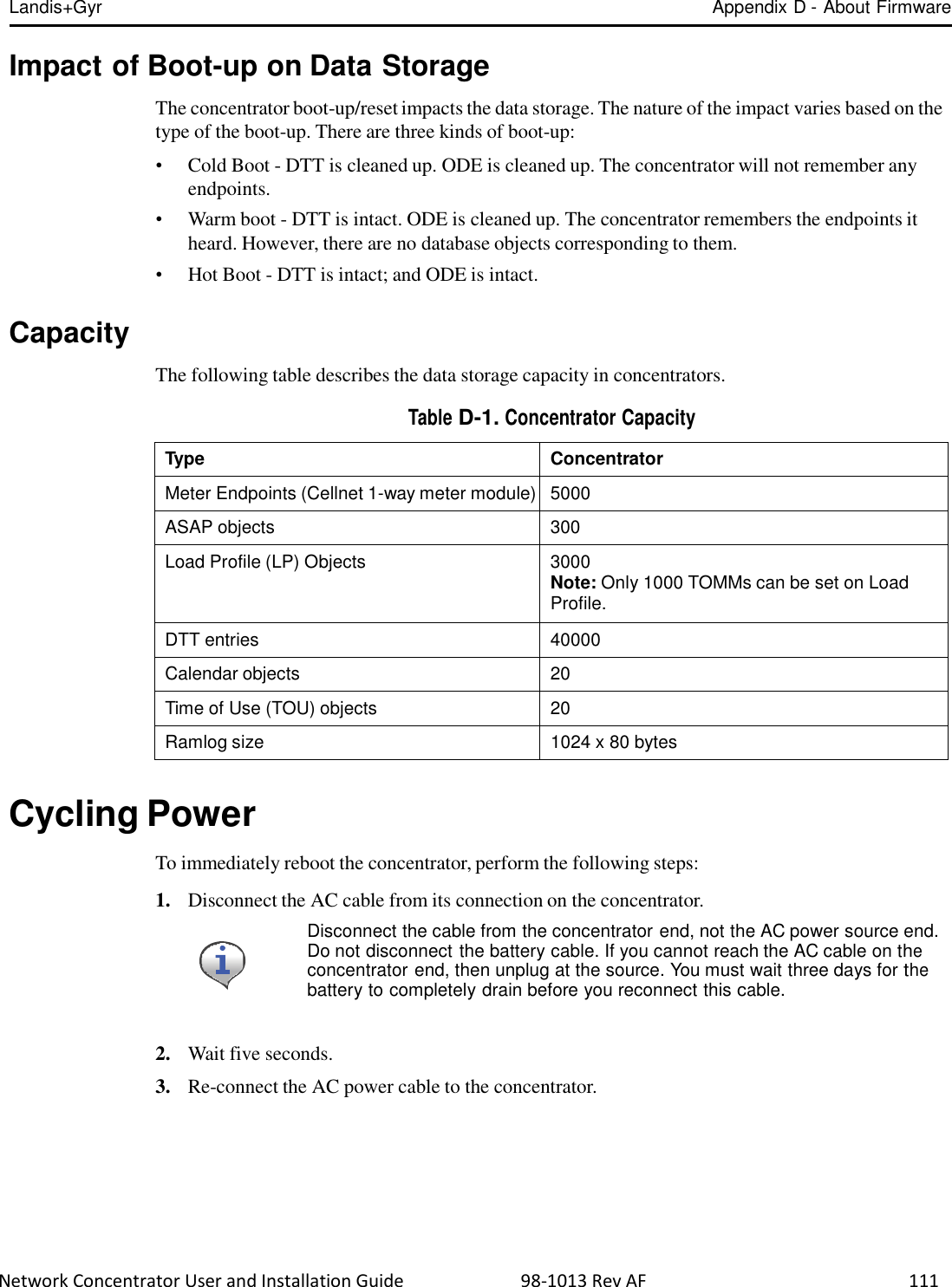
![Landis+Gyr Chapter 3 - Field Configuration Network Concentrator User and Installation Guide 98-1013 Rev AF 28 9. Type [Esc]. The EEPROM configuration menu re-displays. Figure 3 - 20. Return to EEPROM menu 10. Type the letter q. The system prompts you to hot boot the concentrator. Figure 3 - 21. Hot boot prompt 11. To save changes, type y. The hot boot begins. Figure 3 - 22. Hot boot](https://usermanual.wiki/Landis-Gyr-Technology/CONCS4B5/User-Guide-2014067-Page-30.png)

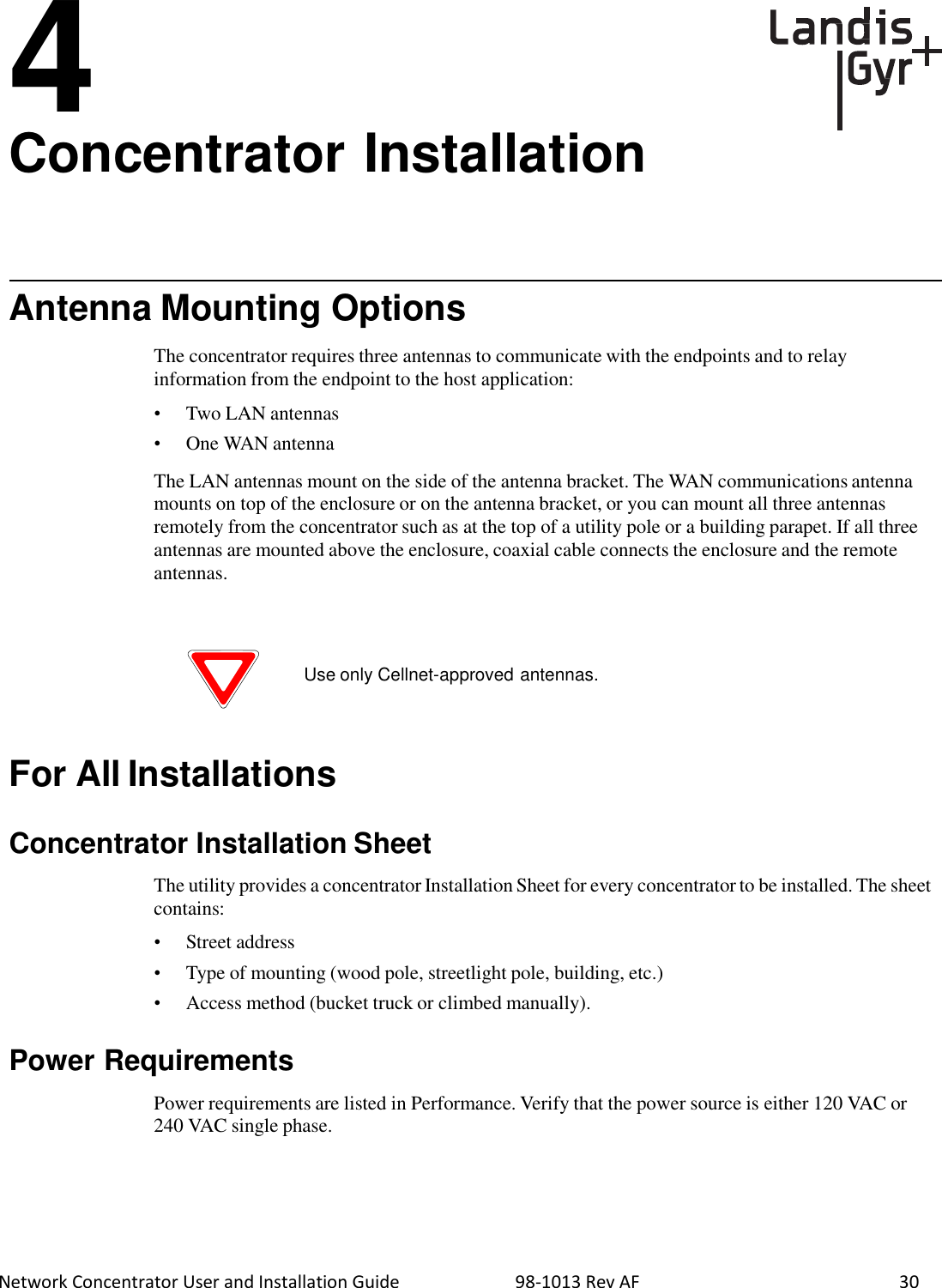
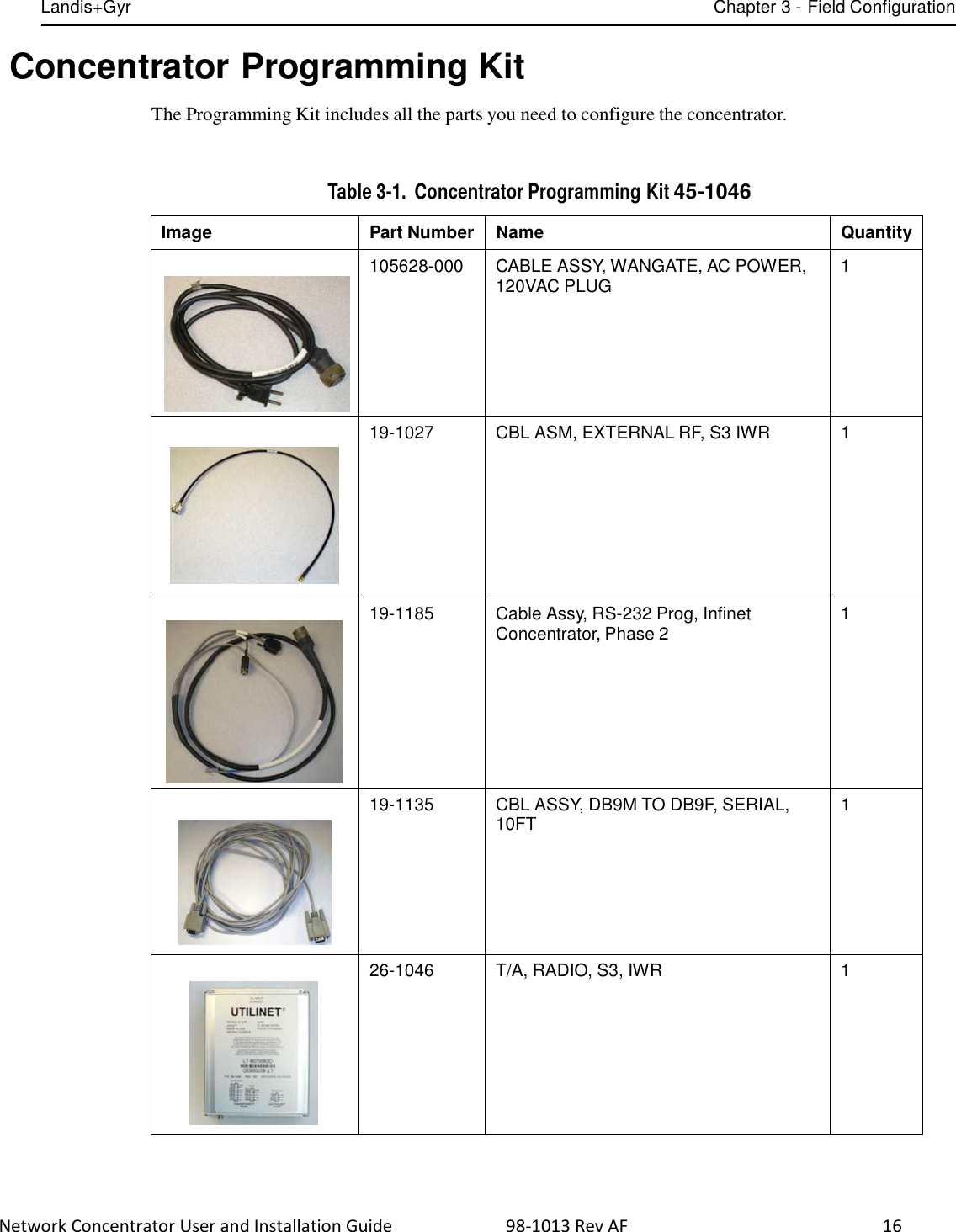
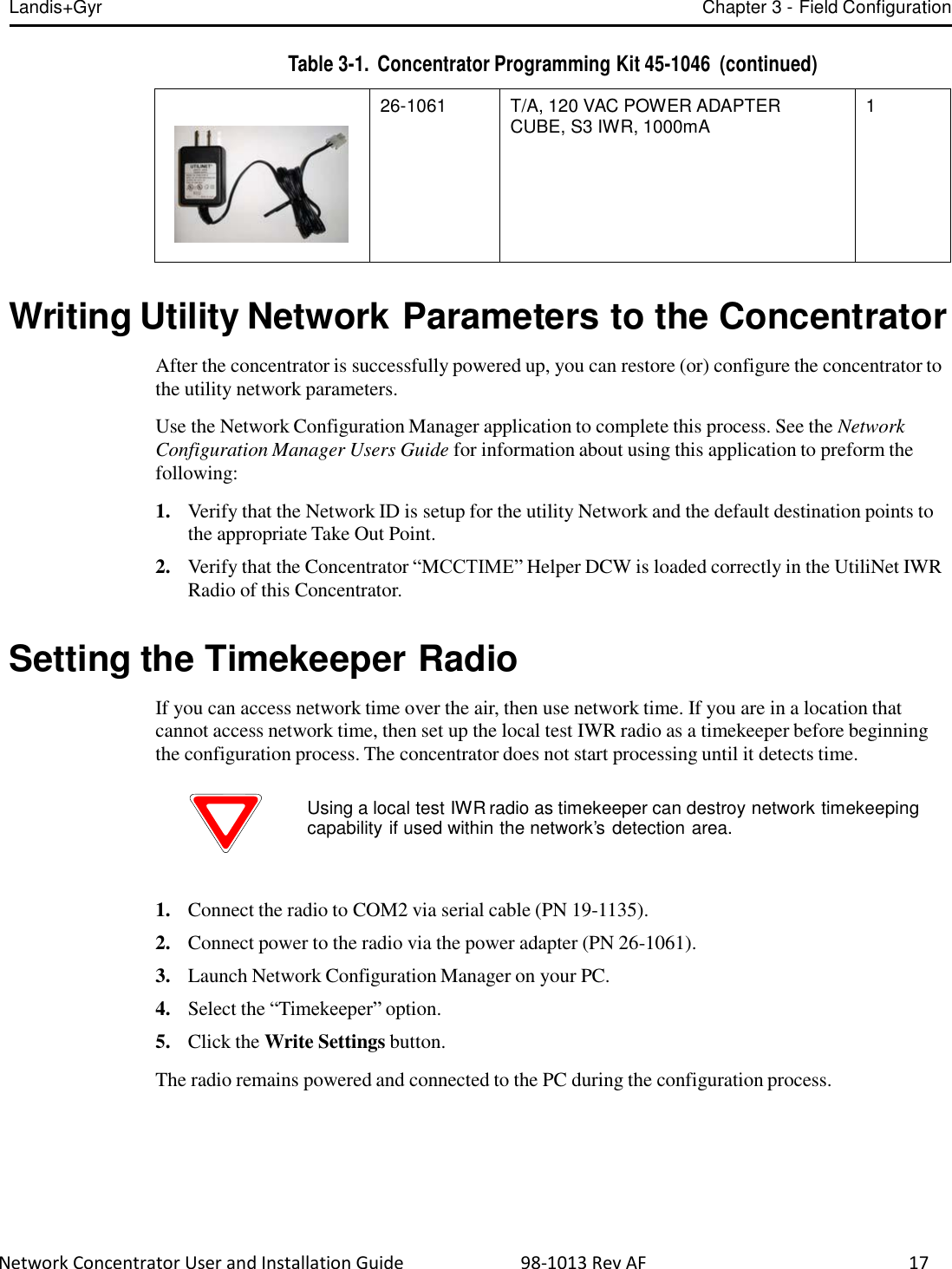
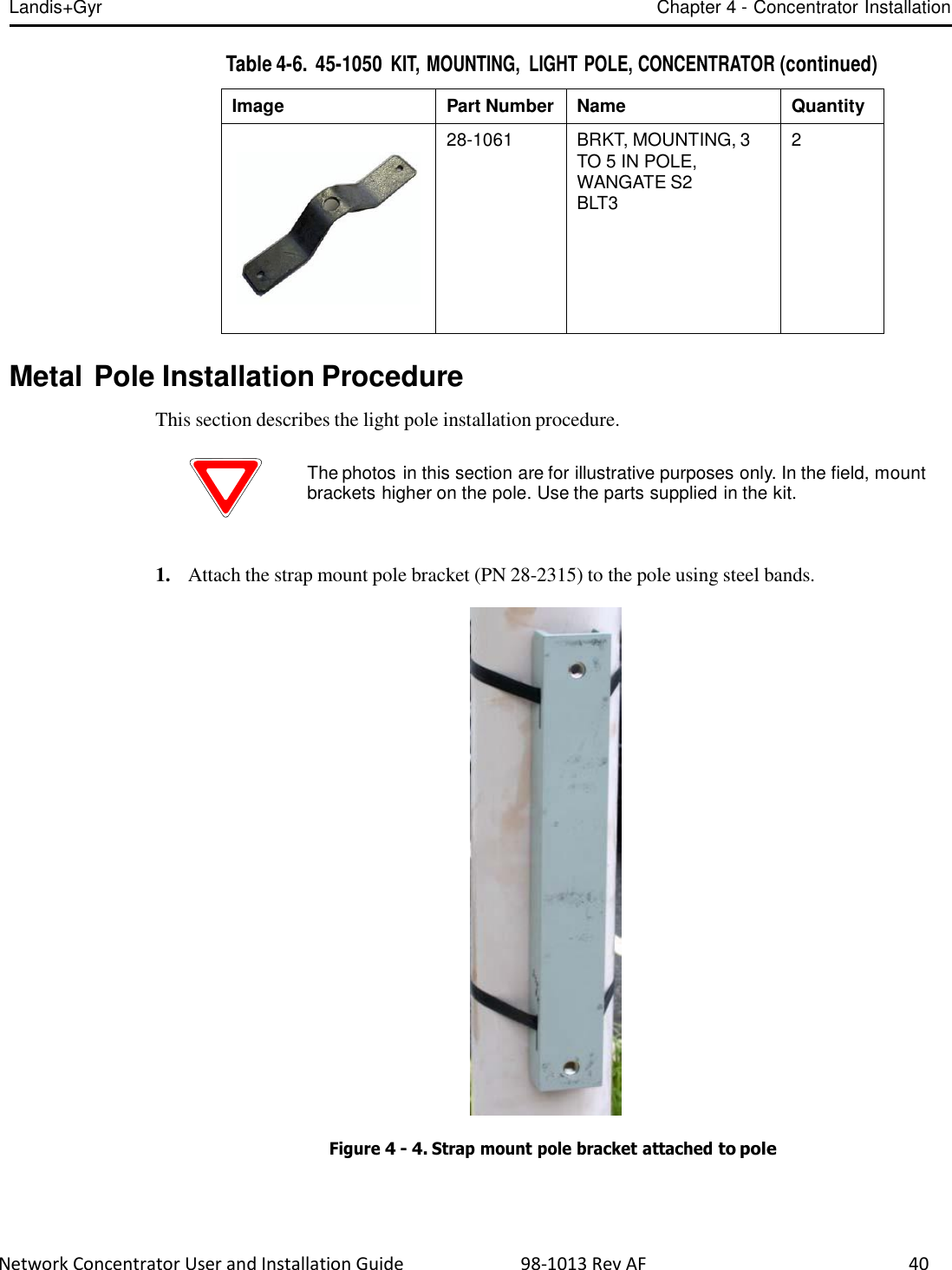
![Landis+Gyr Chapter 4 - Concentrator Installation Network Concentrator User and Installation Guide 98-1013 Rev AF 32 Kit Part Numbers Different kinds of installs may require different mounting and install kits. The following table contains a list of part numbers (PN) by install type. This document details each kit in the appropriate install description. Table 4-2. Mounting and Programming Kits Kit Number Wood Pole Install Light Pole Horizontal Mount Install Metal Pole Vertical Mount Install Mounting Kit PN 45-1048 x Mounting Kit PN 45-1050, 8” rod x Mounting Kit PN: 45-1049 x Mounting Kit PN: 45-1055, 12” rod x Programming Kit PN 45-1046 x x x For information about installation types not listed here, contact Landis+Gyr Customer Operations at ëçäìíáçåëìééçêíKå~]ä~åÇáëÖóêKÅçã.](https://usermanual.wiki/Landis-Gyr-Technology/CONCS4B5/User-Guide-2014067-Page-34.png)

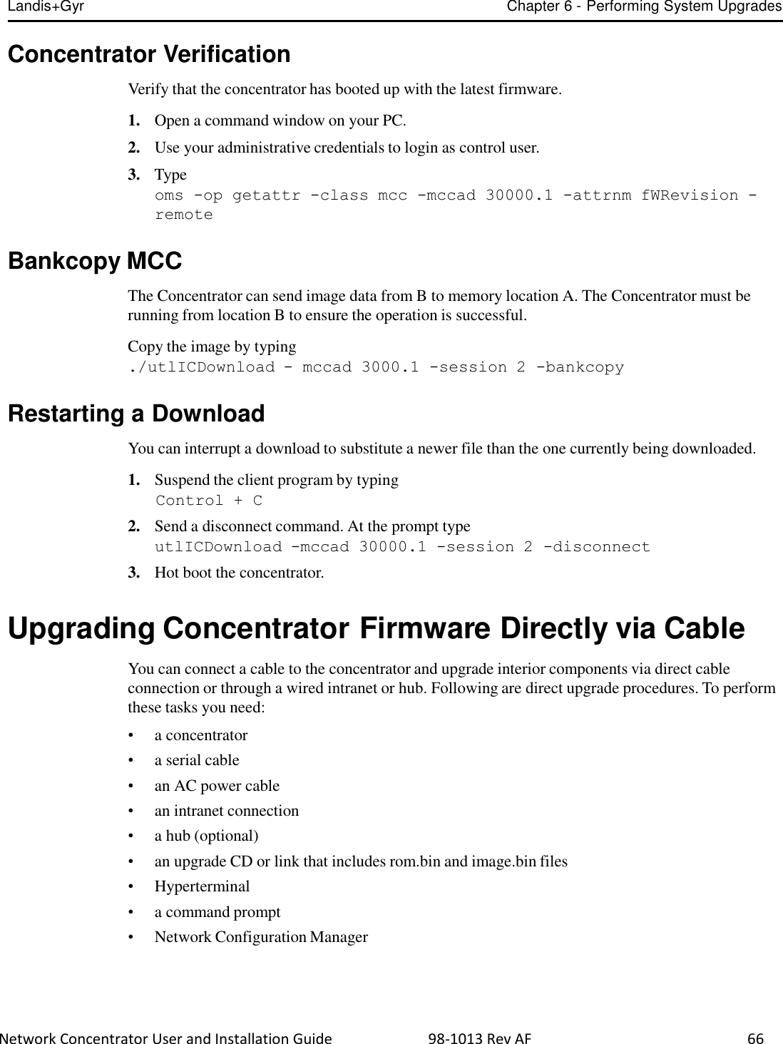
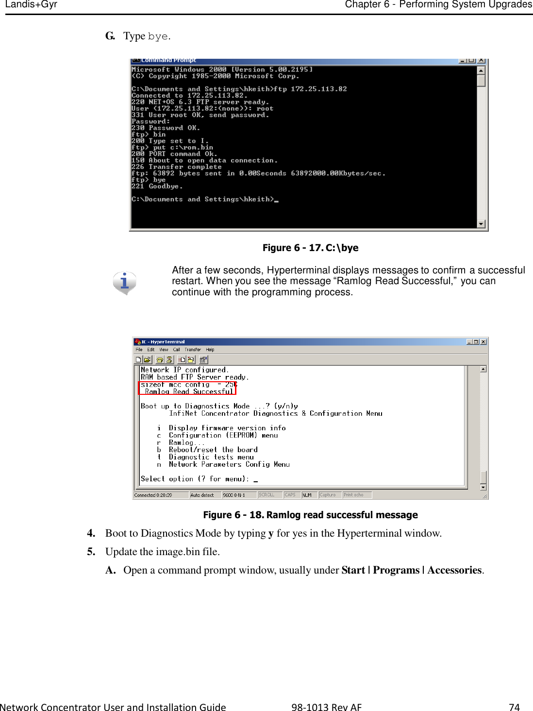
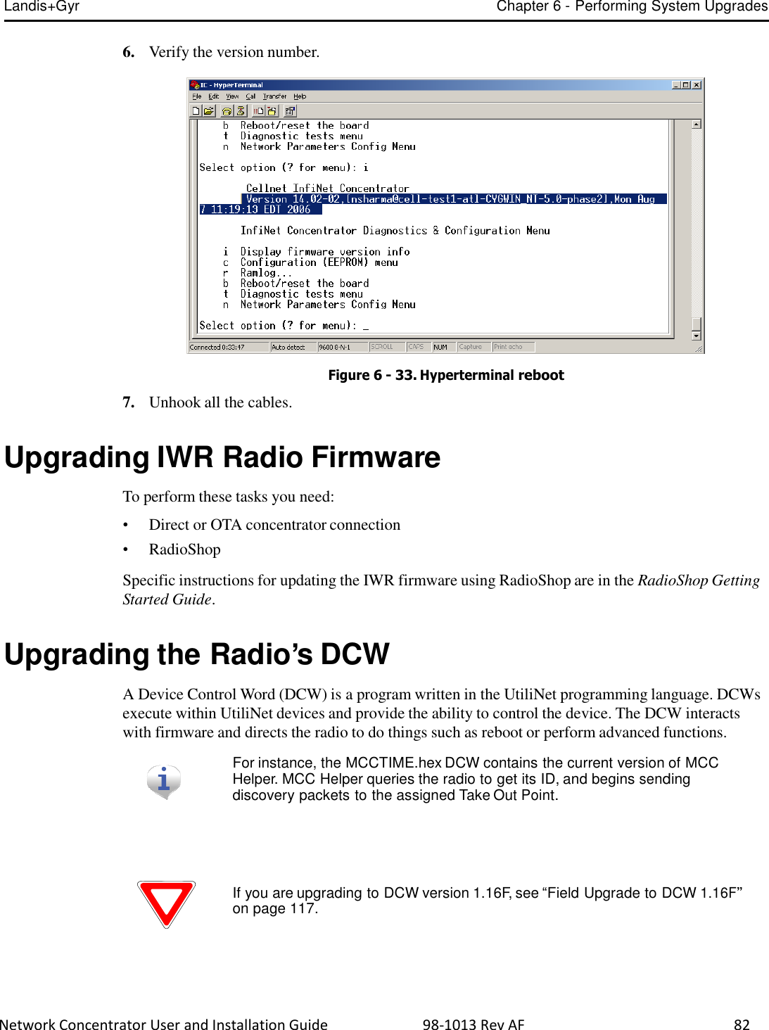
![Network Concentrator User and Installation Guide 98-1013 Rev AF 60 6 Performing System Upgrades What Are System Upgrades? There are three kinds of upgrades you can perform on a concentrator: • The concentrator firmware • The IWR radio firmware • The IWR radio DCW. Accessing a Concentrator for Programming There are two ways to access a concentrator for upgrading: • Over the air • Directly via cable (About Programming and Diagnostic Cables, for more information). Upgrading a Concentrator Over the Air (OTA) You can remotely download firmware to the concentrator via a command window from your PC. You must have control-level user access to the host to perform this procedure. About the Image File Landis+Gyr Customer Operations manages upgrades to firmware. Landis+Gyr notifies you when there is a new release of firmware and makes the file available. To upgrade firmware, load the concentrator with a new “image.bin” file. Contact Customer Operations at ëçäìíáçåëìééçêíKå~]ä~åÇáëÖóêKÅçã for more information or to obtain the latest version of the firmware. The download application utility runs on the host backend via a process called Live System update (LSU). The host connects over the air (OTA) to the concentrator. The host automatically: 1. Sends the new firmware information to the concentrator. 2. Polls the concentrator to verify that the download is complete. 3. Disconnects when the download is complete.](https://usermanual.wiki/Landis-Gyr-Technology/CONCS4B5/User-Guide-2014067-Page-61.png)
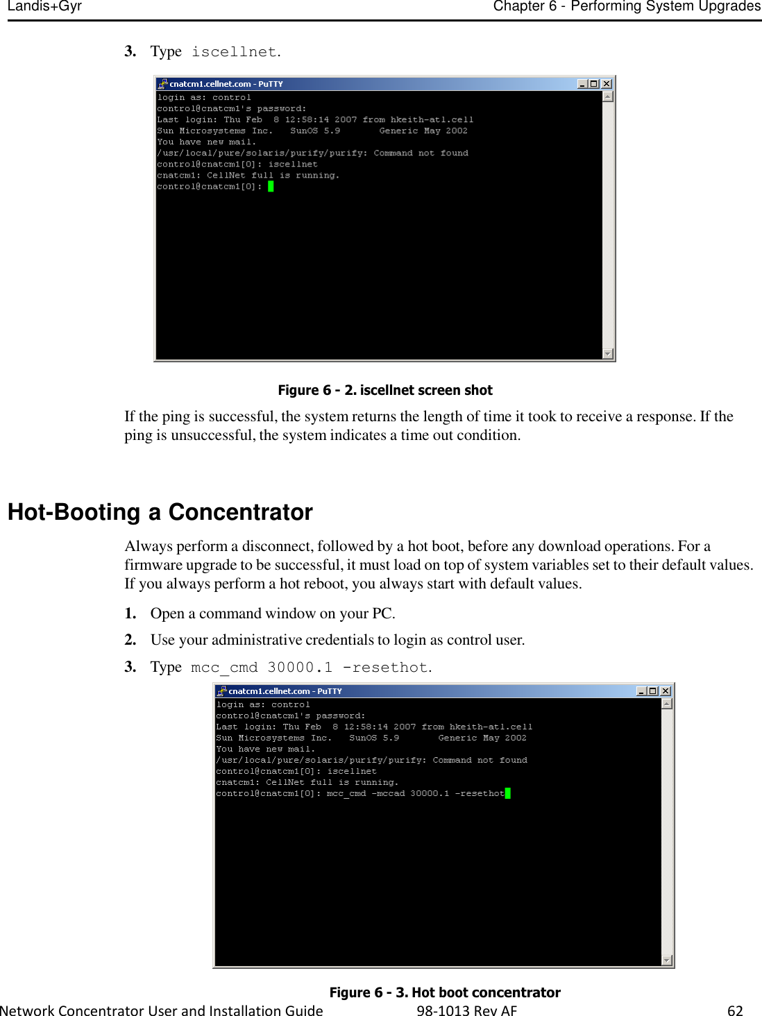
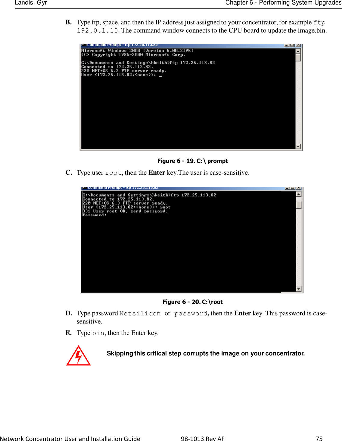
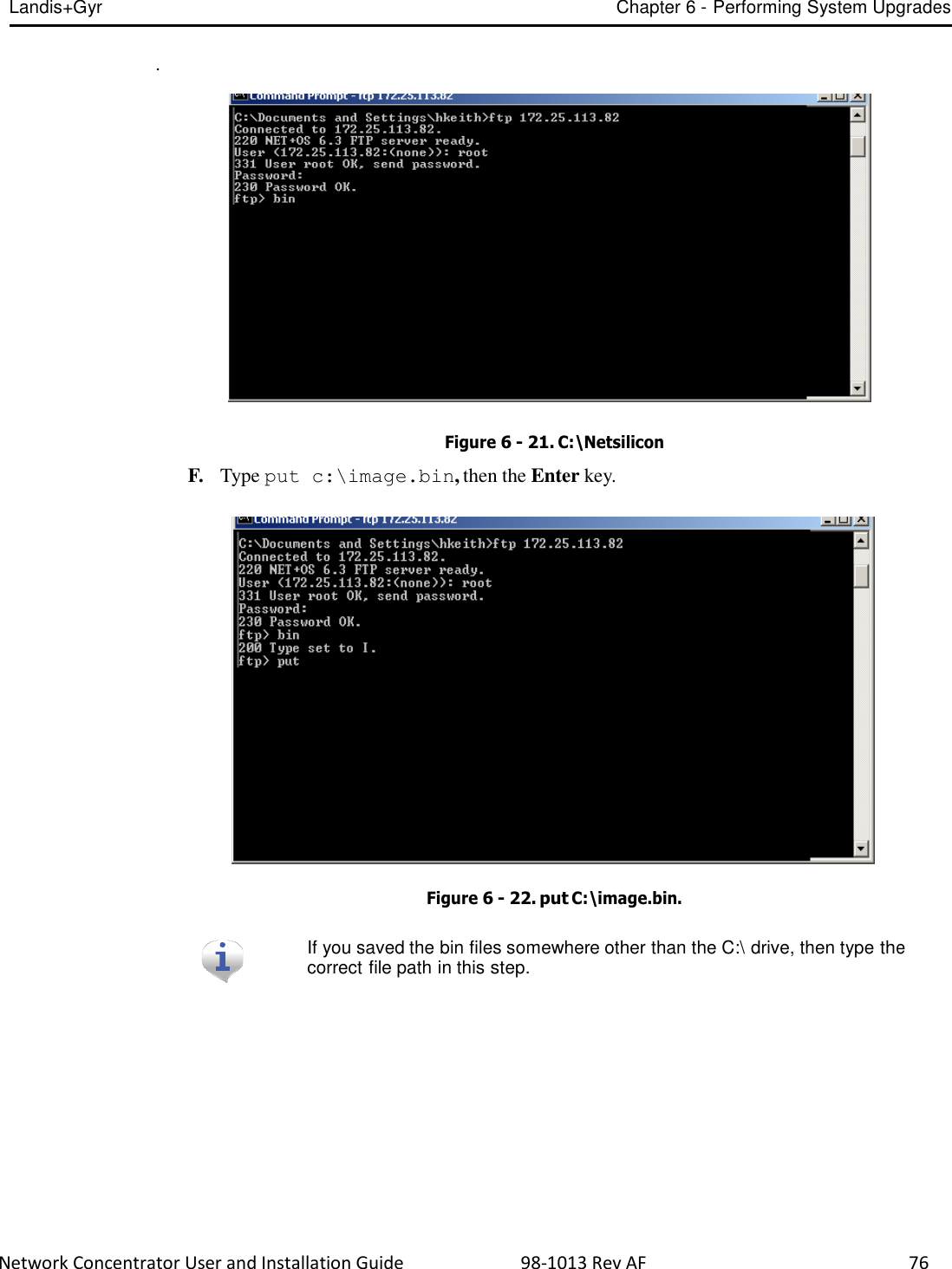
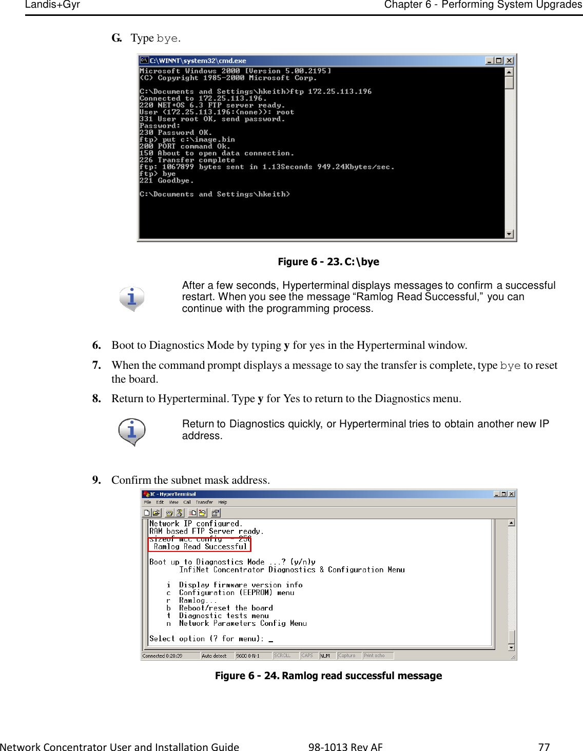
![Landis+Gyr Chapter 6 - Performing System Upgrades Network Concentrator User and Installation Guide 98-1013 Rev AF 61 Verifying the Concentrator and the Host Before sending large amounts of data over the network, verify communication with the concentrator. Also verify that the Cellnet host is up and running. Ping the concentrator via command line rtrping. Concentrator addresses used in the following instructions are samples only. Obtain your utility’s concentrator addresses from Customer Operations at ëçäìíáçåëìééçêíKå~]ä~åÇáëÖóêKÅçã. Pinging from the Command Line You need to know the concentrator’s network ID before performing this task. 1. Open a command window on your PC. 2. Use your administrative credentials to login as control user. 3. Type rtrping [concentrator ID]. Figure 6 - 1. rtrping screen shot If the ping is successful, the system returns the length of time it took to receive a response. If the ping is unsuccessful, the system indicates a time out condition. Verifying Host Operations Verify that the Cellnet system is running. 1. Open a command window on your PC. 2. Use your administrative credentials to login as control user.](https://usermanual.wiki/Landis-Gyr-Technology/CONCS4B5/User-Guide-2014067-Page-62.png)
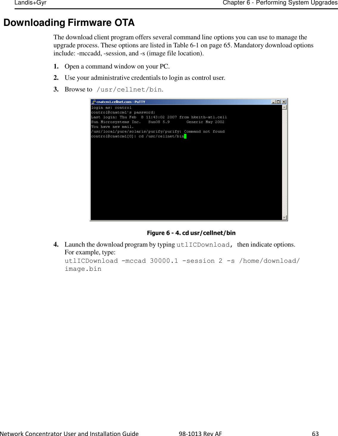
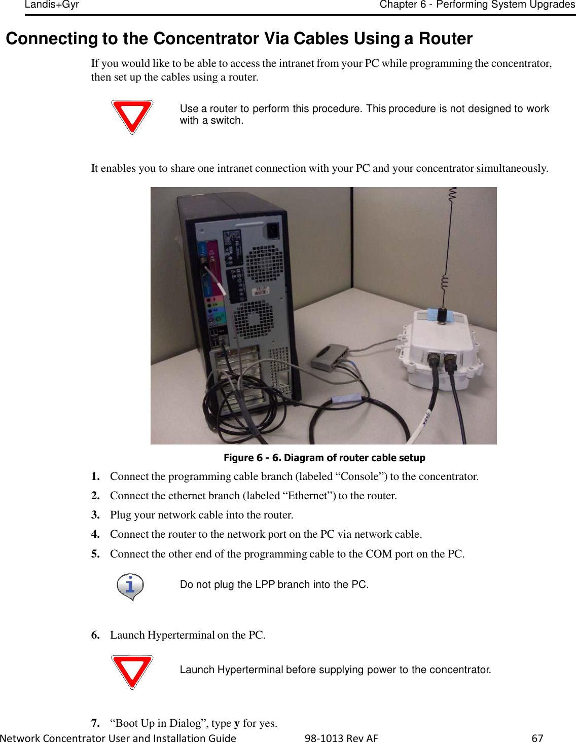
![Landis+Gyr Chapter 6 - Performing System Upgrades Network Concentrator User and Installation Guide 98-1013 Rev AF 64 Download Application Concentrator ID Session ID image.bin file locations Figure 6 - 5. Launch OTA download program The following table lists all the options in the download program: Table 6-1. Download Command Line Switches Switch Description Mccad Mccad is the concentrator address <net>.<node> which requires a firmware upgrade. Example: utlICDownload -mccad 30000.1 [Args Reqd: 1 defaults: 0.0 format: %lu] Session Session is a number between 0 - 255. This is the session ID of the download task for the concentrator. All operations for the download have the same session number. Example: utlICDownload -session 5 [Args Reqd: 1 defaults: 2 format: %lu] -s CIF file The code image file (CIF) of the new version to be downloaded on the concentrator is usually present in the / home/download/MCC_Cnctr/ directory. If the directory does not exist, create one and place the image.bin file in that directory. Verify that it is the correct version. Downloading an older or incorrect version can cause loss of communication with the concentrator. Example: utlICDownload -s /home/download/MCCCTR/ image.bin [Args Reqd: 1 defaults: 2 format: %s]](https://usermanual.wiki/Landis-Gyr-Technology/CONCS4B5/User-Guide-2014067-Page-65.png)
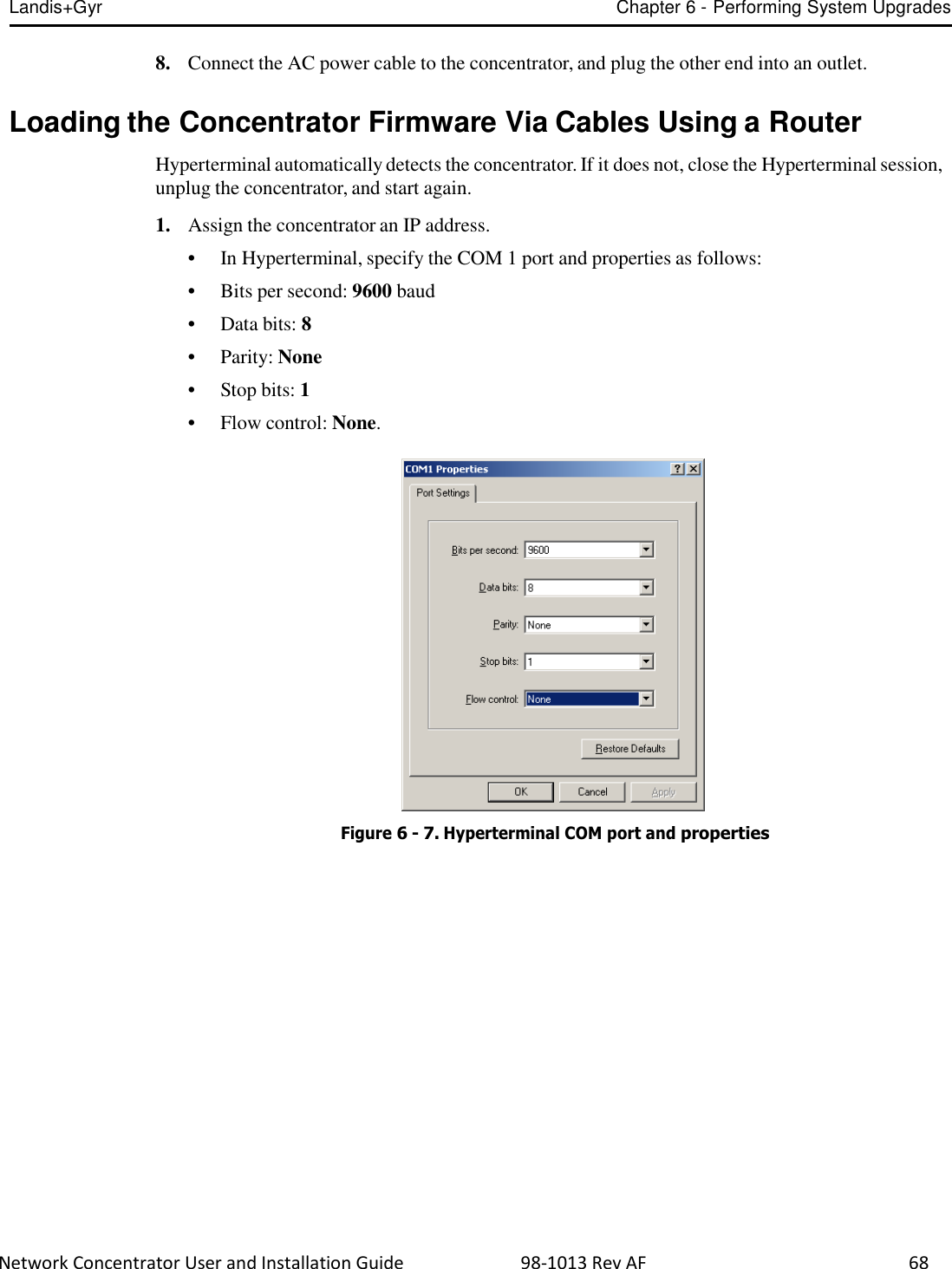
![Landis+Gyr Chapter 6 - Performing System Upgrades Network Concentrator User and Installation Guide 98-1013 Rev AF 65 Table 6-1. Download Command Line Switches (continued) Switch Description -disconnect You need the disconnect session ID if the earlier download was terminated before completion. In this case, you must enter all the options of the download command and include the disconnect session ID. That should be the same session number that was terminated earlier. Example: utlICDownload -disconnect 5 -nohotboot Override automatic disconnect and hotboot to avoid hot booting the MC be fore the session. In this case, you must start run disconnect and hotboot. Example: utlICDownload -nohotboot -session 5 -mccad 30000.1 -s <filename> -waittime Time to wait (in seconds) before sending the next packet. The download firmware process sends a total of nine packets. The waittime option allows for a delay between packets sent. Example: utlICDownload -waittime 4 /MCCCTR/image.bin [Args Reqd: 1 defaults: 2 format: %s] -bankcopy Copy Concentrator image from B to A. The Concentrator must be running the image from B. This option applies to versions 14.02.06 and greater. Example: utlICDownload -mccad 30000.1 -bankcopy -debugprint Dump raw hex. Example: utlICDownload -debugprint [Args Reqd: 1 defaults: 2 format: %s] -help Print help information. Example: utlICDownload -help -query Get status of concentrator. Example: utlICDownload -query -switchover Switchover concentrator. Example: utlICDownload -switchover Switchover Concentrator After the download is complete, login to the concentrator to instruct it to switchover. 1. Open a command window on your PC. 2. Use your administrative credentials to login as control user. 3. Type ./utlICDownload -mccad 30000.1 -session 2 -switchover The concentrator hot boots after this step.](https://usermanual.wiki/Landis-Gyr-Technology/CONCS4B5/User-Guide-2014067-Page-66.png)
![Landis+Gyr Chapter 6 - Performing System Upgrades Network Concentrator User and Installation Guide 98-1013 Rev AF 83 Upgrade the concentrator’s DCW with Network Configuration Manager tool, via direct or OTA connection. 1. Open the Network Configuration Manager tool. 2. Connect to the concentrator’s radio. 3. Click the Load DCW button. 4. Select the DCW from the file list. 5. Click the Open button. 6. The DCW loads and a series of messages display along the status bar of the Network Configuration Manager window. 7. Network Configuration Manager displays a message when the DCW loads successfully. The MCC Helper DCW displays in the DCW section of the window. Verify with customer support at ëçäìíáçåëìééçêíKå~]ä~åÇáëÖóêKÅçã that you have the most current version. For more information about working with DCWs, see the Network Configuration Manager Users Guide.](https://usermanual.wiki/Landis-Gyr-Technology/CONCS4B5/User-Guide-2014067-Page-84.png)
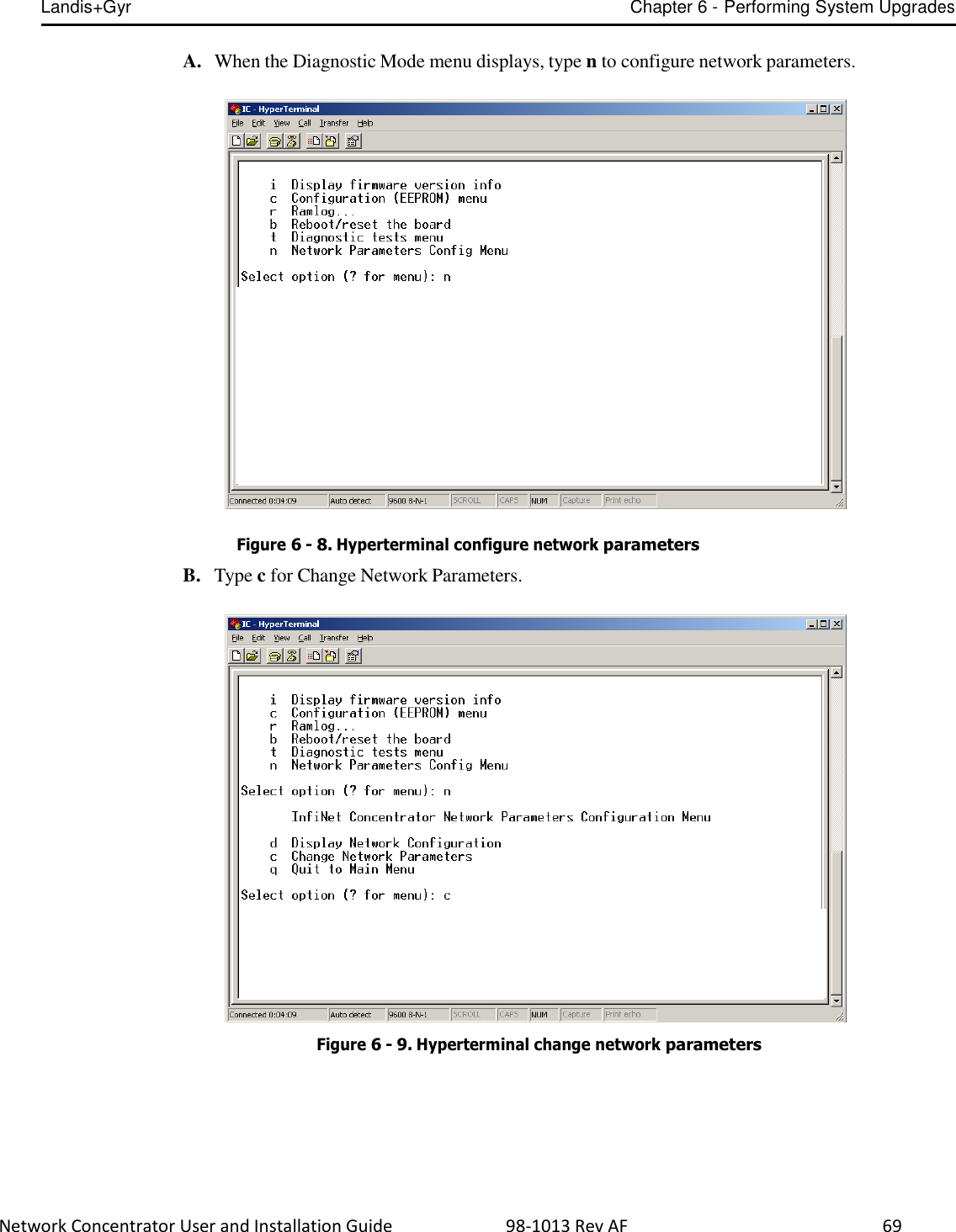
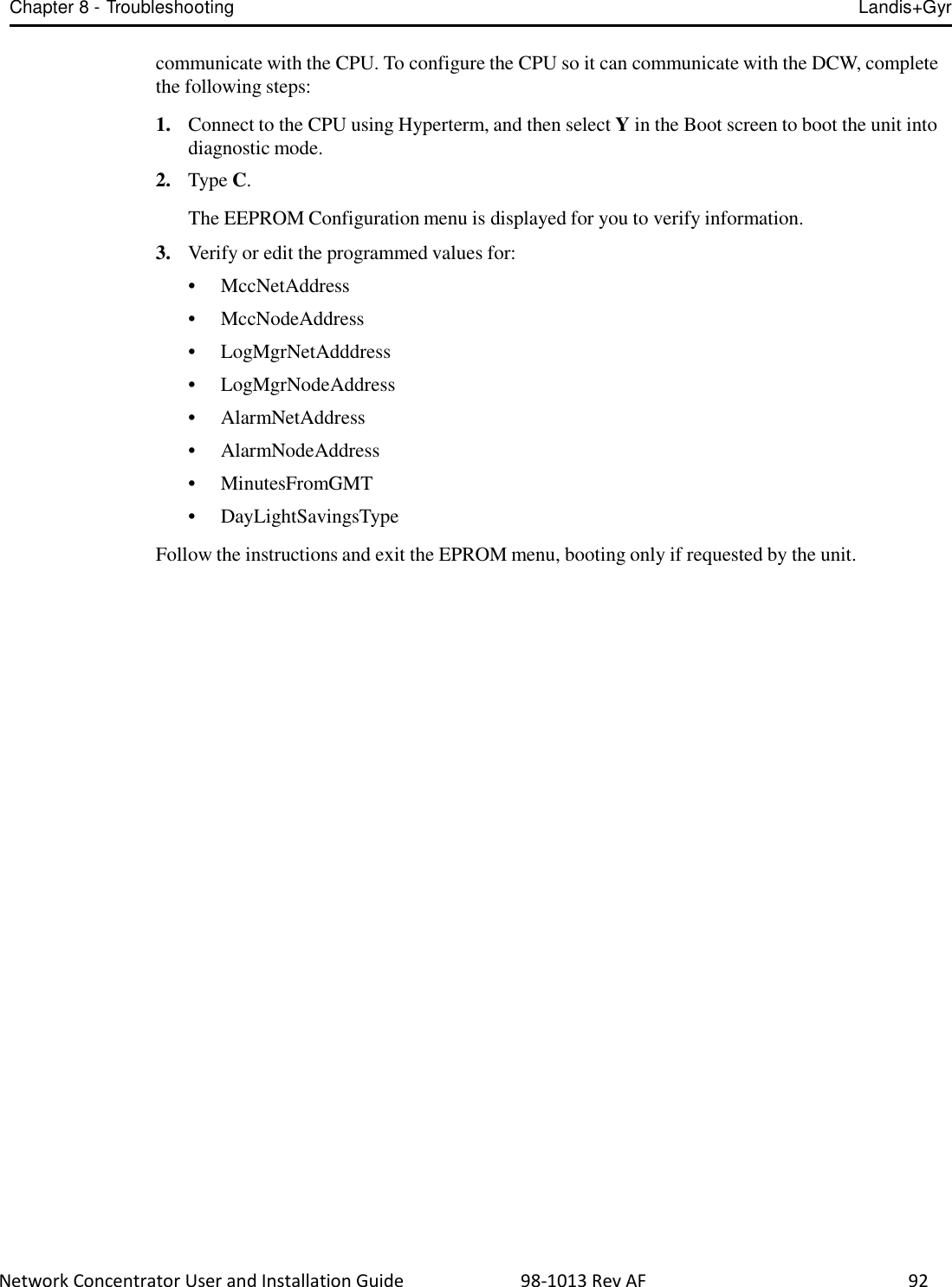
![Network Concentrator User and Installation Guide 98-1013 Rev AF 91 8 Troubleshooting This chapter lists common issues and steps to take to solve related problems. Contact Landis+Gyr Customer Operations at ëçäìíáçåëìééçêíKå~]ä~åÇáëÖóêKÅçã with questions. Verifying Configuration If the network does not discover a concentrator, verify that the correct Network ID and destination are programmed into the radio. If so, then verify that the radio can communicate with the TOP. The Network Configuration Manager application is required to perform these steps. To verify communications with the TOP, use the ping command in the Network Configuration Manager application. This sends a message to the TOP and back to verify the TOP exists. Ping while plugged directly into the concentrator via a cable or over the air via another radio from the ground that is connected to the concentrator. • If the ping is not successful, double-check the destination or choose another TOP. • If the ping is successful, ensure that the radio is able to read the MCCID in the CPU. To check the CPU, connect to the radio, and then locate the MCCID (in format MCC Helper v1.16a (130603) from the DCW list on the Network Configuration Manager main screen, as shown in Figure 8 - 1. Figure 8 - 1. MCCID If the MCCID is zero (in format MCC Helper v1.16a (0) from 4F.91.E6.20.92.1F [FE.FF.00.A7]), a CPU configuration failure occurred and the DCW was unable to](https://usermanual.wiki/Landis-Gyr-Technology/CONCS4B5/User-Guide-2014067-Page-90.png)
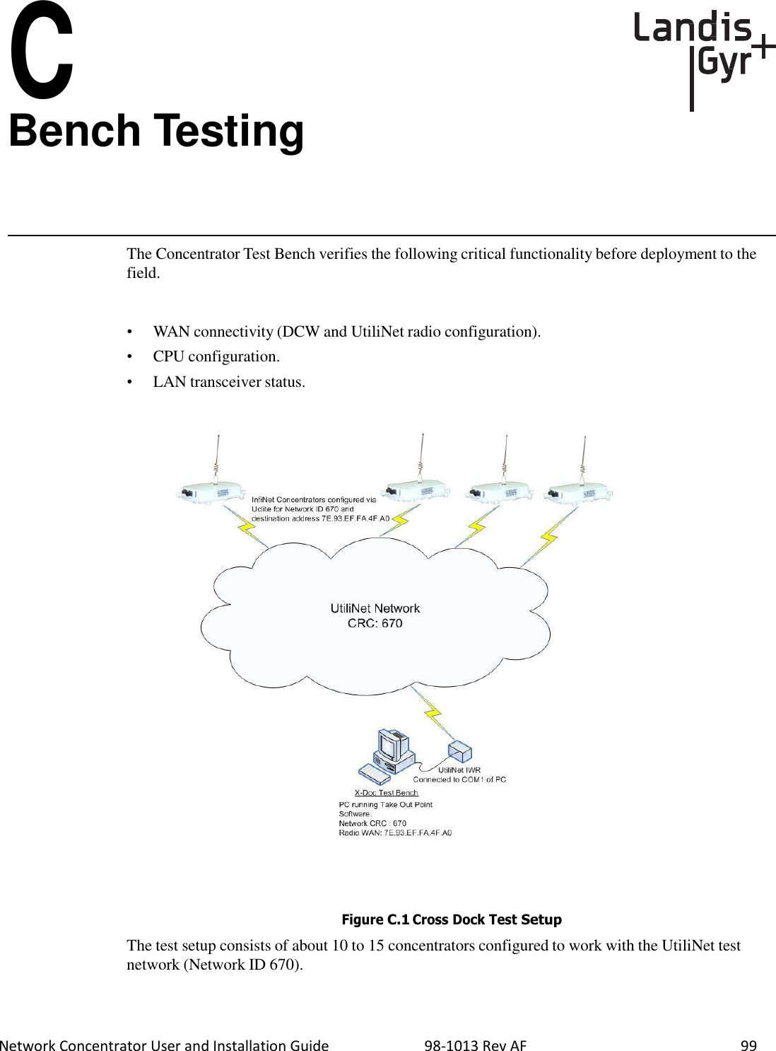
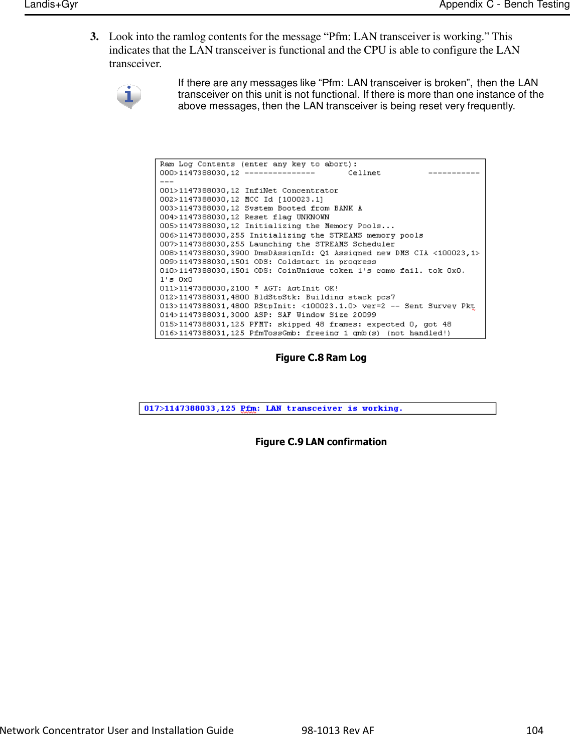
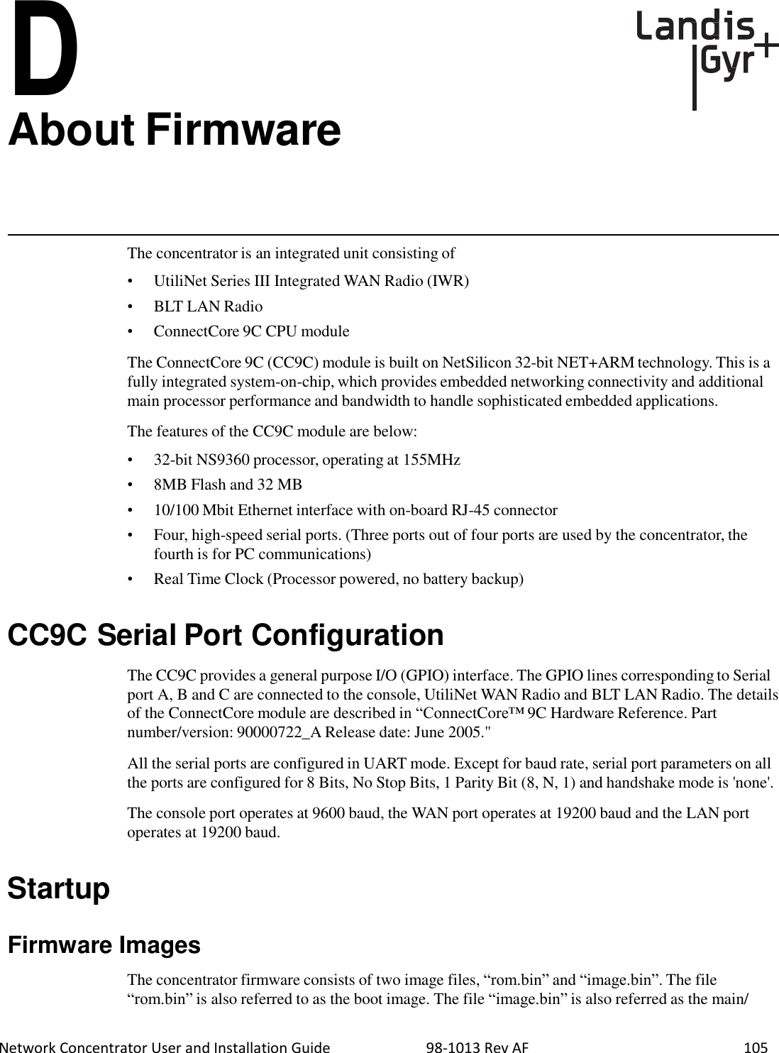
![Landis+Gyr Appendix C - Bench Testing Network Concentrator User and Installation Guide 98-1013 Rev AF 103 1. From the Main Menu, go to the EEPROM configuration menu and verify the relevant EEPROM configuration parameters. 2. From the concentrator EEPROM Configuration Menu display the configuration. Scroll down the page that starts with “+Asap store&forward evt group size [0..65535;default=14]: 14". 3. Verify that the following highlighted parameters are set to 0. Figure C.6 CPU Configuration Check 4. Scroll down to the page which starts with the configuration item “Gateway Concentrator Num of Cal objects stored in Flash [default=0]: 0". 5. Verify that the following highlighted parameters are set to the values as shown below. Figure C.7 Concentrator Parameters LAN Health Check The LAN health is determined from the concentrator's RAMLOG. 1. From the Concentrator Main Menu select option 'd'. The Concentrator Debug Menu appears. 2. Select option 'r', to get to Ramlog Menu. Use option “d” to dump the ramlog.](https://usermanual.wiki/Landis-Gyr-Technology/CONCS4B5/User-Guide-2014067-Page-100.png)