Landis Gyr Technology CONCS4B5 Series-4 Concentrator, BLT5 User Manual 12 0408 Exhibit Cover
Landis+Gyr Technology, Inc. Series-4 Concentrator, BLT5 12 0408 Exhibit Cover
Manual

5015 B.U. Bowman Drive Buford, GA 30518 USA Voice: 770-831-8048 Fax: 770-831-8598
Certification Exhibit
FCC ID: R7PCONCS4B5
FCC Rule Part: 15.247
ACS Project Number: 12-0408
Manufacturer: Landis+Gyr Technology, Inc.
Model: Series-4 Conc., BLT-5
Manual

Gridstream
Network
Concentrator User
and
Installation
Guide
Publication:
98-1013 Rev
AF

Limitation on Warranties and Liability
Information in this document is subject to change without notice. This manual or any part of it thereof may not be
reproduced in any form unless permitted by contract or by written permission of Landis+Gyr.
In no event will Landis+Gyr be liable for any incidental, indirect, special, or consequential damages (including lost
profits) arising out of or relating to this publication or the information contained in it, even if Landis+Gyr has been
advised, knew, or should have known of the possibility of such damages.
© 2010, 2013 Landis+Gyr, Inc. All Rights
Reserved.
Trademarks
WanGate®, Cellnet®, UtiliNet®, and RadioShop® are registered trademarks of Landis+Gyr.
Other brands or product names are the trademarks or registered trademarks of their respective holders.
Landis+Gyr Gridstream Network Concentrator User and Installation Guide
Publication: 98-1013 Rev AF
Revision History
Modification Date
Revision
Description
Author
7/17/2009
AB
Released
Randy Roten
9/17/2009
AC
Released
Randy Roten
5/26/2010
AD
Released
Randy Roten
11/19/10
AE
Released
Randy Roten
6/10/13
AF
In Process
Landis+Gyr
30000 Mill Creek Avenue
Suite 100
Alpharetta, GA 30022
Website: www.landisgyr.com
E-mail: solutionsupport.na@landisgyr.com
Technical Support: 1-888-390-5733
Copyright© 2010,2013
Landis+Gyr, Inc.
All rights reserved.

Network Concentrator User and Installation Guide 98-1013 Rev AF 2
Table of Contents
Chapter 1: Preface
. . . . . . . . . . . . . . . . . . . . . . . . . . . . . . . . . . . . . . . . . . . . . . . . . . . . . . . . . . . . . . . . . . 7
About
the
Landis+Gyr
Gridstream
Network
.
.
.
.
.
.
.
.
.
.
.
.
.
.
.
.
.
.
.
.
.
.
.
.
.
.
.
.
.
.
.
.
.
.
.
.
.
.
.
.
.
.
.
.
. 7
About the Concentrator . . . . . . . . . . . . . . . . . . . . . . . . . . . . . . . . . . . . . . . . . . . . . . . . . . . . . . . . . . . . . . . . . . . . 7
About This Guide . . . . . . . . . . . . . . . . . . . . . . . . . . . . . . . . . . . . . . . . . . . . . . . . . . . . . . . . . . . . . . . . . . . . . . . . 7
Who Should Use This Guide . . . . . . . . . . . . . . . . . . . . . . . . . . . . . . . . . . . . . . . . . . . . . . . . . . . . . . . . . 8
Typographical Conventions . . . . . . . . . . . . . . . . . . . . . . . . . . . . . . . . . . . . . . . . . . . . . . . . . . . . . . . . . . . . . . . . 8
Contacting Technical Support . . . . . . . . . . . . . . . . . . . . . . . . . . . . . . . . . . . . . . . . . . . . . . . . . . . . . . . . . . . . . . . 9
Telephone Access . . . . . . . . . . . . . . . . . . . . . . . . . . . . . . . . . . . . . . . . . . . . . . . . . . . . . . . . . . . . . . . . . 9
Email Access . . . . . . . . . . . . . . . . . . . . . . . . . . . . . . . . . . . . . . . . . . . . . . . . . . . . . . . . . . . . . . . . . . . . . 9
General Inquiries . . . . . . . . . . . . . . . . . . . . . . . . . . . . . . . . . . . . . . . . . . . . . . . . . . . . . . . . . . . . . . . . . 10
Chapter 2: Pre-Installation
. . . . . . . . . . . . . . . . . . . . . . . . . . . . . . . . . . . . . . . . . . . . . . . . . . . . . . . . . . 11
Safety Overview . . . . . . . . . . . . . . . . . . . . . . . . . . . . . . . . . . . . . . . . . . . . . . . . . . . . . . . . . . . . . . . . . . . . . . . . 11
Pre-Installation Checklist . . . . . . . . . . . . . . . . . . . . . . . . . . . . . . . . . . . . . . . . . . . . . . . . . . . . . . . . . . . . . . . . . 12
Getting Organized . . . . . . . . . . . . . . . . . . . . . . . . . . . . . . . . . . . . . . . . . . . . . . . . . . . . . . . . . . . . . . . . . . . . . . . 13
Concentrator Installation Tool List . . . . . . . . . . . . . . . . . . . . . . . . . . . . . . . . . . . . . . . . . . . . . . . . . . . 13
Install Material . . . . . . . . . . . . . . . . . . . . . . . . . . . . . . . . . . . . . . . . . . . . . . . . . . . . . . . . . . . . . . . . . . . 13
Chapter 3: Field Configuration
. . . . . . . . . . . . . . . . . . . . . . . . . . . . . . . . . . . . . . . . . . . . . . . . . . . . . . . 15
Required Tools . . . . . . . . . . . . . . . . . . . . . . . . . . . . . . . . . . . . . . . . . . . . . . . . . . . . . . . . . . . . . . . . . . . . . . . . . 15
Concentrator Programming Kit . . . . . . . . . . . . . . . . . . . . . . . . . . . . . . . . . . . . . . . . . . . . . . . . . . . . . . . . . . . . . 16
Writing Utility Network Parameters to the Concentrator . . . . . . . . . . . . . . . . . . . . . . . . . . . . . . . . . . . . . . . . . 17
Setting the Timekeeper Radio . . . . . . . . . . . . . . . . . . . . . . . . . . . . . . . . . . . . . . . . . . . . . . . . . . . . . . . . . . . . . . 17
Concentrator Configuration . . . . . . . . . . . . . . . . . . . . . . . . . . . . . . . . . . . . . . . . . . . . . . . . . . . . . . . . . . . . . . . 18
Disabling Network Filtering . . . . . . . . . . . . . . . . . . . . . . . . . . . . . . . . . . . . . . . . . . . . . . . . . . . . . . . . . . . . . . . 24
Chapter 4: Concentrator Installation
. . . . . . . . . . . . . . . . . . . . . . . . . . . . . . . . . . . . . . . . . . . . . . . . . . 29
Antenna Mounting Options . . . . . . . . . . . . . . . . . . . . . . . . . . . . . . . . . . . . . . . . . . . . . . . . . . . . . . . . . . . . . . . . 29
For All Installations . . . . . . . . . . . . . . . . . . . . . . . . . . . . . . . . . . . . . . . . . . . . . . . . . . . . . . . . . . . . . . . . . . . . . . 29
Concentrator Installation Sheet . . . . . . . . . . . . . . . . . . . . . . . . . . . . . . . . . . . . . . . . . . . . . . . . . . . . . . 29
Power Requirements . . . . . . . . . . . . . . . . . . . . . . . . . . . . . . . . . . . . . . . . . . . . . . . . . . . . . . . . . . . . . . 29
Power Cable Preparation . . . . . . . . . . . . . . . . . . . . . . . . . . . . . . . . . . . . . . . . . . . . . . . . . . . . . . . . . . . 30
Adding Drip Loops to Cables . . . . . . . . . . . . . . . . . . . . . . . . . . . . . . . . . . . . . . . . . . . . . . . . . . . . . . . 30
Kit Part Numbers . . . . . . . . . . . . . . . . . . . . . . . . . . . . . . . . . . . . . . . . . . . . . . . . . . . . . . . . . . . . . . . . . 31
Concentrator Assembly . . . . . . . . . . . . . . . . . . . . . . . . . . . . . . . . . . . . . . . . . . . . . . . . . . . . . . . . . . . . . . . . . . . 32
Optional Parts . . . . . . . . . . . . . . . . . . . . . . . . . . . . . . . . . . . . . . . . . . . . . . . . . . . . . . . . . . . . . . . . . . . . 32
Wood Pole Mount Installation . . . . . . . . . . . . . . . . . . . . . . . . . . . . . . . . . . . . . . . . . . . . . . . . . . . . . . . . . . . . . 33
Wood Pole Mounting Kit . . . . . . . . . . . . . . . . . . . . . . . . . . . . . . . . . . . . . . . . . . . . . . . . . . . . . . . . . . . 34
Wood Pole Installation Procedure . . . . . . . . . . . . . . . . . . . . . . . . . . . . . . . . . . . . . . . . . . . . . . . . . . . . 35
Network Concentrator User and Installation Guide 98-1013 Rev AF 3
Metal Pole vertical Mount Installation . . . . . . . . . . . . . . . . . . . . . . . . . . . . . . . . . . . . . . . . . . . . . . . . . . . . . . . 37

Table of Contents
Landis+Gyr
Network Concentrator User and Installation Guide 98-1013 Rev AF 4
Concentrator Metal Pole Mounting Kit . . . . . . . . . . . . . . . . . . . . . . . . . . . . . . . . . . . . . . . . . . . . . . . .37
Metal Pole Installation Procedure . . . . . . . . . . . . . . . . . . . . . . . . . . . . . . . . . . . . . . . . . . . . . . . . . . . . .39
Streetlight Arm Horizontal Mount Installation . . . . . . . . . . . . . . . . . . . . . . . . . . . . . . . . . . . . . . . . . . . . . . . . .45
Concentrator Streetlight Arm Mounting Kit . . . . . . . . . . . . . . . . . . . . . . . . . . . . . . . . . . . . . . . . . . . .45
Streetlight Arm Installation Procedure . . . . . . . . . . . . . . . . . . . . . . . . . . . . . . . . . . . . . . . . . . . . . . . . .47
Chapter 5: RF Filter and Battery Replacement Kits
. . . . . . . . . . . . . . . . . . . . . . . . . . . . . . . . . . . . . . . .51
Enable/Disable RF Filter . . . . . . . . . . . . . . . . . . . . . . . . . . . . . . . . . . . . . . . . . . . . . . . . . . . . . . . . . . .51
Retrofitting a Series III Concentrator with an RF Filter . . . . . . . . . . . . . . . . . . . . . . . . . . . . . . . . . . . . . . . . . .52
Performing an RF Filter Retrofit . . . . . . . . . . . . . . . . . . . . . . . . . . . . . . . . . . . . . . . . . . . . . . . . . . . . .53
About Battery Storage . . . . . . . . . . . . . . . . . . . . . . . . . . . . . . . . . . . . . . . . . . . . . . . . . . . . . . . . . . . . . . . . . . . .56
Battery Test . . . . . . . . . . . . . . . . . . . . . . . . . . . . . . . . . . . . . . . . . . . . . . . . . . . . . . . . . . . . . . . . . . . . . . . . . . . .56
Replacement materials . . . . . . . . . . . . . . . . . . . . . . . . . . . . . . . . . . . . . . . . . . . . . . . . . . . . . . . . . . . . . . . . . . . .57
Concentrator Battery Pack Replacement Kit . . . . . . . . . . . . . . . . . . . . . . . . . . . . . . . . . . . . . . . . . . . .57
Replacing the Battery Pack . . . . . . . . . . . . . . . . . . . . . . . . . . . . . . . . . . . . . . . . . . . . . . . . . . . . . . . . . . . . . . . .58
Chapter 6: Performing System Upgrades
. . . . . . . . . . . . . . . . . . . . . . . . . . . . . . . . . . . . . . . . . . . . . . .61
What Are System Upgrades? . . . . . . . . . . . . . . . . . . . . . . . . . . . . . . . . . . . . . . . . . . . . . . . . . . . . . . . . . . . . . . .61
Accessing a Concentrator for Programming . . . . . . . . . . . . . . . . . . . . . . . . . . . . . . . . . . . . . . . . . . . . . . . . . . .61
Upgrading a Concentrator Over the Air (OTA) . . . . . . . . . . . . . . . . . . . . . . . . . . . . . . . . . . . . . . . . . . . . . . . .61
About the Image File . . . . . . . . . . . . . . . . . . . . . . . . . . . . . . . . . . . . . . . . . . . . . . . . . . . . . . . . . . . . . .61
Verifying the Concentrator and the Host . . . . . . . . . . . . . . . . . . . . . . . . . . . . . . . . . . . . . . . . . . . . . . .62
Hot-Booting a Concentrator . . . . . . . . . . . . . . . . . . . . . . . . . . . . . . . . . . . . . . . . . . . . . . . . . . . . . . . . .63
Downloading Firmware OTA . . . . . . . . . . . . . . . . . . . . . . . . . . . . . . . . . . . . . . . . . . . . . . . . . . . . . . . .64
Switchover Concentrator . . . . . . . . . . . . . . . . . . . . . . . . . . . . . . . . . . . . . . . . . . . . . . . . . . . . . . . . . . .66
Concentrator Verification . . . . . . . . . . . . . . . . . . . . . . . . . . . . . . . . . . . . . . . . . . . . . . . . . . . . . . . . . . .67
Bankcopy MCC . . . . . . . . . . . . . . . . . . . . . . . . . . . . . . . . . . . . . . . . . . . . . . . . . . . . . . . . . . . . . . . . . .67
Restarting a Download . . . . . . . . . . . . . . . . . . . . . . . . . . . . . . . . . . . . . . . . . . . . . . . . . . . . . . . . . . . . .67
Upgrading Concentrator Firmware Directly via Cable . . . . . . . . . . . . . . . . . . . . . . . . . . . . . . . . . . . . . . . . . . .67
Connecting to the Concentrator Via Cables Using a Router . . . . . . . . . . . . . . . . . . . . . . . . . . . . . . . .68
Loading the Concentrator Firmware Via Cables Using a Router . . . . . . . . . . . . . . . . . . . . . . . . . . . . .69
Testing the Concentrator . . . . . . . . . . . . . . . . . . . . . . . . . . . . . . . . . . . . . . . . . . . . . . . . . . . . . . . . . . .82
Upgrading IWR Radio Firmware . . . . . . . . . . . . . . . . . . . . . . . . . . . . . . . . . . . . . . . . . . . . . . . . . . . . . . . . . . .83
Upgrading the Radio’s DCW . . . . . . . . . . . . . . . . . . . . . . . . . . . . . . . . . . . . . . . . . . . . . . . . . . . . . . . . . . . . . . .83
Chapter 7: Routers in Command Center
. . . . . . . . . . . . . . . . . . . . . . . . . . . . . . . . . . . . . . . . . . . . . . . . .85
Importing Routers into Command Center . . . . . . . . . . . . . . . . . . . . . . . . . . . . . . . . . . . . . . . . . . . . . . . . . . . . .85
Generating the Import Installation File (IIF) . . . . . . . . . . . . . . . . . . . . . . . . . . . . . . . . . . . . . . . . . . . .85
Time Zone . . . . . . . . . . . . . . . . . . . . . . . . . . . . . . . . . . . . . . . . . . . . . . . . . . . . . . . . . . . . . . . . . . . . . . .87
RF Network Settings . . . . . . . . . . . . . . . . . . . . . . . . . . . . . . . . . . . . . . . . . . . . . . . . . . . . . . . . . . . . . . . . . . . . .88
Command Center Operation . . . . . . . . . . . . . . . . . . . . . . . . . . . . . . . . . . . . . . . . . . . . . . . . . . . . . . . . . . . . . . .88
Router . . . . . . . . . . . . . . . . . . . . . . . . . . . . . . . . . . . . . . . . . . . . . . . . . . . . . . . . . . . . . . . . . . . . . . . . . .88
Chapter 8: Troubleshooting
. . . . . . . . . . . . . . . . . . . . . . . . . . . . . . . . . . . . . . . . . . . . . . . . . . . . . . . . . .91
Verifying Configuration . . . . . . . . . . . . . . . . . . . . . . . . . . . . . . . . . . . . . . . . . . . . . . . . . . . . . . . . . . . . . . . . . .91
Appendix A: Performance
. . . . . . . . . . . . . . . . . . . . . . . . . . . . . . . . . . . . . . . . . . . . . . . . . . . . . . . . . . . .93
Product Specifications . . . . . . . . . . . . . . . . . . . . . . . . . . . . . . . . . . . . . . . . . . . . . . . . . . . . . . . . . . . . . . . . . . . .93

Table of Contents
Landis+Gyr
Network Concentrator User and Installation Guide 98-1013 Rev AF 5
Power Statistics . . . . . . . . . . . . . . . . . . . . . . . . . . . . . . . . . . . . . . . . . . . . . . . . . . . . . . . . . . . . . . . . . . . . . . . . .94

Network Concentrator User and Installation Guide 98-1013 Rev AF 6
Landis+Gyr Table of Co
nt
en
ts
WAN Statistics . . . . . . . . . . . . . . . . . . . . . . . . . . . . . . . . . . . . . . . . . . . . . . . . . . . . . . . . . . . . . . . . . . . . . . . . . 94
Appendix B: Compliance
. . . . . . . . . . . . . . . . . . . . . . . . . . . . . . . . . . . . . . . . . . . . . . . . . . . . . . . . . . . . 97
FCC Class B . . . . . . . . . . . . . . . . . . . . . . . . . . . . . . . . . . . . . . . . . . . . . . . . . . . . . . . . . . . . . . . . . . . . . . . . . . . 97
RF Exposure . . . . . . . . . . . . . . . . . . . . . . . . . . . . . . . . . . . . . . . . . . . . . . . . . . . . . . . . . . . . . . . . . . . . . 97
Appendix C: Bench Testing
. . . . . . . . . . . . . . . . . . . . . . . . . . . . . . . . . . . . . . . . . . . . . . . . . . . . . . . . . . 99
Testing Concentrators . . . . . . . . . . . . . . . . . . . . . . . . . . . . . . . . . . . . . . . . . . . . . . . . . . . . . . . . . . . . . . . . . . . 100
Configuration . . . . . . . . . . . . . . . . . . . . . . . . . . . . . . . . . . . . . . . . . . . . . . . . . . . . . . . . . . . . . . . . . . . 100
Verification . . . . . . . . . . . . . . . . . . . . . . . . . . . . . . . . . . . . . . . . . . . . . . . . . . . . . . . . . . . . . . . . . . . . 100
WAN Health Check . . . . . . . . . . . . . . . . . . . . . . . . . . . . . . . . . . . . . . . . . . . . . . . . . . . . . . . . . . . . . . 101
CPU Configuration Check . . . . . . . . . . . . . . . . . . . . . . . . . . . . . . . . . . . . . . . . . . . . . . . . . . . . . . . . . 102
LAN Health Check . . . . . . . . . . . . . . . . . . . . . . . . . . . . . . . . . . . . . . . . . . . . . . . . . . . . . . . . . . . . . . . 103
Appendix D: About Firmware
. . . . . . . . . . . . . . . . . . . . . . . . . . . . . . . . . . . . . . . . . . . . . . . . . . . . . . . 105
CC9C Serial Port Configuration . . . . . . . . . . . . . . . . . . . . . . . . . . . . . . . . . . . . . . . . . . . . . . . . . . . . . . . . . . . 105
Startup . . . . . . . . . . . . . . . . . . . . . . . . . . . . . . . . . . . . . . . . . . . . . . . . . . . . . . . . . . . . . . . . . . . . . . . . . . . . . . . 105
Firmware Images . . . . . . . . . . . . . . . . . . . . . . . . . . . . . . . . . . . . . . . . . . . . . . . . . . . . . . . . . . . . . . . . 105
Initialization and Boot Image Loading . . . . . . . . . . . . . . . . . . . . . . . . . . . . . . . . . . . . . . . . . . . . . . . 106
Application Image Loading . . . . . . . . . . . . . . . . . . . . . . . . . . . . . . . . . . . . . . . . . . . . . . . . . . . . . . . . . . . . . . . 106
Application Image Startup . . . . . . . . . . . . . . . . . . . . . . . . . . . . . . . . . . . . . . . . . . . . . . . . . . . . . . . . . 106
Concentrator Boot-Up . . . . . . . . . . . . . . . . . . . . . . . . . . . . . . . . . . . . . . . . . . . . . . . . . . . . . . . . . . . . 106
Diagnostics Mode . . . . . . . . . . . . . . . . . . . . . . . . . . . . . . . . . . . . . . . . . . . . . . . . . . . . . . . . . . . . . . . . . . . . . . 107
Diagnostics Mode . . . . . . . . . . . . . . . . . . . . . . . . . . . . . . . . . . . . . . . . . . . . . . . . . . . . . . . . . . . . . . . 107
Network Parameters Configuration Menu . . . . . . . . . . . . . . . . . . . . . . . . . . . . . . . . . . . . . . . . . . . . . 108
Diagnostics Tests Menu . . . . . . . . . . . . . . . . . . . . . . . . . . . . . . . . . . . . . . . . . . . . . . . . . . . . . . . . . . . 108
Application Mode . . . . . . . . . . . . . . . . . . . . . . . . . . . . . . . . . . . . . . . . . . . . . . . . . . . . . . . . . . . . . . . . . . . . . . 109
TIME from UtiliNet Network . . . . . . . . . . . . . . . . . . . . . . . . . . . . . . . . . . . . . . . . . . . . . . . . . . . . . . 110
Application Troubleshooting without TIME . . . . . . . . . . . . . . . . . . . . . . . . . . . . . . . . . . . . . . . . . . . 110
Persistent Data Storage . . . . . . . . . . . . . . . . . . . . . . . . . . . . . . . . . . . . . . . . . . . . . . . . . . . . . . . . . . . . . . . . . . 110
Data Storage . . . . . . . . . . . . . . . . . . . . . . . . . . . . . . . . . . . . . . . . . . . . . . . . . . . . . . . . . . . . . . . . . . . . 110
Impact of Boot-up on Data Storage . . . . . . . . . . . . . . . . . . . . . . . . . . . . . . . . . . . . . . . . . . . . . . . . . . 111
Capacity . . . . . . . . . . . . . . . . . . . . . . . . . . . . . . . . . . . . . . . . . . . . . . . . . . . . . . . . . . . . . . . . . . . . . . . 111
Cycling Power . . . . . . . . . . . . . . . . . . . . . . . . . . . . . . . . . . . . . . . . . . . . . . . . . . . . . . . . . . . . . . . . . . . . . . . . . 111
Appendix E: About Programming and Diagnostic Cables
. . . . . . . . . . . . . . . . . . . . . . . . . . . . . . . . . 113
Appendix F: Sample Survey Sheet
. . . . . . . . . . . . . . . . . . . . . . . . . . . . . . . . . . . . . . . . . . . . . . . . . . . 115
Appendix G: Field Upgrade to DCW 1.16F
. . . . . . . . . . . . . . . . . . . . . . . . . . . . . . . . . . . . . . . . . . . . . . 117
Changing 9QPR-based MCC to a Gridstream-based Concentrator . . . . . . . . . . . . . . . . . . . . . . . . . . . . . . . . 117
Upgrading DCW and Losing Default Destination . . . . . . . . . . . . . . . . . . . . . . . . . . . . . . . . . . . . . . . . . . . . . 117
Upgrade Issues . . . . . . . . . . . . . . . . . . . . . . . . . . . . . . . . . . . . . . . . . . . . . . . . . . . . . . . . . . . . . . . . . . 117
Appendix H: Power Cable Installation
. . . . . . . . . . . . . . . . . . . . . . . . . . . . . . . . . . . . . . . . . . . . . . . . 119
Power Connection and Termination . . . . . . . . . . . . . . . . . . . . . . . . . . . . . . . . . . . . . . . . . . . . . . . . . . . . . . . . 119

Table of Contents
Landis+Gyr
Network Concentrator User and Installation Guide 98-1013 Rev AF 7
Glossary
. . . . . . . . . . . . . . . . . . . . . . . . . . . . . . . . . . . . . . . . . . . . . . . . . . . . . . . . . . . . . . . . . . . . . . . . .123
Index
. . . . . . . . . . . . . . . . . . . . . . . . . . . . . . . . . . . . . . . . . . . . . . . . . . . . . . . . . . . . . . . . . . . . . . . . . . . .125

Network Concentrator User and Installation Guide 98-1013 Rev AF 8
1
Pr
eface
This guide describes the installation process for Gridstream Network Concentrators (concentrators).
Any training provided directly to installers by the utility or by the Gridstream project management
team takes precedence over this guide.
About the Landis+Gyr Gridstream
Network
The Gridstream Automated Metering Infrastructure (AMI) network transfers information from a
number of endpoints distributed over a large geographical area. The most common endpoints are
from electrical, gas and water endpoints. The network includes a Radio Frequency (RF) Wide Area
Network (WAN) and an RF Local Area Network (LAN). The WAN includes Take Out Points (TOP)
and concentrators. The LAN is the RF link between the concentrator and endpoints with UtiliNet
modules installed. Endpoint data transmits via radio frequency (RF) to the concentrator where it is
stored and processed. The concentrator transmits the data via RF to the TOP and then to the utility.
This chapter details the concentrator installation process.
About the Concentrator
The Concentrator is a device that receives one-way endpoint data from the Gridstream network,
processes that data, and sends it to a Collector (Take Out Point, or TOP). It also receives and passes,
but does not process, 2-way data. The concentrator contains:
• a LAN radio (BLT 3 or BLT 5)
• a WAN radio (UtiliNet IWR)
• a power supply
• a processor board (CPU)
• a battery pack in case of an AC power outage.
About This Guide
This edition of the Landis+Gyr Gridstream Concentrator User and Installation Guide provides:
• Basic installation procedure for concentrators.
• A task-based overview of detailed instructions for using concentrators.

Chapter 1 - Preface
Landis+Gyr
Network Concentrator User and Installation Guide 98-1013 Rev AF 9
Who Should Use This Guide
This guide is intended for use by utility employees or the Landis+Gyr project team responsible for
installing concentrators. It does not assume an expert level of industry or computer knowledge. This
guide assumes that you are familiar with basic:
– Utility operations.
– Terminology of your industry.
– Procedures for performing basic laptop computer operations.
Typographical Conventions
This section describes the conventions used in this guide to make finding and understanding
information easier. Text formatting identifies special information.
Convention Description
All Bold, initial capital letters Refers to field names, buttons, menus, menu options, and
keys. Examples: Device field, Open button, File menu, or
Ctrl key.
All bold lower-case letters Refers to the exact keystrokes you enter. What you type is
always shown in lowercase letters. Example: Type local in
the Device field.
Lower-case italicized word
between less-than (<) and
greater-than signs (>)
<menu> | <option> |
<option>...
Refers to variables that occur in item names. Example:
Add Sub Network To <network name> dialog, where
<network name> refers to the name of a network.
Refers to the sequence of choices you should make to
access a specific dialog or menu option. Examples: choose
Start | Settings | Control Panel or choose File | Open.
Plus sign (+) between keys Refers to pressing the keys at the same time. Example:
Alt+B
.
Comma (,) between keys Refers to keys which are pressed sequentially. Example:
Alt,F
.
Note boxes provide essential information about concentrator Installation.
Cautions provide information that must read to avoid making relatively
moderate errors during concentrator Installation.

Network Concentrator User and Installation Guide 98-1013 Rev AF 10
Landis+Gyr Chapter 1 - Preface
Warnings provide special must-read information. If you ignore a warning,
you may omit essential data or make a critical error. Warnings are in the
same format as notes, except they are shown in bold tex
t
.
Contacting Technical Support
Within the United States, Landis+Gyr technical support is available by telephone or email. When
you contact technical support, be prepared to give exact descriptions of:
• The problem you encountered
• What happened and what you were doing when the problem occurred
• How you tried to solve the problem
• The exact text of any error messages
Telephone Access
Technical support is available Monday through Friday from 8:00 a.m. to 5:00 p.m. (EST) by calling
1-888-390-5733. If all support technicians are helping other customers, your call will be routed to
the Landis+Gyr Support voice mail system.
Leave a brief message that includes the following information:
• Your name
• Your company’s name
• Your telephone number
A support technician will return your call as soon as possible within normal business hours.
Technicians return all calls in the order that they are received.
Email Access
If you prefer, you may email a description of your problem to:
solutionsupport.na@landisgyr.com
A support technician will return your email as soon as possible within normal business hours.
Technicians return all emails in the order that they are received.

Chapter 1 - Preface
Landis+Gyr
Network Concentrator User and Installation Guide 98-1013 Rev AF 11
General Inquiries
Your feedback is important in helping to provide accurate and high-quality information. If you want
to reach a Landis+Gyr sales representative, or for other inquires, do one of the following:
• Telephone: 678-258-1500
• Fax: 678-258-1550
You can also mail your comments or inquires to:
Landis+Gyr
30000 Mill Creek Avenue
Suite 100
Alpharetta, GA 30022
Ordering Publications
You can order publications from your sales representative. To order additional copies of this manual,
use order number:
98‐1013 Rev
AE
Publication Comments
If you have remarks or suggestions for improving this publication, Landis+Gyr welcomes your
feedback and recommendations. Landis+Gyr accepts comments via email, conventional mail, or fax.
To send
your
comments
via...
Use this contact
information...
E-Mail
solutionsupport.na@landisgyr.com
Mail
Landis+Gyr
30000 Mill Creek Avenue
Suite 100
Alpharetta, GA 30022
Fax
678-258-1550
If you would like a reply, please include your contact information:
• Name
• Telephone number or fax number
• Email address
• Company name and address
Be sure to include the following information along with your comment:
• Title and number of this manual (Landis+Gyr Gridstream Network Concentrator User and
Installation Guide Rev AE, 98‐1013)
• Page number or topic related to your comment
Landis+Gyr reserves the right to use or distribute whatever information you supply in any way we
believe appropriate without incurring any obligation to you.

Network Concentrator User and Installation Guide 98-1013 Rev AF 12
2
Pr
e-Installation
Proper planning and thorough preparation are critical to successful Concentrator installation. This
chapter outlines basic requirements for the pre-installation phase of the concentrator deployment
process.
Safety Overview
Prior to starting the installation process, you must develop and launch an installer safety training
plan for initial, refresher, and ongoing safety training. Ensure that installers receive appropriate
initial and refresher training to meet their specific safety-related responsibilities. You must provide
safety training when:
• an existing installer assumes new duties for which they have not previously received training.
• new processes and methodologies representing new risks are introduced into the installation
environment.
• previously unidentified risks are reported.
The installation supervisory team assumes responsibility for ensuring that installers are properly
trained, authorized, and continually qualified to perform their work. The team must also take
responsibility for the safety of their installers and to assure safe work methodologies. Installers must
understand that their supervisor’s responsibility does not relieve them from their individual
responsibility to perform the work safely and to follow all safety rules and procedures applicable to
their work.

Chapter 2 - Pre-Installation
Landis+Gyr
Network Concentrator User and Installation Guide 98-1013 Rev AF 13
Pre-Installation Checklist
Be prepared before you go onsite. The following list includes most pre-install items.
Table 2-1. Pre-Install Checklist
Item
Description
Site Survey
The utility has surveyed the area to determine optimal
locations for concentrator installation. Landis+Gyr offers
this professional service as a contract option.
Obtain Necessary Permits
When the concentrator is to be installed on utility or
municipal property such as utility poles, there is a general
agreement to install on these poles. There may be a
requirement for the utility or municipality to approve
individual sites. It is the installer's responsibility to ensure
that approval has been given for each installation.
Network Installation Timeline
The Network Installation Plan specifies and formalizes the
entire concentrator installation plan. Perform all surveys in
advance to ensure ample time for make-ready work as well
as addressing any unforeseen installation issues. All
concentrators will be installed, quality-checked, and online
prior to any endpoint installation in a scheduled route.
Tools and Equipment
The latter part of this chapter has detailed tool and
equipment information.
Bucket Truck
Procure all necessary barricade and traffic permits for
the bucket truck as required, unless covered by prior
permits.
Supervision
Your organization has rules regarding supervision in the
field. If you note any deviation from the specified installation
criteria, contact your supervisor immediately.
ID Badges
Your identification badge should be clearly visible at all times.
If you lose or damage your ID, notify your Field Supervisor
immediately to get a replacement. You are not allowed to
work in the field without one.

Network Concentrator User and Installation Guide 98-1013 Rev AF 14
Landis+Gyr Chapter 2 - Pre-Installation
Getting Organized
Concentrator Installation Tool List
• Gas or hydraulic-powered drill, 3/4 inch augur bit
• Two adjustable-end wrenches
• Squeeze-on crimpers and crimps
• Standard socket wrench set
• Laptop computer with two serial ports
• Concentrator and applicable install kit
• Concentrator programming cable
• Network Configuration Manager application
• Concentrator power cable with standard 120VAC outlet
• Survey sheet
• Hyperterminal application
• Personal Protection Equipment
• Voltmeter
• Cell phone or 2-way communication device
Additional Tools Required for Street Light or Traffic Signal Pole Installs
• Steel banding tool
• Tin snips
• Hammer
Additional
Tools Required for
Building
and Structure Installs
• Steel banding tool
• Hammer drill
• Bits
Install
Mater
i
al
The installation process consists of using predetermined route information identifying concentrators
that need to be installed and methods for recording data to document the installation.
From the Cross-Dock, obtain concentrators and installation kits to install.

Network Concentrator User and Installation Guide 98-1013 Rev AF 15
3
Field Configuration
Configure the concentrator prior to installation. Steps include:
1. Configure the IWR radio (using Network Configuration Manager).
2. Program the concentrator.
3. Write network settings to the concentrator.
Required Tools
To perform field configuration, you need the following:
• PC with two serial ports or USB-to-serial adapter.
• Concentrator programming Kit 45-1046 (see About Programming and Diagnostic Cables for
more information).
• Network Configuration Manager.
• Hyperterminal (a communications accessory that comes bundled with the Windows Operating
System prior to the Vista release, and available free
on-line).
Landis+Gyr
Chapter 3 - Field Configur
a
t
ion
Network Concentrator User and Installation Guide 98-1013 Rev AF 16
Concentrator Programming Kit
The Programming Kit includes all the parts you need to configure the concentrator.
Table 3-1. Concentrator Programming Kit
45-1046
Image
Part Number
Name
Quantity
105628-000
CABLE ASSY, WANGATE, AC POWER,
120VAC PLUG
1
19-1027
CBL ASM, EXTERNAL RF, S3 IWR
1
19-1185
Cable Assy, RS-232 Prog, Infinet
Concentrator, Phase 2
1
19-1135
CBL ASSY, DB9M TO DB9F, SERIAL,
10FT
1
26-1046
T/A, RADIO, S3, IWR
1
Landis+Gyr
Chapter 3 - Field Configur
a
t
ion
Network Concentrator User and Installation Guide 98-1013 Rev AF 17
Table 3-1. Concentrator Programming Kit 45-1046 (continued)
26-1061
T/A, 120 VAC POWER ADAPTER
CUBE, S3 IWR, 1000mA
1
Writing Utility Network Parameters to the Concentrator
After the concentrator is successfully powered up, you can restore (or) configure the concentrator to
the utility network parameters.
Use the Network Configuration Manager application to complete this process. See the Network
Configuration Manager Users Guide for information about using this application to preform the
following:
1. Verify that the Network ID is setup for the utility Network and the default destination points to
the appropriate Take Out Point.
2. Verify that the Concentrator “MCCTIME” Helper DCW is loaded correctly in the UtiliNet IWR
Radio of this Concentrator.
Setting the Timekeeper Radio
If you can access network time over the air, then use network time. If you are in a location that
cannot access network time, then set up the local test IWR radio as a timekeeper before beginning
the configuration process. The concentrator does not start processing until it detects time.
Using a local test IWR radio as timekeeper can destroy network time
ke
eping
capability if used within the network’s detection area.
1. Connect the radio to COM2 via serial cable (PN 19-1135).
2. Connect power to the radio via the power adapter (PN 26-1061).
3. Launch Network Configuration Manager on your PC.
4. Select the “Timekeeper” option.
5. Click the Write Settings button.
The radio remains powered and connected to the PC during the configuration process.
Landis+Gyr
Chapter 3 - Field Configur
a
t
ion
Network Concentrator User and Installation Guide 98-1013 Rev AF 18
Concentrator Configuration
Follow the steps for configuring the Concentrator:
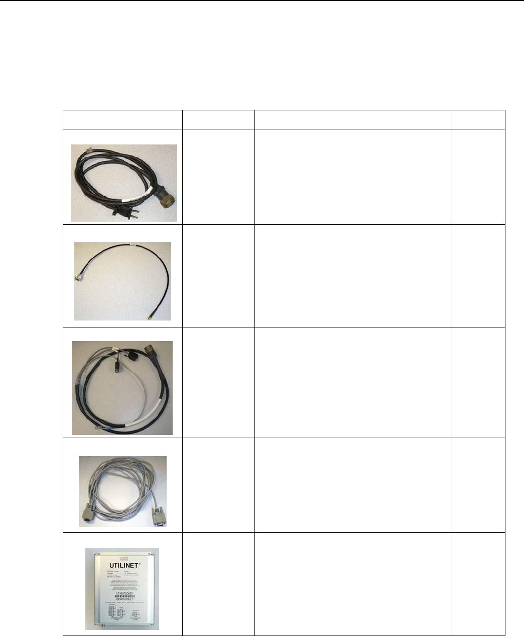
1. Plug the concentrator programming cable into the left-most barrel connector on the concentrator.
Figure
3 - 1.
Concentrator with programming cable
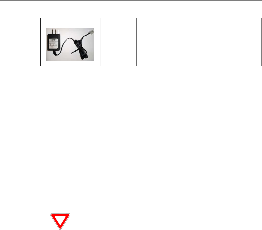
2. Plug the serial cable labeled “Console” into the COM 1 port on the PC.
Figure
3 - 2.
Serial Cable Plugged Into COM 1
Landis+Gyr
Chapter 3 - Field Configur
a
t
ion
Network Concentrator User and Installation Guide 98-1013 Rev AF 19
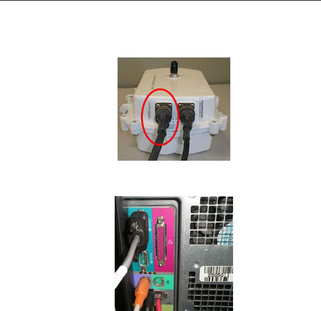
3. Navigate to Start | Accessories | Communications | Hyperterminal to launch Hyperterminal
on your PC. You must launch Hyperterminal before powering the concentrator.
Figure
3 - 3.
Launch Hyperterminal
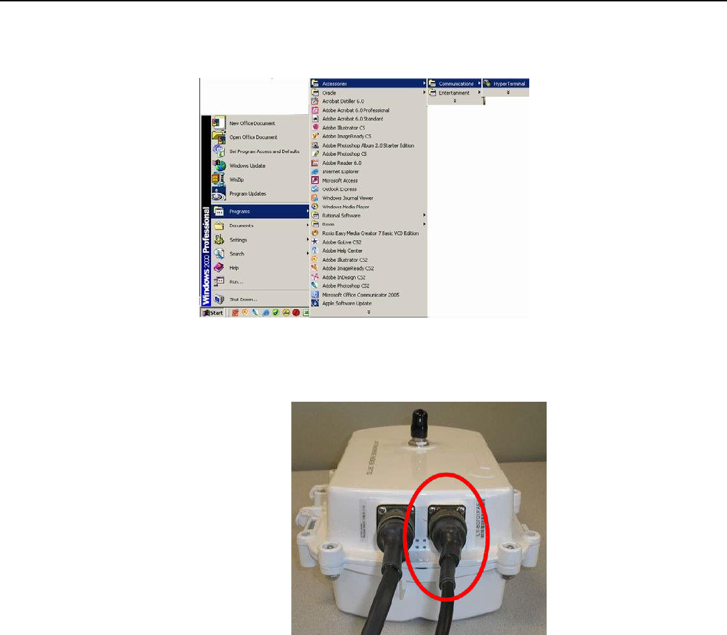
4. Connect power to the concentrator by inserting the power cable into the right barrel plug.
Figure
3 - 4.
Concentrator with programming
cable
Landis+Gyr
Chapter 3 - Field Configur
a
t
ion
Network Concentrator User and Installation Guide 98-1013 Rev AF 20
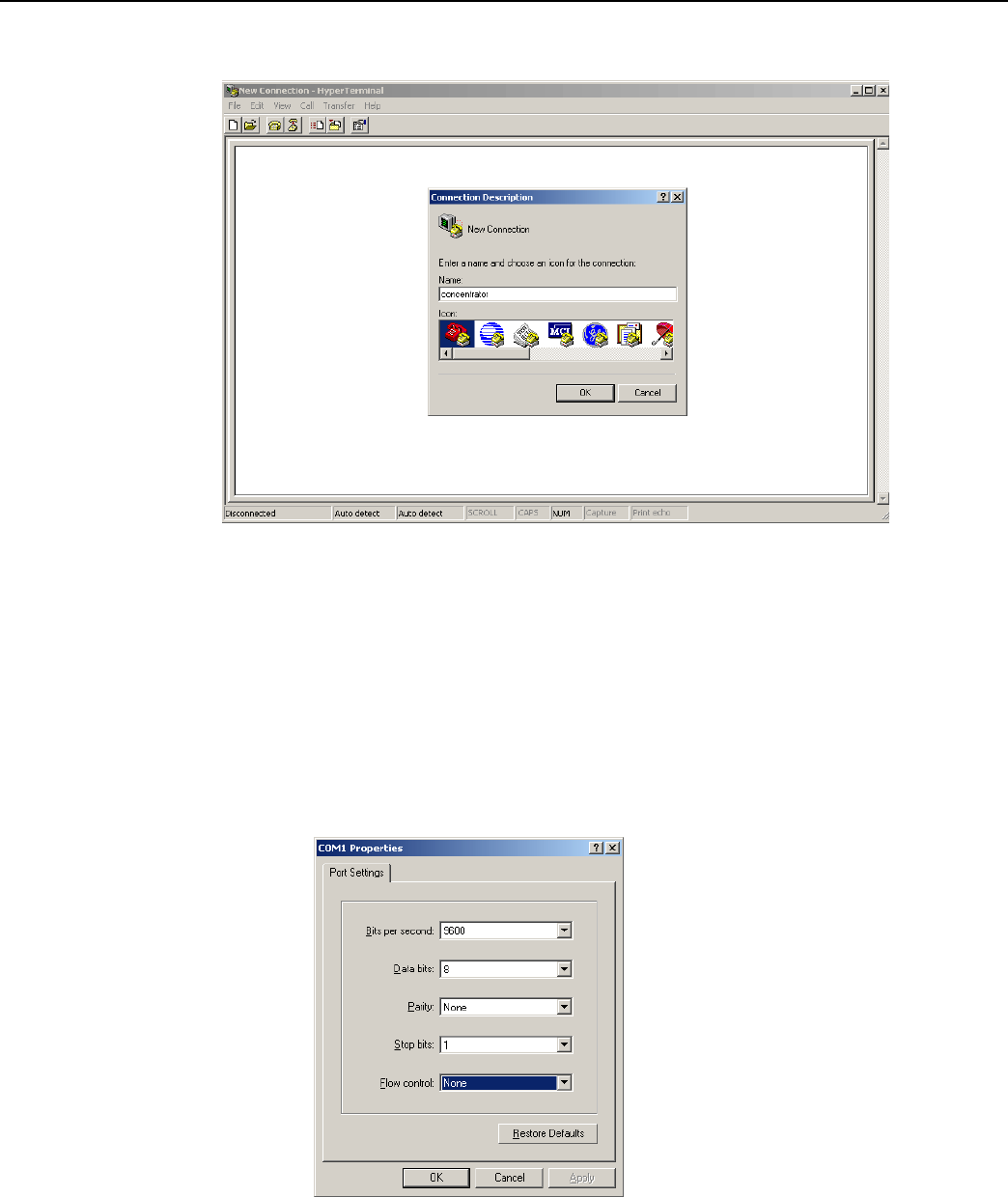
5. Name the session in Hyperterminal.
6. Click the OK button.
Figure
3 - 5.
Hyperterminal name
session
7. Verify port settings and click the OK button
• Bits per second: 9600 baud
• Data bits: 8
• Parity: None
• Stop bits: 1
• Flow control: None.
Figure
3 - 6. Set
COM
1
Properties
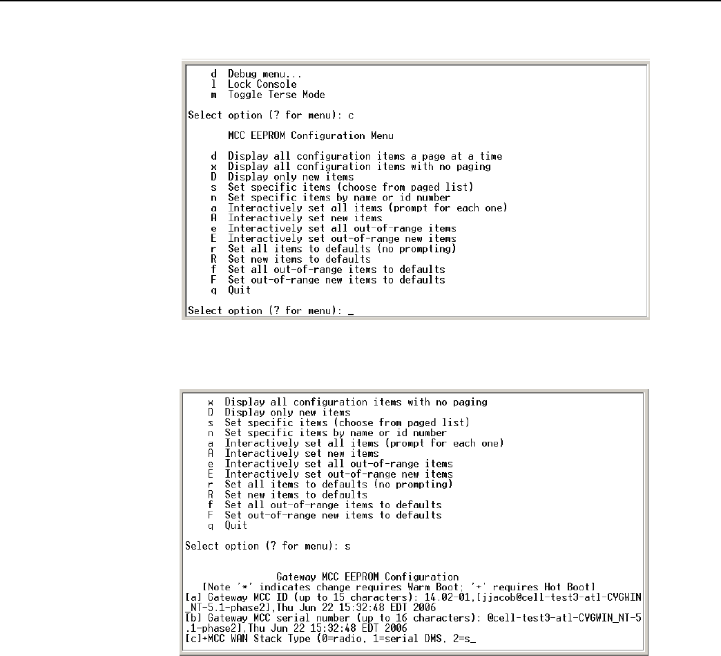
8. Type ? to access the menu.
Landis+Gyr
Chapter 3 - Field Configur
a
t
ion
Network Concentrator User and Installation Guide 98-1013 Rev AF 21
9. Type c for configuration.
Figure
3 - 7.
Type
“c” For
Configuration
10. Type s for set specific items.
Figure
3 - 8.
Type
“s” to Set
Specific Items
11. Reset values by typing the letter in Hyperterminal corresponding to the item, then updating the
value. For more information, see Sample Survey Sheet. Update the following items:
A. [d]*Gateway MCC DMS Net Address
[1..4294967039;default=4294967038]:
100051
Input the assigned Concentrator ID here.
B. [e]*Gateway MCC DMS node address (normally 1)
C.
[1..65534;default=65534]:
1
This value is always 1.
D. [f]+Log manager's (and CTS's) DMS Net Address [1..4294967039;default=4294967039]:
20
Input the assigned Net ID.
Landis+Gyr
Chapter 3 - Field Configur
a
t
ion
Network Concentrator User and Installation Guide 98-1013 Rev AF 22
E. [g]+Log manager's (and CTS's) DMS node address
[1..65534;default=65534]:
152
Input the assigned Node ID.
F. [h]+Event manager's DMS Net Address
[1..4294967039;default=4294967039]:
20
Input the assigned Net ID again.
G. [i]+Event manager's DMS node address
[1..65534;default=65534]:
152
Input the assigned Node ID again.
H. [m]*Minutes from GMT (0=GMT, 480=PST) [positive increments of 60] [-
720..720;default=480]: 420
Input the minutes from GMT.
I. [n]*Daylight savings type (0=none, 1=USA, 7=UK) [0..7;default=1]: 1
This value is always 1.
12. After you change the value, press the TAB key to refresh the page.
13. Press the Enter key to go to the next page.
14. Update the following field:
A. [e]+Lan Tx address for this MCC (0 = no Tx) [default=0]: 0
Always start with the number 400 (unless the concentrator address is 5 digits, then start with
4000), then append the concentrator ID.
For example, if the concentrator ID is 100016, then the Lan Tx address is 400100016.
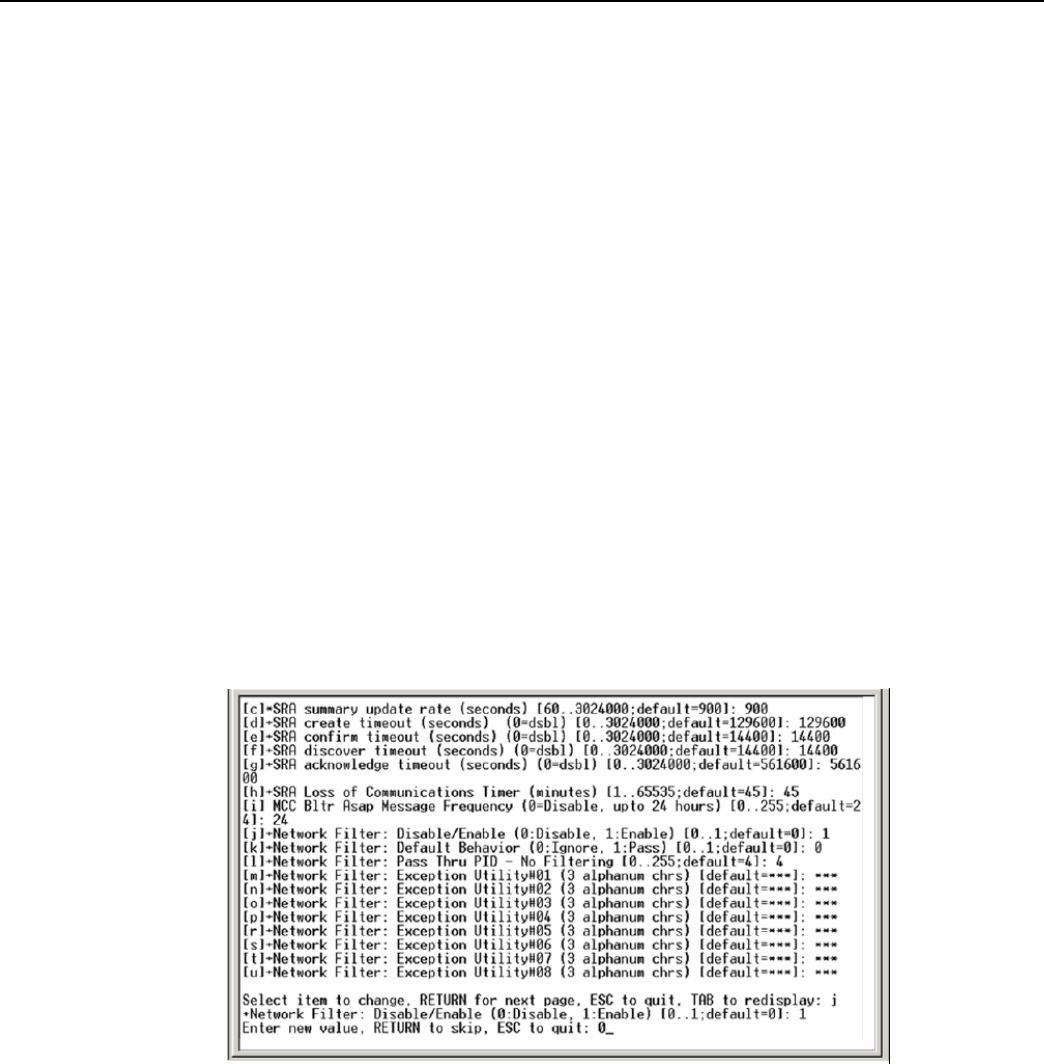
15. Press the Enter key until you see a list of Network Filter configuration items.
.
Figure
3 - 9.
Type
“0”
For Disable
16. Type the letter J for Network Filter: Disable/Enable option.
17. Type 0 to disable network filtering, and then press [Enter]
18. Press the Escape key.
Landis+Gyr
Chapter 3 - Field Configur
a
t
ion
Network Concentrator User and Installation Guide 98-1013 Rev AF 23
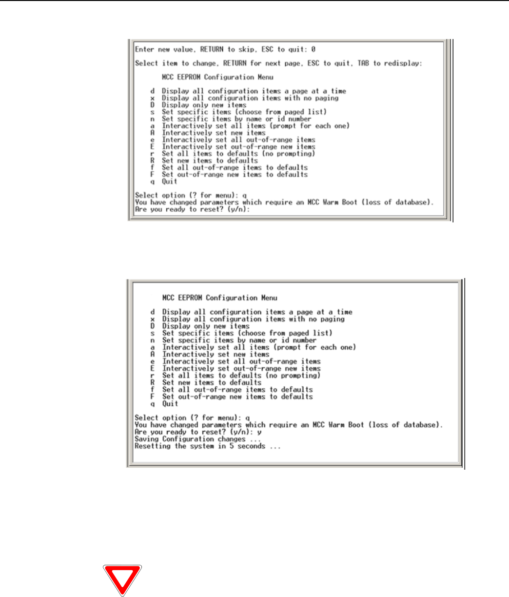
19. Type q for quit.
20. Type y for yes.
Figure
3 - 10.
Type
“q”
For
Quit
Figure
3 - 11.
Rebooting
the
concentrator
via Hyperterminal
21. After the concentrator resets, close Hyperterminal.
22. Unplug the cable marked “Console” from COM 1.
23. Plug the Lan Protocol cable into COM 1.
If you disconnect the power cables before the programming cable, the unit uses
battery backup. This depletes the battery and can affect
r
o
u
t
in
g.
Landis+Gyr
Chapter 3 - Field Configur
a
t
ion
Network Concentrator User and Installation Guide 98-1013 Rev AF 24
Disabling Network Filtering
With network filtering, you can configure the concentrator to accept all Cellnet packets, block
certain packets, or allow only certain packets. When another Cellnet customer is nearby, set your
network not to pick up the other utility’s one-way reads.
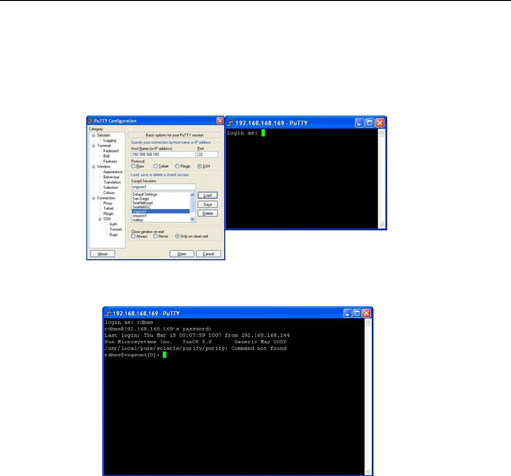
1. Connect to the host via Putty or a similar telnet client.
Figure
3 - 12.
Login using telnet client
2. Login as rdbms using password cellnet.
Figure
3 - 13.
Login
as
rdbms user
Landis+Gyr
Chapter 3 - Field Configur
a
t
ion
Network Concentrator User and Installation Guide 98-1013 Rev AF 25
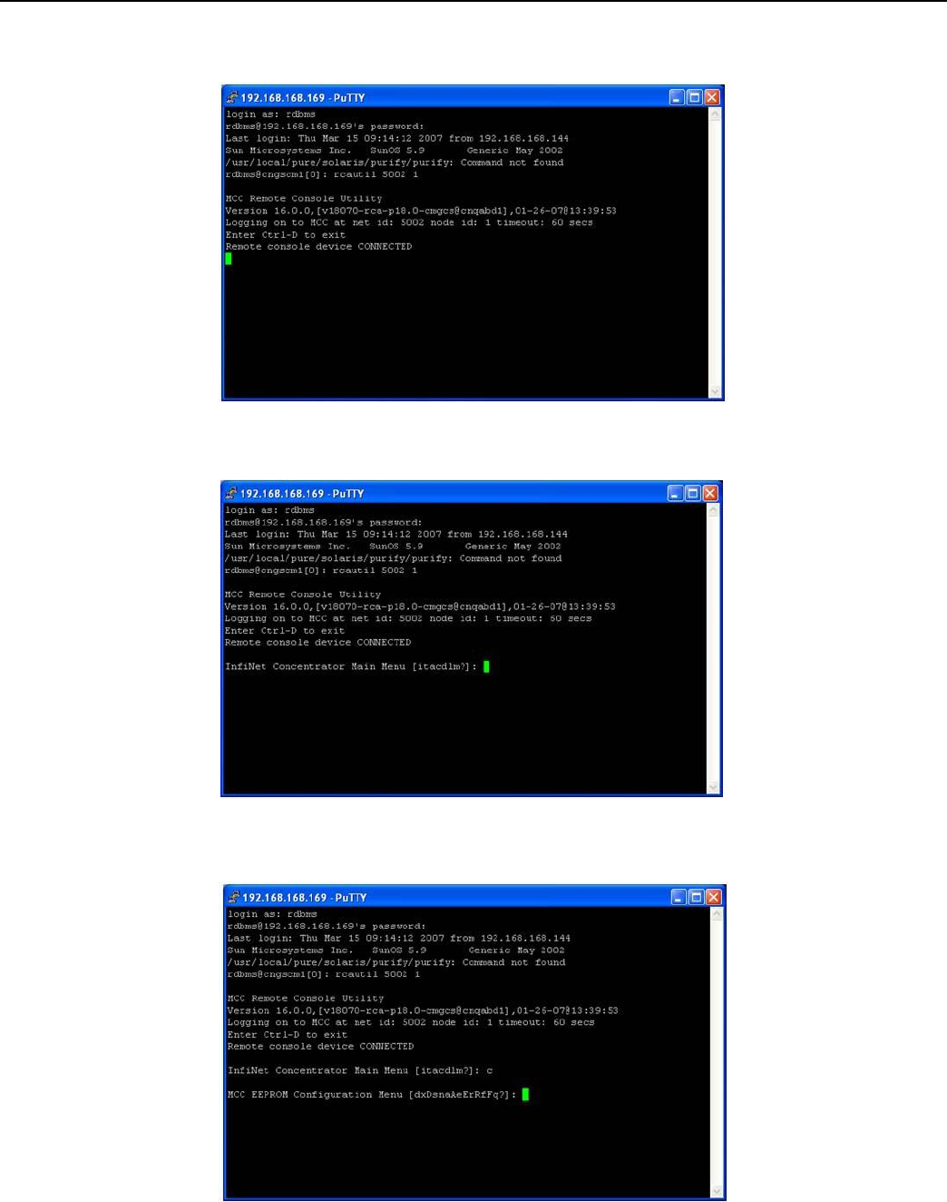
3. Use the command rcautil xxxx 1 to log into the concentrator with id xxxx.
Example: rcautil 5002 1
Figure
3 - 14.
Login
to
concentrator
4. After the screen displays “Remote console device CONNECTED”, press [Enter].
Figure
3 - 15.
Open console menu remotely
5. Type the letter c. The EEPROM configuration menu displays.

Landis+Gyr
Chapter 3 - Field Configur
a
t
ion
Network Concentrator User and Installation Guide 98-1013 Rev AF 26
Figure
3 - 16.
EEPROM Menu
Landis+Gyr
Chapter 3 - Field Configur
a
t
ion
Network Concentrator User and Installation Guide 98-1013 Rev AF 27
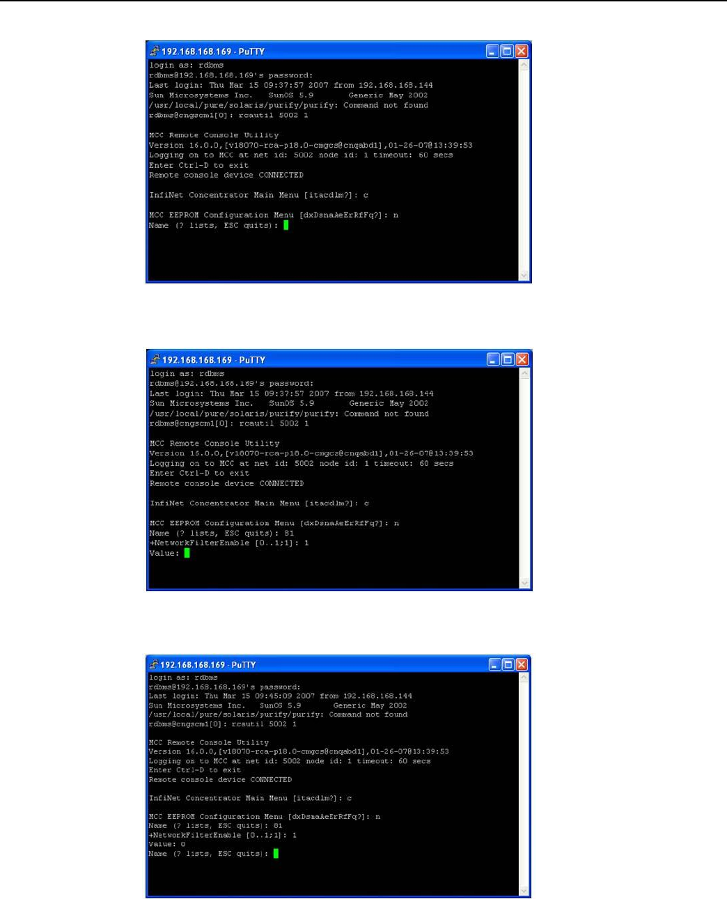
6. Type the letter n. The system prompts for a name.
Figure
3 - 17.
Name prompt
7. Type 81 to access the network filtering menu and press [Enter].
Figure
3 - 18.
Type 81
8. The default network filtering value is 1.To disable network filtering, type 0 and press [Enter]
Figure
3 - 19.
Network Filtering value
Landis+Gyr
Chapter 3 - Field Configur
a
t
ion
Network Concentrator User and Installation Guide 98-1013 Rev AF 28
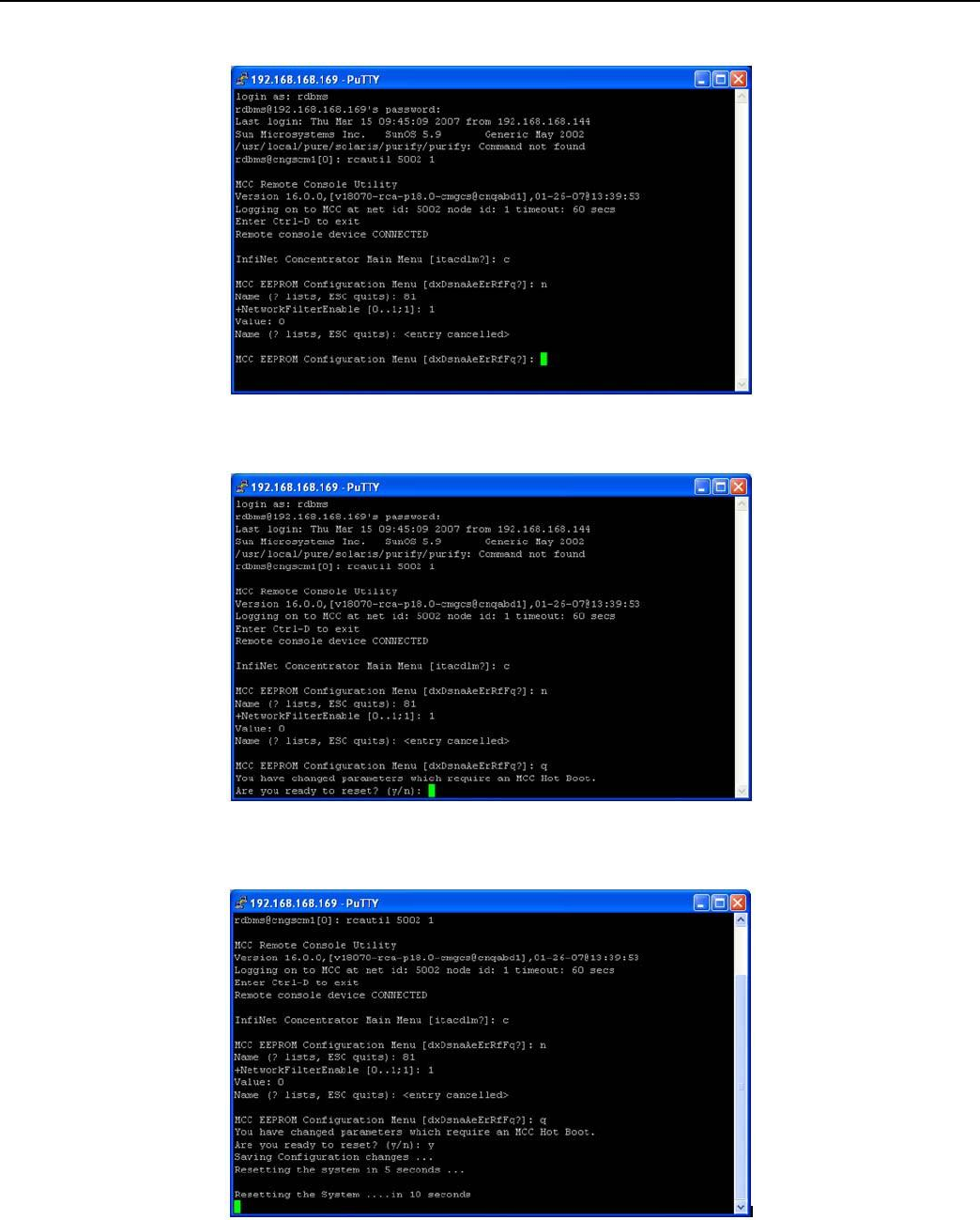
9. Type [Esc]. The EEPROM configuration menu re-displays.
Figure
3 - 20.
Return
to
EEPROM menu
10. Type the letter q. The system prompts you to hot boot the concentrator.
Figure
3 - 21.
Hot boot prompt
11. To save changes, type y. The hot boot begins.
Figure
3 - 22.
Hot boot

Landis+Gyr
Chapter 3 - Field Configur
a
t
ion
Network Concentrator User and Installation Guide 98-1013 Rev AF 29
You have now successfully disabled network filtering in this concentrator. Repeat the steps for every
concentrator in your network.

Network Concentrator User and Installation Guide 98-1013 Rev AF 30
4
Concentrator Installation
Antenna Mounting Options
The concentrator requires three antennas to communicate with the endpoints and to relay
information from the endpoint to the host application:
• Two LAN antennas
• One WAN antenna
The LAN antennas mount on the side of the antenna bracket. The WAN communications antenna
mounts on top of the enclosure or on the antenna bracket, or you can mount all three antennas
remotely from the concentrator such as at the top of a utility pole or a building parapet. If all three
antennas are mounted above the enclosure, coaxial cable connects the enclosure and the remote
antennas.
Use only Cellnet-approved antennas.
For All Installations
Concentrator Installation Sheet
The utility provides a concentrator Installation Sheet for every concentrator to be installed. The sheet
contains:
• Street address
• Type of mounting (wood pole, streetlight pole, building, etc.)
• Access method (bucket truck or climbed manually).
Power Requirements
Power requirements are listed in Performance. Verify that the power source is either 120 VAC or
240 VAC single phase.
Landis+Gyr
Chapter 4 - Concentrator Installation
Network Concentrator User and Installation Guide 98-1013 Rev AF 31
Power Cable Preparation
You can use the following AC power cable options with any Cellnet mounting kits. Cable part
numbers are:
Table 4-1. AC Power Cable Options
Part Number
Part Description
19-2271
Cable, Power, 10 foot, Utilinet, Water Block
19-2272
Cable, Power, 30 foot, Utilinet, Water Block
19-2273
Cable, Power, 4 foot, Utilinet, Water Block
19-2274
Cable, Power, 18 foot, Utilinet, Water Block
19-1192
Cable Assy, Street Light, Utilinet, 18 ft
103826-000
Cable, Assy, Street Light, UtiliNet, 4 ft
105627-000
POWER CABLE, 2 WIRE, 10 FT, 10 AWG
105627-001
POWER CABLE, 2 WIRE, 30 FT, 10 AWG
Depending on the utility requirements, physical connections to the secondary may carry additional
requirements.
Use the unterminated wires from the end of the power cable and securely attach them to the AC
power feed. Sometimes, a secondary circuit from an adjacent pole is necessary to provide
concentrator power.
Consult Appendix H for critical power connection details.
Adding Drip Loops to Cables
For any cables in an assembly, allow some slack to rest below metal parts. The slack is called a “drip
loop” and isolates rain and condensation water from the cable connections to avoid damaging
associated mechanical equipment.
Figure
4 - 1.
Cable with drip
loop

Landis+Gyr
Chapter 4 - Concentrator Installation
Network Concentrator User and Installation Guide 98-1013 Rev AF 32
Kit Part Numbers
Different kinds of installs may require different mounting and install kits. The following table
contains a list of part numbers (PN) by install type. This document details each kit in the appropriate
install description.
Table 4-2. Mounting and Programming Kits
Kit Number
Wood Pole Install
Light Pole
Horizontal
Mount
Install
Metal Pole
Vertical Mount
Install
Mounting Kit
PN 45-1048
x
Mounting Kit
PN 45-1050, 8”
rod
x
Mounting Kit
PN: 45-1049
x
Mounting Kit
PN: 45-1055, 12”
rod
x
Programming Kit
PN 45-1046
x
x
x
For information about installation types not listed here, contact Landis+Gyr Customer Operations at
ëç
äì
íáç
å
ëì
éé
çê
íK
å~]
ä~åÇ
áëÖ
ó
ê
K
Å
ç
ã
.
Landis+Gyr
Chapter 4 - Concentrator Installation
Network Concentrator User and Installation Guide 98-1013 Rev AF 33
Concentrator Assembly
Unless otherwise noted, all kits in this book are for the UtiliNet Phase II concentrator.
Table 4-3. Concentrator 26-1139
/ 26-1315
Image
Part Number
Name
Quantity
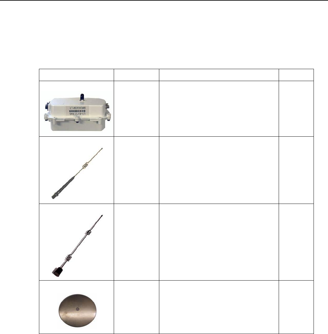
26-1139
or
26-1315
Concentrator: Series III IWR
or
Concentrator: Series IV IWR
1
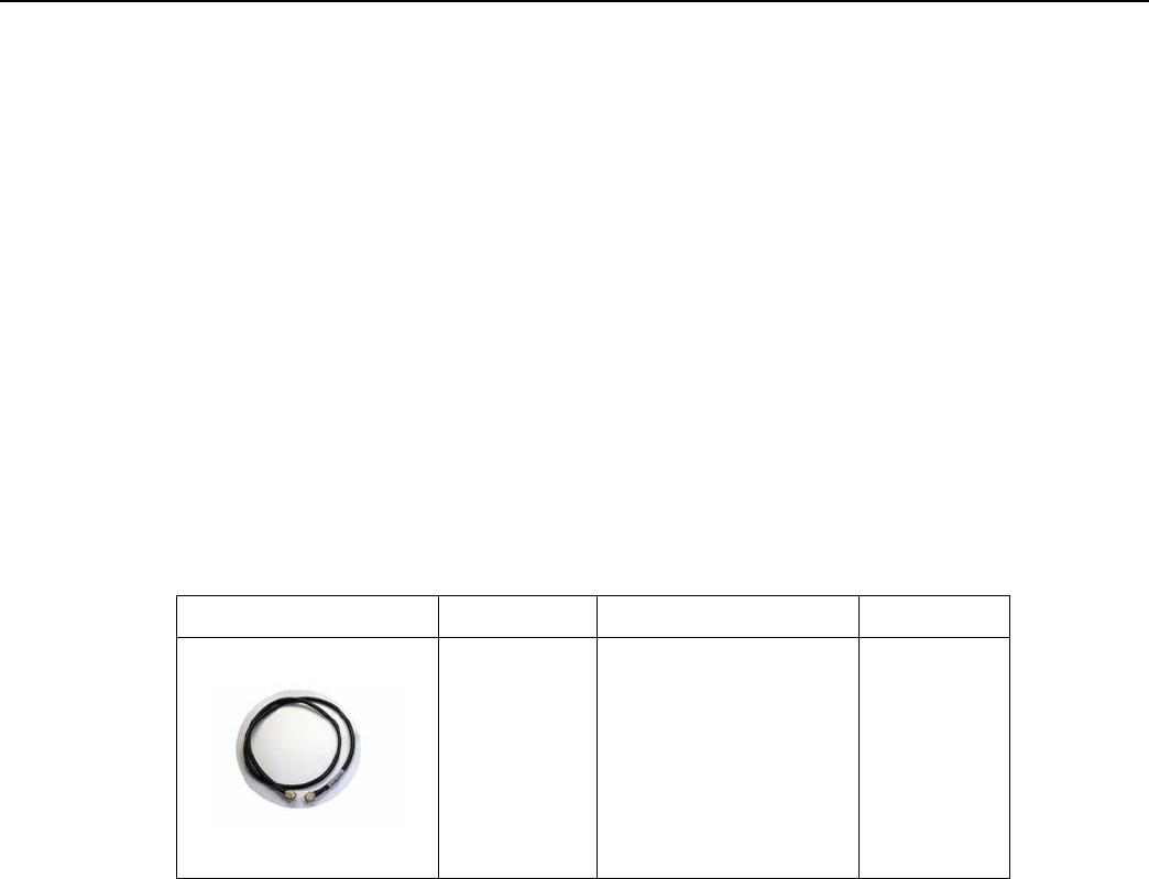
01-1239
LAN Antennas (comes
with concentrator);
2
106119-000
WAN Antenna (comes with
concentrator);
1
28-1012
Antenna Ground Plane (comes
with concentrator);
2
Optional Parts
Landis+Gyr can accommodate specialized needs such as remote antenna installation and RF filters
pre- or post-installation. An RF filter limits the device to a certain number of channels it can jump
(leaving frequencies for cell phones and pagers).
Landis+Gyr
Chapter 4 - Concentrator Installation
Network Concentrator User and Installation Guide 98-1013 Rev AF 34
Built-In RF Filter Kit
If you would like to install a concentrator with the RF Filter kit already built in, the product number
is 26-1162. Parts are the same as the regular concentrator, but this concentrator has an RF filter
installed during manufacturing. 26-1315 Concentrators contain Series IV IWRs, and these units have
the RF filter integrated into the IWR.
Additional RF Filter for Post-Installation
If you would like to add an RF Filter to a concentrator that has already been installed, use RF filter
installation kit PN 01-1018.
Remote Antenna Cable
If you need to install antennas remotely from the concentrator, there is a cable designed specifically
for this purpose
Table 4-4. Remote Antenna Cable
Image
Part Number
Description
Qty
19-2200
CBL
ASSY,REMOTE
ANT,5 FT,N
0
Ref only
Wood Pole Mount Installation
The utility or municipality determines the final guidelines of where to install the concentrator. Know
and follow the utility or municipality guidelines before installing the concentrator and antennas.
Landis+Gyr
Chapter 4 - Concentrator Installation
Network Concentrator User and Installation Guide 98-1013 Rev AF 35
Wood Pole Mounting Kit
In addition to your chosen concentrator assembly kit, you need a mounting kit.
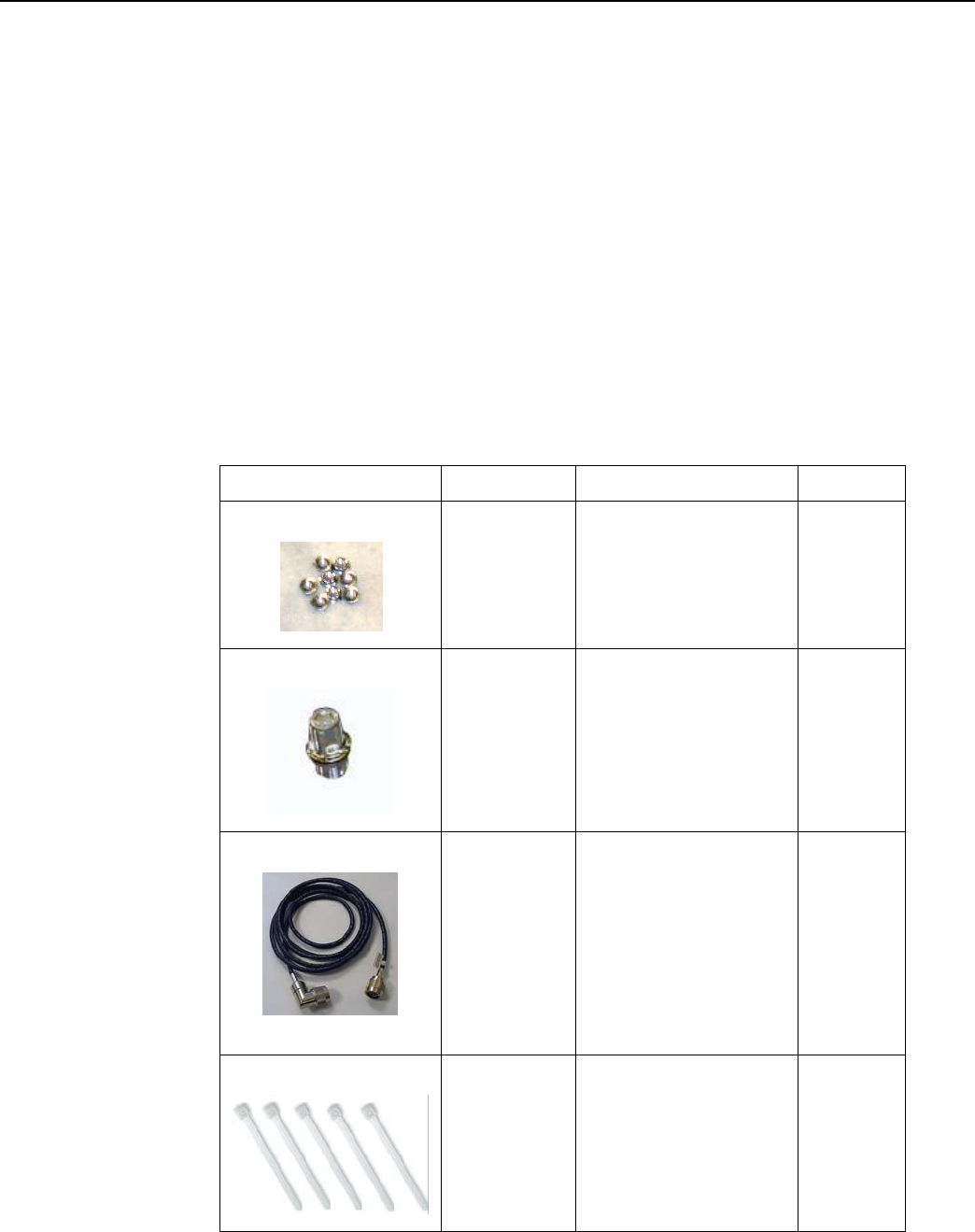
Table 4-5. 45-1048
KIT, MOUNTING,WOOD POLE, CONCENTRA
T
OR
Image
Part
Number
Name
Quant
ity
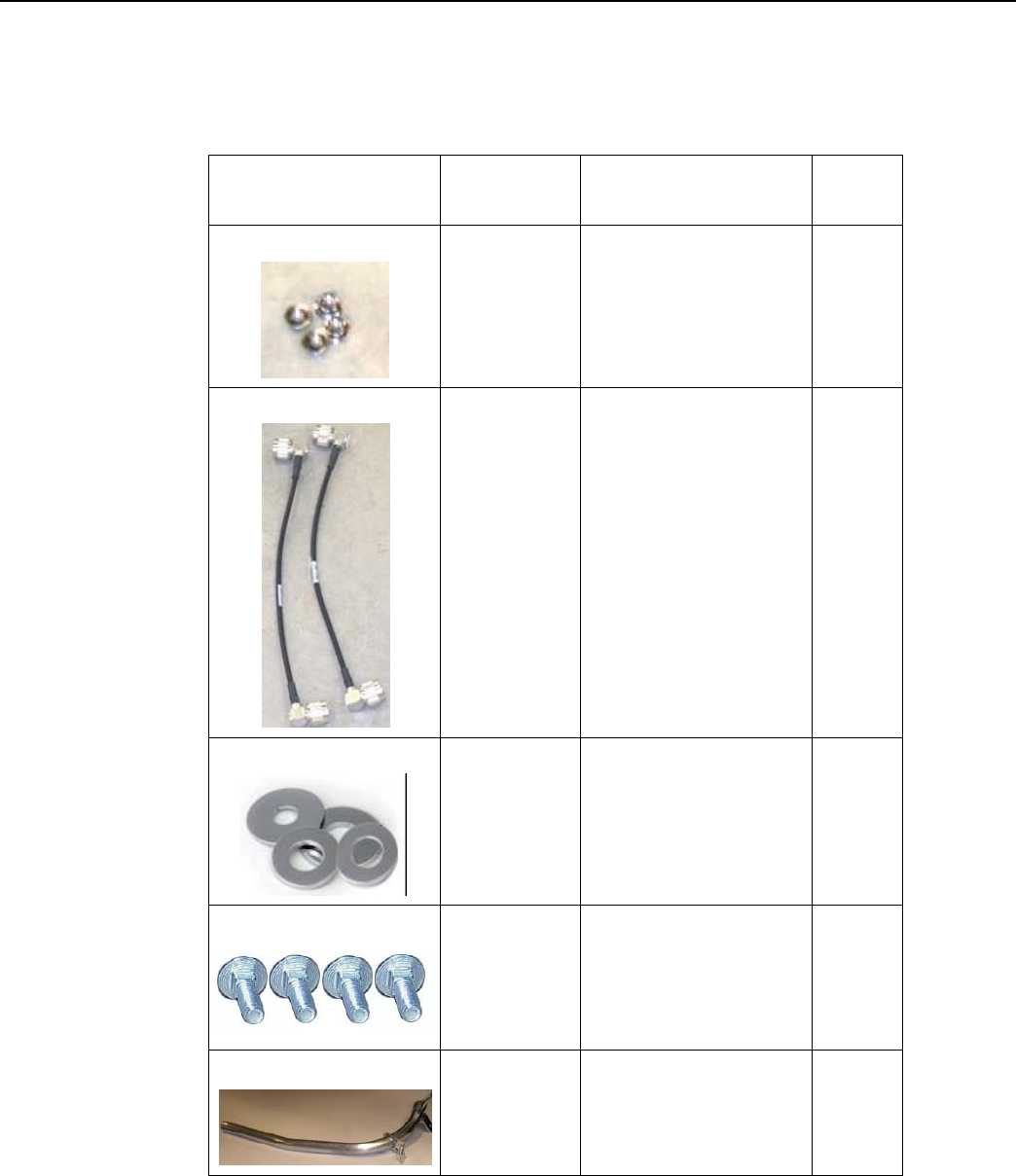
101983-025
NUT, HEX, FLANGE 1/
4-20UNC, SS
4
19-1013
1 foot
CBL ASSY,
REMOTE
ANTENNA
2
22-0421
WASHER,1/4 FLAT,1/
16 THK,SS
4
22-1071
BOLT, CARR., 1/4-20
UNC-2A X 4.00, SS
4
28-1299
Bracket, Wood Pole,
Alum, concentrator,
Enhanced
Processor
1
Landis+Gyr
Chapter 4 - Concentrator Installation
Network Concentrator User and Installation Guide 98-1013 Rev AF 36
Wood Pole Installation
Pr
ocedur
e
.
Figure
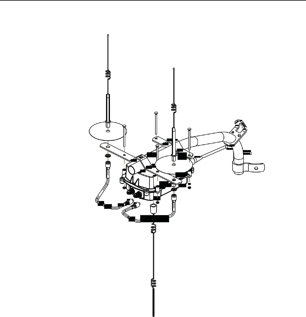
4 - 2.
Built-out wood mounted concentrator assembly illustration, side and front
views
Landis+Gyr
Chapter 4 - Concentrator Installation
Network Concentrator User and Installation Guide 98-1013 Rev AF 37
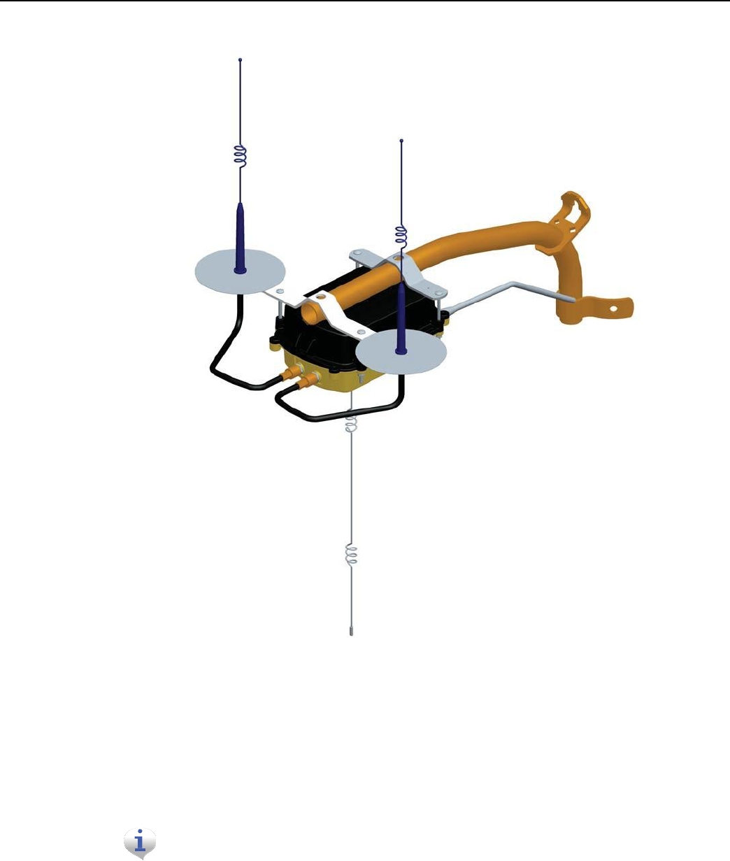
Figure
4 - 3.
Built-out wood mounted concentrator assembly illustration, view from
top
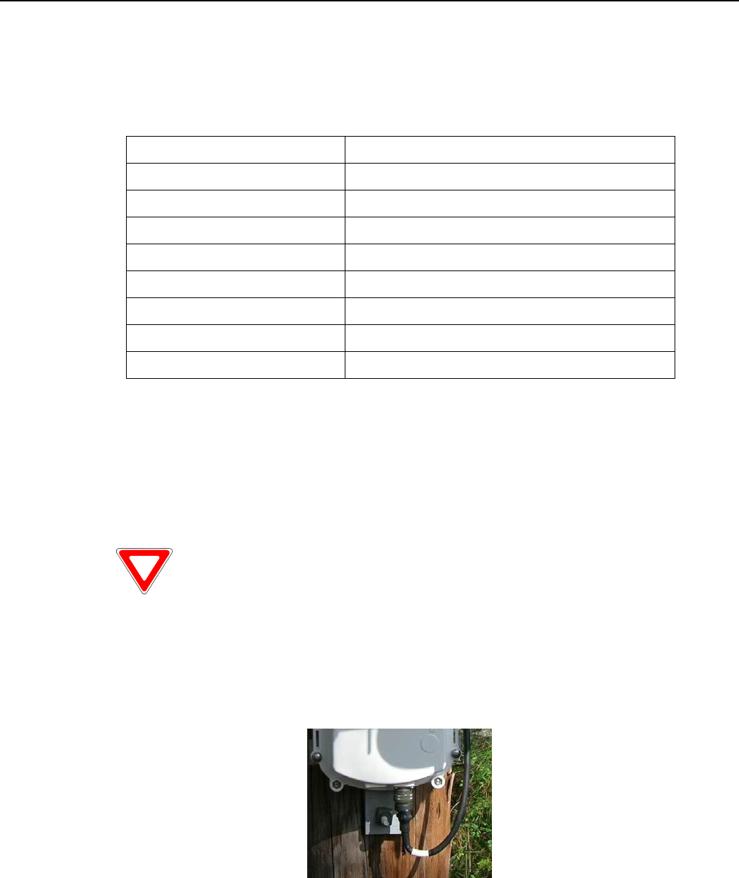
1. Affix the mounting bracket (PN 28-1147) to the wood pole using two mounting bolts (D/A
Bolts) with washer and nut or steel bands. (Hardware parts not included in kit.)
2. Attach the concentrator to the bracket, being aware to face the military connectors toward the
pole. Using the four (4) carriage bolts, secure it with nuts and washers included in the kit.
3. Connect the LAN antennas to the bracket.
Ground planes are built into bracket PN 28-1147. Do not install
a
ddit
i
on
al
ground planes to a mounting that uses this bra
c
k
e
t.
4. Using the RF cables, connect the LAN antennas to the concentrator.
5. Attach the WAN antenna to the concentrator directly.
Landis+Gyr
Chapter 4 - Concentrator Installation
Network Concentrator User and Installation Guide 98-1013 Rev AF 38
6. Attach the AC power cable to the concentrator. Use any of the approved power cable options.
Metal Pole vertical Mount Installation
The utility or municipality determines the final guidelines of where to install the concentrator. Know
and follow the utility or municipality guidelines before installing the concentrator and antennas.
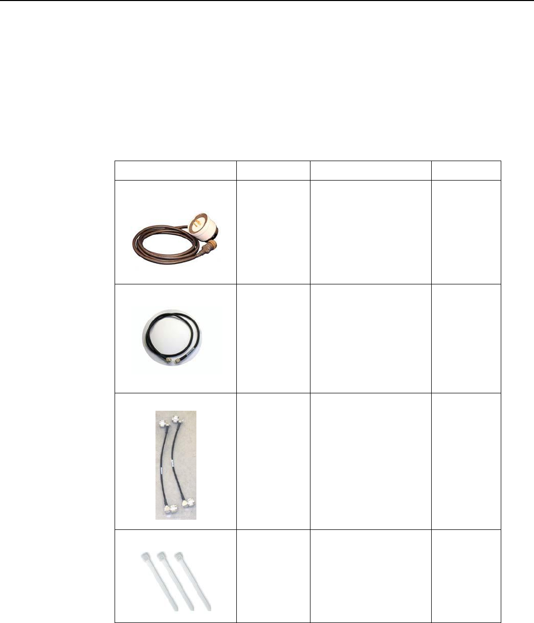
Concentrator Metal Pole Mounting Kit
In addition to your chosen concentrator assembly kit, you need a mounting kit
• Kit number 45-1050 includes 8” rods for poles 3.5” to 5”.
• Kit number 45-1055 includes 12” rods for poles 5” to 7.5”.
These kits are identical except for the rod length, so only kit number 45-1050 is described below.
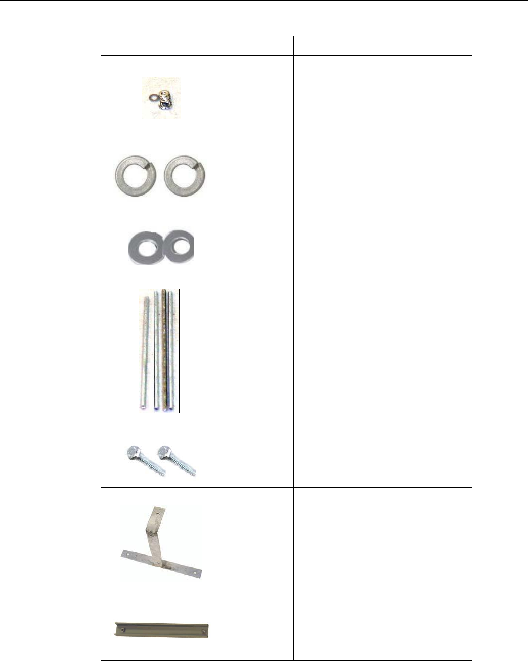
Table 4-6. 45-1050
KIT, MOUNTING, LIGHT POLE, CONCENTRA
T
OR
Image
Part Number
Name
Quantity
101983-025
NUT, HEX, FLANGE 1/4-
20UNC, SS
8
16-0214
CONN, BULKHEAD, F/
F, TYPE N
1
19-2215
CBL
ASSY,CYLINK
MALE-MAL E B,B
5.5 feet
3
22-0375
TIE WRAP, 28
INCH, NYLON,
WHITE
5
Landis+Gyr
Chapter 4 - Concentrator Installation
Network Concentrator User and Installation Guide 98-1013 Rev AF 39
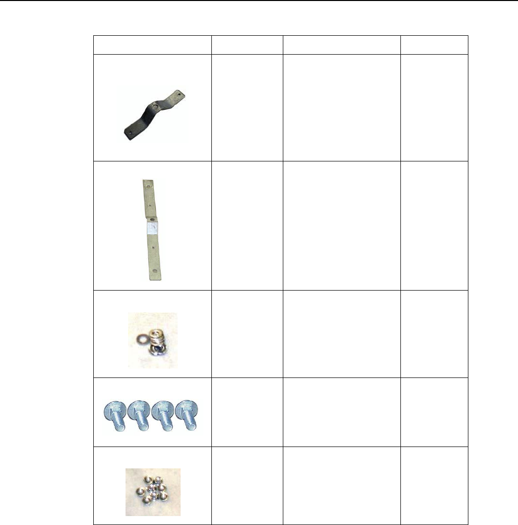
Table 4-6. 45-1050
KIT, MOUNTING, LIGHT POLE, CONCENTRATOR
(continued)
Image
Part Number
Name
Quantity
22-0421
WASHER,1/4 FLAT,1/16
THK,SS
8
22-0453
WASHER, 3/8
SPLIT LOCK, S S
2
22-0587
WSHR FLT, 3/8 INCH 1
INCHOD.4381ID,
300 S
S
2
22-1062
ROD,THREADED,1/4-
20X8IN, S S
4
22-2319
SCREW, 3/8-
16X7/8, HEX CAP,
SS
2
28-1090
BRACKET,ANTENNA,
LIGHT POLE, 16 INCH
1
28-2315
BRACKET, POLE,
STRAP MOUNT
1
Landis+Gyr
Chapter 4 - Concentrator Installation
Network Concentrator User and Installation Guide 98-1013 Rev AF 40
Table 4-6. 45-1050
KIT, MOUNTING, LIGHT POLE, CONCENTRATOR
(continued)
Image
Part Number
Name
Quantity
28-1061
BRKT, MOUNTING, 3
TO 5 IN POLE,
WANGATE S2
BLT3
2
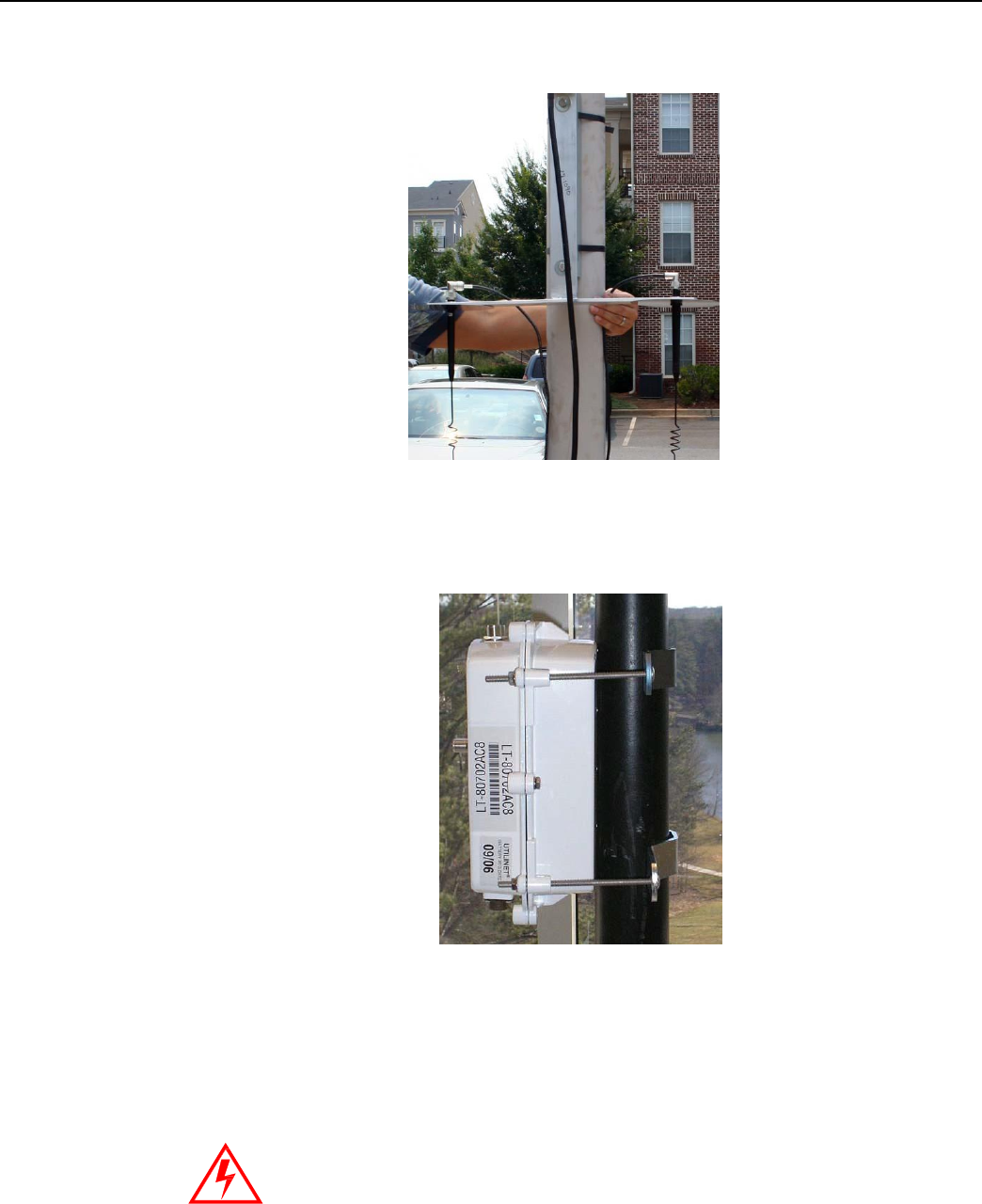
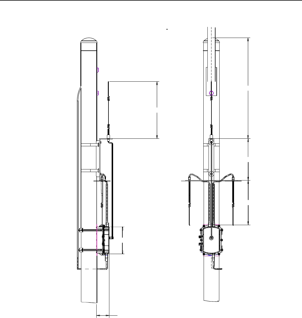
Metal Pole Installation
Pr
ocedur
e
This section describes the light pole installation procedure.
The photos in this section are for illustrative purposes only. In the field, mount
brackets higher on the pole. Use the parts supplied in the
kit
.
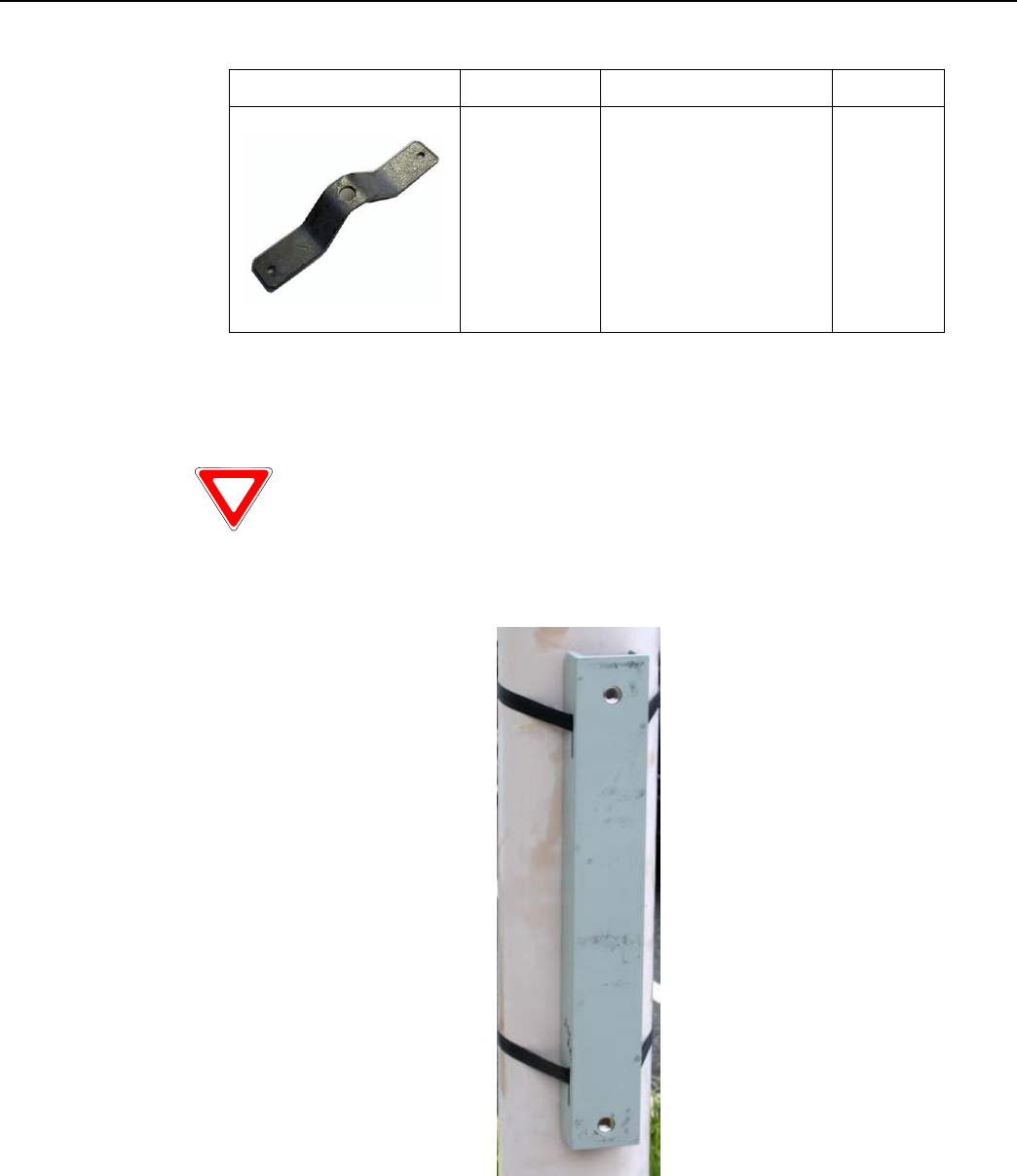
1. Attach the strap mount pole bracket (PN 28-2315) to the pole using steel bands.
Figure
4 - 4.
Strap mount pole bracket attached
to pole
Landis+Gyr
Chapter 4 - Concentrator Installation
Network Concentrator User and Installation Guide 98-1013 Rev AF 41
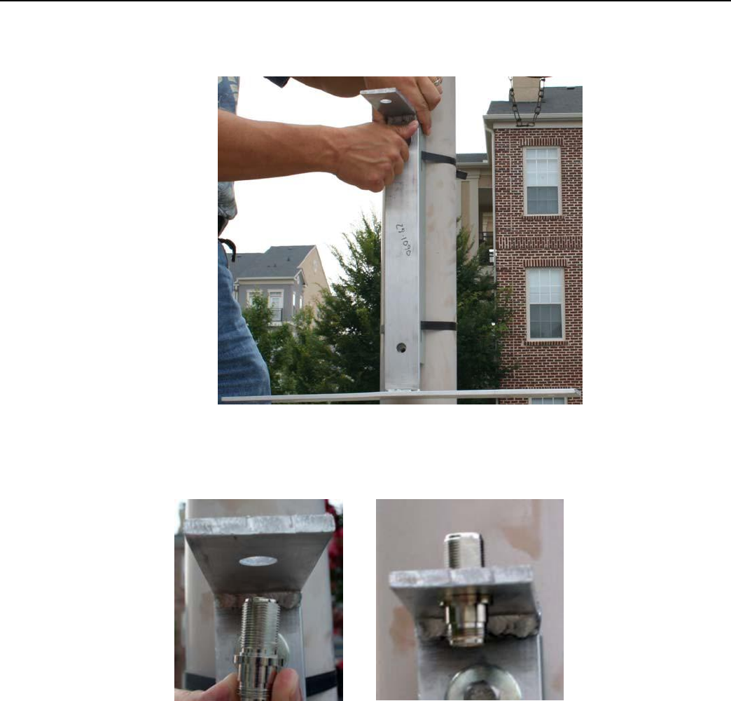
2. Attach the antenna light pole bracket (PN 28-1090) to the strap mount pole bracket. Torque to
200 in/lbs.
Figure
4 - 5.
Antenna light pole bracket attached
to
mounting bracket
3. Install the bulkhead connector (PN 16-0214). Torque to 100 in/lbs.
Figure
4 - 6.
Attaching bulkhead connector
Landis+Gyr
Chapter 4 - Concentrator Installation
Network Concentrator User and Installation Guide 98-1013 Rev AF 42
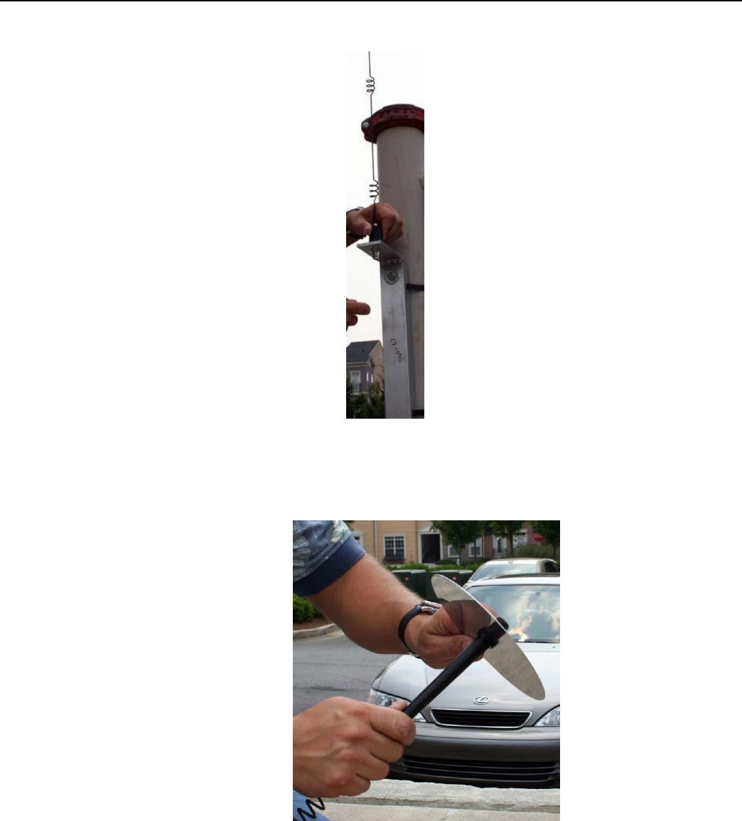
4. Connect the WAN antenna.
Figure
4 - 7.
Connecting
the
WAN antenna
5. Put the ground plane on the LAN antennas.
Figure
4 - 8.
Putting ground plane
on
antennas
Landis+Gyr
Chapter 4 - Concentrator Installation
Network Concentrator User and Installation Guide 98-1013 Rev AF 43
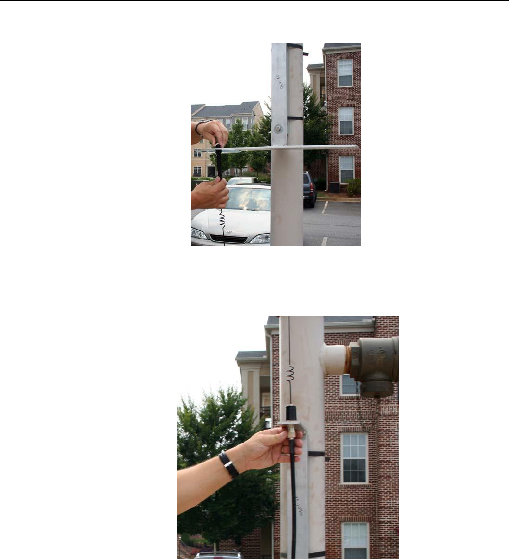
6. Connect the LAN antennas to the antenna light pole bracket. Torque to 90 in/lbs.
Figure
4 - 9.
Connecting
a
LAN antenna
7. Attach the RF cables to the WAN antenna.
Figure
4 - 10.
Attaching
RF
cable
Landis+Gyr
Chapter 4 - Concentrator Installation
Network Concentrator User and Installation Guide 98-1013 Rev AF 44
8. Attach the right-angle end of the cable to the top of the LAN antennas.
Figure
4 - 11.
Attaching right-angle end
of
cable
9. With the mounting kit, affix the concentrator and two brackets sandwiched on the pole down
from the light arm using the supplied hardware.
Figure
4 - 12.
Concentrator mounted
10. Attach the AC power cable to the concentrator using one of the power cable options. Leave slack
in the cable to form a drip loop.
If
using
the 105704-000, 105704-001, 105704-002, or 105704-003 cables, the
end of the cable opposite the connector (the unterminated end) must be
installed in a junction box or other suitable enclosure.
Leaving the end of the cable exposed may allow water to migrate into
th
e
cable and into the Concentra
t
or.
See
Appendix
H for power cable installation procedures and details.
Landis+Gyr
Chapter 4 - Concentrator Installation
Network Concentrator User and Installation Guide 98-1013 Rev AF 45
TBD
22.15
16.25
TBD
10.48
4.90
(REF)
Figure
4 - 13.
Complete pole mount
assembly
Landis+Gyr
Chapter 4 - Concentrator Installation
Network Concentrator User and Installation Guide 98-1013 Rev AF 46
Streetlight Arm Horizontal Mount Installation
The utility or municipality determines the final guidelines of where to install the concentrator. Know
and follow the utility or municipality guidelines before installing the concentrator and antennas.
Concentrator Streetlight Arm Mounting Kit
In addition to your chosen concentrator assembly kit, you need a mounting kit.
Table 4-7. 45-1049
KIT, HORIZONTAL MOUNTING,METAL POLE, CONCENTRA
T
OR
Image
Part Number
Name
Quantity
103826-000
CBL, ASSY, STREET
LIGHT, UTILINET,
4FT
0,
ref only
19-2200
CBL
ASSY,REMOTE
ANT,5 FT,N
0
Ref only
19-1013
1 foot
CBL, ASSY, Remote
Antenna
2
22-0375
TIE WRAP,
28inch, NYLON,
WHITE
3
Landis+Gyr
Chapter 4 - Concentrator Installation
Network Concentrator User and Installation Guide 98-1013 Rev AF 47
Table 4-7. 45-1049
KIT, HORIZONTAL MOUNTING,METAL POLE, CONCENTRATOR
(continued)
Image
Part Number
Name
Quantity
28-1061:AC
BRKT, MOUNTING, 3
TO 5 IN POLE,
WANGATE S2
BLT3
1
28-1031
BRKT, ANTENNA
MOUNT, 3 & 5 IN
POLE, RADIO
1
22-0421
WASHER, 1/4 FLAT, 1/
16 THK, SS
4
22-1072
BOLT, CARR, 1/4-20
UNC-2A X 6 SS
4
101983-025
NUT, HEX, FLANGE, 1/
4-2 OUNC, SS
4
Landis+Gyr
Chapter 4 - Concentrator Installation
Network Concentrator User and Installation Guide 98-1013 Rev AF 48
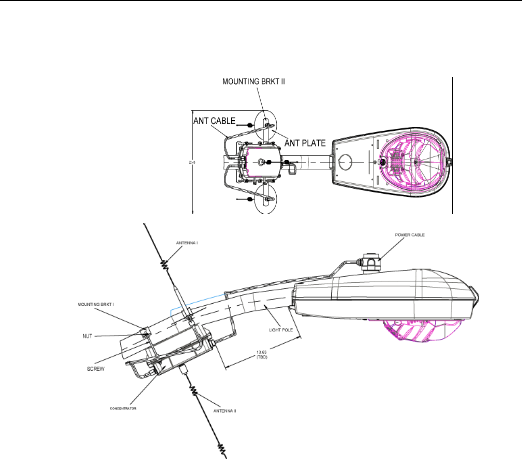
Streetlight Arm Installation
Pr
ocedur
e
.
Figure
4 - 14.
Pole mounted concentrator assembly
illustration
Install the concentrator approximately 18" below the lowest portion on the light head arm.
1. Thread the four rods through the two included metal brackets.
2. Hold the concentrator on the front of the pole while threading the rods through the enclosure
from the back of the pole.
3. Place nuts and washers on the four threaded rods and tighten until secure.
4. Assemble the antennas, ground planes, and RF cables. Leave slack in the cables to form a drip
loop.
5. To connect the adapter, remove the photocell on the existing light head.
6. Install the adapter.

Landis+Gyr
Chapter 4 - Concentrator Installation
Network Concentrator User and Installation Guide 98-1013 Rev AF 49
7. Lock it into place by turning clockwise.
8. Re-install the photocell in the same manner.
9. Run the cable between the brackets and the concentrator enclosure.
10. Using the supplied UV rated tie wraps, secure the cable to the light head.
11. Connect the power plug to the bottom of the concentrator.
If you need a longer cable, you can build one using one of the approved AC
power cables and a photocell power adapt
e
r.
Network Concentrator User and Installation Guide 98-1013 Rev AF 50
5
RF Filter and Battery
Replacement Kits
You can retrofit a concentrator with an RF Filter anytime. This chapter outlines the parts and
procedure to perform this task. It also outlines the battery replacement kit and procedure.
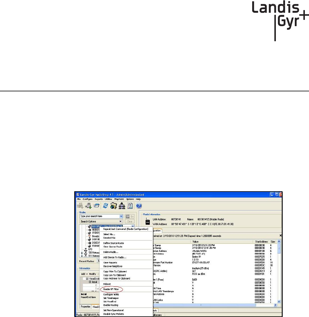
Enable/Disable RF Filter
When an optional RF filter has been included for reducing interference, the filter can be enabled or
disabled in the field by qualified personnel using RadioShop 4.1.
1. Verify that the Router is highlighted on the Nodes Pane.
2. Right-click the Router ID.
3. Select Enable RF Filter from the pop-up menu.
To Disable the RF Filter
Figure
5 - 1.
Enable
(or
Disable)
the RF Filter
4. Right-click the Router ID.
5. Select Disable RF Filter from the pop-up menu.
Landis+Gyr
Chapter 5 - RF Filter and Battery Replacement Kits
Network Concentrator User and Installation Guide 98-1013 Rev AF 51
Retrofitting a Series III Concentrator with an RF Filter
You can add an RF filter to a concentrator after you have installed it in the field. Use kit number 45-
1053.
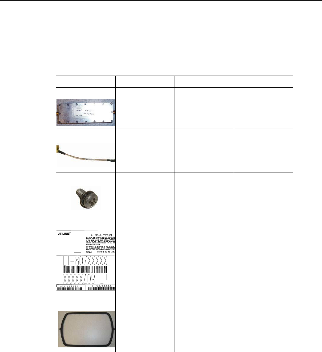
Table 5-1. RF Filter Retrofit Kit
45-1053
Image
Part Number
Part Name
Quantity
01-1018
FILTER,
EXTERNAL RF,
S3 IWR
1
19-1070
CBL ASSY, RF TO
FILTER,
WANGATE S3
1
22-1049
SEMS,2-56x3/
16inch,INT,PNH,P
HH,SS
4
23-1098
Label, FCC, InfiNet
Concentrator,
Phase 2, RF
Filter
1
106555-000
GASKET UTILINET
1
Landis+Gyr
Chapter 5 - RF Filter and Battery Replacement Kits
Network Concentrator User and Installation Guide 98-1013 Rev AF 52
Performing an RF Filter Retr
ofit
1. Unbolt the base from the lid.
Figure
5 - 2. RF
Filter retrofit unbolt
lid
and base
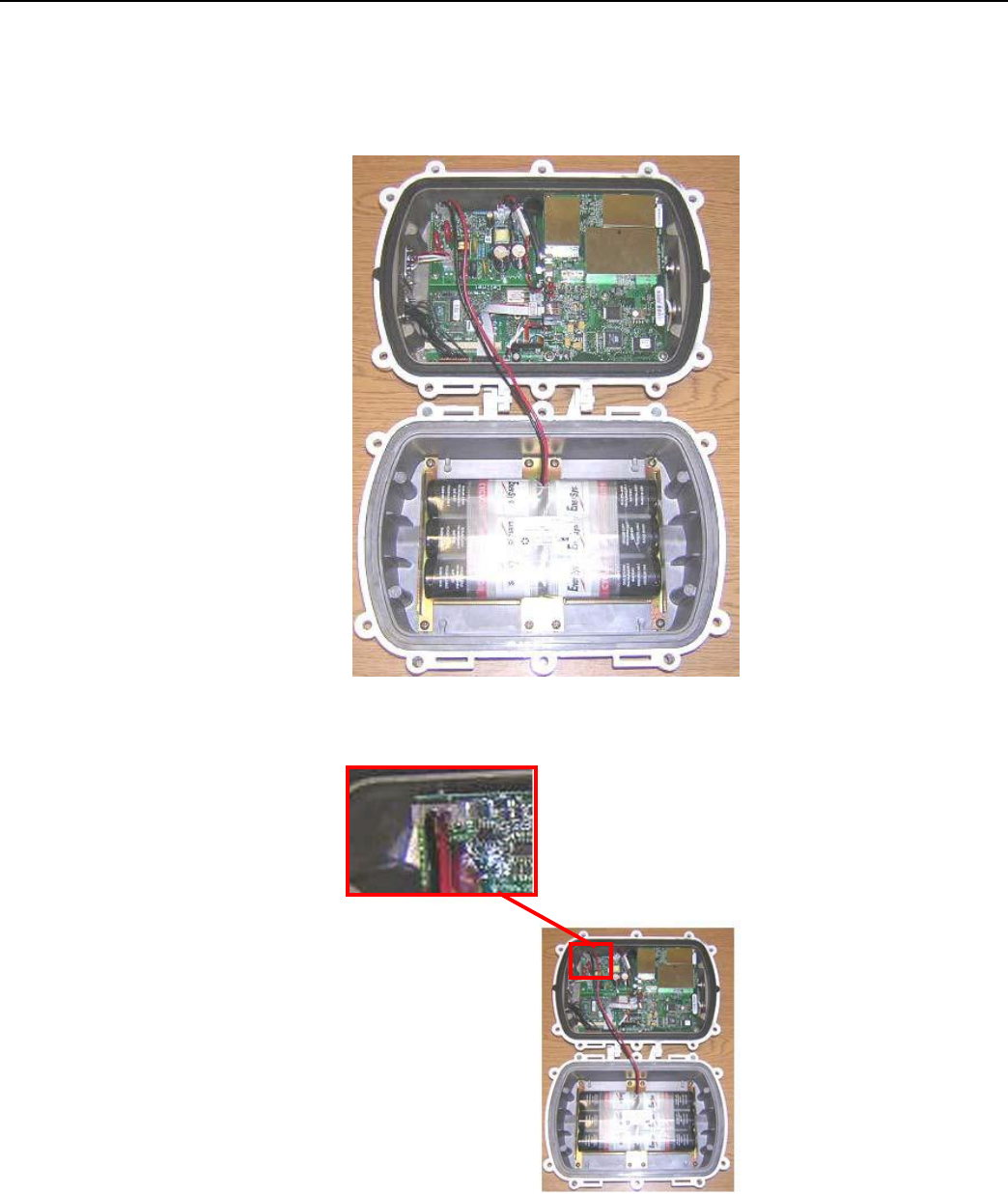
2. Disconnect the battery cable from the power supply board.
Figure
5 - 3. RF
Filter retrofit remove gasket and battery cables
3. Disconnect the lid from the base by the hinges.
4. Remove and discard the gasket.
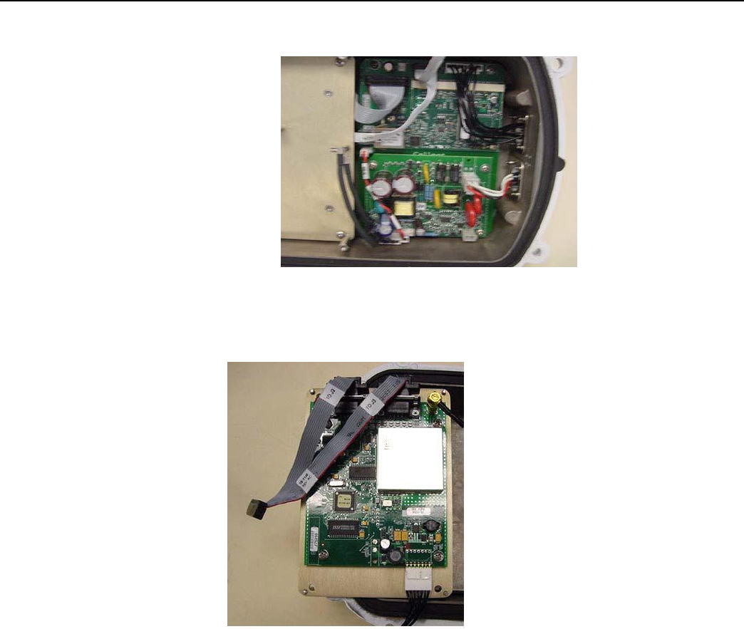
5. Disconnect the BLT power cable from the Motherboard PCBA.
6. Disconnect BLT/ConnectCore Communication Cable connection 'BLT J2' from the 'J2'
connection on BLT Transceiver PCBA.
7. Disconnect both RF Cables from 'J3' and 'J4' connectors on BLT Transceiver PCBA.
Landis+Gyr
Chapter 5 - RF Filter and Battery Replacement Kits
Network Concentrator User and Installation Guide 98-1013 Rev AF 53
8. Remove the BLT/S3 Bracket from the base.
Figure
5 - 4. RF
Filter retrofit remove BLT
bracket
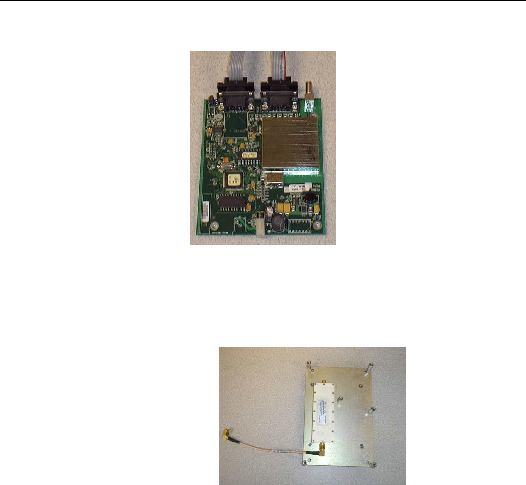
9. Disconnect RF Cable to 'J5' connection from UtiliNet S3 PCBA.
10. Disconnect power supply/S3 Cable from 'J6' connector on UtiliNet S3 PCBA.
Figure
5 - 5. RF
Filter retrofit remove UtiliNet
S3
PCBA
Landis+Gyr
Chapter 5 - RF Filter and Battery Replacement Kits
Network Concentrator User and Installation Guide 98-1013 Rev AF 54
11. Remove UtiliNet S3 PCBA from BLT/S3 Bracket.
Figure
5 - 6. RF
Filter Retrofit
12. Secure the RF Filter (PN 01-1018) to the BLT/S3 Bracket (PN 28-1084), using screws (PN 22-
1083). Torque screws to 5 ±.5 in-lbs.
13. Attach the RF Filter Cable Assembly (PN 19-1070) to the RF Filter (PN 01-1018). Torque to 7
+/-.5 in-lbs. Orient filter as shown below.
Figure
5 - 7.
Installing
RF
Filter
14. Put the concentrator back together in reverse order of the way you took it apart.
• You must use a fresh gasket (PN 106555-000, supplied with kit).
• Torque all SEM screws to 10+/-.5 in-lbs.
• Torque all SMA connector to 7+/-.5 in-lbs.
• Torque all exterior bolts to 45+/-.5 in-lbs.
Landis+Gyr
Chapter 5 - RF Filter and Battery Replacement Kits
Network Concentrator User and Installation Guide 98-1013 Rev AF 55
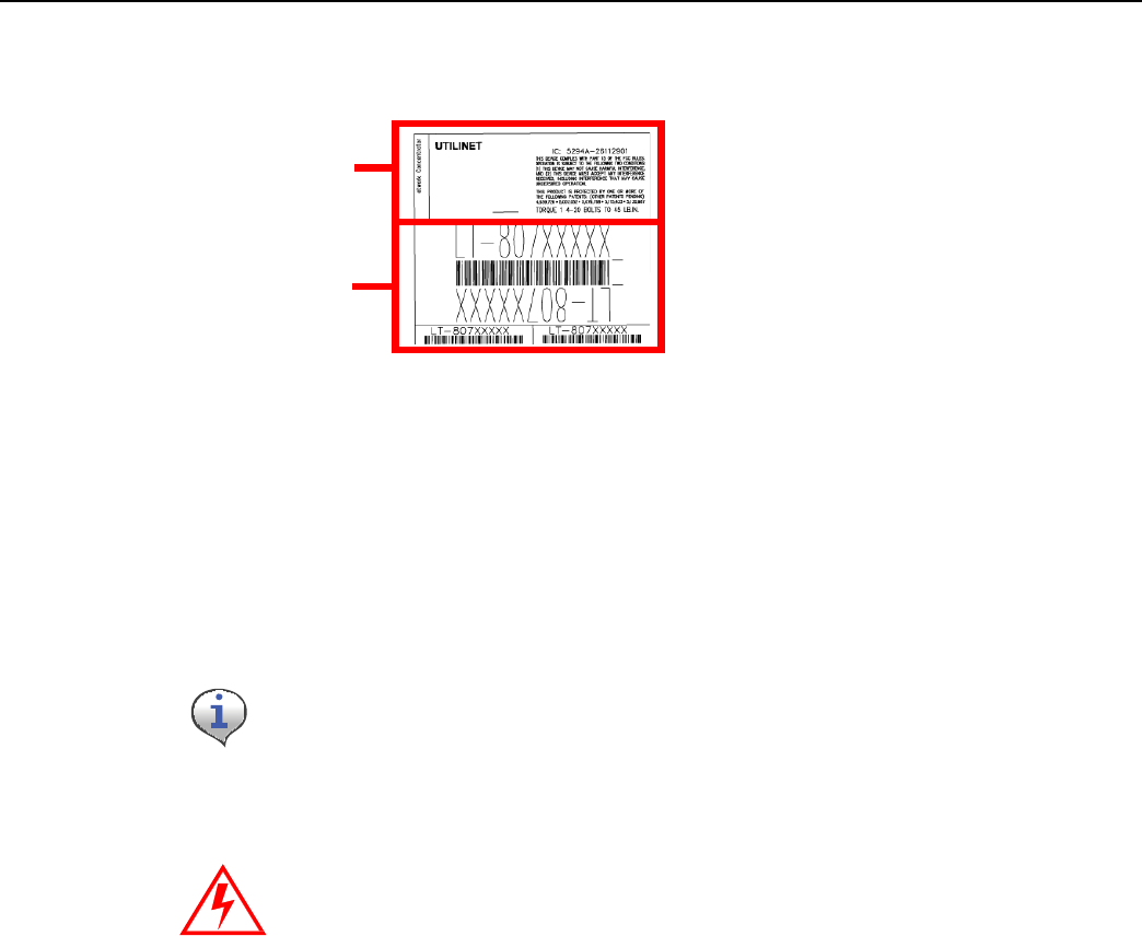
15. Replace the labels as shown:
Replace top labels
Discard serial
code labels
About Battery Storage
The ideal storage environment is normal room temperature or slightly below. Excess temperature
shortens the battery life and accelerates self discharge. Charge batteries at least once per year or
sooner if needed. The battery open circuit voltage should not be allowed to drop below 12V.
Recycle or dispose of batteries
pr
o
p
e
rly.
Do not mutilate or dispose of batteries in fire to avoid risk of releasing
toxic materials. Short-circuiting batteries may cause burns.
Battery
T
e
st
You must use a copy of RadioShop 3.4 or higher to run the battery test. See the applicable
RadioShop Getting Started Guide for information on using the application to test the concentrator
battery.
The new Autoranging power supply (25-1008 or 25-1025) can be software-enabled into battery test
mode. Disconnect the battery charger from the battery to place a load across the battery. Measure the
battery voltage before, during, and at the end of this test to discover bad or weak batteries. This test
is more effective than measuring the battery voltage without a load on the battery.
All Series III radios will have this capability. The Series II and IIb may have this capability if
retrofitted with kit, P/N 45-1029 (other kits may be available).
Landis+Gyr
Chapter 5 - RF Filter and Battery Replacement Kits
Network Concentrator User and Installation Guide 98-1013 Rev AF 56
Replacement
mater
i
als
All parts required for battery replacement should already be present at the assembly site. To replace
the battery, procure a battery pack replacement kit (PN 45-1058).
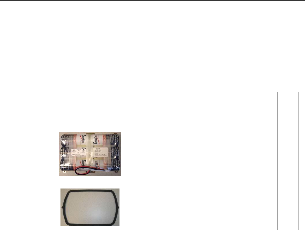
Concentrator Battery Pack Replacement Kit
Table 5-2. Battery Pack Replacement Kit
t45-1058
Image
Part Number
Part Name
Items pictured below
96-1070
Battery pack replacement kit,
Concentrator
1
01-1039
Battery pack 12V 4.5AH
1
106555-000
Gasket UtiliNet
1
Landis+Gyr
Chapter 5 - RF Filter and Battery Replacement Kits
Network Concentrator User and Installation Guide 98-1013 Rev AF 57
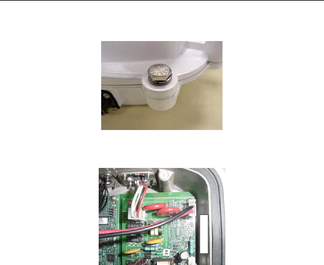
Replacing the Battery
Pack
1. Remove all six bolts and hardware that hold the enclosure base to the enclosure lid.
2. Open the unit.
Figure
5 - 8.
Open unit
3. Disconnect the battery cable from the power supply board.
Figure
5 - 9.
Battery cable closeup
Landis+Gyr
Chapter 5 - RF Filter and Battery Replacement Kits
Network Concentrator User and Installation Guide 98-1013 Rev AF 58
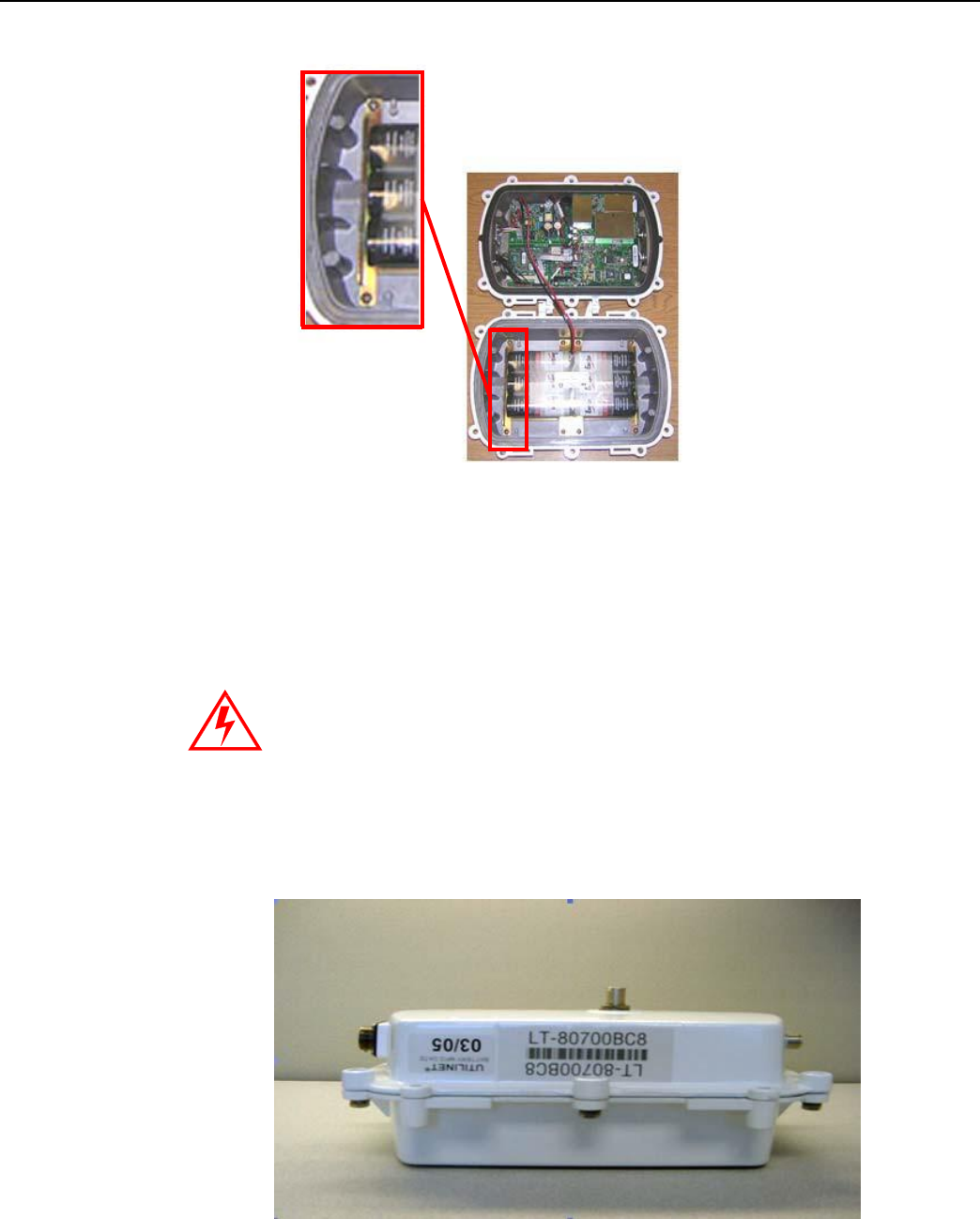
4. Remove all eight pan head screws and the battery pack.
Figure
5 - 10.
Sample Pan Head Screw
Location
5. Place the new battery pack in the enclosure base and secure it with all eight pan head screws.
6. Torque the screws to 8 ±.5 in-lbs.
7. Connect the battery cable.
8. Replace enclosure gasket (PN 106555-000) with a new gasket. Do not re-use the old gasket.
9. Attach the enclosure lid to the enclosure base.
Take care to not pinch the battery cable between the base and the lid.
Pinching
the cable can short the battery and result in a hazardous
condition.
10. Secure with all six bolts, nuts, washer-flats, and washers.
11. Torque bolts to 45 ±.5 in-lbs.
12. Affix the new battery date label to the outside of the enclosure.
Figure
5 - 11.
New battery date label affixed
to
concentrator
enclosure

Network Concentrator User and Installation Guide 98-1013 Rev AF 60
6
Performing
System
Upgrades
What Are System Upgrades?
There are three kinds of upgrades you can perform on a concentrator:
• The concentrator firmware
• The IWR radio firmware
• The IWR radio DCW.
Accessing a Concentrator for Programming
There are two ways to access a concentrator for upgrading:
• Over the air
• Directly via cable (About Programming and Diagnostic Cables, for more information).
Upgrading a Concentrator Over the Air (OTA)
You can remotely download firmware to the concentrator via a command window from your PC.
You must have control-level user access to the host to perform this procedure.
About the Image File
Landis+Gyr Customer Operations manages upgrades to firmware. Landis+Gyr notifies you when
there is a new release of firmware and makes the file available. To upgrade firmware, load the
concentrator with a new “image.bin” file. Contact Customer Operations at
ëç
äì
íáç
å
ëì
éé
çê
íK
å~]
ä~åÇ
áëÖ
ó
ê
K
Å
ç
ã
for more information or to obtain the latest version of the
firmware.
The download application utility runs on the host backend via a process called Live System update
(LSU). The host connects over the air (OTA) to the concentrator. The host automatically:
1. Sends the new firmware information to the concentrator.
2. Polls the concentrator to verify that the download is complete.
3. Disconnects when the download is complete.
Landis+Gyr
Chapter 6 - Performing System Upgrad
es
Network Concentrator User and Installation Guide 98-1013 Rev AF 61
Verifying
the Concentrator and the Host
Before sending large amounts of data over the network, verify communication with the concentrator.
Also verify that the Cellnet host is up and running. Ping the concentrator via command line
rtrping.
Concentrator addresses used in the following instructions are samples on
ly.
Obtain your utility’s concentrator addresses from Customer Operations
a
t
ëçä
ì
íáçåëìééçêíK
å~
]ä~å
ÇáëÖóê
KÅ
çã
.
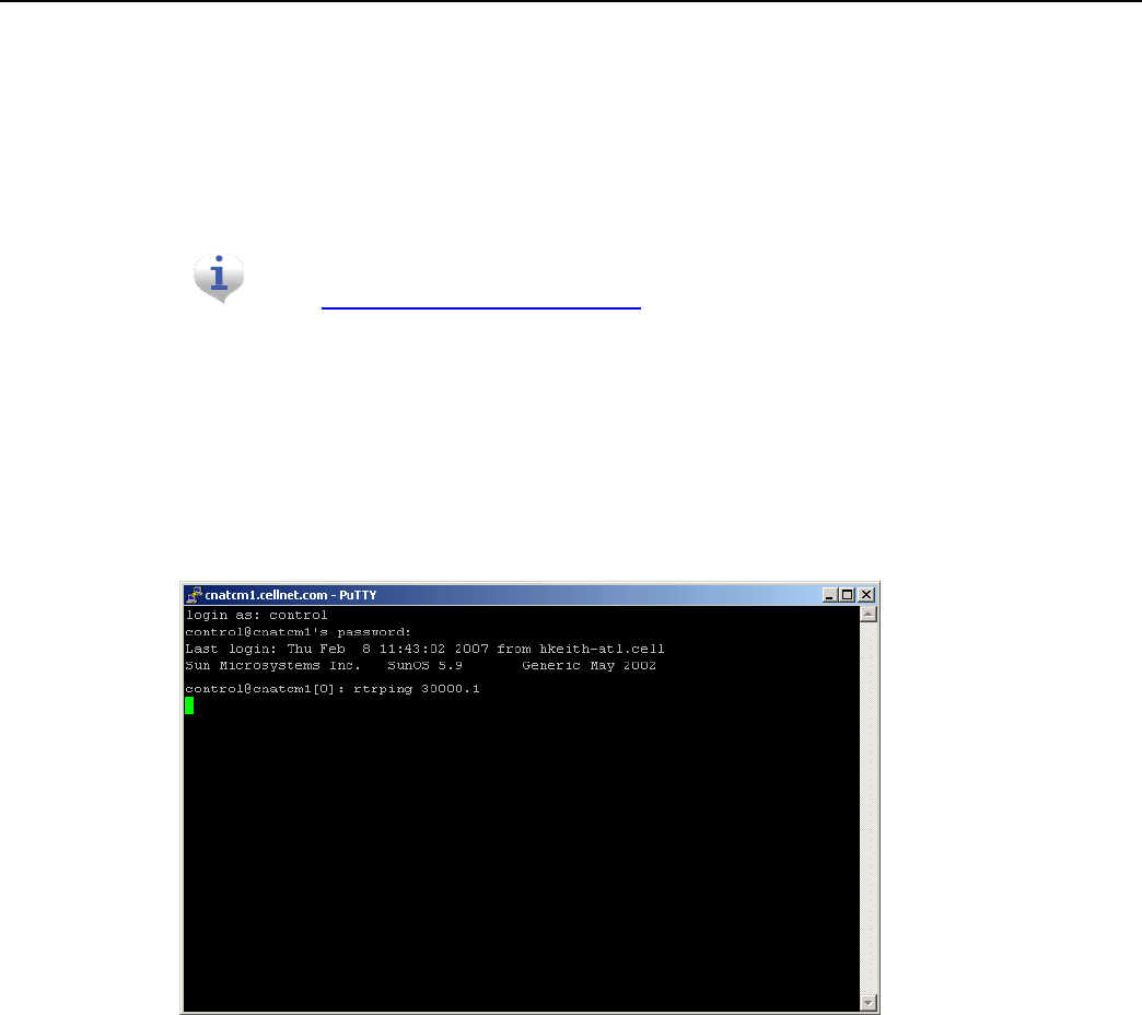
Pinging from the Command Line
You need to know the concentrator’s network ID before performing this task.
1. Open a command window on your PC.
2. Use your administrative credentials to login as control user.
3. Type rtrping [concentrator ID].
Figure
6 - 1.
rtrping screen shot
If the ping is successful, the system returns the length of time it took to receive a response. If the
ping is unsuccessful, the system indicates a time out condition.
Verifying
Host Operations
Verify that the Cellnet system is running.
1. Open a command window on your PC.
2. Use your administrative credentials to login as control user.
Landis+Gyr
Chapter 6 - Performing System Upgrad
es
Network Concentrator User and Installation Guide 98-1013 Rev AF 62
3. Type iscellnet.
Figure
6 - 2.
iscellnet screen shot
If the ping is successful, the system returns the length of time it took to receive a response. If the
ping is unsuccessful, the system indicates a time out condition.
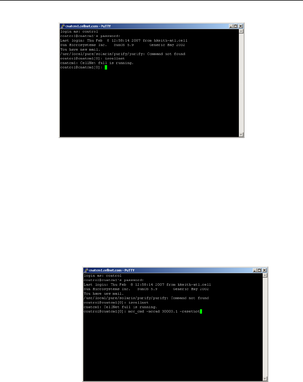
Hot-Booting a Concentrator
Always perform a disconnect, followed by a hot boot, before any download operations. For a
firmware upgrade to be successful, it must load on top of system variables set to their default values.
If you always perform a hot reboot, you always start with default values.
1. Open a command window on your PC.
2. Use your administrative credentials to login as control user.
3. Type mcc_cmd 30000.1 -resethot.
Figure
6 - 3.
Hot boot
concentrator
Landis+Gyr
Chapter 6 - Performing System Upgrad
es
Network Concentrator User and Installation Guide 98-1013 Rev AF 63
Downloading Firmware OTA
The download client program offers several command line options you can use to manage the
upgrade process. These options are listed in Table 6-1 on page 65. Mandatory download options
include: -mccadd, -session, and -s (image file location).
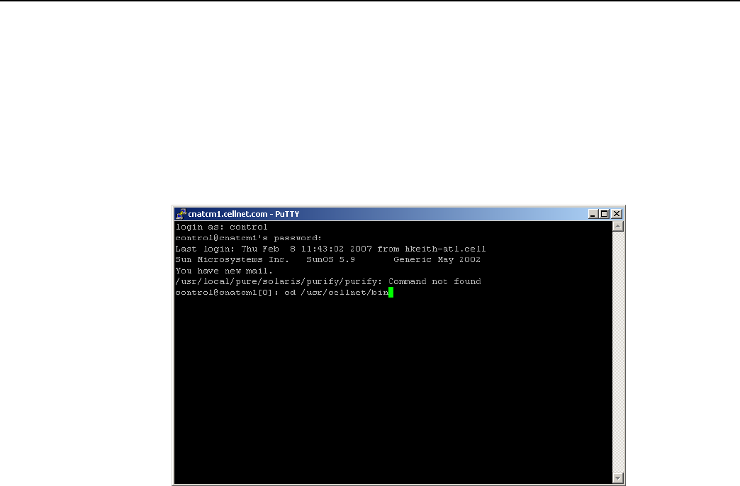
1. Open a command window on your PC.
2. Use your administrative credentials to login as control user.
3. Browse to /usr/cellnet/bin.
Figure
6 - 4. cd usr/cellnet/bin
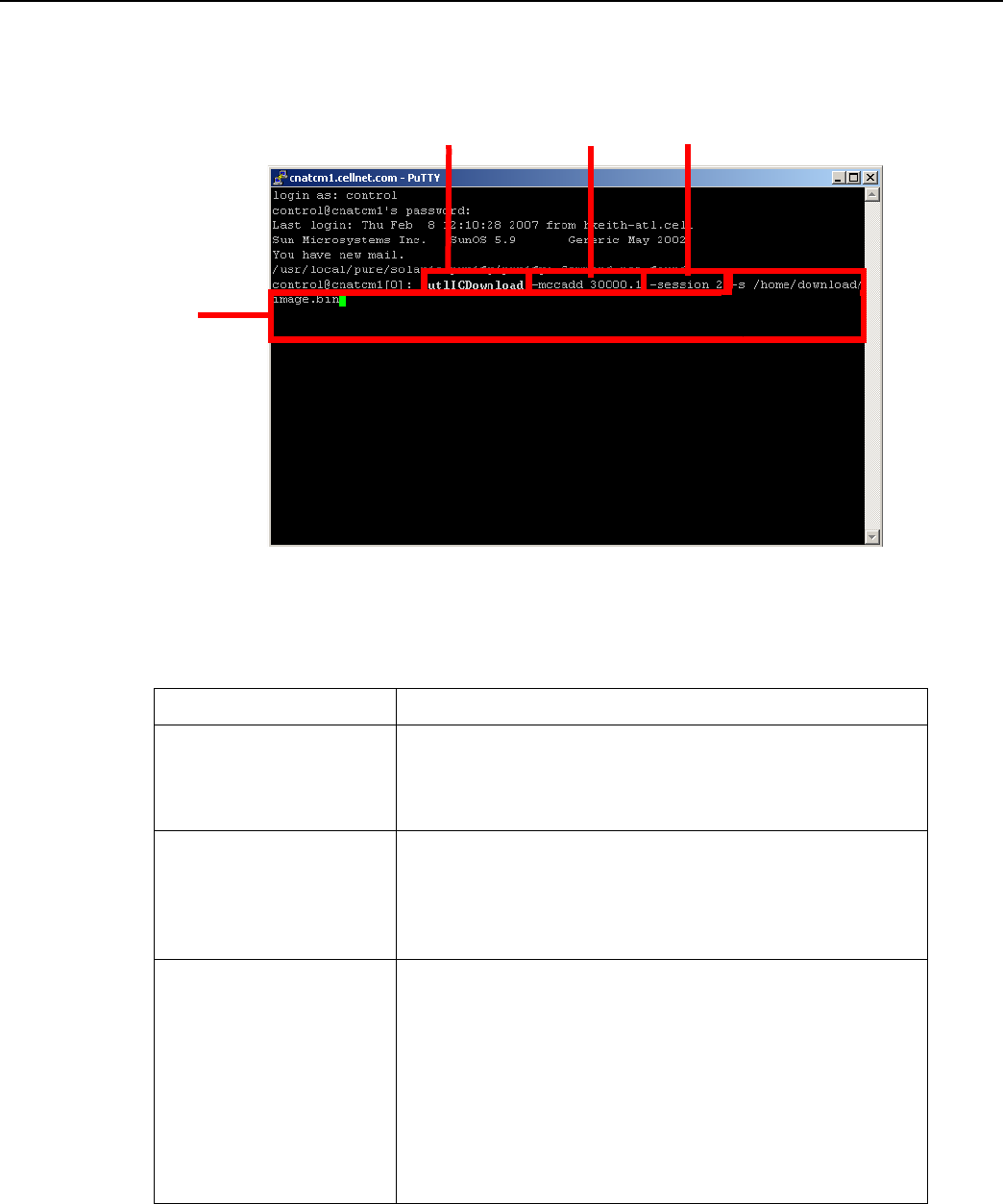
4. Launch the download program by typing utlICDownload, then indicate options.
For example, type:
utlICDownload -mccad 30000.1 -session 2 -s /home/download/
image.bin
Landis+Gyr
Chapter 6 - Performing System Upgrad
es
Network Concentrator User and Installation Guide 98-1013 Rev AF 64
Download
Application
Concentrator
ID
Session
ID
image.bin file
locations
Figure
6 - 5.
Launch OTA download
program
The following table lists all the options in the download program:
Table 6-1. Download Command Line Switches
Switch
Description
Mccad
Mccad is the concentrator address <net>.<node>
which requires a firmware upgrade.
Example: utlICDownload -mccad 30000.1
[Args Reqd: 1 defaults: 0.0 format: %lu]
Session
Session is a number between 0 - 255. This is the session ID
of the download task for the concentrator. All operations for
the download have the same session number.
Example: utlICDownload -session
5 [Args Reqd: 1 defaults: 2 format: %lu]
-s CIF file
The code image file (CIF) of the new version to be
downloaded on the concentrator is usually present in the /
home/download/MCC_Cnctr/
directory. If the directory does
not exist, create one and place the image.bin file in that
directory. Verify that it is the correct version. Downloading an
older or incorrect version can cause loss of communication
with the concentrator.
Example: utlICDownload -s /home/download/MCCCTR/
image.bin
[Args Reqd: 1 defaults: 2 format: %s]

Landis+Gyr
Chapter 6 - Performing System Upgrad
es
Network Concentrator User and Installation Guide 98-1013 Rev AF 65
Table 6-1. Download Command Line Switches (continued)
Switch
Description
-disconnect
You need the disconnect session ID if the earlier download
was terminated before completion. In this case, you must
enter all the options of the download command and include
the disconnect session ID. That should be the same
session number that was terminated earlier.
Example: utlICDownload -disconnect 5
-nohotboot
Override automatic disconnect and hotboot to avoid hot
booting the MC be fore the session. In this case, you
must start run disconnect and hotboot.
Example: utlICDownload -nohotboot -session 5 -mccad
30000.1 -s <filename>
-waittime
Time to wait (in seconds) before sending the next packet.
The download firmware process sends a total of nine
packets. The waittime option allows for a delay between
packets sent. Example: utlICDownload -waittime 4
/MCCCTR/image.bin
[Args Reqd: 1 defaults: 2 format: %s]
-bankcopy
Copy Concentrator image from B to A. The Concentrator
must be running the image from B.
This option applies to versions 14.02.06 and greater.
Example: utlICDownload -mccad 30000.1 -bankcopy
-debugprint
Dump raw hex.
Example: utlICDownload -debugprint
[Args Reqd: 1 defaults: 2 format: %s]
-help
Print help information.
Example: utlICDownload -help
-query
Get status of concentrator.
Example: utlICDownload -query
-switchover
Switchover concentrator.
Example: utlICDownload -switchover
Switchover Concentrator
After the download is complete, login to the concentrator to instruct it to switchover.
1. Open a command window on your PC.
2. Use your administrative credentials to login as control user.
3. Type
./utlICDownload -mccad 30000.1 -session 2 -switchover
The concentrator hot boots after this
st
ep.

Landis+Gyr
Chapter 6 - Performing System Upgrad
es
Network Concentrator User and Installation Guide 98-1013 Rev AF 66
Concentrator Verification
Verify that the concentrator has booted up with the latest firmware.
1. Open a command window on your PC.
2. Use your administrative credentials to login as control user.
3. Type
oms -op getattr -class mcc -mccad 30000.1 -attrnm fWRevision -
remote
Bankcopy
MCC
The Concentrator can send image data from B to memory location A. The Concentrator must be
running from location B to ensure the operation is successful.
Copy the image by typing
./utlICDownload - mccad 3000.1 -session 2 -bankcopy
Restarting a Download
You can interrupt a download to substitute a newer file than the one currently being downloaded.
1. Suspend the client program by typing
Control +
C
2. Send a disconnect command. At the prompt type
utlICDownload -mccad 30000.1 -session 2 -disconnect
3. Hot boot the concentrator.
Upgrading Concentrator Firmware Directly via Cable
You can connect a cable to the concentrator and upgrade interior components via direct cable
connection or through a wired intranet or hub. Following are direct upgrade procedures. To perform
these tasks you need:
• a concentrator
• a serial cable
• an AC power cable
• an intranet connection
• a hub (optional)
• an upgrade CD or link that includes rom.bin and image.bin files
• Hyperterminal
• a command prompt
• Network Configuration Manager
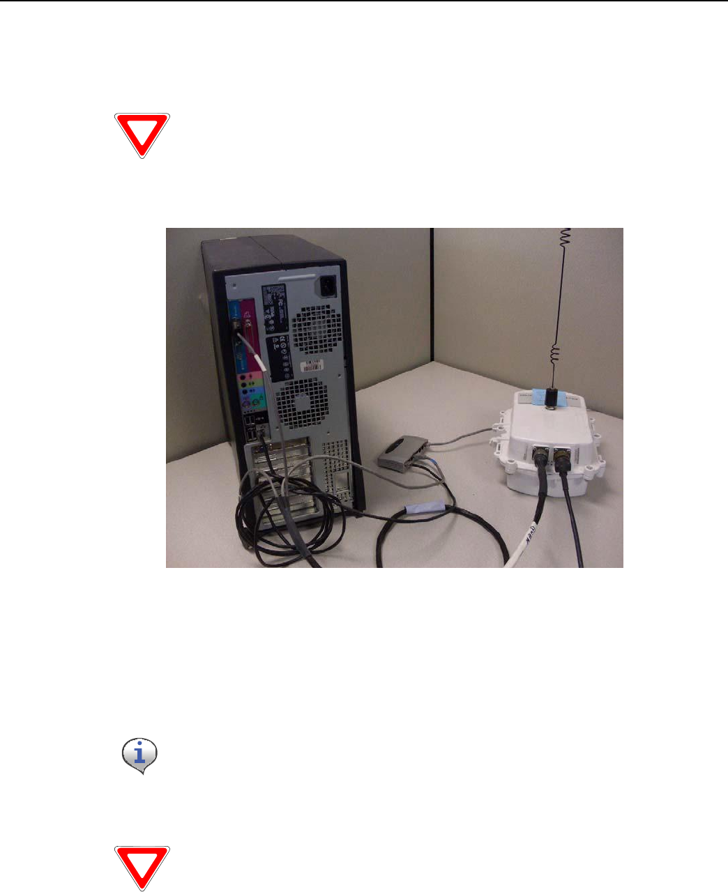
Landis+Gyr
Chapter 6 - Performing System Upgrad
es
Network Concentrator User and Installation Guide 98-1013 Rev AF 67
Connecting to the Concentrator Via Cables Using a Router
If you would like to be able to access the intranet from your PC while programming the concentrator,
then set up the cables using a router.
Use a router to perform this procedure. This procedure is not designed to
wo
rk
with a
switch.
It enables you to share one intranet connection with your PC and your concentrator simultaneously.
Figure
6 - 6.
Diagram
of
router cable setup
1. Connect the programming cable branch (labeled “Console”) to the concentrator.
2. Connect the ethernet branch (labeled “Ethernet”) to the router.
3. Plug your network cable into the router.
4. Connect the router to the network port on the PC via network cable.
5. Connect the other end of the programming cable to the COM port on the PC.
Do not plug the LPP branch into the PC.
6. Launch Hyperterminal on the PC.
Launch Hyperterminal before supplying power to the
conc
en
tr
ator
.
7. “Boot Up in Dialog”, type y for yes.
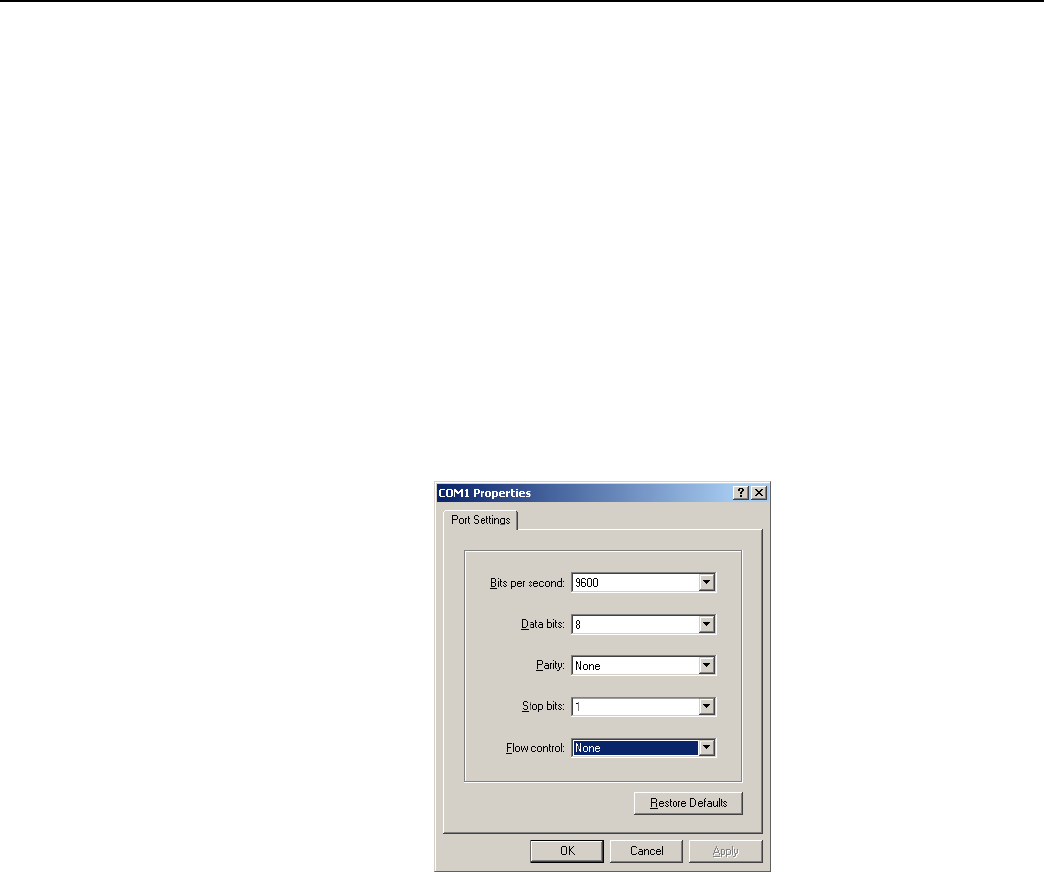
Landis+Gyr
Chapter 6 - Performing System Upgrad
es
Network Concentrator User and Installation Guide 98-1013 Rev AF 68
8. Connect the AC power cable to the concentrator, and plug the other end into an outlet.
Loading the Concentrator Firmware Via Cables Using a Router
Hyperterminal automatically detects the concentrator. If it does not, close the Hyperterminal session,
unplug the concentrator, and start again.
1. Assign the concentrator an IP address.
• In Hyperterminal, specify the COM 1 port and properties as follows:
• Bits per second: 9600 baud
• Data bits: 8
• Parity: None
• Stop bits: 1
• Flow control: None.
Figure
6 - 7.
Hyperterminal COM port and
properties
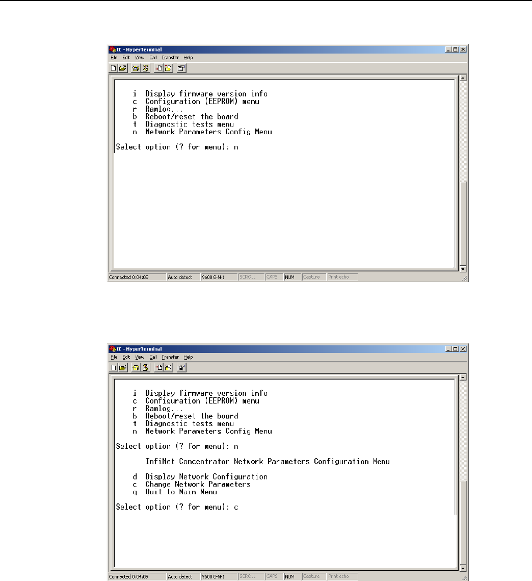
Landis+Gyr
Chapter 6 - Performing System Upgrad
es
Network Concentrator User and Installation Guide 98-1013 Rev AF 69
A. When the Diagnostic Mode menu displays, type n to configure network parameters.
Figure
6 - 8.
Hyperterminal configure network
parameters
B. Type c for Change Network Parameters.
Figure
6 - 9.
Hyperterminal change network
parameters
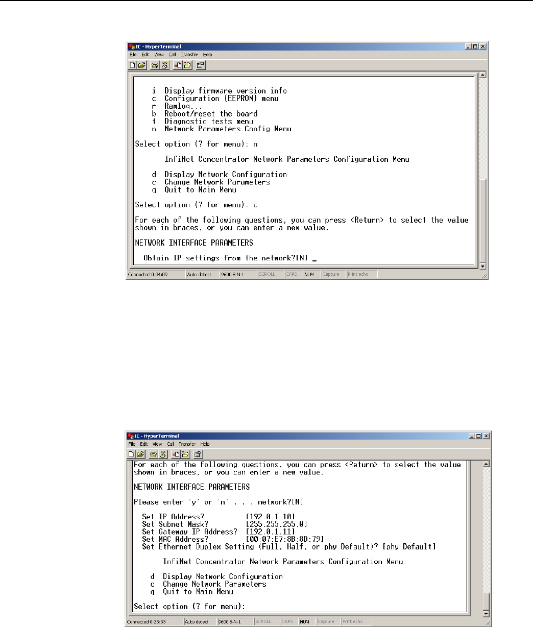
Landis+Gyr
Chapter 6 - Performing System Upgrad
es
Network Concentrator User and Installation Guide 98-1013 Rev AF 70
C. Type y for Yes to go to the network to dynamically obtain an IP address.
Figure
6 - 10.
Hyperterminal obtain
IP
from network
D. Press the Enter key to keep the default options:
• Set IP Address?
• Set Subnet.Mask?
• Set Gateway IP Address?
• Set NAC Address?
• Set Ethernet Duplex Setting?
Figure
6 - 11.
Hyperterminal keep default settings
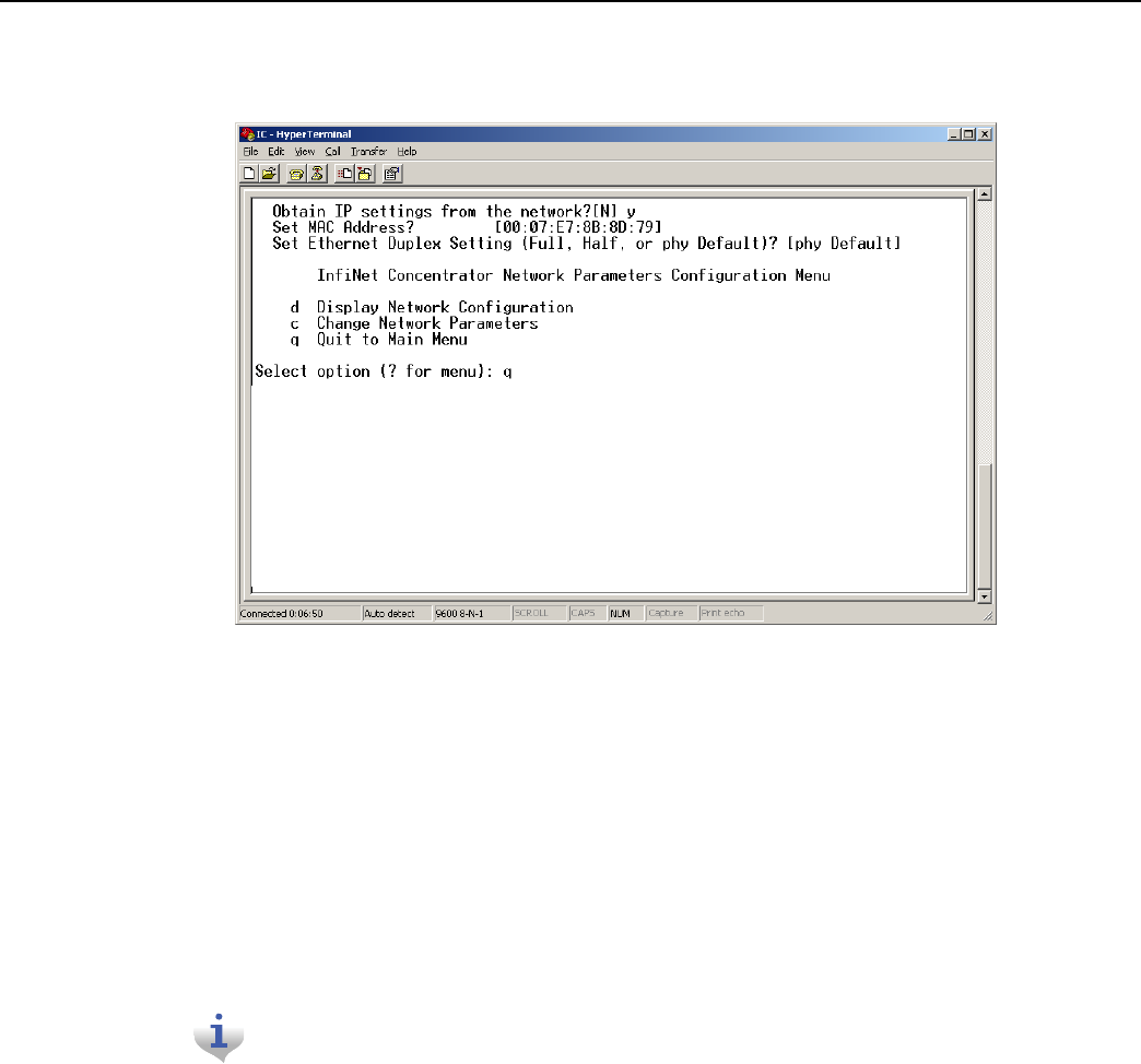
Landis+Gyr
Chapter 6 - Performing System Upgrad
es
Network Concentrator User and Installation Guide 98-1013 Rev AF 71
E. Type q for Quit. Hyperterminal displays a message to let you know it is saving changes in
memory.
Figure
6 - 12.
Hyperterminal quit Diagnostics
F. Type b to Boot the concentrator.
G. Type y for Yes to reset the system. Wait for the reset to complete. When Hyperterminal
restarts, it displays new IP address. Note the IP address; you will need it for subsequent
steps.
2. Copy the rom.bin and image.bin files to your c:\ drive before starting the update Flash memory
process.
3. Update the rom.bin file.
A. Open a command prompt window, usually under Start | Programs | Accessories. Keep
Hyperterminal open.
Try to position the c:\ prompt and Hyperterminal windows so that you can see
both of them at o
n
c
e
.
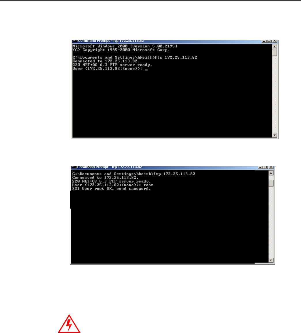
Landis+Gyr
Chapter 6 - Performing System Upgrad
es
Network Concentrator User and Installation Guide 98-1013 Rev AF 72
B. Type ftp, space, and then the IP address just assigned to your concentrator, in this example
ftp 172.25.113.82. The command window connects to the CPU to update the
rom.bin.
Figure
6 - 13. C:\
prompt
C. Type the user
root
then the Enter key. The user is case-sensitive.
Figure
6 - 14. C:\
root
D. Type password Netsilicon or password, then the Enter key.This password is case-
sensitive.
E. Type bin, then the Enter key.
Skipping this critical step corrupts the image on your concentra
t
or.
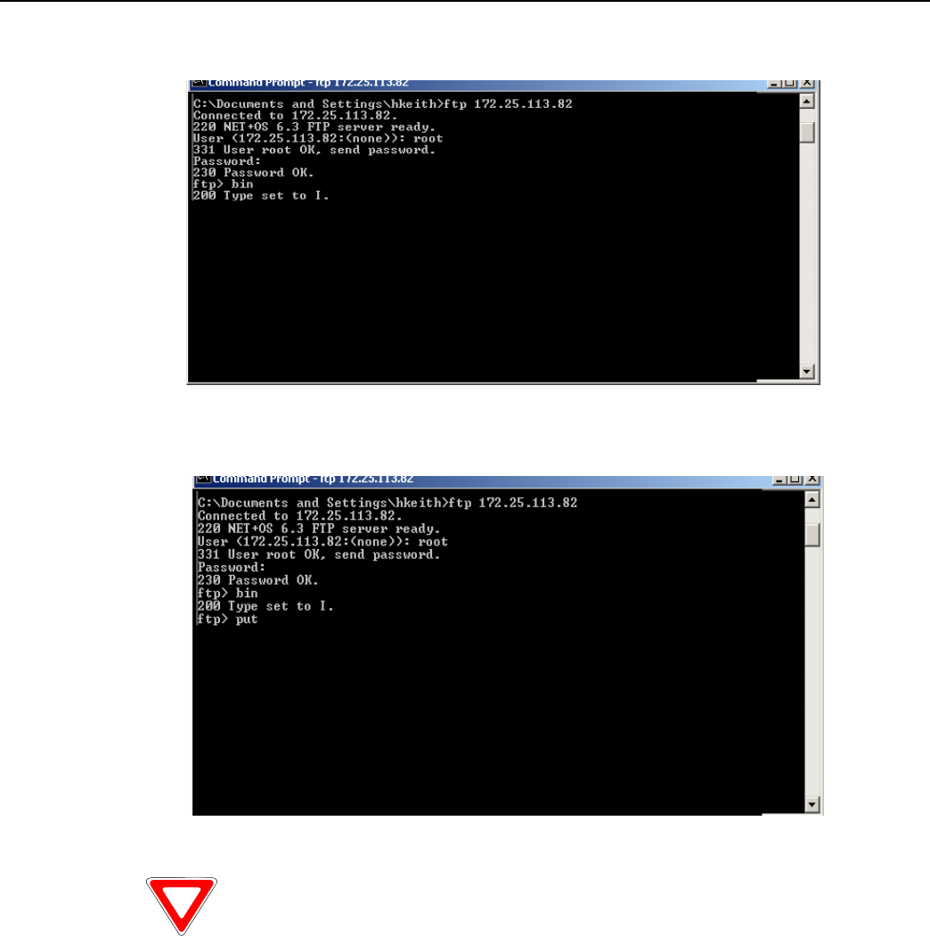
Landis+Gyr
Chapter 6 - Performing System Upgrad
es
Network Concentrator User and Installation Guide 98-1013 Rev AF 73
Figure
6 - 15. c:\ password
F. Type put c:\rom.bin, then the Enter key
C:\rom.bin
Figure
6 - 16.
.put
C:\rom.bin
If the bin files are located somewhere other than the C:\ drive, type the
c
o
rr
e
c
t
file path in this step.
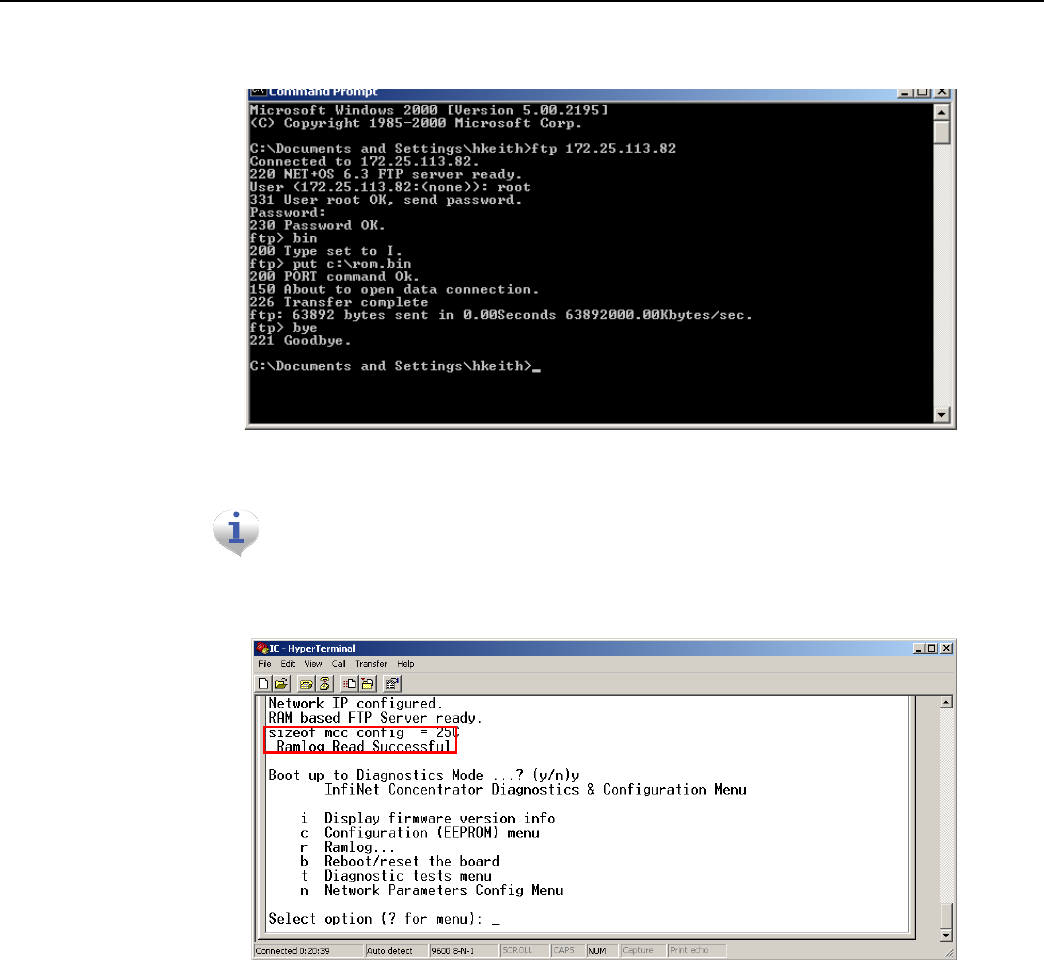
Landis+Gyr
Chapter 6 - Performing System Upgrad
es
Network Concentrator User and Installation Guide 98-1013 Rev AF 74
G. Type bye.
Figure
6 - 17. C:\bye
After a few seconds, Hyperterminal displays messages to confirm a
su
cce
ss
ful
restart. When you see the message “Ramlog Read Successful,” you
c
a
n
continue with the programming
pr
oces
s.
Figure
6 - 18.
Ramlog read successful
message
4. Boot to Diagnostics Mode by typing y for yes in the Hyperterminal window.
5. Update the image.bin file.
A. Open a command prompt window, usually under Start | Programs | Accessories.
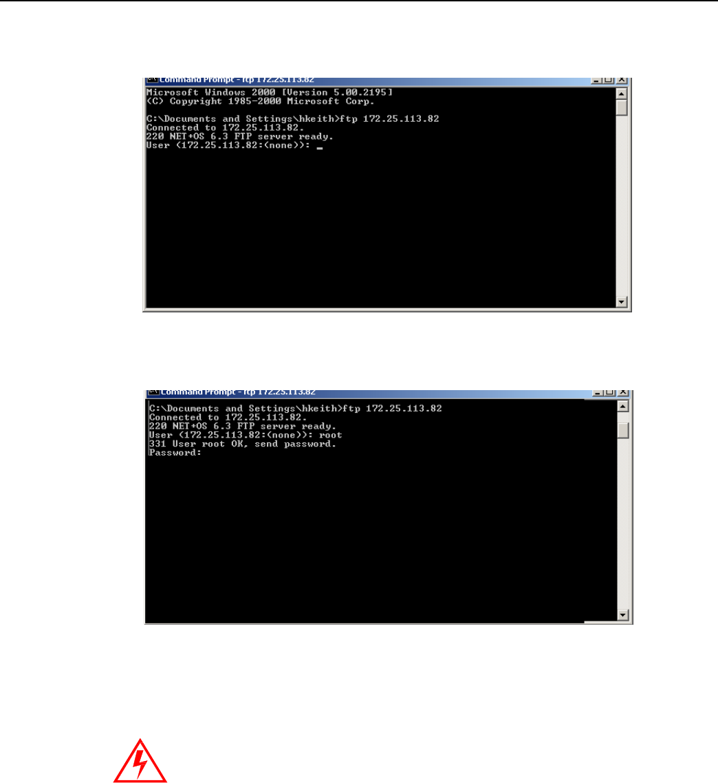
Landis+Gyr
Chapter 6 - Performing System Upgrad
es
Network Concentrator User and Installation Guide 98-1013 Rev AF 75
B. Type ftp, space, and then the IP address just assigned to your concentrator, for example ftp
192.0.1.10. The command window connects to the CPU board to update the image.bin.
Figure
6 - 19. C:\
prompt
C. Type user root, then the Enter key.The user is case-sensitive.
Figure
6 - 20.
C:\root
D. Type password Netsilicon or password, then the Enter key. This password is case-
sensitive.
E. Type bin, then the Enter key.
Skipping this critical step corrupts the image on your concentra
t
or.
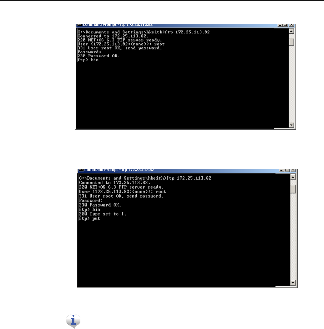
Landis+Gyr
Chapter 6 - Performing System Upgrad
es
Network Concentrator User and Installation Guide 98-1013 Rev AF 76
.
Figure
6 - 21.
C:\Netsilicon
F. Type put c:\image.bin, then the Enter key.
Figure
6 - 22. put
C:\image.bin.
If you saved the bin files somewhere other than the C:\ drive, then type
th
e
correct file path in this
st
ep.
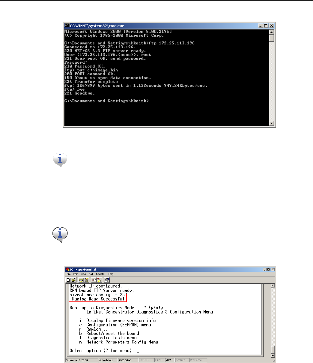
Landis+Gyr
Chapter 6 - Performing System Upgrad
es
Network Concentrator User and Installation Guide 98-1013 Rev AF 77
G. Type bye.
Figure
6 - 23. C:\bye
After a few seconds, Hyperterminal displays messages to confirm a
su
cce
ss
ful
restart. When you see the message “Ramlog Read Successful,” you
c
a
n
continue with the programming
pr
oces
s.
6. Boot to Diagnostics Mode by typing y for yes in the Hyperterminal window.
7. When the command prompt displays a message to say the transfer is complete, type
bye
to reset
the board.
8. Return to Hyperterminal. Type y for Yes to return to the Diagnostics menu.
Return to Diagnostics quickly, or Hyperterminal tries to obtain another new IP
addr
ess.
9. Confirm the subnet mask address.
Figure
6 - 24.
Ramlog read successful
message
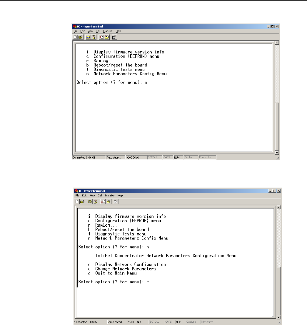
Landis+Gyr
Chapter 6 - Performing System Upgrad
es
Network Concentrator User and Installation Guide 98-1013 Rev AF 78
H. In the Diagnostics Menu, type n for Network Parameters Config Menu.
Figure
6 - 25.
Hyperterminal network configuration
I. Type c for Change Network Parameters.
Figure
6 - 26.
Hyperterminal change
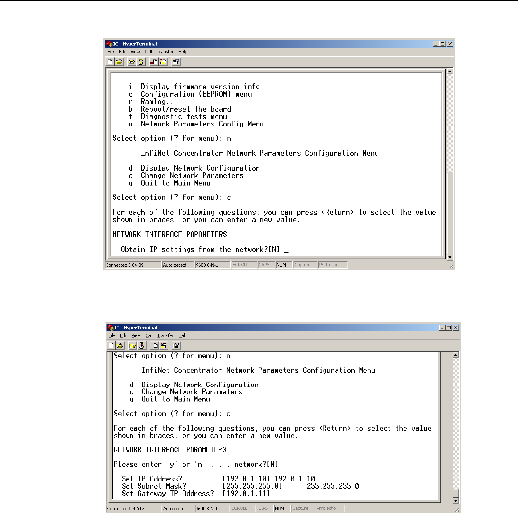
Landis+Gyr
Chapter 6 - Performing System Upgrad
es
Network Concentrator User and Installation Guide 98-1013 Rev AF 79
J. Press the Enter key at N to specify a static IP.
Figure
6 - 27.
Hyperterminal no
K. At the Subnet mask prompt, re-type the subnet indicated by Hyperterminal.
Figure
6 - 28.
Hyperterminal re-type subnet mask
L. Press the Enter key for the rest of the default options:
• Set IP Address?
• Set Subnet.Mask?
• Set Gateway IP Address?
• Set NAC Address?
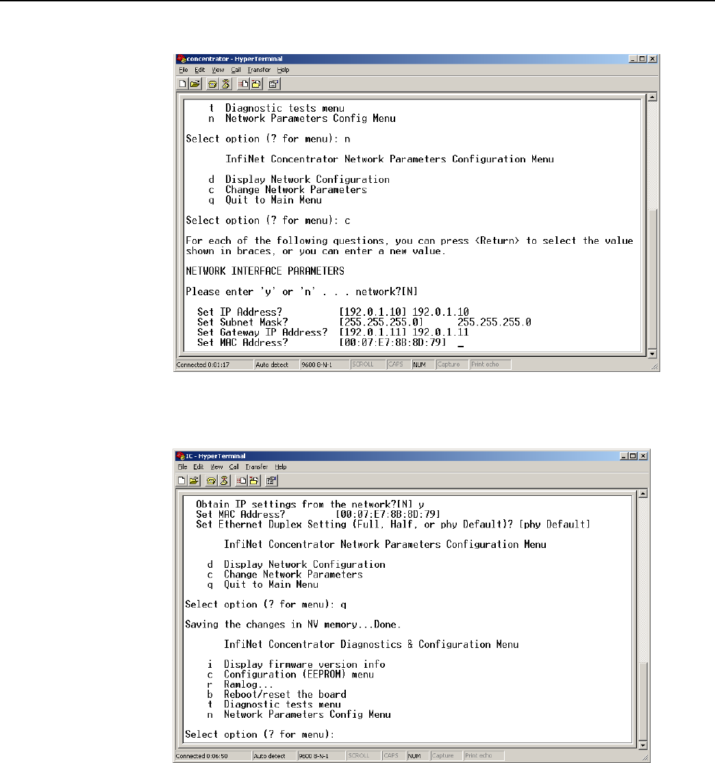
Landis+Gyr
Chapter 6 - Performing System Upgrad
es
Network Concentrator User and Installation Guide 98-1013 Rev AF 80
M. Set Ethernet Duplex Setting?
Figure
6 - 29.
Hyperterminal accept default network options
N. Type q for Quit.
Figure
6 - 30.
Hyperterminal quit
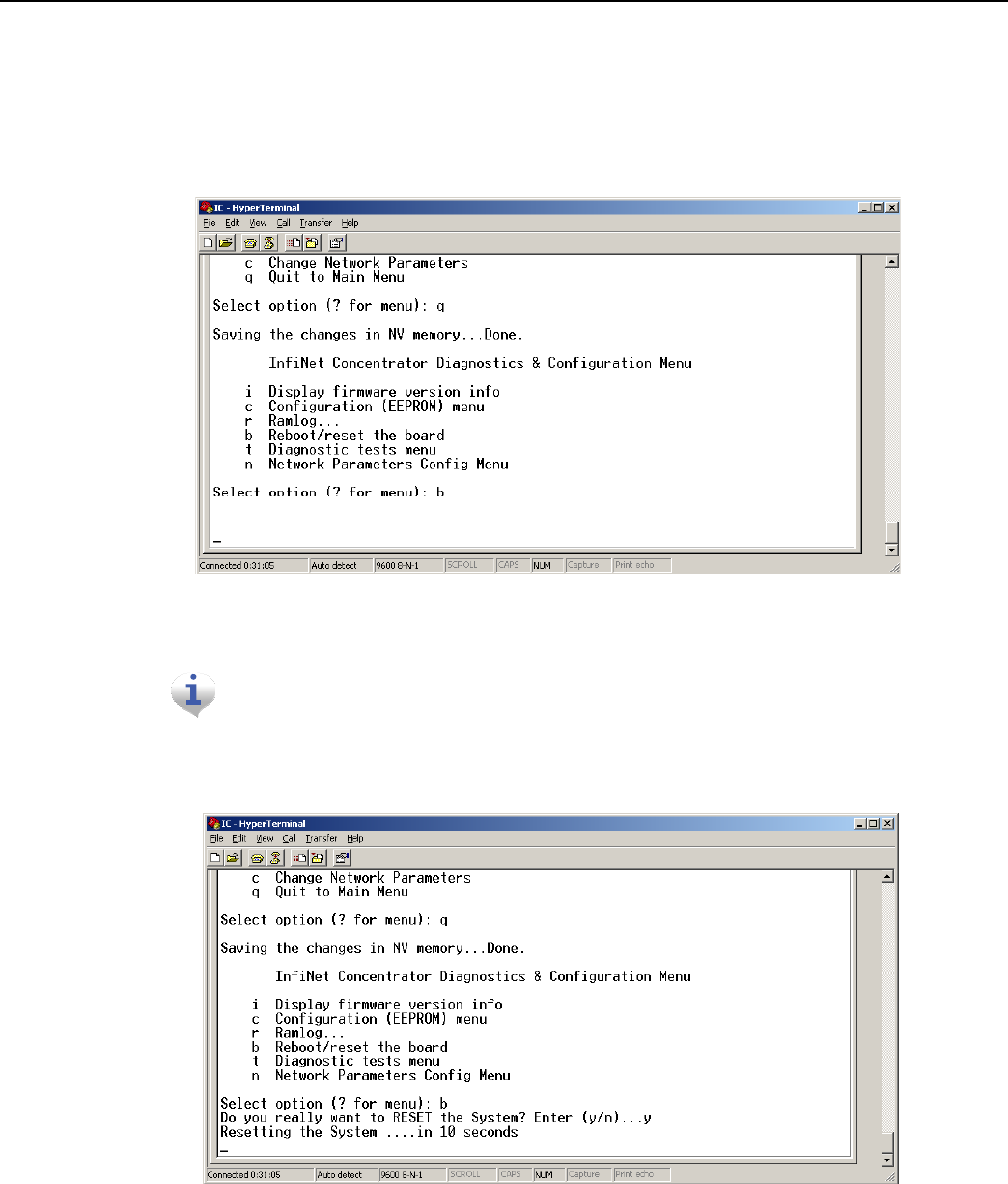
Landis+Gyr
Chapter 6 - Performing System Upgrad
es
Network Concentrator User and Installation Guide 98-1013 Rev AF 81
Testing the Concentrator
Test the concentrator to verify that it has been programmed correctly.
1. Unplug the ethernet cable from the router.
2. In the Diagnostics menu, type b to reboot the concentrator system.
Figure
6 - 31.
Diagnostic Menu
3. Hyperterminal reboot
If the Diagnostics Menu does not display, then start over again from the fir
s
t
step in this
se
ctio
n.
4. Type y to Yes, reset the system.Wait for the system to boot into normal operation.
Figure
6 - 32.
Hyperterminal rebooting
message
5. Type i to display firmware version information.
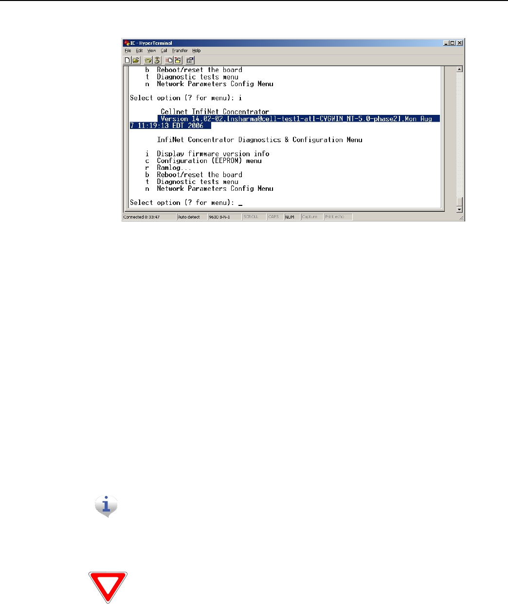
Landis+Gyr
Chapter 6 - Performing System Upgrad
es
Network Concentrator User and Installation Guide 98-1013 Rev AF 82
6. Verify the version number.
7. Unhook all the cables.
Figure
6 - 33.
Hyperterminal
reboot
Upgrading IWR Radio Firmwar
e
To perform these tasks you need:
• Direct or OTA concentrator connection
• RadioShop
Specific instructions for updating the IWR firmware using RadioShop are in the RadioShop Getting
Started Guide.
Upgrading the Radio’s DCW
A Device Control Word (DCW) is a program written in the UtiliNet programming language. DCWs
execute within UtiliNet devices and provide the ability to control the device. The DCW interacts
with firmware and directs the radio to do things such as reboot or perform advanced functions.
For instance, the MCCTIME.hex DCW contains the current version of MCC
Helper. MCC Helper queries the radio to get its ID, and begins
sen
d
ing
discovery packets to the assigned Take Out
Poin
t.
If you are upgrading to DCW version 1.16F, see “Field Upgrade to DCW
1.16
F
”
on page 117.

Landis+Gyr
Chapter 6 - Performing System Upgrad
es
Network Concentrator User and Installation Guide 98-1013 Rev AF 83
Upgrade the concentrator’s DCW with Network Configuration Manager tool, via direct or OTA
connection.
1. Open the Network Configuration Manager tool.
2. Connect to the concentrator’s radio.
3. Click the Load DCW button.
4. Select the DCW from the file list.
5. Click the Open button.
6. The DCW loads and a series of messages display along the status bar of the Network
Configuration Manager
window.
7. Network Configuration Manager displays a message when the DCW loads successfully.
The MCC Helper DCW displays in the DCW section of the window. Verify
wit
h
customer support at ëçäì
íá
çå
ëì
éé
çê
íK
å~
]ä~å
Ç
á
ëÖ
óê
K
Å
ç
ã
that you have the
most
current version.
For more information about working with DCWs, see the Network Configuration Manager Users
Guide.
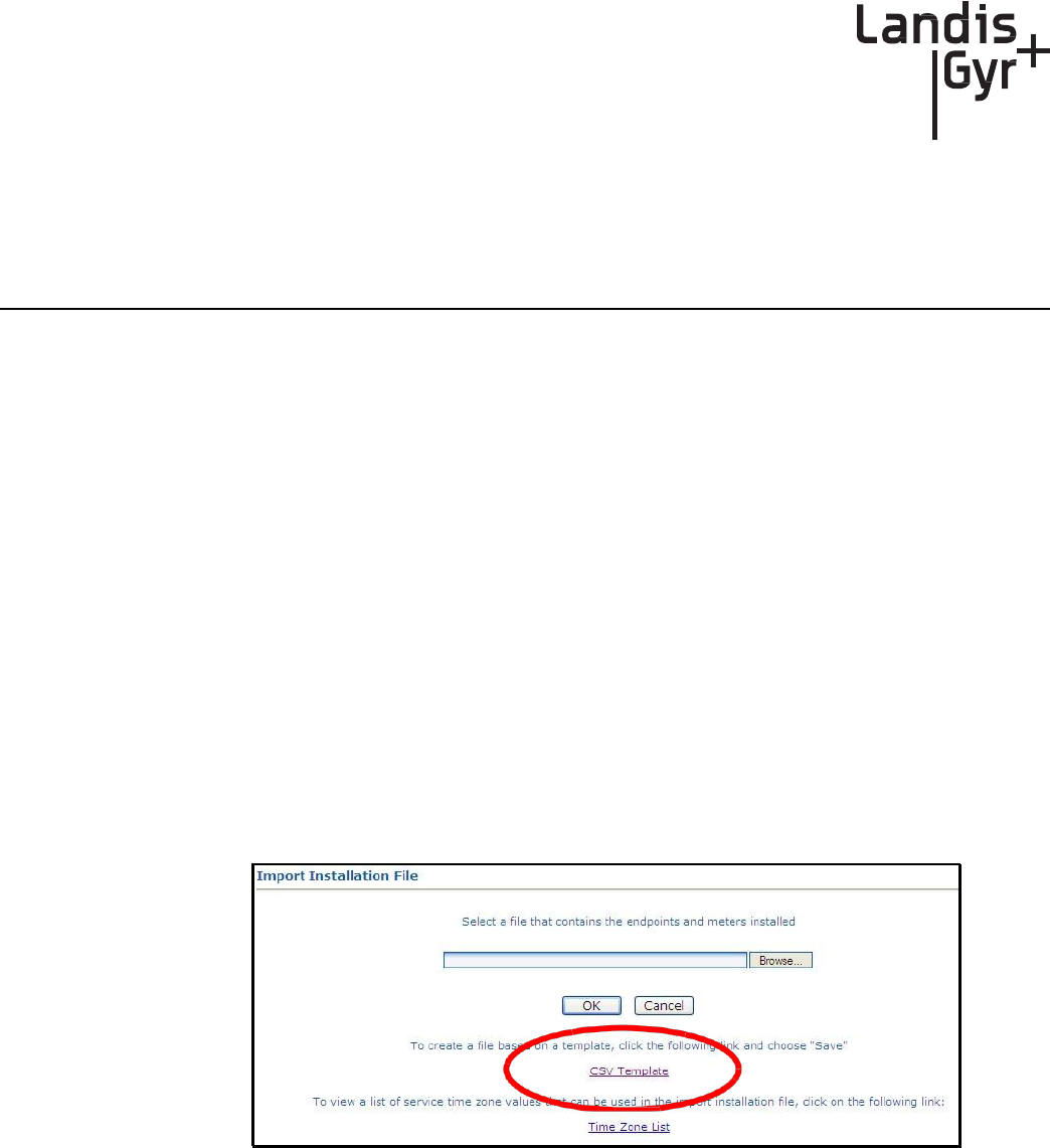
Network Concentrator User and Installation Guide 98-1013 Rev AF 84
7
Routers in Command
Center
Importing Routers into Command Center
The following section describes the process of manually importing Routers into Command Center.
The minimum data set required to successfully import the Router into Command Center includes:
Wan ID, User ID, Installation Date, Installation Time, Installed Meter No, Installed Endpoint SN,
and Service Time Zone.
Generating the Import Installation File (IIF)
The IIF is always required, even if using Router Auto Registration. When a Router has been
physically installed in the field, certain data must be reported back to the Command Center staff in
order to generate the IIF.
Create a CSV File for the IIF Information
Command Center can generate a template IIF (in CSV format).
1. From Command Center home, select Operations > Import > Import Installation File.
The Import Installation File window will
open.
Figure
7 - 1.
Import Installation Window
2. Click the CSV Template link.
3. Select Save and designate the file location.
4. Open up the saved.CSV file with Microsoft Excel.
5. Fill in the columns with the appropriate data. Each row in the document represents one router (or
Endpoint) and should only contain data related to that specific unit.
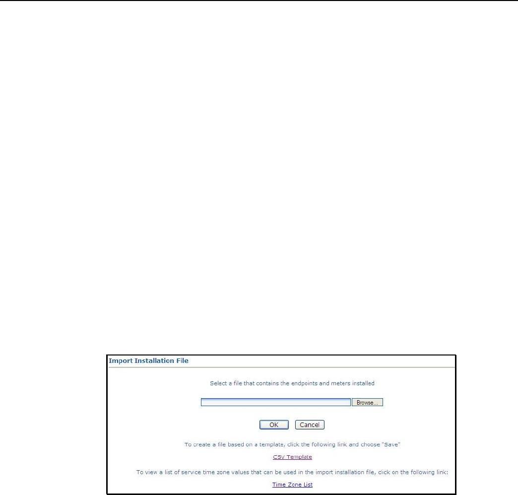
Landis+Gyr
Chapter 7 - Routers in Command Center
Network Concentrator User and Installation Guide 98-1013 Rev AF 85
CSV File Fields
• UserID: 1 (Router default)
• InstallationDate: Local Date (preferably collected by installer when operation performed).
• InstallationTime: Local Time (preferably collected by installer when operation performed).
• ChangeOutMeterNo: N/A
•
ChangeOutMeterkWh
:
N/A
• InstalledMeterNo: ID assigned by the Network Engineers.
• InstalledEndpointSN: Serial number of the Router in decimal. (equivalent to LanID converted
to decimal)
• InstalledMeterkWh: N/A
• ServiceLatitude: LAT
• ServiceLongitude: LONG
• ServiceLocation: Same as InstalledMeterNo
• ServiceTimeZone: See “Time Zone” on page 87.
Importing the IIF
After the IIF has been created and saved, it must be imported into Command Center.
1. From Command Center home, select Operations > Import > Import Installation File.
The Import Installation File window will
open.
Figure
7 - 2.
Import Installation File
Window
2. Enter the path to the location of the Import Installation File created earlier.
...or...
3. Click the Browse button to navigate to the location of the desired file.
4. Click Save to upload the file.
5. The router described in the IIF should now appear in Command Center. The router should
display the data entered for it and have the status 'Installed'.
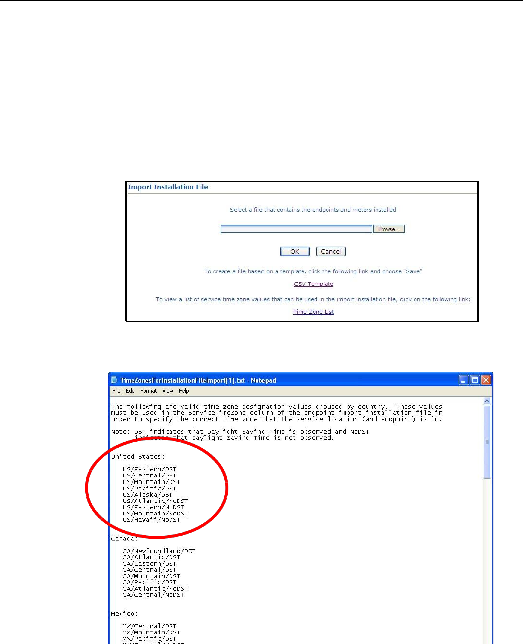
Landis+Gyr
Chapter 7 - Routers in Command Center
Network Concentrator User and Installation Guide 98-1013 Rev AF 86
Time Zone
In order to report readings time correctly, the router must be programmed with the appropriate time
zone. This is achieved by sending commands to the router that indicates the time zone in which the
endpoint is installed and whether Daylight Savings Time (DST) is observed in the given time zone.
The meter installer should include the endpoint time zone in the Installation File. To make it easy for
installers to specify a time zone, the Time Zone List link will open a document that displays a list of
valid time zone designations by country.
1. From Command Center home, select Operations > Import > Import Installation File.
The Import Installation File window will open.
Figure
7 - 3.
Import Installation File Window
2. Click on the Time Zone List Link. The
TimeZonesForInstallation
window will open.
Figure
7 - 4.
Time Zone List
3. Note the correct Time Zone Value for your IIF.
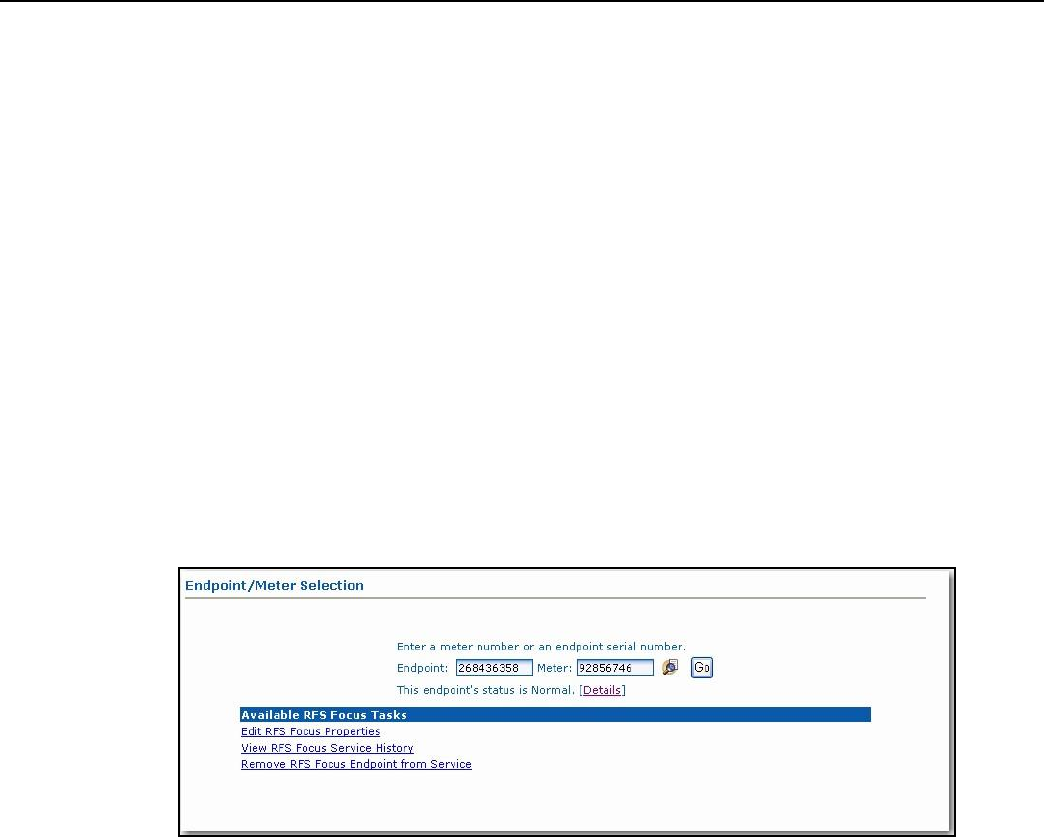
Landis+Gyr
Chapter 7 - Routers in Command Center
Network Concentrator User and Installation Guide 98-1013 Rev AF 87
RF Network Settings
The RF Network Settings establish organization level settings for outage wait values, time
synchronization, etc. The RF Network Settings are a part of the endpoint configuration and may only
be changed by Landis+Gyr technical support.
Command Center Operation
Router
This function allows the user to remove a deployed router from service. The removed router can
either be put back into inventory or archived.
1. From Command Center, select Operations > Endpoints. The Endpoint/Meter Selection
window will open.
2. Enter the Meter Number of the existing meter.
3. Click GO. The Available Tasks list will appear. This list will vary based on model of the meter.
Figure
7 - 5.
Endpoint/Meter Selection Available RFS Focus Tasks
4. From the Available Tasks, select the Remove Endpoint from Service link. The Remove
Endpoint From Service window will open, shown in Figure 7 - 6.
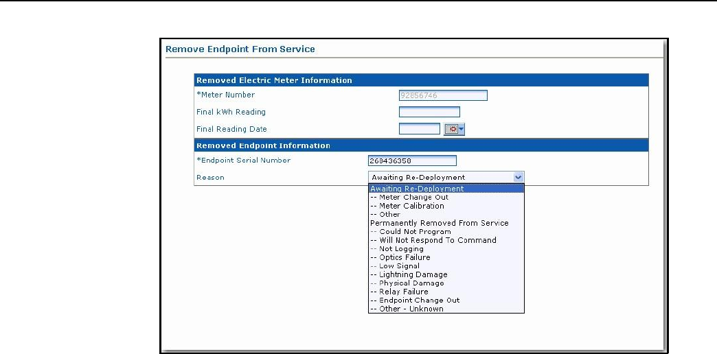
Landis+Gyr
Chapter 7 - Routers in Command Center
Network Concentrator User and Installation Guide 98-1013 Rev AF 88
Figure
7 - 6.
Remove Endpoint From Service
5. Enter Removed Electric Meter
Information:
A.
Enter the Final kWh Reading (Optional)
B. Enter the Final Reading Date (Optional)
C. Enter Removed Endpoint Information. Select a reason for the removal from the drop
down list box.
D. Awaiting Redeployment. This option will transition the endpoint to Inventory
status.
E. Permanently Remove From Service. This option will archive the endpoint. An endpoint in
archived status will not be included in any Command Center reports.
6. Click Save to save changes. A message indicating the success or failure of the removal will be
displayed.
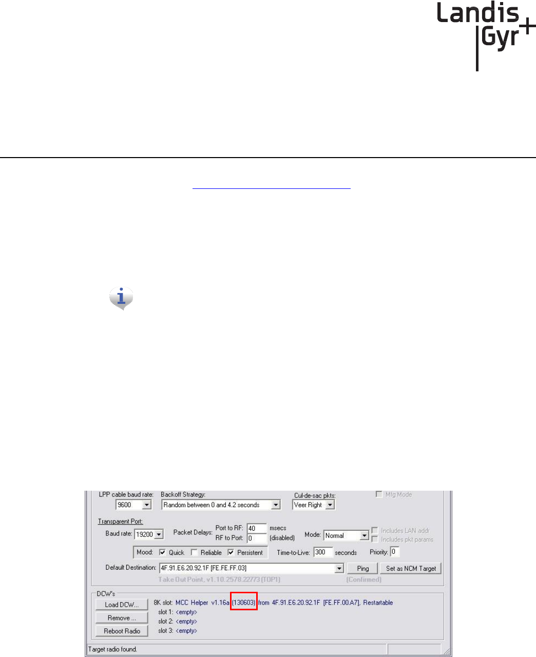
Network Concentrator User and Installation Guide 98-1013 Rev AF 91
8
Troubleshooting
This chapter lists common issues and steps to take to solve related problems. Contact Landis+Gyr
Customer Operations at ëçäìíáçåëìééçêíK
å~
]ä~å
ÇáëÖóê
KÅ
çã
with questions.
Verifying
Configuration
If the network does not discover a concentrator, verify that the correct Network ID and destination
are programmed into the radio. If so, then verify that the radio can communicate with the TOP.
The Network Configuration Manager application is required to perform these
steps.
To verify communications with the TOP, use the ping command in the Network Configuration
Manager application. This sends a message to the TOP and back to verify the TOP exists. Ping while
plugged directly into the concentrator via a cable or over the air via another radio from the ground
that is connected to the concentrator.
• If the ping is not successful, double-check the destination or choose another TOP.
• If the ping is successful, ensure that the radio is able to read the MCCID in the CPU.
To check the CPU, connect to the radio, and then locate the MCCID (in format MCC Helper v1.16a
(130603) from the DCW list on the Network Configuration Manager main screen, as shown in
Figure 8 - 1.
Figure
8 - 1.
MCCID
If the MCCID is zero (in format MCC Helper v1.16a (0) from 4F.91.E6.20.92.1F
[FE.FF.00.A7]), a CPU configuration failure occurred and the DCW was unable to

Chapter 8 -
T
r
o
u
ble
sh
oo
t
in
g
Landis+Gyr
Network Concentrator User and Installation Guide 98-1013 Rev AF 92
communicate with the CPU. To configure the CPU so it can communicate with the DCW, complete
the following steps:
1. Connect to the CPU using Hyperterm, and then select Y in the Boot screen to boot the unit into
diagnostic mode.
2. Type C.
The EEPROM Configuration menu is displayed for you to verify information.
3. Verify or edit the programmed values for:
• MccNetAddress
• MccNodeAddress
• LogMgrNetAdddress
• LogMgrNodeAddress
• AlarmNetAddress
• AlarmNodeAddress
• MinutesFromGMT
• DayLightSavingsType
Follow the instructions and exit the EPROM menu, booting only if requested by the unit.

Network Concentrator User and Installation Guide 98-1013 Rev AF 93
A
Performance
Product Specifications
Table A-1. Product Specifications
Element
Description
Concentrator Dimensions
(excludes antennas)
H x W x D
4.9"x11.82"x9.30"
Antennas
Three (3), one on top and two on the bottom.
Typical antenna length is 17.5".
Weight
12.5 Lbs.
Operating Frequency Band
902-928 MHz
Transmit Output Power
21, 25, 30 dBm (user selectable)
Standards Compliance
FCC Part 15, Class B
Operating AC Voltage
Autoranging 120-277
Operating Temperature
-40°C to 85°C
Storage Temperature
-40°C to 85°C
Color
White
Enclosure Material/Type
Aluminum/NEMA-4
Battery Backup Time
8 hrs, typical
Data Storage
3 days, typical
Backup Battery
Sealed lead-acid 12V 4.5 Amp/hr battery
Mounting Options
Utility pole and streetlights
Communication Technology
Direct Sequence Spread Spectrum - LAN, Asynchronous
Frequency Hopping Spread Spectrum - WAN
Modulation Scheme
On/Off Keying (OOK) - LAN
Frequency Shift Keying (FSK) -
WAN
Number of Network Elements Under
Control
• 1500 max. Communication modules, max
• 500-1,000 modules, typical
Regulatory Devices Supported
Electric (kWh, Kvar), Gas, Water

Appendix A - Performance
Landis+Gyr
Network Concentrator User and Installation Guide 98-1013 Rev AF 94
Table A-1. Product Specifications(Continued)
Element
Description
Types of Data Available
Consumption, TOU, Peak Demand, Interval Load
Profile, Power Quality
Critical Alarms
Power Outage, Communication Loss
Power Statistics
Table A-2. Power Statistics
Voltage In
(Vac)
Current In
(Amps)
Load
Power In (W)
120
0.151
Battery charged/transmitting
12.75
240
0.086
Battery charged/transmitting
12.15
120
0.085
Battery charged/receive only
6.35
240
0.050
Battery charged/receive only
6.35
120
0.200
Battery charging/transmitting
17.13
240
0.120
Battery charging/transmitting
16.00
WAN Statistics
Table A-3. WAN Stats: General
Element
Description
Frequency Range
License-free, 902-928 MHz
Channels
240
Channel Spacing
100 kHz
Raw RF Data Rate
9600/19,200 bps
Spreading Technique
Frequency Hopping
Hopping Technique
Pseudo Random, Asynchronous
Hopping Patterns
65,536 (Unique per Network)
Network Address
Latitude/Longitude Coordinates
Frequency Stability
2.5 ppm

Network Concentrator User and Installation Guide 98-1013 Rev AF 95
Landis+Gyr Appendix A - Performance
Table A-4. WAN
Stats: EMI & Power/Control Susceptibility
Element
Description
Electromagnetic Radiation
FCC Class B, Part 15.247
Electromagnetic
Susceptibility
ANSI C37.90.2 Modified
Surge Withstanding
Capability
ANSI C37.90.1 and ANSI C62.41
Electrostatic Discharge
IEC 801.2
Table A-5. WAN Stats: Agency Appro
v
als
Element
Description
FCC Certified
Part 15.247

Network Concentrator User and Installation Guide 98-1013 Rev AF 97
B
Compliance
FCC Class B
This equipment has been tested and found to comply with the limits for a Class B digital device,
pursuant to Part 15 of the FCC Rules. These limits are designed to provide reasonable protection
against harmful interference in a residential installation. This equipment generates, uses, and can
radiate radio frequency energy and, if not installed and used in accordance with the Instructions, may
cause harmful interference to radio communications. However, there is no guarantee
that interference
will not occur in a particular installation. If this equipment does cause harmful interference to radio
or television reception, which can be determined by turning the equipment off and on, the user is
encouraged to try to correct the interference by one or more of the following measures:
• Reorient or relocate the receiving antenna.
• Increase the separation between the equipment and receiver.
• Connect the equipment to an outlet on a circuit different from that to which the receiver is
connected.
• Consult the dealer or an experienced radio/TV technician for help.
Changes or modifications not
expressly
approved by
Landis+Gyr
for
compliance could void the user’s authority to operate the equipment.
RF Exposure
This equipment complies with FCC radiation exposure limits set forth for an uncontrolled
environment. This equipment should be installed and operated with a minimum distance of 22 cm
between the radiator and your body. This transmitter must not be co-located or operated in
conjunction with any other antenna or transmitter.
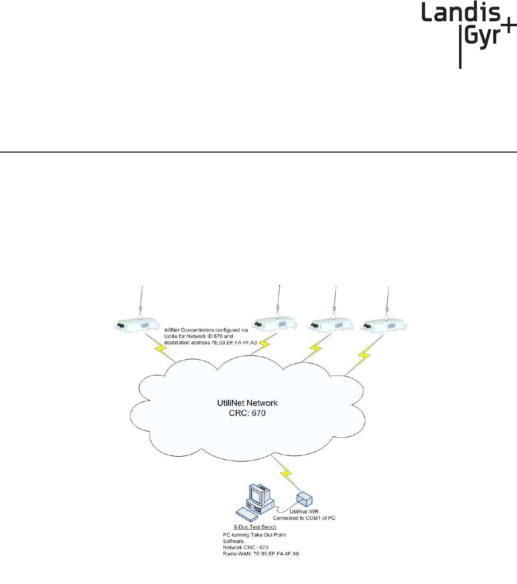
Network Concentrator User and Installation Guide 98-1013 Rev AF 99
C
Bench Testing
The Concentrator Test Bench verifies the following critical functionality before deployment to the
field.
• WAN connectivity (DCW and UtiliNet radio configuration).
• CPU configuration.
• LAN transceiver status.
Figure
C.1
Cross Dock Test
Setup
The test setup consists of about 10 to 15 concentrators configured to work with the UtiliNet test
network (Network ID 670).
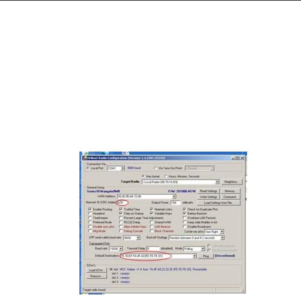
Landis+Gyr
Appendix C - Bench Testing
Network Concentrator User and Installation Guide 98-1013 Rev AF 100
Testing Concentrators
The steps involved in the test process are explained below.
1. Configuration.
Configure the concentrators in the test bench 24 hours before starting the test.
2. Verification.
Perform the actual test verification procedure at least 24 hours (up to 48 hours) prior to the
deployment.
3. Reconfiguration.
Before the final deployment, reconfigure concentrators for the utility Network ID. Modify the
default destination address to one of the utility TOPs.
Configuration
Both the Console/LAN Packet Protocol cable (PN 19-1126) and the Network Configuration
Manager application are required to configure the WAN radio in the concentrator. The test Network
ID and the Default Destination address of the test TOP are highlighted in Figure C.2.
Figure
C.2
Sample Network Configuration Manager Settings
for Concentrators
Verification
To verify the operational condition of the concentrator:
1. Connect the Console port DB9 connector of the Console/LAN Packet Protocol cable (PN 19-
1126) to the COM port of a laptop or a PC.
2. Configure the port for the following:
• 9600 baud
• 8 bits
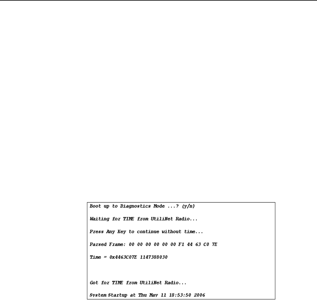
Landis+Gyr
Appendix C - Bench Testing
Network Concentrator User and Installation Guide 98-1013 Rev AF 101
• No parity
• 1 Stop
bit
• No flow control
Check the concentrator via the console menu interface. There are three components:
• WAN Health Check
• CPU and Configuration Check
• LAN Health Check
WAN Health Check
The WAN health is determined based on the TIME exchange between the CPU and the UtiliNet
WAN Radio. WAN conditions and their interpretation are provided below.
Ideal WAN
Figure C.3 shows output under ideal conditions. This scenario indicates that the CPU to UtiliNet
Radio serial communication and the UtiliNet network is operational.
Figure
C.3
Boot
up
WAN
Inconsistent WAN
This condition indicates that the CPU is communicating with the UtiliNet Radio. However, the
UtiliNet radio is not able to acquire time. If the time is not acquired in 2 to 3 minutes, the UtiliNet
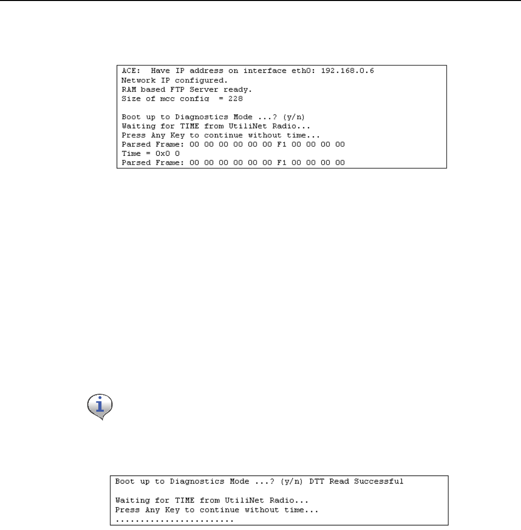
Landis+Gyr
Appendix C - Bench Testing
Network Concentrator User and Installation Guide 98-1013 Rev AF 102
network in the cross dock is not operational. Check the test TOP application, the UtiliNet Radio
connected to the test Take Out Point, UtiliNet antennas, etc.
Figure C.4 Broken
WAN
Inoperable WAN
This condition indicates that the communication between the UtiliNet Radio and the CPU is
inoperable (or) the UtiliNet radio is not configured correctly.
1. Configure the UtiliNet radio into the cross-dock test network as described above.
2. Make sure that the “MCCTIME” Helper DCW is loaded in the radio. A device control word
(DCW) is a program written in the UtiliNet programming language. DCW programs execute
within UtiliNet devices and provide the ability to control the device. The DCW sits on top of the
firmware and directs the radio when it is time to reboot or perform advanced math functions.
3. Power cycle the concentrator and check for the time again.
If the concentrator still does not pick time, then the unit has a inoperable WAN.
Figure C.5 Broken
WAN
CPU Configuration Check
To perform a check on the CPU configuration:
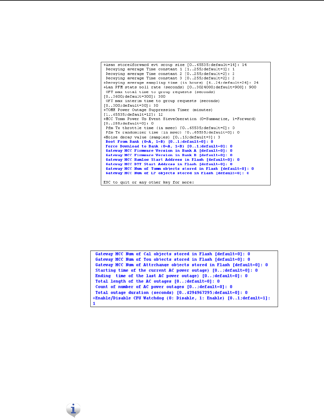
Landis+Gyr
Appendix C - Bench Testing
Network Concentrator User and Installation Guide 98-1013 Rev AF 103
1. From the Main Menu, go to the EEPROM configuration menu and verify the relevant EEPROM
configuration parameters.
2. From the concentrator EEPROM Configuration Menu display the configuration. Scroll down the
page that starts with “+Asap store&forward evt group size [0..65535;default=14]: 14".
3. Verify that the following highlighted parameters are set to 0.
Figure
C.6
CPU Configuration Check
4. Scroll down to the page which starts with the configuration item “Gateway Concentrator Num of
Cal objects stored in Flash [default=0]: 0".
5. Verify that the following highlighted parameters are set to the values as shown below.
Figure
C.7
Concentrator Parameters
LAN Health Check
The LAN health is determined from the concentrator's RAMLOG.
1. From the Concentrator Main Menu select option 'd'. The Concentrator Debug Menu appears.
2. Select option 'r', to get to Ramlog Menu.
Use option
“d”
to dump the
ra
mlog.
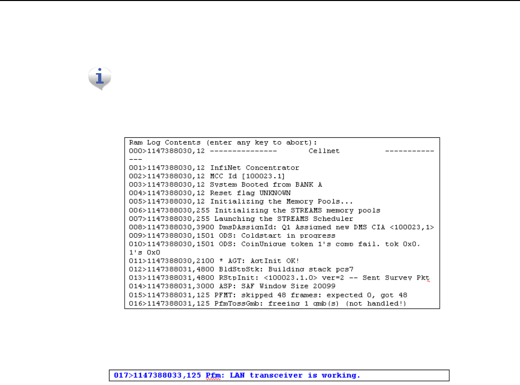
Landis+Gyr
Appendix C - Bench Testing
Network Concentrator User and Installation Guide 98-1013 Rev AF 104
3. Look into the ramlog contents for the message “Pfm: LAN transceiver is working.” This
indicates that the LAN transceiver is functional and the CPU is able to configure the LAN
transceiver.
If there are any messages like “Pfm: LAN transceiver is broken”, then the LAN
transceiver on this unit is not functional. If there is more than one instance of
th
e
above messages, then the LAN transceiver is being reset very
f
r
equ
e
n
t
ly.
Figure
C.8
Ram Log
Figure
C.9
LAN confirmation

Network Concentrator User and Installation Guide 98-1013 Rev AF 105
D
About Firmwar
e
The concentrator is an integrated unit consisting of
• UtiliNet Series III Integrated WAN Radio (IWR)
• BLT LAN Radio
• ConnectCore 9C CPU module
The ConnectCore 9C (CC9C) module is built on NetSilicon 32-bit NET+ARM technology. This is a
fully integrated system-on-chip, which provides embedded networking connectivity and additional
main processor performance and bandwidth to handle sophisticated embedded applications.
The features of the CC9C module are below:
• 32-bit NS9360 processor, operating at 155MHz
• 8MB Flash and 32 MB
• 10/100 Mbit Ethernet interface with on-board RJ-45 connector
• Four, high-speed serial ports. (Three ports out of four ports are used by the concentrator, the
fourth is for PC communications)
• Real Time Clock (Processor powered, no battery backup)
CC9C Serial Port Configuration
The CC9C provides a general purpose I/O (GPIO) interface. The GPIO lines corresponding to Serial
port A, B and C are connected to the console, UtiliNet WAN Radio and BLT LAN Radio.
The details
of the ConnectCore module are described in “ConnectCore™ 9C Hardware Reference. Part
number/version: 90000722_A Release date: June 2005."
All the serial ports are configured in UART mode. Except for baud rate, serial port parameters on all
the ports are configured for 8 Bits, No Stop Bits, 1 Parity Bit (8, N, 1) and handshake mode is 'none'.
The console port operates at 9600 baud, the WAN port operates at 19200 baud and the LAN port
operates at 19200 baud.
Startup
Firmware
Im
ages
The concentrator firmware consists of two image files, “rom.bin” and “image.bin”. The file
“rom.bin” is also referred to as the boot image. The file “image.bin” is also referred as the main/

Landis+Gyr
Appendix D - About Firmware
Network Concentrator User and Installation Guide 98-1013 Rev AF 106
application image. Both these images reside in the flash memory of the concentrator. The application
image resides in a compressed form in the Flash memory.
During the boot-up, these image files are loaded from the Flash memory into the RAM and executed
in the RAM. The following sections describe the concentrator boot-up.
Initialization and Boot Image Loading
The boot image consists of a ROM boot image that is executed directly from Flash, and a RAM boot
image that is stored in a compressed form in flash, and executed from RAM. The ROM boot image
executes at power up and it:
1. Executes the basic BSP initialization code to bring up the H/W.
2. Decompresses the RAM boot image from Flash to RAM.
3. Starts the RAM boot image.
Application Image Loading
The RAM boot image determines which application image to execute. This is based on the boot bank
configuration stored in the NVRAM/EEPROM section of the Flash memory. The RAM boot image
during its execution:
• Identifies the appropriate application image stored in flash.
• Decompresses the application image from Flash to RAM
• Starts the RAM application image.
Application Image Startup
The application image initializes all the necessary device divers and brings up the NET+OS
operating system. The NET+OS operating system after completing its initialization passes on the
control to the Concentrator Application. There are two execution modes (Diagnostics and
Application) in the concentrator. The following sections describe boot-up and provide details on the
execution modes.
Concentrator
Boot-Up
Normally, the NET+OS configuration option displays during the boot-up. During concentrator boot-
up, the network parameters required for configuring the TCP/IP are combined into the diagnostics
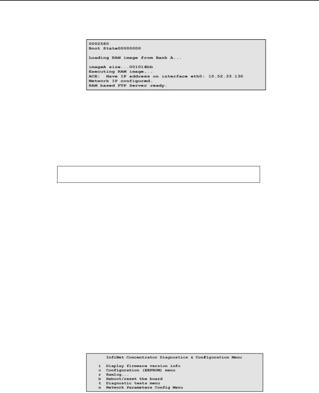
Landis+Gyr
Appendix D - About Firmware
Network Concentrator User and Installation Guide 98-1013 Rev AF 107
and configuration mode. The details of this configuration are explained in Concentrator Diagnostics
Mode. The following figure describes boot-up.
Figure D.1 Boot Up
Diagnostics
Mode
During the startup, the following question displays on the console:
Boot up to Diagnostics Mode ...? (y/n)y
If the input is 'y', the concentrator goes into diagnostics mode. The diagnostic mode has limited
functionality. The WAN port and the LAN port are not activated in this mode. This mode helps the
user to:
• Configure the concentrator;
• Browse and capture the Ramlog; and
• Perform diagnostics tests.
Diagnostics modes are described in the following sections.
Diagnostics
Mode
The diagnostics mode provides more diagnostics. In addition, this mode provides option to configure
the TCP/IP Network Parameters.
Figure D.2 Diagnostics
Mode
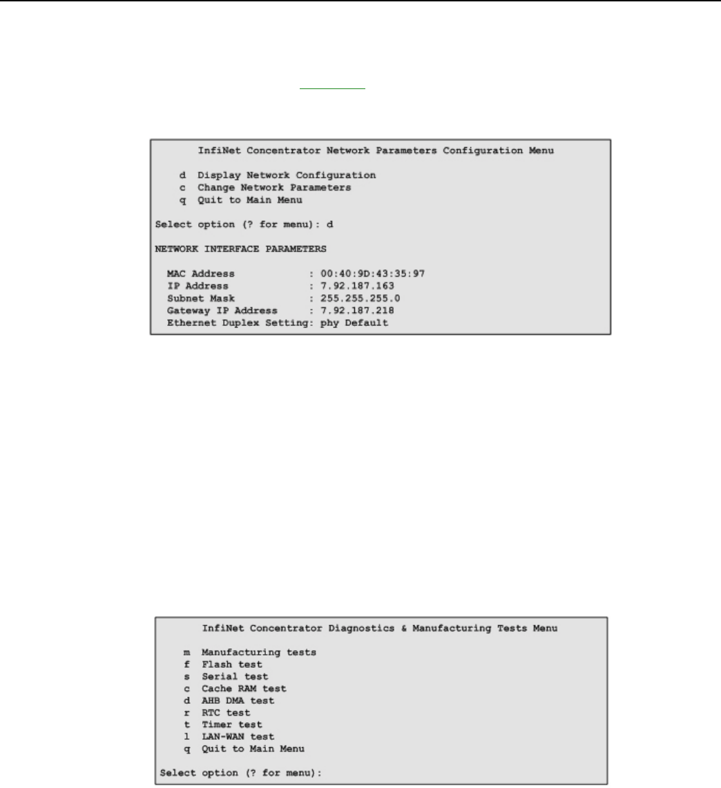
Landis+Gyr
Appendix D - About Firmware
Network Concentrator User and Installation Guide 98-1013 Rev AF 108
Network Parameters Configuration Menu
Option 'n' from the “Diagnostics and Configuration” menu displays the “Network Parameters
Configuration” menu, described in Figure D.3. In this menu, the TCP/IP network parameters are
displayed by using option'd', and the network parameters are configured by using option 'c'.
Figure D.3 Network Parameters Configuration
Menu
While configuring, the MAC Address should be set to the MAC address on the Connectcore
processor board. Appropriate values to the IP address, subnet mask, gateway IP address and the
Ethernet settings should be provided, to match the TCP/IP network corresponding to the local IT
environment.
Diagnostics Tests Menu
Option 't' from the “Diagnostics and Configuration” menu displays the “Diagnostics &
Manufacturing Tests” menu. This menu provides several test options. The menu options are
described in Figure 8: Diagnostics and Manufacturing Tests Menu.
Figure D.4 Diagnostics and Manufacturing Tests
Menu
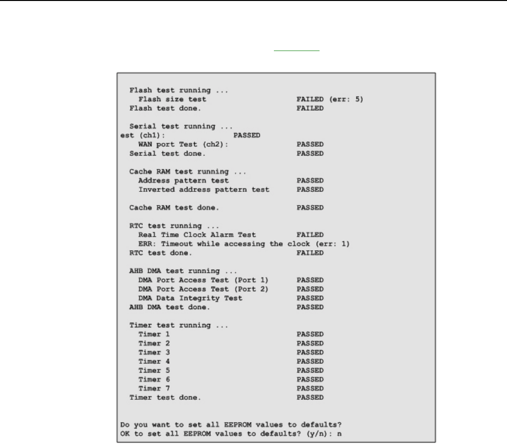
Landis+Gyr
Appendix D - About Firmware
Network Concentrator User and Installation Guide 98-1013 Rev AF 109
The option 'm' runs all the tests. This option is provided for use during the manufacturing. At the end
of this test, the EEPROM would be configured to default values (based on the user input).
The
details
of the tests performed are described in Figure D.4.
Figure D.5 Manufacturing tests
in
diagnostics
mode
Application
Mode
The application mode initializes the LAN, WAN and all the necessary device drivers for normal
operation. After initializing LAN and WAN, before all the system tasks are started, the concentrator
waits for time from the UtiliNet radio. The details of the time synchronization mechanism between
the concentrator and the UtiliNet WAN are explained below. Upon acquiring the TIME from the
UtiliNet radio, the concentrator gets into the normal application mode.
Landis+Gyr
Appendix D - About Firmware
Network Concentrator User and Installation Guide 98-1013 Rev AF 110
TIME from UtiliNet
Network
The concentrator has a Real Time Clock (RTC). However, this clock is processor powered, and has
no battery backup. Therefore, time is not remembered by the concentrator during resets. The
concentrator waits for the time from the UtiliNet Radio. The RTC is programmed with the latest time
from the concentrator.
Application
Troubleshooting
without
TIME
In the field, there may be instances where there is no WAN connectivity and, it may be required to
troubleshoot the concentrator. During boot-up, the following message is displayed on the console by
the concentrator.
Waiting for TIME from UtiliNet Radio...
Press Any Key to continue without time...
If any key is pressed during this wait period, the concentrator goes into the troubleshooting mode. In
this mode, the TIME is set a default hard coded time as shown below.
System Startup at Wed Oct 27 07:02:12 2004
A concentrator reboot/reset is required to get back from the
tr
oublesho
ot
ing
mode to the normal application mode
.
Persistent Data Storage
Data Storage
There are four persistent logical data storage in the concentrator. They are:
• EEPROM - This stores the system configuration information. The information stored in this is
not affected by the concentrator resets. The configuration parameters stored in the EEPROM are
captured in Appendix B - EEPROM Configuration Parameters;
• Device Tracking Table (DTT) - This is a persistent table. This table is used to store the endpoint
address and their performance metrics.
• Endpoint Database (aka ODE database) - This is the main database in the concentrator. This is a
object database. Every endpoint is represented in the form of an object.
• Ramlog - This is an in-memory file, which contains the system log. This file is preserved over
the resets.
All these persistent elements are stored in the flash memory. The EEPROM is stored in the last 64K
segment of the Flash memory. Rest of the data elements is stored in the Data Storage area of Flash
memory.

Landis+Gyr
Appendix D - About Firmware
Network Concentrator User and Installation Guide 98-1013 Rev AF 111
Impact of Boot-up on Data Storage
The concentrator boot-up/reset impacts the data storage. The nature of the impact varies based on the
type of the boot-up. There are three kinds of boot-up:
• Cold Boot - DTT is cleaned up. ODE is cleaned up. The concentrator will not remember any
endpoints.
• Warm boot - DTT is intact. ODE is cleaned up. The concentrator remembers the endpoints it
heard. However, there are no database objects corresponding to them.
• Hot Boot - DTT is intact; and ODE is intact.
Capacity
The following table describes the data storage capacity in concentrators.
Table
D-1.
Concentrator Capacity
Type
Concentrator
Meter Endpoints (Cellnet 1-way meter module)
5000
ASAP objects
300
Load Profile (LP) Objects
3000
Note: Only 1000 TOMMs can be set on Load
Profile.
DTT entries
40000
Calendar objects
20
Time of Use (TOU) objects
20
Ramlog size
1024 x 80 bytes
Cycling Power
To immediately reboot the concentrator, perform the following steps:
1. Disconnect the AC cable from its connection on the concentrator.
Disconnect the cable from the concentrator end, not the AC power source end.
Do not disconnect the battery cable. If you cannot reach the AC cable on
th
e
concentrator end, then unplug at the source. You must wait three days for
t
h
e
battery to completely drain before you reconnect this
c
a
ble.
2. Wait five seconds.
3. Re-connect the AC power cable to the concentrator.

E
About Programming and
Diagnostic Cables
Network Concentrator User and Installation Guide 98-1013 Rev AF 113
Landis+Gyr offers multiple cable options for performing system upgrades and configuration. The
following table outlines tasks each cable can perform.
Table E-1. Update Cables
Cable
LPP
Console
Ethernet
19-1185
Do not plug this
cable into a Phase I
Concentrator (26-
1129 or 26-1163).
Upload DCWs,
Upload new
firmware, and
configure the UtiliNet
radio inside the
concentrator.
Configure EEPROM
settings in the
concentrator CPU,
which includes the
Concentrator Net and
Node ID (aka MCC
Net and Node), Event
Manager Net, and
Node settings.
Can do a direct FTP
download of
concentrator CPU
firmware via cable
connection. Use a
router, computer, and
Ethernet cables.
19-1126
Upload DCWs,
Upload new
firmware, and
configure the UtiliNet
radio inside the
concentrator.
Configure EEPROM
settings in the
concentrator CPU,
which includes the
Concentrator Net and
Node ID (aka MCC
Net and Node), Event
Manager Net, and
Node settings.
No Ethernet
connectivity. Perform
upgrades over the air.
You must have a WAN
network setup with a
Take Out Point
(TOP), and the
Cellnet
system running on
the system controller.
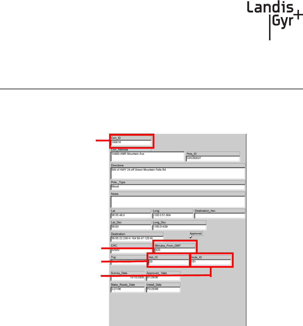
F
Sample Survey Sheet
Network Concentrator User and Installation Guide 98-1013 Rev AF 115
A sample survey sheet appears below this paragraph. Your utility may use a different format. This
illustration calls out fields to update via Hyperterminal during configuration.
Concentrator ID
Minutes from GMT
Net ID
Node
ID
Figure
F - 1.
Sample survey
sheet

Network Concentrator User and Installation Guide 98-1013 Rev AF 117
G
Field Upgrade to DCW 1.16F
This appendix contains information about upgrading Concentrator Gridstream radios that are within
the field to DCW version 1.16F. It covers the following sections:
• Changing 9QPR-based MCC to a Gridstream-based Concentrator
• Upgrading DCW and Losing Default Destination
Changing 9QPR-based MCC to a
Gridstr
eam-based
Concentrator
When replacing a 9QPR-based MCC with a RF mesh-based Concentrator, communication between
host and the new Concentrator is established as soon as the DCW begins sending Concentrator
Registration Messages. Once the host receives a Concentrator Registration Message, through
whichever Collector the DCW has chosen, the host will discover the device.
Upgrading DCW and Losing Default Destination
Before you get started upgrading, make sure you complete the following recommended steps to
avoid protection errors as well as other upgrade errors.
1. Read the current DCW’s default destination.
Verify that the number is identical to the current DCW. Failure to do so
can cause major read
pr
o
b
le
ms.
2. Load 1.16F into the radio.
3. Restore the address to the new DCW.
Upgrade Issues
Default Destination
If you override or lose the default destination, the DCW waits for the installer to assign a destination.
If a designation is not assigned, the DCW will query its neighbors and select the nearest collector. A
Concentrator Registration Message is sent through the selected collector with the shortest response
time. This will likely be the same Concentrator it was sending to before. If it is a new Concentrator
that is attached to the same System Controller as the original one, things will still work. System
controllers are randomly associated with Concentrators. There is no guarantee that a Collector within

Appendix G - Field Upgrade to DCW 1.16F
Landis+Gyr
Network Concentrator User and Installation Guide 98-1013 Rev AF 118
the neighborhood will be associated with the same System Controller as the Collector next door. If a
utility is large enough to have a lot of System Controllers in use, then it is likely the change to a
different Collector will result in a change to the System Controller. However, if the DCW completes
the neighbor-query process in a timely-manner, the host will straighten the reassignment once it sees
the Concentrator Registration Message.
The Concentrator discovery process time can be between
15
-
30
minutes
If the host sends the Concentrator CPU a message before the new default destination is assigned, it
will use the Collector within the database. The DCW automatically accepts the Collector WAN
address as the default destination as long as the message is received before the default destination is
assigned.
Self-Assigned Destination
The best way to prevent unprocessed messages from interfering with data reads, is to shut down the
host registration processing code during scheduled reads. The DCW will continue to send
Concentrator Registration Messages once every 15 minutes until the host responds. If the DCW
successfully self assigns a destination, a query from the host to the Concentrator CPU is received to
not automatically change the destination. To change the destination, you must manually change it. If
the destination change fails while on a different System Controller, the meter read data that is going
to an incorrect System Controller is still processed, and then put into the database. The meter
discovery events from that Concentrator will not work.
To avoid non-working meter discovery events, L+G recommends using
the normal Concentrator repoint process to address the Conc
en
tr
ator
to the correct System Con
t
r
o
lle
r.
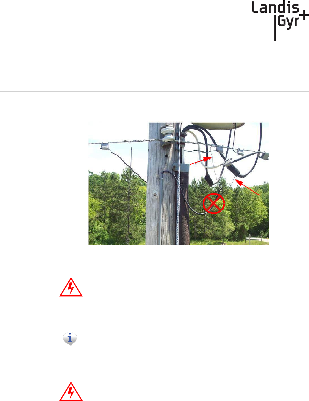
Network Concentrator User and Installation Guide 98-1013 Rev AF 119
H
Power Cable Installation
Power Connection and Termination
Figure
H - 1.
Improper Power
Termination
If
using
the 105704-000, 105704-001, 105704-002, or 105704-003 cables, the
end of the cable opposite the connector (the unterminated end) must be
installed
in a
junction
box or other suitable
enclosure.
These cables are not
recommended for new
installations.
See Table 4-1 for suggested parts.
The older version decorative light pole kits use 105704-002 cables. Please
observe standard precautions unless installing with the 19-2273 cables, which
are in the current kits. Use standard procedures when installing 105604-XXX
cables.
If
using
the 105704-000, 105704-001, 105704-002, or 105704-003 cables, the
end of the cable opposite the connector (the unterminated end) must be
installed in a junction box or other suitable enclosure.
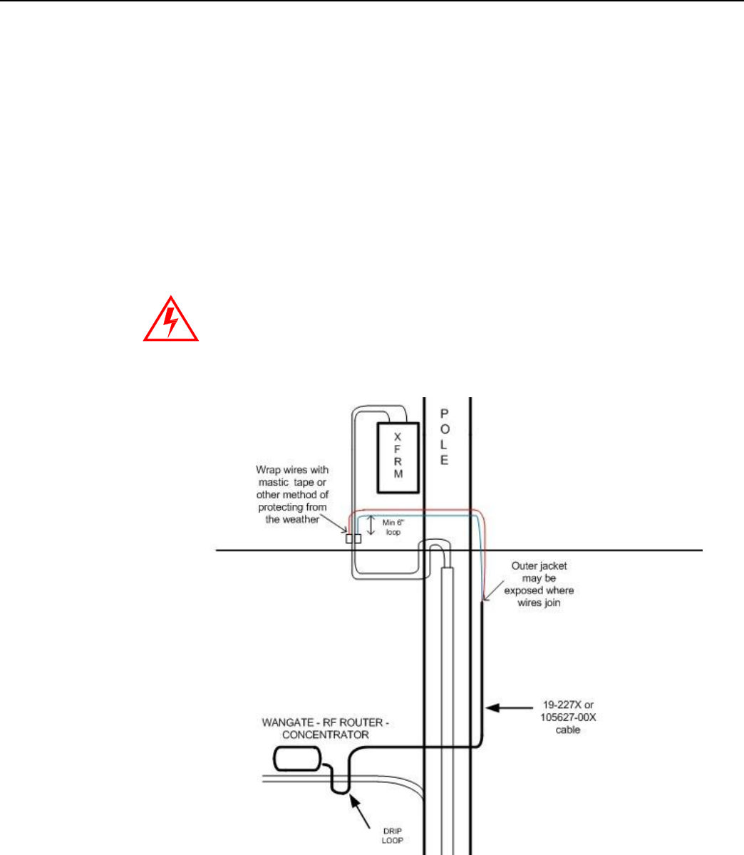
Appendix H - Power Cable Installation
Landis+Gyr
Network Concentrator User and Installation Guide 98-1013 Rev AF 120
Recommendations
Water-Blocking Connections
When 19-227X or 105627-00X cables are used, they do not have to be terminated inside a junction
or disconnect box. Protect the wire junction with mastic tape (or some other method).
In published examples, Collector cables are shown going through conduit. Conduit is not
required
for
Concentrators.If a junction box is used, the entrance to the junction box should be through a
clamp at the bottom of the junction box. Junction boxes do not have a part number and are available
through local vendors. As always, electrical connections need to meet the requirements of the local
utility and local ordinances.
The figure below shows an installation of a Concentrator without using a junction box.
This installation diagram is for water blocking cable only. Do not install
standard 105704-XXX “old style” cables as shown in the following figure.
Figure
H - 2.
Suggested Power Termination
for
Water Blocking
Lines

Appendix H - Power Cable Installation
Landis+Gyr
Network Concentrator User and Installation Guide 98-1013 Rev AF 121
Non-Water-Blocking Connections
When existing 105704-XXX cables are used, they must be terminated inside a junction or disconnect
box. The inner wires cannot be exposed until the 105704-XXX cable enters the enclosure. Once
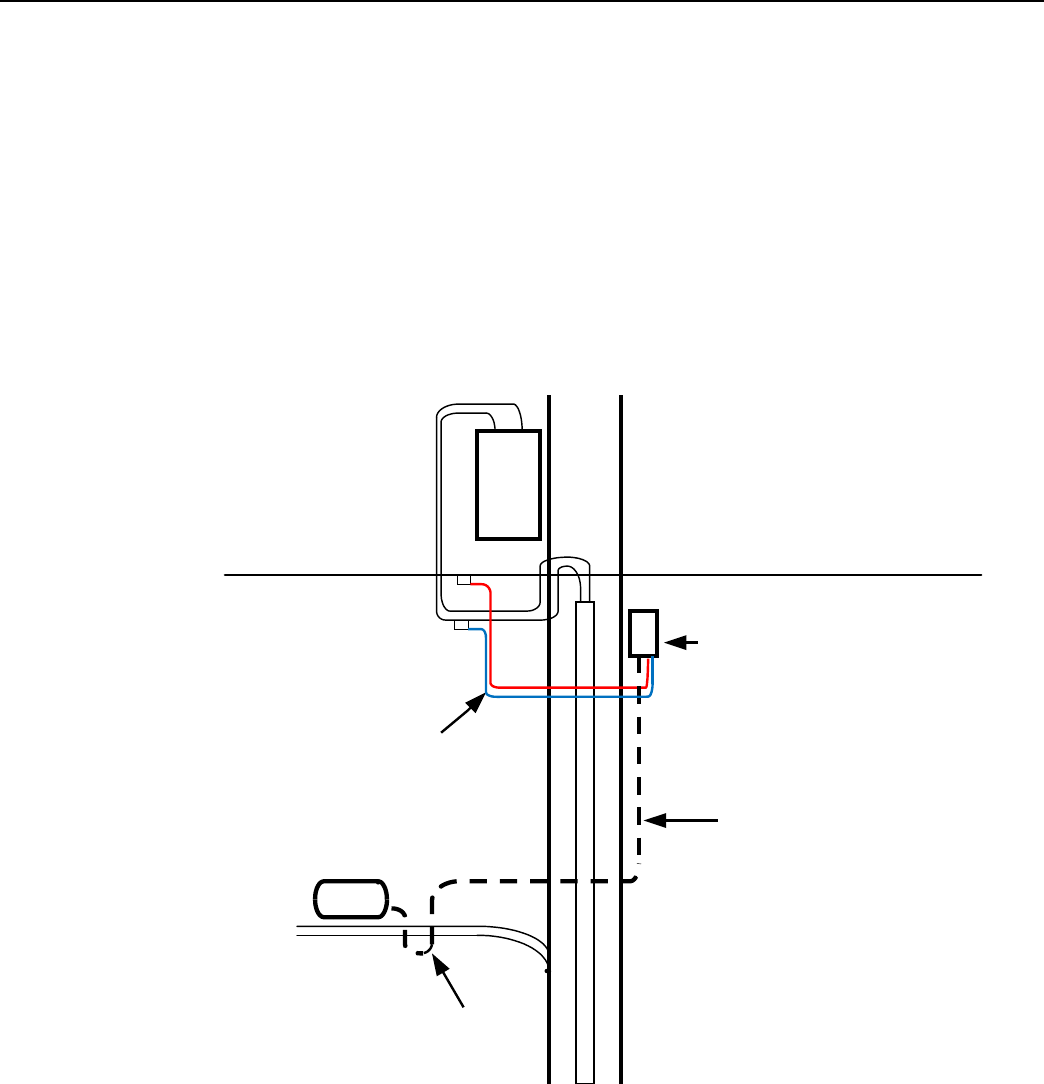
Network Concentrator User and Installation Guide 98-1013 Rev AF 122
Landis+Gyr Appendix H - Power Cable Installation
inside the box, connect the power leads to wires going to the mains per local practice. Connections to
the mains must use UV-stable wiring. As long as the wire is UV-stable and rated for outdoor use, the
wire model and manufacturer may be selected by the programs. Part number 18-1033 wire is
acceptable and recommended.
In published examples, Collector cables are shown going through conduit. Conduit is not
required
for
Concentrators, but the entrance to the junction box should be through a clamp at the bottom
of
the
junction box. Junction boxes do not have a part number and are available through local vendors.
As always, electrical connections need to meet the requirements of the local utility and local
ordinances.
The following diagram shows an installation using a junction box with a Concentrator. If
105704-XXX cable is used, then this installation procedure is required.
P
O
X
F L
R E
M
JUNCTION OR
DISCONNECT BOX
UV
STABLE
WIRES
105704-XXX CABLE
CONCENTRATOR
DRIP
LOOP
Figure
H - 3.
Suggested Power Termination
for
Non-Water Blocking
Lines
If the 105627-XXX cable is used, then the cable can go directly to the mains, provided drip loops are
made at the point of contact with the mains and at the Concentrator. The drip loop at the point of
attachment to the mains should rise above the level of the point of attachment.

Glossary
Network Concentrator User and Installation Guide 98-1013 Rev AF 124
BSP Board Support Package
C&I Commercial and Industrial meters; usually solid state meters with demand notes
Concentrator Device that collects data and events from radio frequency local area network (RF
LAN) devices for storage in the object database; communicates with the
Collector (Take Out Point, or TOP) to forward the metering data.
DCW A Device Control Word (DCW) is a not actually a word, but a program written
in the UtiliNet programming language. DCWs execute within UtiliNet devices
and provide the ability to control the device. The DCW sits on top of the
firmware and directs the radio to perform tasks such as reboot or other, more
advanced, functions.
Demand Meter rate
DTT Device Tracking Table: The table on the Concentrator that stores information
about module discovery and health statistics.
EEPROM Electrically Erasable Programmable Read-Only Memory
Gridstream IWR Integrated WAN Radio. Used to communicate remotely to the network.
LAN Local Area Network, consists of endpoints and RF link between endpoints and
gathering devices such as Concentrators.
MAC Media Access Controller used while configuring network parameters.
MapInfo Software that maps devices and data regarding those devices in the network.
Network Concentrator See Concentrator
NVRAM Non-Volatile Random Access Memory
OCDB Operations Center DataBase. Endpoint Management system that reports to
network, exchanges information with the utility.
OTA Over the Air, versus a direct or indirect (router) serial cable connection.
Personal Protection Equipment also called Personal Protective Equipment, all necessary equipment used for
worker safety while performing work on utility metering equipment as defined
in this manual.
Ping An “Echo” command travels to a specified device and then waits for a response.
The result is a report that displays the success or failure, usually a report back of
a timed response in seconds, of the intended action.

Network Concentrator User and Installation Guide 98-1013 Rev AF 125
RAM Random Access Memory
RIMS Retrofit Information Management System, an Oracle program managing the
shop floor assembly and programming of modules, also stands for myriad of
data tables. Exchanges information with OCDB.
RPT Revenue Protection Technician, utility employee responsible for identifying and
taking corrective action on theft of service cases.
SNR Signal to noise ratio: Comparison of the usable signal being transmitted to the
undesired signal, usually expressed in decibels; a quality measure of a
transmission.
TOP Take Out Point; also called a Collector.
TOU Time of Use. Specific meter rate where the usage is captured in intervals.
WAN Wide Area Network, consists of data gathering devices like Concentrators and
endpoints.
XD Cross-Dock

Index
Network Concentrator User and Installation Guide 98-1013 Rev AF 126
Numerics
19200 baud 105
32-bit NS9360 processor 105
9600 baud 105
A
AC power cable 30, 37, 43
Antenna Options 29
Appendix C Transmission Verification 93, 97
Application 110
Application Image Loading 106
Application Image Startup 106
Application Mode 109
Application Troubleshooting without TIME 110
B
Bench Testing 91, 99, 105, 113
BLT LAN Radio 105
BSP 106
Bucket Truck 12
C
Capacity 111
CC9C Serial Port Configuration 105
CC9C) 105
Class B digital device 97
Compliance 97
Concentrator Download Menu 66–67
Concentrator Installation 29
Concentrator ping test 62
Concentrator Verification 67
Configuration 100
ConnectCore 9C CPU module 105
Console/LAN Packet Protocol cable 100
CPU configuration 102
D
Data Storage 110
DCW 84, 102
Device Tracking Table 110
Diagnostics Mode 107
Diagnostics Tests Menu 108
Drip Loop 30
DTT 110
E
EEPROM 103, 109–110
Endpoint Database 110
Error messages 9
Ethernet interface 105
F
FCC 97, 119–120
Field Configuration 15
Firmware Images 105
Flash 106
G
Glossary 123–124
Glossary Title 123
I
I/O interface 105
ID Badges 12
Ideal WAN 101
Impact of Boot-up on Data Storage 111
Inconsistent WAN 101
Initialization and Boot Image Loading 106
Inoperable WAN 102
Install Material 13
Installation Sheet 29
IWR 105
K
Kit

Index
Landis+Gyr
Network Concentrator User and Installation Guide 98-1013 Rev AF 127
22-1072
46
22-2319
38
26-1046
16
26-1061
17
26-1139
52, 57
28-1012
32
Concentrator 32
Concentrator Metal Pole Mounting 37
Concentrator Phase II Battery Pack Replacement 57
Concentrator Programming 16, 31
Light Pole Mounting 31
Metal Pole Mounting 31
Part Numbers 31
Wood Pole Mounting 31, 34
L
19-2200 33, 45
19-2215 37
22-0375 37, 45
22-0421 34, 38, 46
22-0453 38
22-0587 38
22-1062 38
22-1071 34
LAN antenna 29, 36, 41, 43
LAN Health Check 103
Landis+Gyr Technical Support 9
M
MCCTIME Helper DCW 17, 102
N
Network Configuration Manager 17
Network ID 17, 100
Network Parameters Configuration Menu 108
O
ODE database 110
Operations 61
P
Part 15 of the FCC Rules 97
Performance 93
Permits 12
Persistent Data Storage 110
Phase II
Concentrator Capacity 111
PN
01-1039 57
01-1239 32
101676-025 57
101849-100 57
101983-025 34, 37, 46
103826-000 30, 45
105628-000 16
106119-000 32
16-0214 37, 40
19-1013 34, 45
19-1027 16
19-1126 100, 113
19-1135 16–17
19-1185 16, 113
28-1031 46
28-1061 39, 46
28-1090 38, 40
28-2315 38
45-1046 16, 31
45-1048 31, 34, 36
45-1049 31, 45
45-1050 31, 37
45-1055 31
Power Cable Preparation 30
Power Requirements 29
Power Statistics 94
Publication number 10
R
RAM 106
RAMLOG 103
Ramlog 110
Real Time Clock 105, 110
Replacing the Battery Pack 58
RF Exposure 97
RF Mesh Network 7
ROM 106
S
Serial ports 105
Site Survey 12
Startup 105
Supervision 12
T
TCP/IP 107
technical support 9
Test Bench 99
TIME from UtiliNet Network 110

Network Concentrator User and Installation Guide 98-1013 Rev AF 128
Landis+Gyr Index
Timeline 12
Titles
Glossary
123
Tool List 13
Troubleshooting 91
U
UART 105
UtiliNet Series III Integrated WAN Radio 105
W
WAN antenna 29, 36, 41–42
WAN Health Check 101