Landis Gyr Technology ER6R1S1 Gridstream ResGas Module User Manual XX XXXX Exhibit Cover
Landis+Gyr Technology, Inc. Gridstream ResGas Module XX XXXX Exhibit Cover
UserManual.wiki
>
Landis Gyr Technology
>
ER6R1S1 User Manual
Users Manual
Navigation menu
Upload a User Manual
Namespaces
Wiki Guide
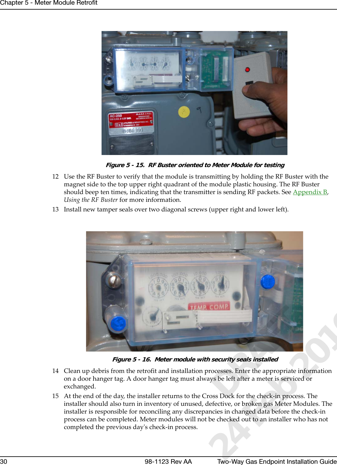
HTML
PDF
Info
Views
User Manual
Discussion / Help
Navigation
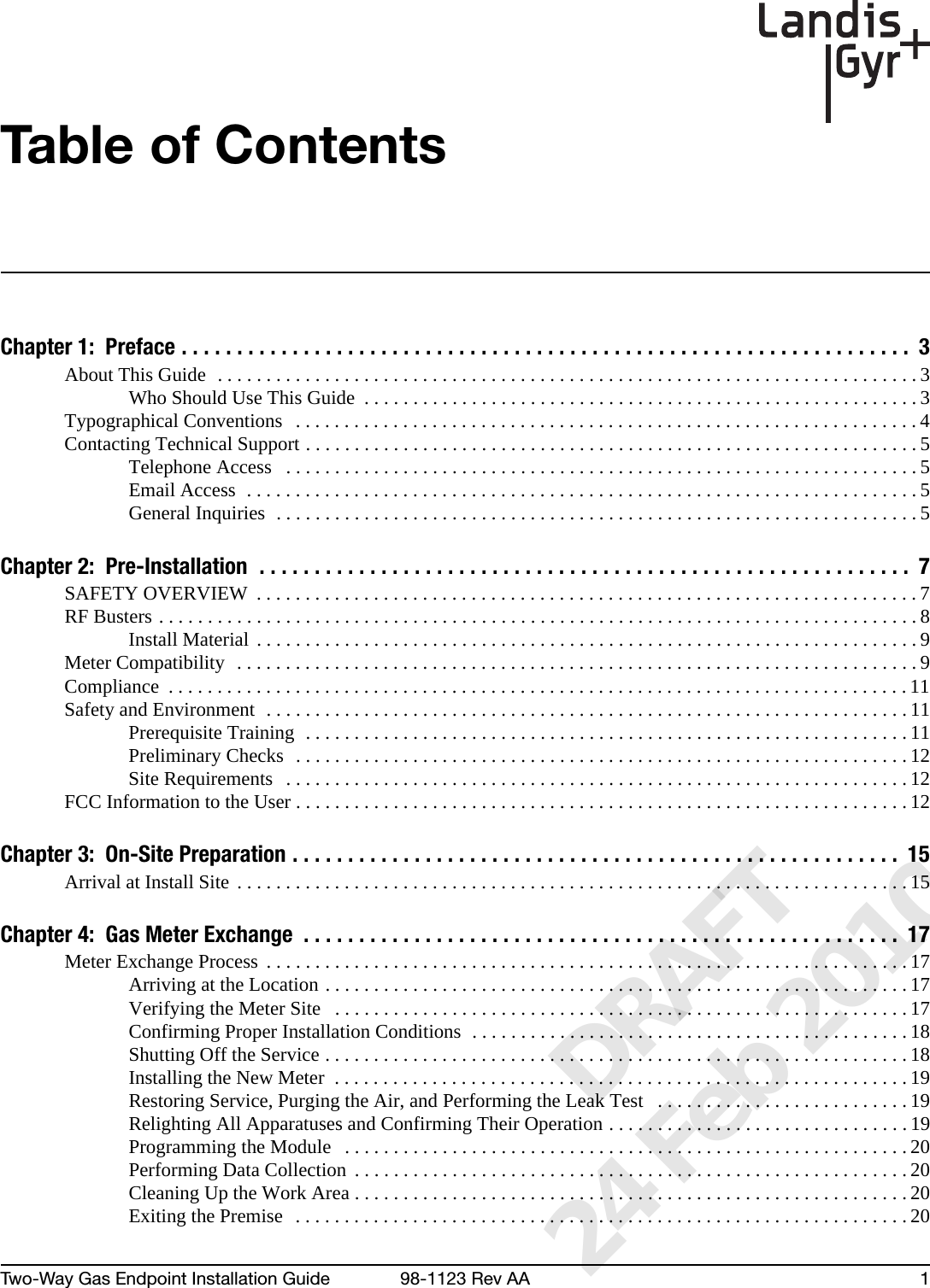
![Landis+Gyr Chapter 1 - PrefaceTwo-Way Gas Endpoint Installation Guide 98-1123 Rev AA 5Contacting Technical SupportLandis+Gyr technical support is available by telephone (888-390-5733) or email EëçäìíáçåëìééçêíKå~]ä~åÇáëÖóêKÅçãF. When you contact technical support, be prepared to give exact descriptions of:• The problem you encountered.• What happened and what you were doing when the problem occurred• How you tried to solve the problem• The exact text of any error messagesTelephone AccessTechnical support is available Monday through Friday from 8:00 a.m. to 5:00 p.m. (ET) by calling 888-390-5733. If all support technicians are helping other customers, your call will be routed to the Landis+Gyr Support voice mail system.Leave a brief message that includes the following information:• Your name• Your company’s name• Your telephone numberA support technician will return your call as soon as possible within normal business hours. Technicians return all calls in the order that they are received.Email AccessIf you prefer, you may email a description of your problem to:ëçäìíáçåëìééçêíKå~]ä~åÇáëÖóêKÅçãA support technician will return your email as soon as possible within normal business hours. Technicians return all emails in the order that they are received.General InquiriesYour feedback is important in helping to provide the most accurate and high-quality information. If you want to reach a Landis+Gyr representative, do one of the following:• Telephone: 678-258-1500• Fax: 678-258-1550You can also mail your comments or inquiries to:Landis+GyrAttn:CustomerSupport30000MillCreekAvenueSuite100Alpharetta, GA 30022 DRAFT 24 Feb 2010](https://usermanual.wiki/Landis-Gyr-Technology/ER6R1S1/User-Guide-1246461-Page-8.png)
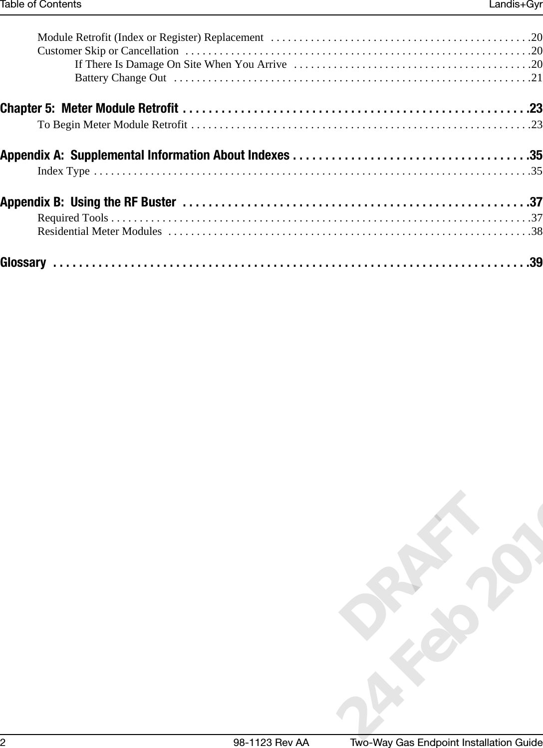
![Chapter 1 - Preface Landis+Gyr6 98-1123 Rev AA Two-Way Gas Endpoint Installation GuideOrdering PublicationsYou can order publications from your sales representative. To order additional copies of this manual, use order number:98‐1123RevAAPublication CommentsLandis+Gyr welcomes your feedback and comments. If you have comments or suggestions for improving this publication, please communicate your comments about this publication, its organization, or subject matter, with the understanding that we may use or distribute whatever information you supply in any way we believe appropriate without incurring any obligation to you.You can send comments via email, conventional mail, or fax.. If you would like a reply, please include your contact information:•Name• Telephone number or fax number• Email address• Company name and addressBe sure to include the following information along with your comment:• Title and number of this manual• Page number or topic related to your commentTo send your comments via... Use this contact information...bã~áä =ëçäìíáçåëìééçêíKå~]ä~åÇáëÖóêKÅçã`çåîÉåíáçå~ä=ã~áä i~åÇáëHdóêI=PMMMM=jáää=`êÉÉâ=^îÉKI=pìáíÉ=NMMI=^äéÜ~êÉíí~I=d^=PMMOOc~ñ ESTUF=ORUJNRRM DRAFT 24 Feb 2010](https://usermanual.wiki/Landis-Gyr-Technology/ER6R1S1/User-Guide-1246461-Page-9.png)