Landis Gyr Technology ER6R1S1 Gridstream ResGas Module User Manual XX XXXX Exhibit Cover
Landis+Gyr Technology, Inc. Gridstream ResGas Module XX XXXX Exhibit Cover
Users Manual

5015 B.U. Bowman Drive Buford, GA 30518 USA Voice: 770-831-8048 Fax: 770-831-8598
Certification Exhibit
FCC ID: R7PER6R1S1
FCC Rule Part: 15.247
ACS Report Number: 09-0409.W03.11.A
Manufacturer: Cellnet Technology Inc.
Model: Gridstream ResGas
Manual

LANDIS+GYR CONFIDENTIAL INFORMATION
Gridstream M120 Two-Way
Gas Endpoint Installation
Guide
98-1123 Rev AA
DRAFT
24 Feb 2010
Limitation on Warranties and Liability
Information in this document is subject to change without notice. This manual or any part of it thereof may not be
reproduced in any form unless permitted by contract or by written permission of Landis+Gyr.
In no event will Landis+Gyr be liable for any incidental, indirect, special, or consequential damages (including lost
profits) arising out of or relating to this publication or the information contained in it, even if Landis+Gyr has been
advised, knew, or should have known of the possibility of such damages.
© 2010 Landis+Gyr. All Rights Reserved.
Trademarks
Cellnet® is a registered trademark of Cellnet Innovations, Inc.
Other brands or product names are the trademarks or registered trademarks of their respective holders.s.
DRAFT
24 Feb 2010

Two-Way Gas Endpoint Installation Guide 98-1123 Rev AA 1
Table of Contents
Chapter 1: Preface . . . . . . . . . . . . . . . . . . . . . . . . . . . . . . . . . . . . . . . . . . . . . . . . . . . . . . . . . . . . . . . . . . 3
About This Guide . . . . . . . . . . . . . . . . . . . . . . . . . . . . . . . . . . . . . . . . . . . . . . . . . . . . . . . . . . . . . . . . . . . . . . . . 3
Who Should Use This Guide . . . . . . . . . . . . . . . . . . . . . . . . . . . . . . . . . . . . . . . . . . . . . . . . . . . . . . . . . 3
Typographical Conventions . . . . . . . . . . . . . . . . . . . . . . . . . . . . . . . . . . . . . . . . . . . . . . . . . . . . . . . . . . . . . . . . 4
Contacting Technical Support . . . . . . . . . . . . . . . . . . . . . . . . . . . . . . . . . . . . . . . . . . . . . . . . . . . . . . . . . . . . . . . 5
Telephone Access . . . . . . . . . . . . . . . . . . . . . . . . . . . . . . . . . . . . . . . . . . . . . . . . . . . . . . . . . . . . . . . . . 5
Email Access . . . . . . . . . . . . . . . . . . . . . . . . . . . . . . . . . . . . . . . . . . . . . . . . . . . . . . . . . . . . . . . . . . . . . 5
General Inquiries . . . . . . . . . . . . . . . . . . . . . . . . . . . . . . . . . . . . . . . . . . . . . . . . . . . . . . . . . . . . . . . . . . 5
Chapter 2: Pre-Installation . . . . . . . . . . . . . . . . . . . . . . . . . . . . . . . . . . . . . . . . . . . . . . . . . . . . . . . . . . . 7
SAFETY OVERVIEW . . . . . . . . . . . . . . . . . . . . . . . . . . . . . . . . . . . . . . . . . . . . . . . . . . . . . . . . . . . . . . . . . . . . 7
RF Busters . . . . . . . . . . . . . . . . . . . . . . . . . . . . . . . . . . . . . . . . . . . . . . . . . . . . . . . . . . . . . . . . . . . . . . . . . . . . . . 8
Install Material . . . . . . . . . . . . . . . . . . . . . . . . . . . . . . . . . . . . . . . . . . . . . . . . . . . . . . . . . . . . . . . . . . . . 9
Meter Compatibility . . . . . . . . . . . . . . . . . . . . . . . . . . . . . . . . . . . . . . . . . . . . . . . . . . . . . . . . . . . . . . . . . . . . . . 9
Compliance . . . . . . . . . . . . . . . . . . . . . . . . . . . . . . . . . . . . . . . . . . . . . . . . . . . . . . . . . . . . . . . . . . . . . . . . . . . .11
Safety and Environment . . . . . . . . . . . . . . . . . . . . . . . . . . . . . . . . . . . . . . . . . . . . . . . . . . . . . . . . . . . . . . . . . . 11
Prerequisite Training . . . . . . . . . . . . . . . . . . . . . . . . . . . . . . . . . . . . . . . . . . . . . . . . . . . . . . . . . . . . . . 11
Preliminary Checks . . . . . . . . . . . . . . . . . . . . . . . . . . . . . . . . . . . . . . . . . . . . . . . . . . . . . . . . . . . . . . .12
Site Requirements . . . . . . . . . . . . . . . . . . . . . . . . . . . . . . . . . . . . . . . . . . . . . . . . . . . . . . . . . . . . . . . .12
FCC Information to the User . . . . . . . . . . . . . . . . . . . . . . . . . . . . . . . . . . . . . . . . . . . . . . . . . . . . . . . . . . . . . . . 12
Chapter 3: On-Site Preparation . . . . . . . . . . . . . . . . . . . . . . . . . . . . . . . . . . . . . . . . . . . . . . . . . . . . . . . 15
Arrival at Install Site . . . . . . . . . . . . . . . . . . . . . . . . . . . . . . . . . . . . . . . . . . . . . . . . . . . . . . . . . . . . . . . . . . . . . 15
Chapter 4: Gas Meter Exchange . . . . . . . . . . . . . . . . . . . . . . . . . . . . . . . . . . . . . . . . . . . . . . . . . . . . . . 17
Meter Exchange Process . . . . . . . . . . . . . . . . . . . . . . . . . . . . . . . . . . . . . . . . . . . . . . . . . . . . . . . . . . . . . . . . . . 17
Arriving at the Location . . . . . . . . . . . . . . . . . . . . . . . . . . . . . . . . . . . . . . . . . . . . . . . . . . . . . . . . . . . . 17
Verifying the Meter Site . . . . . . . . . . . . . . . . . . . . . . . . . . . . . . . . . . . . . . . . . . . . . . . . . . . . . . . . . . .17
Confirming Proper Installation Conditions . . . . . . . . . . . . . . . . . . . . . . . . . . . . . . . . . . . . . . . . . . . . . 18
Shutting Off the Service . . . . . . . . . . . . . . . . . . . . . . . . . . . . . . . . . . . . . . . . . . . . . . . . . . . . . . . . . . . . 18
Installing the New Meter . . . . . . . . . . . . . . . . . . . . . . . . . . . . . . . . . . . . . . . . . . . . . . . . . . . . . . . . . . . 19
Restoring Service, Purging the Air, and Performing the Leak Test . . . . . . . . . . . . . . . . . . . . . . . . . . 19
Relighting All Apparatuses and Confirming Their Operation . . . . . . . . . . . . . . . . . . . . . . . . . . . . . . . 19
Programming the Module . . . . . . . . . . . . . . . . . . . . . . . . . . . . . . . . . . . . . . . . . . . . . . . . . . . . . . . . . .20
Performing Data Collection . . . . . . . . . . . . . . . . . . . . . . . . . . . . . . . . . . . . . . . . . . . . . . . . . . . . . . . . . 20
Cleaning Up the Work Area . . . . . . . . . . . . . . . . . . . . . . . . . . . . . . . . . . . . . . . . . . . . . . . . . . . . . . . . .20
Exiting the Premise . . . . . . . . . . . . . . . . . . . . . . . . . . . . . . . . . . . . . . . . . . . . . . . . . . . . . . . . . . . . . . . 20
DRAFT
24 Feb 2010

Table of Contents Landis+Gyr
2 98-1123 Rev AA Two-Way Gas Endpoint Installation Guide
Module Retrofit (Index or Register) Replacement . . . . . . . . . . . . . . . . . . . . . . . . . . . . . . . . . . . . . . . . . . . . . .20
Customer Skip or Cancellation . . . . . . . . . . . . . . . . . . . . . . . . . . . . . . . . . . . . . . . . . . . . . . . . . . . . . . . . . . . . .20
If There Is Damage On Site When You Arrive . . . . . . . . . . . . . . . . . . . . . . . . . . . . . . . . . . . . . . . . . .20
Battery Change Out . . . . . . . . . . . . . . . . . . . . . . . . . . . . . . . . . . . . . . . . . . . . . . . . . . . . . . . . . . . . . . .21
Chapter 5: Meter Module Retrofit . . . . . . . . . . . . . . . . . . . . . . . . . . . . . . . . . . . . . . . . . . . . . . . . . . . . . .23
To Begin Meter Module Retrofit . . . . . . . . . . . . . . . . . . . . . . . . . . . . . . . . . . . . . . . . . . . . . . . . . . . . . . . . . . . .23
Appendix A: Supplemental Information About Indexes . . . . . . . . . . . . . . . . . . . . . . . . . . . . . . . . . . . . .35
Index Type . . . . . . . . . . . . . . . . . . . . . . . . . . . . . . . . . . . . . . . . . . . . . . . . . . . . . . . . . . . . . . . . . . . . . . . . . . . . .35
Appendix B: Using the RF Buster . . . . . . . . . . . . . . . . . . . . . . . . . . . . . . . . . . . . . . . . . . . . . . . . . . . . . .37
Required Tools . . . . . . . . . . . . . . . . . . . . . . . . . . . . . . . . . . . . . . . . . . . . . . . . . . . . . . . . . . . . . . . . . . . . . . . . . .37
Residential Meter Modules . . . . . . . . . . . . . . . . . . . . . . . . . . . . . . . . . . . . . . . . . . . . . . . . . . . . . . . . . . . . . . . .38
Glossary . . . . . . . . . . . . . . . . . . . . . . . . . . . . . . . . . . . . . . . . . . . . . . . . . . . . . . . . . . . . . . . . . . . . . . . . . .39
DRAFT
24 Feb 2010

1
Two-Way Gas Endpoint Installation Guide 98-1123 Rev AA 3
Preface
This guide describes the installation process for the Landis+Gyr Gridstream M120 Two-Way
Residential Meter Gas Module.
Any training provided directly to installers by the utility or by the Landis+Gyr project management
team takes precedence over this guide, as long as it does not involve altering the meter module
retrofit process.
About This Guide
This edition of the Landis+Gyr Gridstream M120 Two-Way Residential Meter Gas Module
Installation Guide provides:
–basicinformationofthefieldinstallation,retrofit,andexchangeprocedureusedfor
residentialgasmeters.
–basicsafetyguidelinesanddetailedinstructionsforinstallingandexchangingofgasmeters.
Who Should Use This Guide
This guide is intended for use by utility employees responsible for installing meters and module
retrofitting to already installed meters. It does not assume an expert level of industry or computer
knowledge. This guide does assume that you are familiar with basic:
–utilityoperations.
– terminologyofyourindustry.
– proceduresforperformingbasicHandheldoperations.
DRAFT
24 Feb 2010
Chapter 1 - Preface Landis+Gyr
4 98-1123 Rev AA Two-Way Gas Endpoint Installation Guide
Typographical Conventions
This section describes the conventions used in this guide to make finding and understanding
information easier. The following kinds of formatting in the text identify special information.
Convention Description
All bold, initial capital
letters Refers to field names, buttons, menus, menu
options, and keys. Examples: Device field, Open
button, File menu, or Ctrl key.
All bold lower-case letters Refers to the exact keystrokes you enter. What you
type is always shown in lowercase letters. Example:
Type local in the Device field.
Italicized lower-case word
between less-than sign (<)
and greater-than sign (>)
Refers to variables that occur in item names.
Example: Add Sub Network To <network name>
dialog, where <network name> refers to the name
of a network.
<menu> | <option> |
<option>... Refers to the sequence of choices you should make
to access a specific dialog or menu option.
Examples: choose Start | Settings | Control Panel
or choose File | Open.
Plus sign (+) between keys Refers to pressing the keys at the same time.
Example: Alt+B.
Comma (,) between keys Refers to keys which are pressed sequentially.
Example: Alt,F.
Note boxes provide essential information about Landis+Gyr Gas Meter Module
and Meter Installation.
Cautions provide information that you must read to avoid making relatively
moderate errors during Landis+Gyr Gas Meter Module and Meter Installation.
Warnings provide special, must-read information. If you ignore a warning,
you may create a safety hazard, omit essential data or make a critical
error. Warnings are in the same format as notes and printed in bold text.
DRAFT
24 Feb 2010

Landis+Gyr Chapter 1 - Preface
Two-Way Gas Endpoint Installation Guide 98-1123 Rev AA 5
Contacting Technical Support
Landis+Gyr technical support is available by telephone (888-390-5733) or email
EëçäìíáçåëìééçêíKå~]ä~åÇáëÖóêKÅçãF. When you contact technical support, be prepared to give exact
descriptions of:
• The problem you encountered.
• What happened and what you were doing when the problem occurred
• How you tried to solve the problem
• The exact text of any error messages
Telephone Access
Technical support is available Monday through Friday from 8:00 a.m. to 5:00 p.m. (ET) by calling
888-390-5733. If all support technicians are helping other customers, your call will be routed to the
Landis+Gyr Support voice mail system.
Leave a brief message that includes the following information:
• Your name
• Your company’s name
• Your telephone number
A support technician will return your call as soon as possible within normal business hours.
Technicians return all calls in the order that they are received.
Email Access
If you prefer, you may email a description of your problem to:
ëçäìíáçåëìééçêíKå~]ä~åÇáëÖóêKÅçã
A support technician will return your email as soon as possible within normal business hours.
Technicians return all emails in the order that they are received.
General Inquiries
Your feedback is important in helping to provide the most accurate and high-quality information. If
you want to reach a Landis+Gyr representative, do one of the following:
• Telephone: 678-258-1500
• Fax: 678-258-1550
You can also mail your comments or inquiries to:
Landis+Gyr
Attn:CustomerSupport
30000MillCreekAvenue
Suite100
Alpharetta, GA 30022
DRAFT
24 Feb 2010

Chapter 1 - Preface Landis+Gyr
6 98-1123 Rev AA Two-Way Gas Endpoint Installation Guide
Ordering Publications
You can order publications from your sales representative. To order additional copies of this manual,
use order number:
98‐1123RevAA
Publication Comments
Landis+Gyr welcomes your feedback and comments. If you have comments or suggestions for
improving this publication, please communicate your comments about this publication, its
organization, or subject matter, with the understanding that we may use or distribute whatever
information you supply in any way we believe appropriate without incurring any obligation to you.
You can send comments via email, conventional mail, or fax.
. If you would like a reply, please include your contact information:
•Name
• Telephone number or fax number
• Email address
• Company name and address
Be sure to include the following information along with your comment:
• Title and number of this manual
• Page number or topic related to your comment
To send your comments via... Use this contact information...
bã~áä =ëçäìíáçåëìééçêíKå~]ä~åÇáëÖóêKÅçã
`çåîÉåíáçå~ä=ã~áä i~åÇáëHdóêI=PMMMM=jáää=`êÉÉâ=^îÉKI=pìáíÉ=NMMI=^äéÜ~êÉíí~I=d^=PMMOO
c~ñ ESTUF=ORUJNRRM
DRAFT
24 Feb 2010

2
Two-Way Gas Endpoint Installation Guide 98-1123 Rev AA 7
Pre-Installation
Proper planning and thorough preparation are critical for successful installation. This chapter
outlines basic requirements for the pre-installation phase.
SAFETY OVERVIEW
Prior to starting the installation process, you must develop and launch an installer safety training
plan for initial, refresher, and ongoing safety training. Ensure that installers receive appropriate
initial and refresher training to meet their specific safety-related responsibilities. Safety training
must be provided when:
• An existing installer assumes new duties for which he or she has not previously received
training.
• New processes and methodologies representing new risks are introduced into the installation
environment.
• Previously unidentified risks are reported.
The installation supervisory team assumes responsibility for ensuring that installers are properly
trained, authorized, and continually qualified to perform their work. The team must also take
responsibility for the safety of their installers and to assure safe work methodologies. Installers must
understand that their supervisor’s responsibility does not relieve them from their individual
responsibility to perform the work safely and to follow all safety rules and procedures applicable to
their work.
Table 2-1. Gas Meter Installation and Module Retrofit Tool List
qçêèìÉ=ëÅêÉïÇêáîÉê=ïáíÜ=î~êáçìë=ëäçí=~åÇ=
mÜáääáéë=íáéë
R=J=áå=J=N=ëÅêÉïÇêáîÉê
@N=~åÇ=@O=mÜáääáéë=ëÅêÉïÇêáîÉêë pÅêÉïÇêáîÉê=J=NLUÒ=ëäçí=Ää~ÇÉ
pÅêÉïÇêáîÉê=J=NLOÒ=ëäçí=Ää~ÇÉ=ñ=NM? ëÅêÉïJÜçäÇáåÖ=ëÅêÉïÇêáîÉê
^ïäI=eÉ~îó=aìíó NQ?=máéÉ=ïêÉåÅÜ=EOF
OQ?=máéÉ=ïêÉåÅÜ=ENF NU?=máéÉ=ïêÉåÅÜ=EOF
NQ?=ÅìêîÉÇ=à~ï=ÅÜ~ååÉä=äçÅâë= `êÉëÅÉåí=ïêÉåÅÜ
aÉ~Ç=Ääçï=Ü~ããÉê _~ää=mÉÉå=Ü~ããÉê
aá~Öçå~ä=ÅìííÉêë _ê~ëë=ëÅê~éÉê=NJNLQÒ=ïáÇÉ
e~åÇÜÉäÇ pÜçîÉä=~åÇ=ëé~ÇÉ
fÇÉåíáÑáÅ~íáçå `äáéÄç~êÇ
mÉåëLmÉåÅáäë p~ÑÉíó=ÅçåÉë
eÉ~ÇäáÖÜí=Ñä~ëÜäáÖÜí kçåJëé~êâ=Ñä~ëÜäáÖÜí
aççê=e~åÖÉêë píêÉÉí=^íä~ë
mÉêëçå~ä=mêçíÉÅíáîÉ=bèìáéãÉåí oc=_ìëíÉêI=mLk=OSJNMRM
DRAFT
24 Feb 2010
Chapter 2 - Preinstallation Landis+Gyr
8 98-1123 Rev AA Two-Way Gas Endpoint Installation Guide
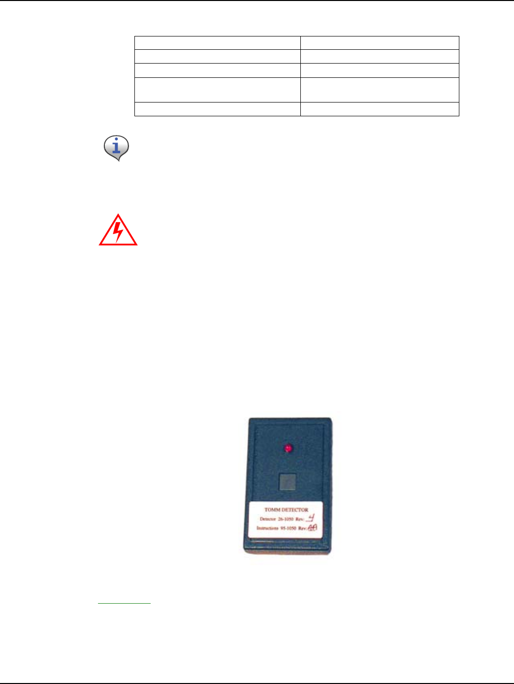
RF Busters
Verify that the RF Buster is working correctly. Press and hold the push button Switch. The LED
lights red, and the internal speaker sounds for approximately 1/2 second. If nothing happens or the
LED lights and speaker sound continuously, then the 9V battery is probably low and needs to be
replaced.
To access the battery compartment, open the spring-loaded cover on the back of the RF Buster. Take
care not to misplace the cover or damage the battery door spring mechanism.
Figure 2 - 1. RF Buster
See Appendix B, Using the RF Buster for detailed instructions on how to use the RF Buster.
taJQM qÜêÉ~Ç=iìÄêáÅ~åí
táêÉ=_êìëÜ `~ÄäÉ=íáÉë
iÉ~â=ÇÉíÉÅíáçå=ëç~é mêÉëëìêÉ=Ö~ìÖÉë
dêÉó=ëéê~ó=é~áåí=~åÇ=é~áåí=Äç~êÇ=Eíç=
éêÉîÉåí=çîÉê=ëéê~óáåÖF
`Éää=éÜçåÉ=çê=OJï~ó=ÅçããìåáÅ~íáçå=
ÇÉîáÅÉ
gìãéÉê=Å~ÄäÉë ^åó=êÉèìáêÉÇ=ëéÉÅá~äíó=íççäë
Your supervisor carries shovels, spades, hack saws, other specialty tools, and
ladders. Take care to check the work area each time you change locations. Be
certain there are no tools left behind.
Do not clean the module or the cover on-site. Static Discharge may result, can
ignite a natural gas leak, and is a risk of fire or explosion.
Table 2-1. Gas Meter Installation and Module Retrofit Tool List
DRAFT
24 Feb 2010
Landis+Gyr Chapter 2 - Preinstallation
Two-Way Gas Endpoint Installation Guide 98-1123 Rev AA 9
Install Material
The Gas Meter Exchange process consists of using predetermined route information that identifies
the meters that need to be retrofitted with the Landis+Gyr Gas Meter Module and methods for
recording data to document the installation. The route information describing the account address,
existing meter ID, estimated meter reads, and any special instructions that describe circumstances
unique to that particular account is supplied at the Cross Dock.
From the Cross Dock, obtain the Meter Modules to be installed. Installers will be issued data that
includes the route, address, meter ID, and estimated read for the particular meters, plus specific
instructions and required field collects information.
Each installer must validate that the route information is correct before leaving the Cross Dock.
Meter Compatibility
This Gas meter Compatibility List is the result of retrofit experience and feedback from American
Meter.
Every attempt has been made to ensure the accuracy of the information in this table. There may be
limitations to compatibility unknown to Landis+Gyr due to changes made which L+G has been
unable to document through our research and substantial meter library. Any questions about the
compatibility information should be forwarded to your L+G representative.
Metal indexes cannot be used and must be replaced. Only indexes with plastic
gears and pointers are supported.
Table 2-2. Gas Meter Compatibility List
jçÇÉä pí~êí=vÉ~ê båÇ=vÉ~ê aêáîÉ
^i=NTR NVRU NVVP NÛ=L=OÛ
^i=ORM NVSS NVUR OÛ
^i=PNM NVTV NVUR OÛ
^i=QOR NVSR `ìêêÉåí OÛ
^q=ORM NVSU `ìêêÉåí NÛ=L=OÛ
^q=PRM NVVU `ìêêÉåí OÛ
^`=NTR NVSR `ìêêÉåí NÛ=L=OÛ
^`=ORM NVTS `ìêêÉåí NÛ=L=OÛ
^`=SPM NVVU `ìêêÉåí OÛ
^j=ORM NVUR `ìêêÉåí NÛ=L=OÛ
DRAFT
24 Feb 2010
Chapter 2 - Preinstallation Landis+Gyr
10 98-1123 Rev AA Two-Way Gas Endpoint Installation Guide
Validated Meter Index Part Numbers
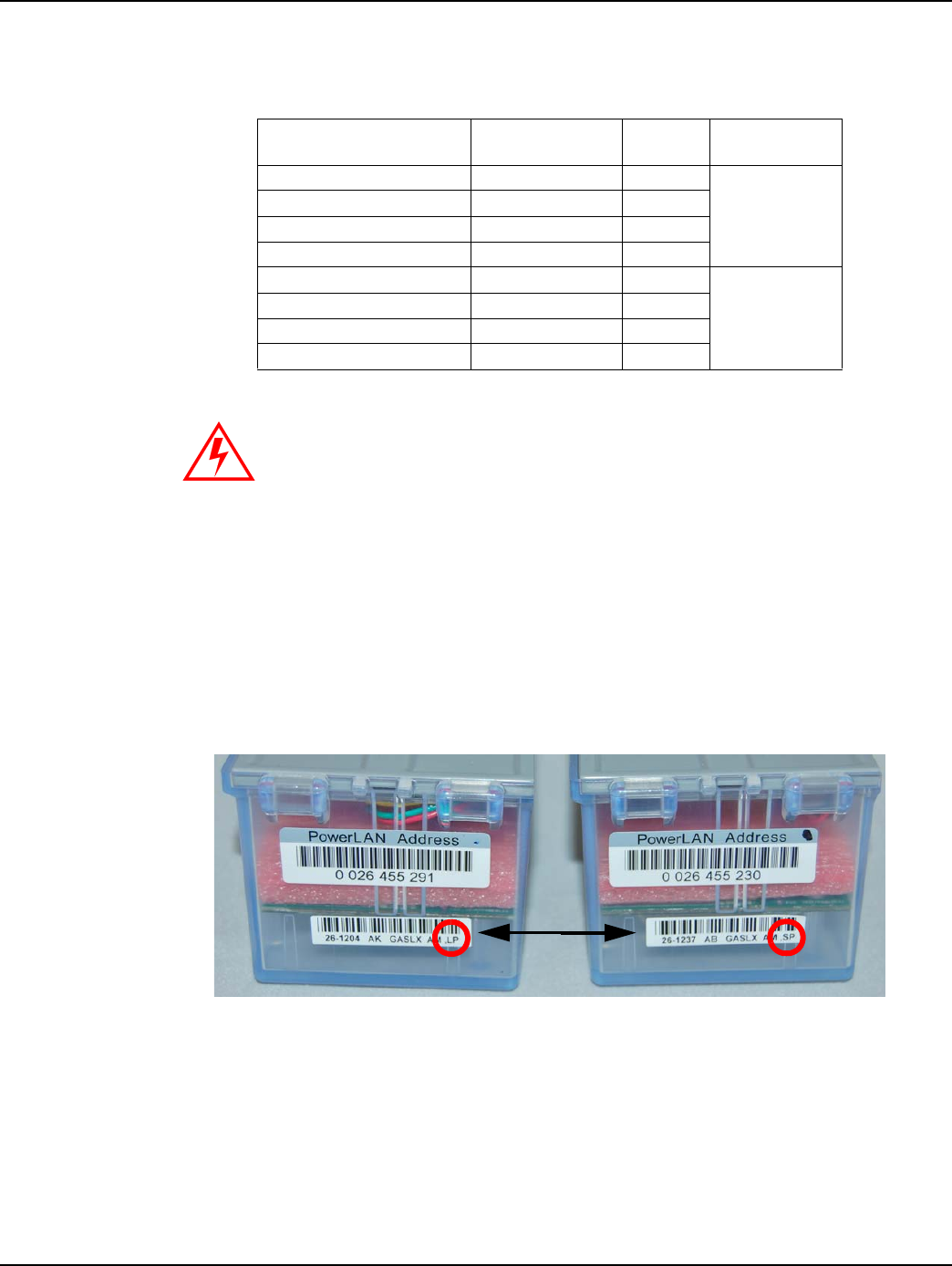
Long and Short Post Gridstream M120 Module Covers
Post lengths differ for Gridstream M120 modules used for pointer- and odometer-type indexes.
There are two part numbers used. The Long Post unit, model # 26-1204, is used for pointer-type
indexes. The Short Post unit, model #26-1237, is used for odometer-type indexes. Beyond post
length, modules can be differentiated in multiple ways. Check the lower bar code label on the side of
the module cover. The model number is listed at the beginning of the label, and the last two
characters that appear will be either “LP” or “SP” to indicate the model unit.
Figure 2 - 2. Long and Short Post Module Cover labels
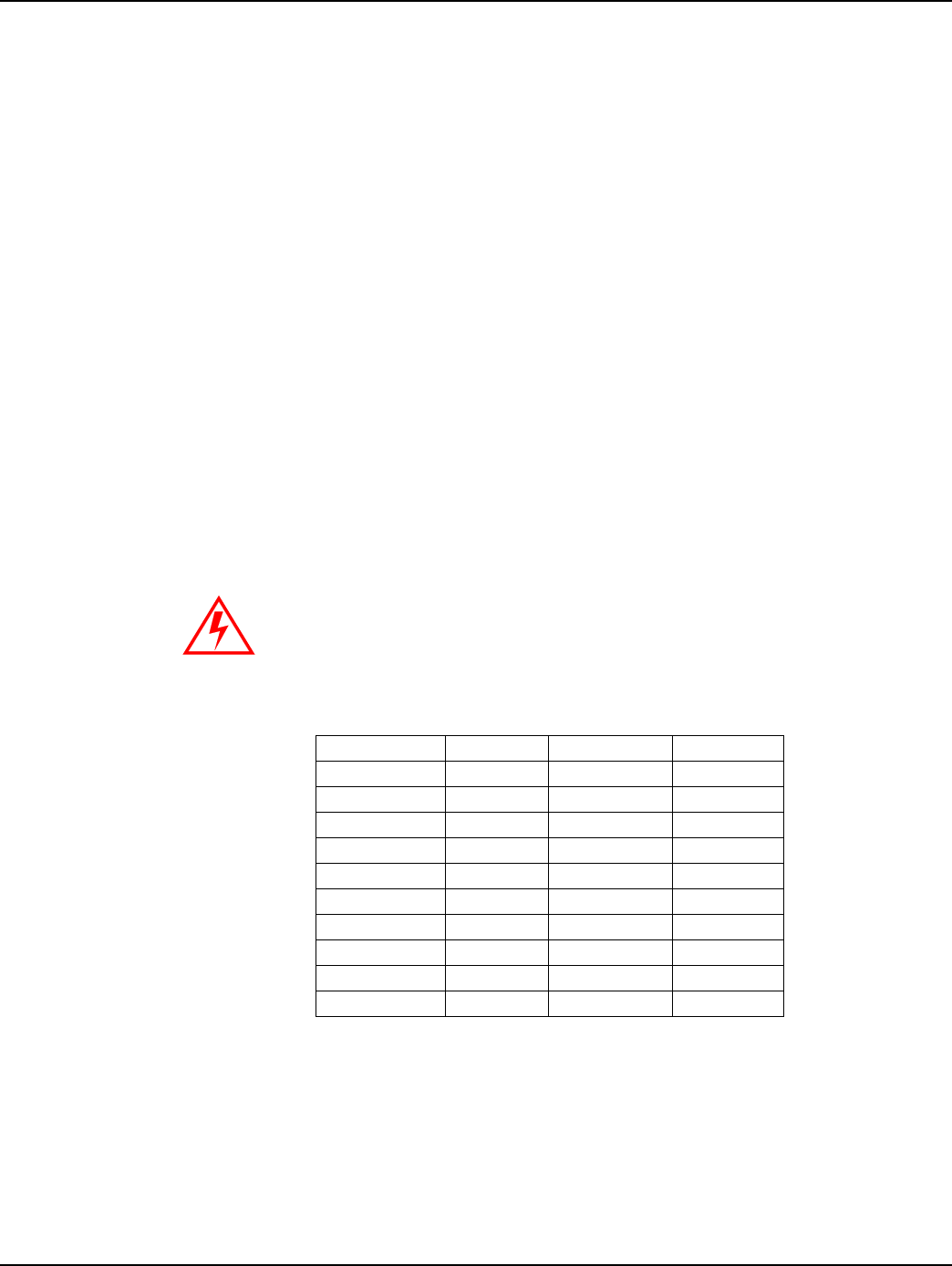
Table 2-3. Indexes and Part Numbers (SC= Speed Counter, TC= Temperature Compensated)
fåÇÉñ=qóéÉ ^ãÉêáÅ~å=m~êí=kçK aá~ä=çê=“_Ò=
åìãÄÉê
rëÉ=dêáÇëíêÉ~ã=
jNOM=jçÇÉä=@
N=cíK=mçáåíÉê=ïL=p` OURPUdNMM _NTO OSJNOMQ
N=cíK=mçáåíÉê=ïL=p`=C=q` OURPUdNMO _NTQ
O=cíK=mçáåíÉê MQVTOdMTO _QOQ
O=cíK=mçáåíÉê=ïL=p`=C=q` MQVTOdMPV _NTT
N=cíK=lÇçãÉíÉê RQUUTdMMR _SVTJt OSJNOPT
N=cíK=lÇçãÉíÉê=ïL=q` RQUURdMMS _TMSJt
O=cíK=lÇçãÉíÉê RQUURdMMS _SVUJt
O=cíK=lÇçãÉíÉê RQUURdMNR _UMUJt
No warranty is expressed or implied regarding the use of similar but un-
validated indexes.
POINTER ODOMETER
DRAFT
24 Feb 2010
Landis+Gyr Chapter 2 - Preinstallation
Two-Way Gas Endpoint Installation Guide 98-1123 Rev AA 11
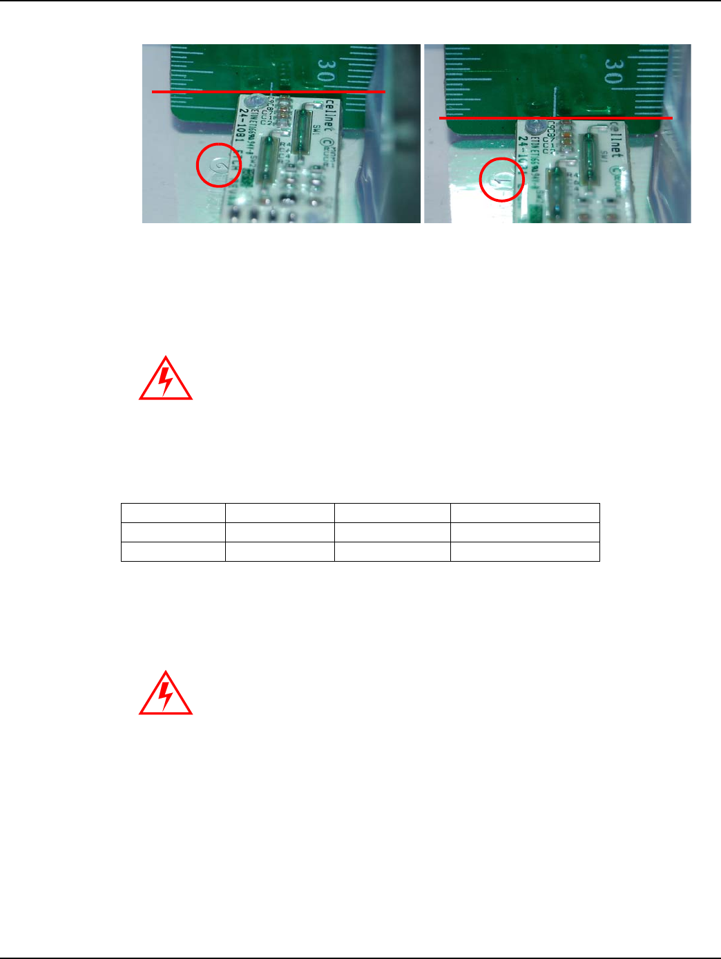
Figure 2 - 3. Long and Short Post Module Cover internal differences
The post length difference in the two models is only about a quarter-inch, but this critical installation
parameter ensures accuracy and functionality. Note also the “1” and “2” cast into the cover next to
the sensor board, with “2” designating pointer index usage and “1” being for the odometer index.
Meter Hardware
Compliance
This apparatus is suitable for Class I, Division 1, Group D Hazardous Locations.
Safety and Environment
Prerequisite Training
Installers should be instructed in the following safety elements as well as any site-specific safety
issues:
• Hazard Communication (Employee Right to Know)
• Lifting
Installing the 26-1204 on a meter with an odometer index may cause the
sensor to break.
Installing the 26-1237 on a meter with a pointer index may cause the
endpoint to count incorrectly.
POINTER ODOMETER
Table 2-4. Meter Index and Module Hardware
rëÉ aáãÉåëáçåë pÅêÉï=qóéÉ m~êí=kçK
fåÇÉñ NMJPO=ñ=NLQ pp=oçìåÇ=eÉ~Ç `ÉääåÉíW======OOJMMQM
jçÇìäÉ NLQJOM=ñ=RLU pp=cáääáëíÉê=eÉ~Ç ^ãÉêáÅ~åW==QPPVPmMVV
Warning - Explosion Hazard - Substitution of components may impair
suitability for Class I, Division 1.
DRAFT
24 Feb 2010

Chapter 2 - Preinstallation Landis+Gyr
12 98-1123 Rev AA Two-Way Gas Endpoint Installation Guide
• Safe driving
• Use of hand tools
• Confined space
Preliminary Checks
The installer should already be able to operate the Handheld computer. Additionally, you should
already have route information and the required number of endpoints.
• Verify that you are at the correct site, specified on the handheld computer or work order.
• Verify that the site is safe for you and your equipment.
• Notify the customer of your presence. Tell the customer that you must have access to the meter.
If necessary, have the customer sign the work order.
• When installing meters, follow any guidelines issued by your company in addition to those
given in this guide.
• Never perform an installation during a lightning storm or under excessively wet conditions.
Site Requirements
The site must comply with the following criteria:
• There is no chance that another object will be set over the antenna.
• Some instances may require additional cable.
• Maximum cable length is always 200 feet.
FCC Information to the User
Manufacturer: Cellnet
Model Name: Gridstream M120
FCC ID: R7PER6R1S1
This device complies with Part 15 of the FCC rules. Operation is subject to the following two
conditions:
1Thisdevicemaynotcauseharmfulinterference,and
2Thisdevicemustacceptanyinterferencereceived,includinginterferencethatmaycause
undesiredoperation.
FCC Class B
This equipment has been tested and found to comply with the limits for a Class B digital device,
pursuant to Part 15 of the FCC Rules. These limits are designed to provide reasonable protection
against harmful interference in a residential installation. This equipment generates, uses, and can
radiate radio frequency energy and, if not installed and used in accordance with the Instructions, may
cause harmful interference to radio communications. However, there is no guarantee that
interference will not occur in a particular installation. If this equipment does cause harmful
interference to radio or television reception, which can be determined by turning the equipment off
DRAFT
24 Feb 2010

Landis+Gyr Chapter 2 - Preinstallation
Two-Way Gas Endpoint Installation Guide 98-1123 Rev AA 13
and on, the user is encouraged to try to correct the interference by one or more of the following
measures:
• Reorient or relocate the receiving antenna.
• Increase the separation between the equipment and receiver.
• Consult L+G or an experienced radio technician for help.
RF Exposure
In accordance with FCC requirements of human exposure to radio frequency fields, the radiating
element shall be installed such that a minimum separation distance of 20 centimeters will be
maintained.
Changes or modifications to this device not expressly approved by Cellnet
Technology, Inc. could void the user's authority to operate the equipment.
DRAFT
24 Feb 2010
DRAFT
24 Feb 2010

3
Two-Way Gas Endpoint Installation Guide 98-1123 Rev AA 15
On-Site Preparation
Arrival at Install Site
1Uponarrivingattheinstallationsite,verifytheaddressintheHandheld.ChecktheHandheld
forspecialinstructionsforthatsite(forexample,medicalcustomer,dog,keyrequiredforaccess
tometer,meterlocation,andsoon).IfamedicalalertcodeappearsintheHandheldforthat
address,theyaretoskiptheinstall,enteranappropriateskipcode,andmovetothenext
exchange.Amedicalalerttagmaybelocatedontheelectricmeter.
2IftheinstallercomesacrossameterwhereamedicalalertcodeappearsintheHandheldforthat
address,theyaretodiscontinuetheexchange,entertheappropriateskipcode,andmovetothe
nextexchange.
3VerifythatthemeterIDofthemeterattheaddressisthesameasthatintheHandheldrecord;if
not,verifyitasecondtime.IfthemeterIDdoesnotmatch,recordtheinformation,including
mismatchedIDonhardcopy,recordskipcodeofmeterIDmismatch,andcallyourSupervisor
fordirection.
4Verifythatthesealsareintactandpresent.Ifthemeterisunsealedandthereisnoevidenceof
tampering,completethemeterexchangeormoduleretrofit.Ifthereissuspectedtamperingor
evidenceofdiversion,donotcompletetheinstall.Recordthediversiononhardcopy,enterthe
skipcodeofdiversioninHandheld,andcallyoursupervisorimmediately.
5Ifthepremiseisvacantandtheserviceisshutoffattheserviceriservalve,completethemeter
exchangeifatallpossible.Ifyouareunabletogainaccesstothepremise,finishyourrouteand
thentryagainbeforereturningtotheCrossDock.EnterappropriatecodeinHandheld.
6Inspectthemeterforanygasleaks,unsafeconditions,excessiverusting,ordamage.While
performingthistechnicalreview,inspectthemeterforpoorconditionssuchasexcessrust,
tampering,orodorofgas.Ifyoujudgethemeterisseriouslydamaged,reportit,enterthe
appropriatecodeintheHandheld,andcallyoursupervisorfordirections.
7Ifitisdeterminedthatthemeterhasnounsafeconditions,youarereadytoproceedwiththe
moduleretrofit.DatawillberequiredtobeenteredintotheHandheld.Ifthereadingisoutof
range(indicatedbyapromptontheHandheld),thenretypethemeteridentificationnumberʹs
lastfourdigitstore‐verifythecorrectmeter.Reenterthegasmeterindexreadintothe
Handheld.
SeeʺToBeginMeterModuleRetrofitʺonpage 43forinformationaboutmoduleexchange
instructions.
8Ifthemeteristobeexchangedanditispartiallyburied,enteraskipcodeof“buried”andmove
tothenextaccount.Ifatiltedmeteristobeexchanged,performtheexchangeandcorrectthe
tilt.Ifamoduleistobeinstalledonatiltedmeter,completetheinstall,andenteraskipcodeof
“tilted.”
9Iftheinstallerismetbyaviolentorthreateningcustomer,immediatelyleavethepremiseand
callyourSupervisor.Ifnecessary,dial911,afterwhichyouwillenterintotheHandheldandon
thehardcopyaskipcodeof“violencecode.”
DRAFT
24 Feb 2010
DRAFT
24 Feb 2010

4
Two-Way Gas Endpoint Installation Guide 98-1123 Rev AA 17
Gas Meter Exchange
Meter Exchange Process
Arriving at the Location
1Theinstallerconfirmsthattheyareattherightrouteaddressforthatappointmentusingthe
Handheld.Theinstallerarrivesatthelocationon‐timeandwithallthetoolsandequipment
necessarytocompletetheinstallationwithouthavingtoreturntothesupportvehicle.If
applicable,locatetheoutsideshutoffvalveincaseoftroubleoremergency.
2Whenthecustomeranswersthedoor,introduceyourselfandstatethereasonforyourvisit.
–verifythatthecustomerisatleasteighteenyearsofage.
– Showthecustomeryouridentification.
3 Confirmthenatureoftheappointmentandthetimecommitmentrequiredfromthecustomer.
Makesurethecustomerknowsandagreesthatitisconvenientforyoutoturnoffthegasduring
theinstallationprocess.
Verifying the Meter Site
Locate the meter and confirm the existing meter number, type, and size.
–Ifthemeternumberiscorrectbuttypeandsizedonotmatchtheequipmentthatyouhave
beenissued,callyourSupervisorandrequesttheappropriateequipment.
–IfthemeterIDdoesnotmatchtheinformationinthehandheld,callyourSupervisorfor
meternumberverification.
–Ifallinformationiscorrect,continuetheinstallationprocess.
–Priortoproceedingwiththemeterexchangeprocess,inspecttheconditionofthegas
regulator.Iftheregulatorisdefective,itmustbereplaced.Followtheutility‐specific
guidelinesforregulatorexchange.
DRAFT
24 Feb 2010

Chapter 4- Gas Meter Exchange Landis+Gyr
18 98-1123 Rev AA Two-Way Gas Endpoint Installation Guide
Confirming Proper Installation Conditions
1Fortheinstallationtoqualify,confirmALLofthefollowingpre‐existingconditions:
–Visuallyexaminetheshut‐offthatitdoesNOTshowsignsofleakingordisrepair.
–PerformthesnifftestforsignsofgasleaksusingtheNaturalGasDetectionDevice,andthen
thesoaptestontheshutoffandcouplings.
–N
oDiversionorTamperingEvident‐Visuallyinspecttheservicetothemeterforsignsof
diversionortampering.
– AppropriateAccess‐Confirmthataccesstothemeterallowsaminimumacceptablework
areatobeestablished.Minimumworkareaincludeswrenchclearance,accesstoshut‐off.
– AppropriateService&PipingCondition‐Visuallyinspecttheageandconditionofthe
serviceandpiping.Confirmthatserviceandpipingarefitfortheremovalandinstallation
ofanewmeterandthattherearenopre‐existingleaks.
– AppropriateMeterOrientation‐Confirmthatthemeterisinstalledhorizontallyorsuch
thatthemeterexchangecannottakeplace.
–IfanyimproperconditionsarefoundcontactyourSupervisorimmediately.TheSupervisor
willconfirmyourassessmentandgiveyoudirectionforeithercompletingtheinstallationor
issuingaskipcodeintheHandheld.
2Setuptheareaforinstallation.Forinsidesets,turnonallavailablelighting.Clearan
appropriateworkspaceandlayoutalltools,andequipment.Prepareforleaksoremergency
shut‐off.
Shutting Off the Service
1Notifythecustomerthatgasservicewillbeinterruptedandreconfirmthatallgasapparatuses
areoff.Inspecteachgasapplianceforproperoperation.Inspectthemetersetforcorrosion,
burialoroverbuilding,damage,improperinstallation,misalignment,outdatedregulator
(Model1213Bor043R),orthesmellofnaturalgas.
2 Connectthebondingjumperfromservicerisertothepremiseline.Verifythattheexistingmeter
isoffbyisolating(shutoff)allgasapparatusesandconfirmthatthereisnoflowonthemeter
andregister.Ifthemeterisnotfunctioningcorrectly,contacttheSupervisorimmediately.The
Supervisorwillconfirmyourassessmentandgiveyoudirection.
3Manuallyclosethecustomerʹsshutoffvalve.
–Ifyouhaveanyproblemclosingthevalve,contactyourSupervisorfordirectionwhichmay
include,ifapplicable,usingtheoutsidecurbstopforshut‐off.
–Iftheoutsidecurbstopisactivated,yourSupervisorwillnotifytheUtilitySupervisor.
4Removetheoriginalmeter.
aUsingapipewrenchandbackup,attempttoloosenthemetercouplingnuts.
bUsemildtorquebuildingtomoderatesteadytorqueuntilthecouplingnutbeginstoturn.
cDonotjerkorsnapthewrenches.Damagecouldoccur.
d Loosenbothcouplingnutsandremovetheoldmeterfromthemeterset.Ifyouhaveany
problemlooseningthecouplingnuts,contactyoursupervisorfordirection.
eWhenapplicable,removealloldgasketmaterialinthecouplingnuts.Inspecttheregulator
andexchangetheregulatorifitisdamagedordefective.
DRAFT
24 Feb 2010

Landis+Gyr Chapter 4 - Gas Meter Exchange
Two-Way Gas Endpoint Installation Guide 98-1123 Rev AA 19
Installing the New Meter
1Removethenewmetertagfromthenewmeter.
2Writeinstalldate,address,andinitialsonnewmetertag.
3Placenewmetertagontheoldmeterregister.
4Insertnewgasketswhereapplicable.
5 Exchangetheregulatorifitisdamagedoroutdated.Exchangeanydamagedinsulatingunions.
Levelthemetersetifthesetistilted.
6Tightentheinlet‐couplingnut.
7Installpressuregaugetometeroutlet,slowlyopentherisevalve,andadjustregulatorto
appropriategaspressureatthemeteroutlet.
aClosetheriservalveandremovethepressuregauge.
bVerifymeteroperation.
c Reconnecttheoutletpiping.
8Beforere‐servicing‐ifservicewasshutoffpriortothemeterexchange,donotrestoreservice.
Restoring Service, Purging the Air, and Performing the Leak Test
1Opentheshut‐offvalveveryslowly.
–Ifyouhaveanyproblemopeningthevalve,contactyourSupervisorfordirection.
2Checkthetestdialformovementtomakecertainnoleaksoccurredwhileperformingthe
installation.
aSealtheregulator.
b Disconnectthebondingjumper.
cCleanandpaintthemeterset.
3Checkthecouplingnuts,serviceandpipingforleaks.Perform“leaktest”(snifftestforsignsof
gasleaksusingtheNaturalGasDetectionDeviceandthesoaptest)andre‐tightenifnecessary.
4 Reenterthepropertyandpurgetheairfromthegaslinebybleedingthefurthestgasapparatus
fromthemeter.Youmustbleedeachindividualapparatus.
Relighting All Apparatuses and Confirming Their Operation
Follow the procedure provided to you by the Utility for appliance relighting. If any adverse
conditions arise, immediately shut off the gas, contact your supervisor for instructions, and record
the appropriate comment in the Handheld such as, red/yellow tag defective appliance situation. Enter
a Skip code such as, “red/yellow tag” in the Handheld.
Do not clean the module or the cover on-site. Static discharge can ignite a
natural gas leak and is a risk of fire or explosion.
During the installation, replace all biscuits in the outlet piping, and leave meter
off “as found”.
DRAFT
24 Feb 2010

Chapter 4- Gas Meter Exchange Landis+Gyr
20 98-1123 Rev AA Two-Way Gas Endpoint Installation Guide
Programming the Module
Refer to Chapter 3, Using the Handheld Device.
Performing Data Collection
1SeeChapter 3,UsingtheHandheldDevice.
2Sealthenewmeter.
Cleaning Up the Work Area
Clean up all installation tools, equipment and debris. Turn off any lights that you may have turned
on. Restore the customer premise to the pre-visit condition.
Exiting the Premise
1Doafinalchecktoensurethatyouhaveallofyourequipmentandtools.
2 Thankthecustomerforallowingustoservicetheirgasmeter,exitthepremise,andprovidethe
customerwithadoorhanger.
Module Retrofit (Index or Register) Replacement
Refer to Chapter 5, Meter Module Retrofit.
Customer Skip or Cancellation
If the customer's existing conditions do not qualify for new meter installation, notify your
Supervisor. Wait at the site until your Supervisor arrives for further instructions. If, in the
Supervisor's opinion, the condition of the customer's existing service piping or appliances is such
that significant damage would result from attempting to remove and replace the existing gas meter,
your Supervisor will so inform the Utility of the condition. The Supervisor will advise you to:
• Inform the customer as to why the change-out will not take place.
• Document the situation in your handheld.
• Continue on to your next appointment.
If There Is Damage On Site When You Arrive
• Call your Supervisor immediately. Communicate the urgency of the situation. Your Supervisor
will immediately initiate any necessary actions.
• Do not leave the customer site until directed to do so.
• It may be necessary to dial 911.
IMMEDIATELY turn off the gas. This will eliminate or minimize any property
damage to customer.
DRAFT
24 Feb 2010

Landis+Gyr Chapter 4 - Gas Meter Exchange
Two-Way Gas Endpoint Installation Guide 98-1123 Rev AA 21
Battery Change Out
When the NOC analyst notices that the battery flag (R) is set, it could be due to:
• a single end-point occurrence, where the end-point may require more current to operate. In this
case, a single battery needs to be replaced
• occurrence on several end-points, where a battery change out program needs to be implemented
within the following year
• the flag being set during the coldest part of the day, where the battery may have less than 20% of
energy left (2-4 years of service time)
• occurrence more often even during the daylight hours. In this case, the battery has even less
energy remaining (1-2 years of service time)
To Change Out The Battery
1Swipeamagnetonthelefthandsideofthemainboardcompartment
2ListenforuptotenbeepsontheRFbuster(whichensuresthatthelatestdataissavedtonon‐
volatilememory)
3Removethefourmetercovermountingscrews
4RemovetheGridstreamM120modulefromthegasmeter
5Openthebatterycompartmentdoor
6R
eplacethebatteryassemblywithanewone(batterymodel#40‐1590H)
7Closethebatterydoor
8Replacethemoduleontothegasmeterusingthefouroriginalmountingscrews
9Inserttwonewsecuritysealsintothehousing.
. .
If the gasket is old and no longer provides a good meter to module seal, replace
the meter gasket with a new one.
If the module has already gone stale, perform the above steps, with the
exception that when the battery door is open, connect the USB programming
cable to the Gridstream M120 module. Use the HH to re-enter the energy value
from the mechanical index dials and re-program the module.
Once the above steps are completed, it will require at least three hours for all
flags to be cleared (based on five transmissions per hour and Alarm Count =
10).
DRAFT
24 Feb 2010
DRAFT
24 Feb 2010
5
Two-Way Gas Endpoint Installation Guide 98-1123 Rev AA 23
Meter Module Retrofit
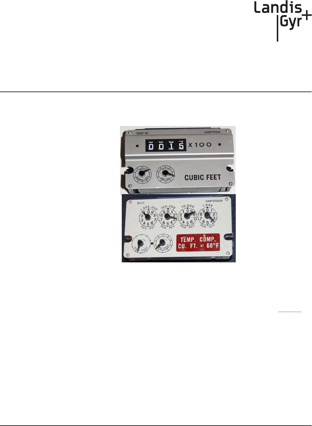
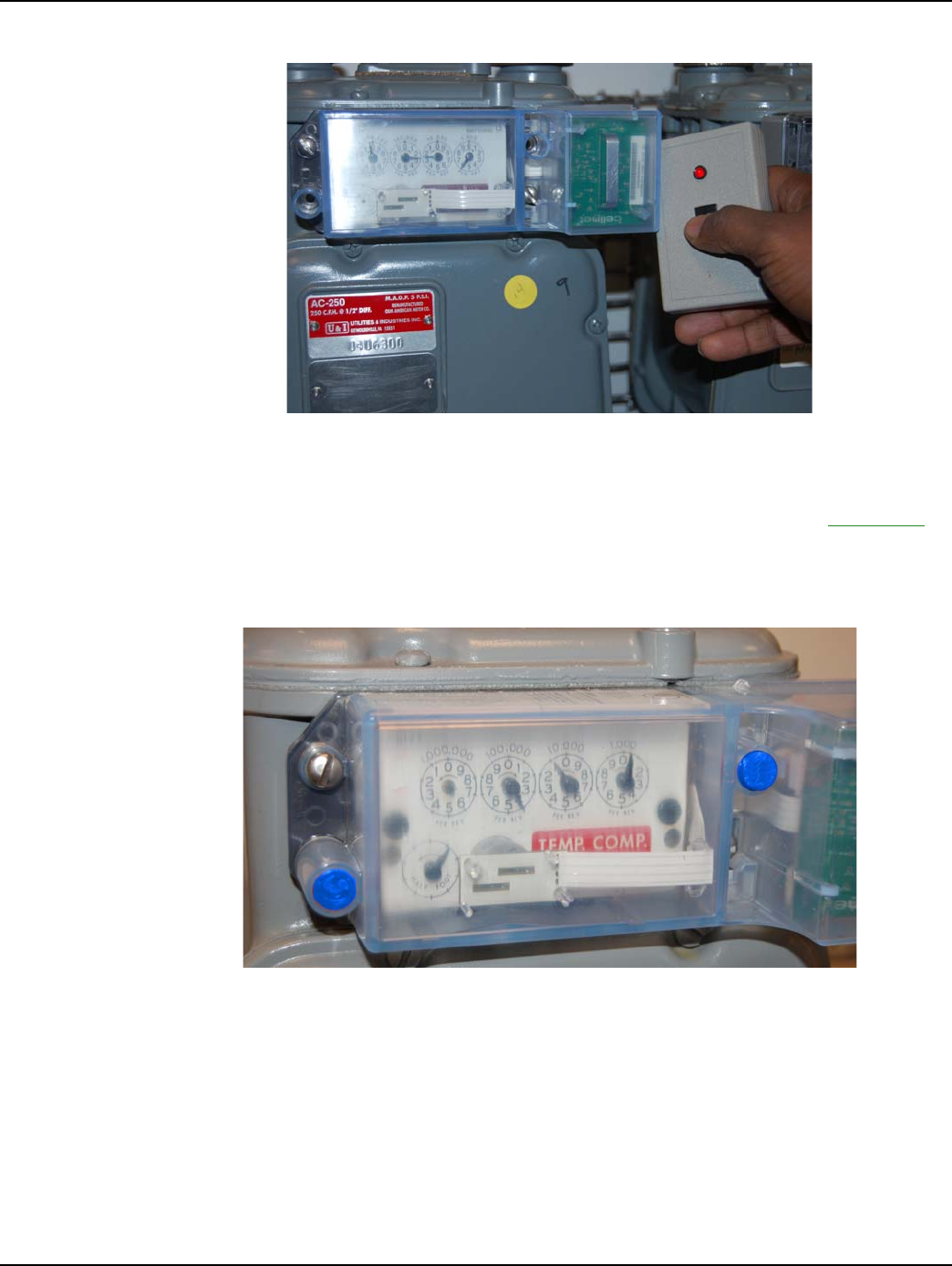
This chapter outlines the procedure for Meter Module installation. Examples of two supported index
types appear in the following illustration.
Figure 5 - 1. Two Examples of Supported Index Types
To Begin Meter Module Retrofit
Prior to beginning the meter module retrofit, make sure you have followed the steps on Page -15.
1Removethetampersealsandindexcoverfromtheoriginalgasmeter.
DRAFT
24 Feb 2010
Chapter 5 - Meter Module Retrofit
24 98-1123 Rev AA Two-Way Gas Endpoint Installation Guide
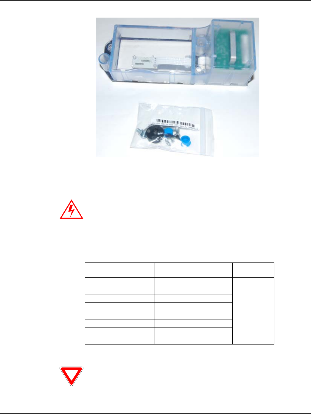
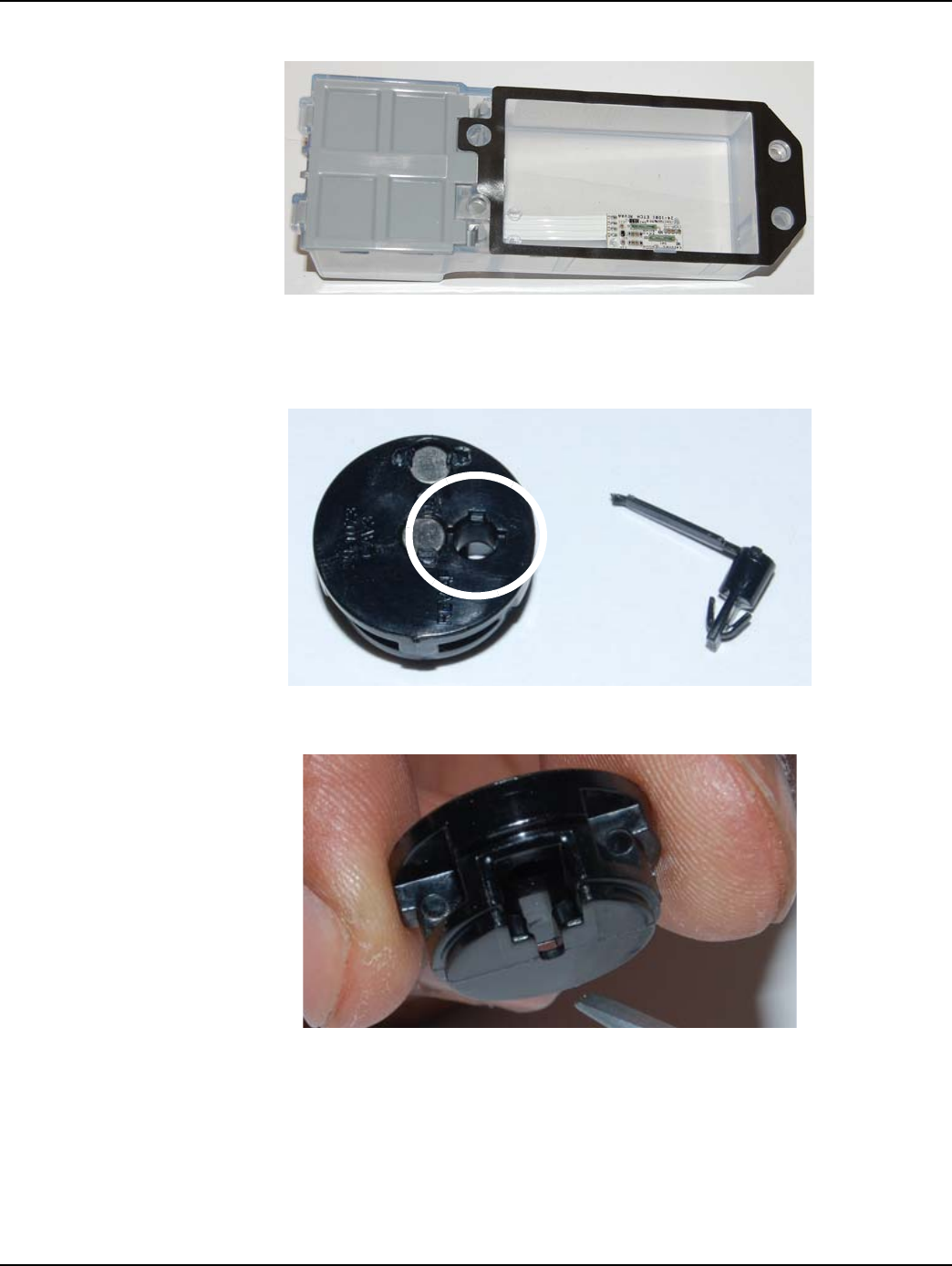
Figure 5 - 2. Meter Module kit before installation
2Removealloftheoriginalgasketmaterial.Replacetheindexifitisdamaged,ifthegearsare
discolored,orifitismetal.
Validated Meter Index Part Numbers
Metal indexes cannot be used and must be replaced. Indexes must use
ALL plastic gears and pointers and be housed in a plastic case.
Table 5-1. Indexes and Part Numbers (SC= Speed Counter, TC= Temperature Compensated
fåÇÉñ=qóéÉ ^ãÉêáÅ~å=m~êí=kçK aá~ä=çê=“_Ò=
åìãÄÉê
rëÉ=dêáÇëíêÉ~ã=
jNOM=jçÇÉä=@
N=cíK=mçáåíÉê=ïL=p` OURPUdNMM _NTO OSJNOMQ
N=cíK=mçáåíÉê=ïL=p`=C=q` OURPUdNMO _NTQ
O=cíK=mçáåíÉê MQVTOdMTO _QOQ
O=cíK=mçáåíÉê=ïL=p`=C=q` MQVTOdMPV _NTT
N=cíK=lÇçãÉíÉê RQUUTdMMR _SVTJt OSJNOPT
N=cíK=lÇçãÉíÉê=ïL=q` RQUURdMMS _TMSJt
O=cíK=lÇçãÉíÉê RQUURdMMS _SVUJt
O=cíK=lÇçãÉíÉê RQUURdMNR _UMUJt
No warranty is expressed or implied regarding the use of similar but un-
validated indexes.
DRAFT
24 Feb 2010
Landis+Gyr Chapter 5 - Meter Module Retrofit
Two-Way Gas Endpoint Installation Guide 98-1123 Rev AA 25
WHENREPLACINGANINDEX,YOUMUSTENTERTHEMETERREADINTOTHE
HANDHELDANDNOTE“INDEXEXCHANGED”INTHECOMMENTSECTION.ForIndex
visualverificationandexchange,seeAppendix A,SupplementalInformationAboutIndexes.
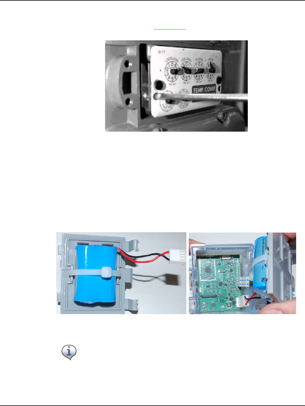
Figure 5 - 3. Removing the Index (one screw on each side)
3Cleantheareabehindtheindexandcovergasketsurfaceonthemeterwithawirebrushanda
gasketscraper.
4Verifythatthemeterdialareaisfreeofanydebristhatmayhampermoduleinstallation.
5Removethebatterydoor.
6 Configurethemodule.
7 Positionthemoduledoorsothatthebatteryconnectorisnearthejackandconnectthebattery.
8Manuverthedoorintoposition,guidethetabsintothereceivers,andsnapthebatterydooronto
themetermodule.
Figure 5 - 4. Connecting the battery pack
6InstalltheMeterModuletothemeterbyscrewinginthefouroriginalmountingscrews.
Tightenthescrewsuntilthecoversitssnug,thentightenanadditionalquarter‐turn.
This module is powered by a model 40-1235 battery pack. Battery pack
appearance may vary.
DRAFT
24 Feb 2010
Chapter 5 - Meter Module Retrofit
26 98-1123 Rev AA Two-Way Gas Endpoint Installation Guide
Figure 5 - 5. Battery Compartment closed
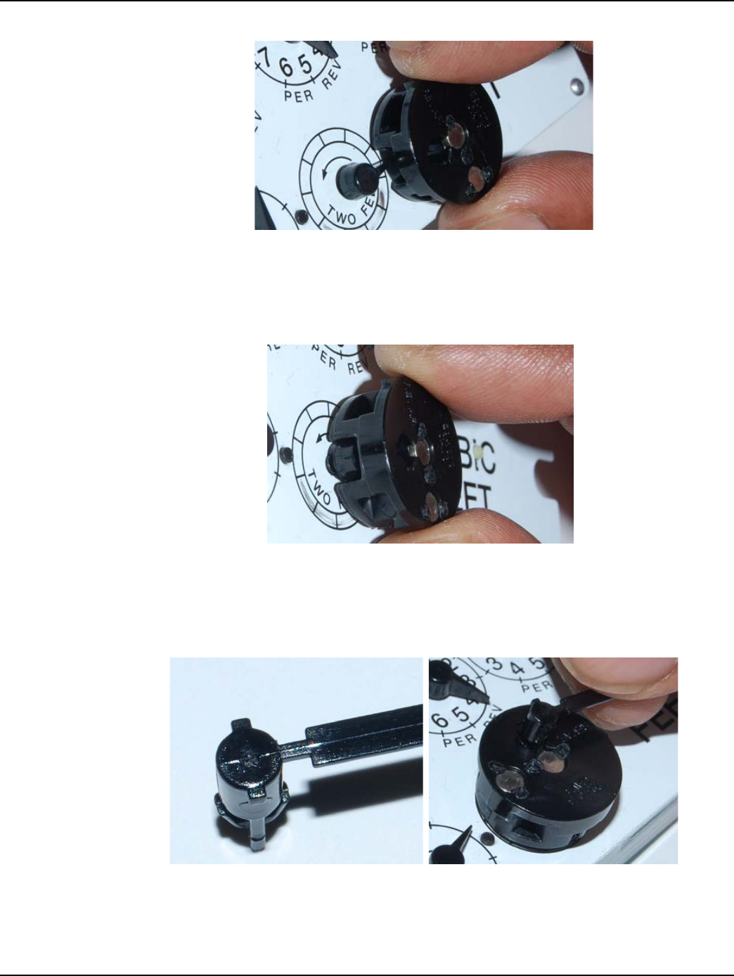
After the battery is installed, prepare to install the Dial Wheel.
Figure 5 - 6. Dial Wheel Kit (note Dial Wheel Pin Tab Hole indentations) separated
Figure 5 - 7. Dial Wheel Pointer Slot
7WhileholdingtheDialWheel,notethelocationofthePointerSlot.Withtheindexsittingona
worksurface,settheDialWheelontheindexfacewiththepointerslotorientedtowardsthe
pointer.
DRAFT
24 Feb 2010
Landis+Gyr Chapter 5 - Meter Module Retrofit
Two-Way Gas Endpoint Installation Guide 98-1123 Rev AA 27
Figure 5 - 8. Dial Wheel with pointer slot positioned for pointer entrance
8SlidetheDialWheeltowardthepointeruntiltheDialWheelcentercontactsthepointer.The
pointercenterwillgentlyimpedetheDialWheel.DonotforcetheDialWheelonthepointer
center.
Figure 5 - 9. Dial Wheel placed on pointer
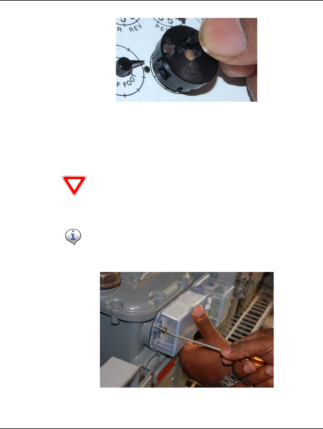
9TaketheDialWheelPinandinsertthepinintotheDialWheelhole.Notethepositionofthe
threetabsoftheDialWheelpin.UsetheplasticconnectingstriptoorienttheDialWheelpinto
fitintothecorrespondingslotoftheDialWheelPinhole.
Figure 5 - 10. Orienting the Dial Wheel Pin before installation
10 Youwillfeelagentleclickasthepinseatsintoplace.Snapofforcutawaytheplasticconnecting
strip.
DRAFT
24 Feb 2010
Chapter 5 - Meter Module Retrofit
28 98-1123 Rev AA Two-Way Gas Endpoint Installation Guide
Figure 5 - 11. Installing the Dial Wheel Pin
After both screws are tightened and the Meter Index is installed, position the Gridstream M120
module for installation. Install, but do not tighten to mounting torque, the first of the module
mounting screws.
Figure 5 - 12. Installing the first Gridstream M120 Module cover mounting screw
Discard the foam spacer in the Gridstream M120 index cover compartment
before mounting the index cover onto the meter.
Use a torque screwdriver set at 10 inch-pounds to install the screws for all
module installations.
DRAFT
24 Feb 2010
Landis+Gyr Chapter 5 - Meter Module Retrofit
Two-Way Gas Endpoint Installation Guide 98-1123 Rev AA 29
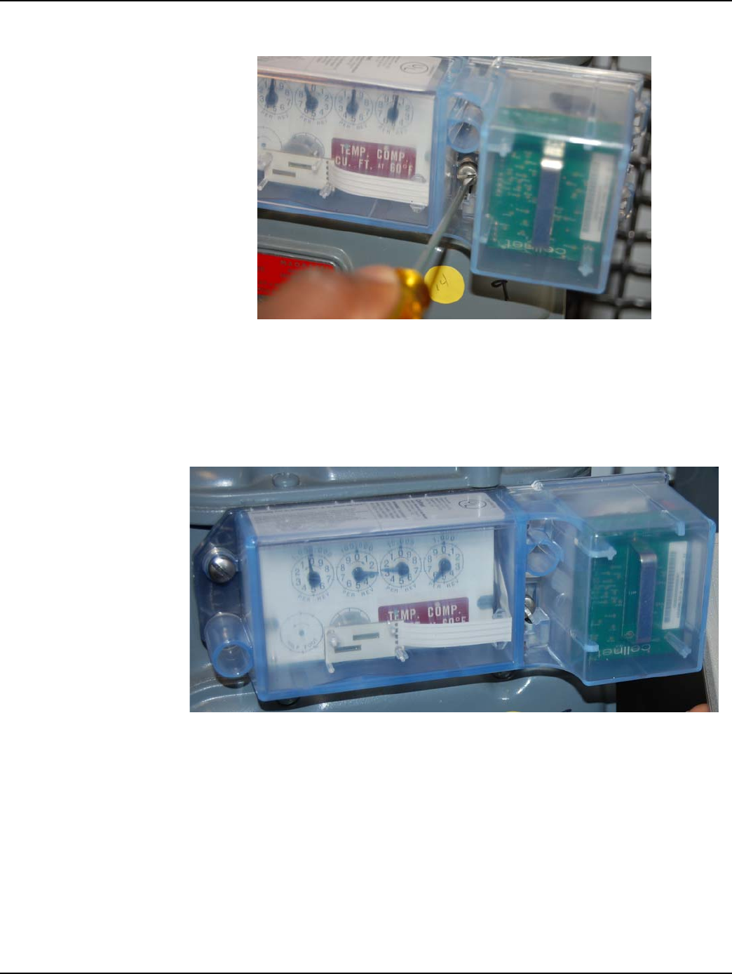
Figure 5 - 13. A screw-holding screwdriver will simplify installing this mounting screw
11 Installtheremainingscrews.Ifavailable,useascrew‐holdingscrewdrivertoinstall
thelowerright‐sidemodulemountingscrewwillsimplifythisaction.Tightenthe
screwsuntilthecoversitssnug,thentightenthescrewsanadditionalquarterturn.
Preparetoverifythatthemoduleistransmitting.
.
Figure 5 - 14. Index and Gridstream M120 Index Cover
DRAFT
24 Feb 2010
Chapter 5 - Meter Module Retrofit
30 98-1123 Rev AA Two-Way Gas Endpoint Installation Guide
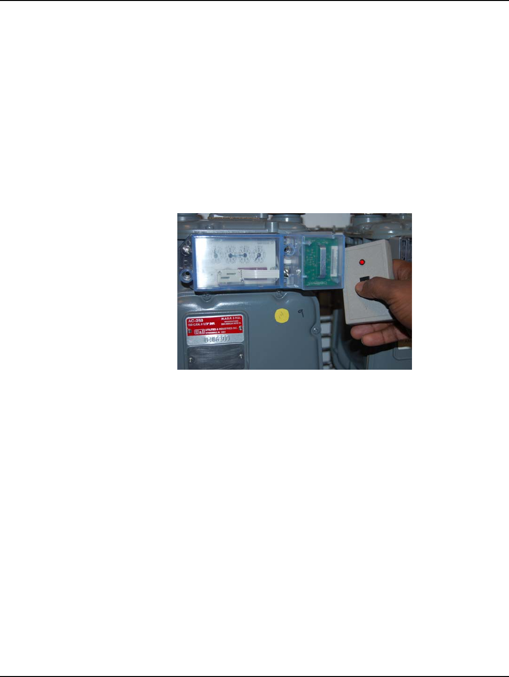
Figure 5 - 15. RF Buster oriented to Meter Module for testing
12 UsetheRFBustertoverifythatthemoduleistransmittingbyholdingtheRFBusterwiththe
magnetsidetothetopupperrightquadrantofthemoduleplastichousing.TheRFBuster
shouldbeeptentimes,indicatingthatthetransmitterissendingRFpackets.SeeAppendix B,
UsingtheRFBusterformoreinformation.
13 Installnewtampersealsovertwodiagonalscrews(upperrightandlowerleft).
Figure 5 - 16. Meter module with security seals installed
14 Cleanupdebrisfromtheretrofitandinstallationprocesses.Entertheappropriateinformation
onadoorhangertag.Adoorhangertagmustalwaysbeleftafterameterisservicedor
exchanged.
15 Attheendoftheday,theinstallerreturnstotheCrossDockforthecheck‐inprocess.The
installershouldalsoturnininventoryofunused,defective,orbrokengasMeterModules.The
installerisresponsibleforreconcilinganydiscrepanciesinchangeddatabeforethecheck‐in
processcanbecompleted.Metermoduleswillnotbecheckedouttoaninstallerwhohasnot
completedthepreviousdayʹscheck‐inprocess.
DRAFT
24 Feb 2010

Landis+Gyr Chapter 5 - Meter Module Retrofit
Two-Way Gas Endpoint Installation Guide 98-1123 Rev AA 31
Do not clean the module or the cover on-site. Static discharge can ignite a
natural gas leak and is a risk of fire or explosion.
DRAFT
24 Feb 2010
DRAFT
24 Feb 2010

Landis+Gyr Chapter 5 - Meter Module Retrofit
Two-Way Gas Endpoint Installation Guide 98-1123 Rev AA 33
DRAFT
24 Feb 2010

Chapter 5 - Meter Module Retrofit
34 98-1123 Rev AA Two-Way Gas Endpoint Installation Guide
DRAFT
24 Feb 2010
A
Two-Way Gas Endpoint Installation Guide 98-1123 Rev AA 35
Supplemental Information
About Indexes
Index Type
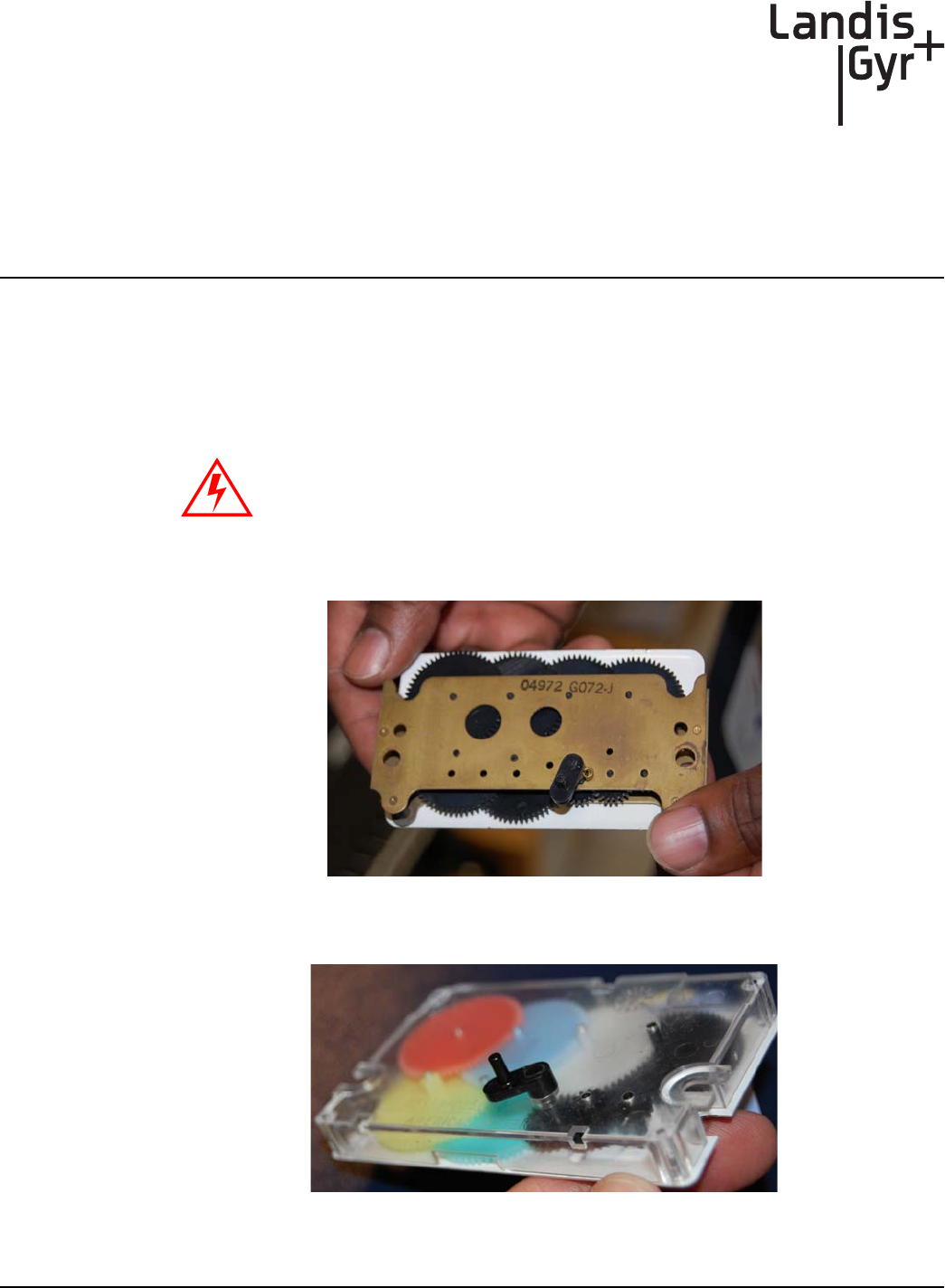
Metal indexes cannot be used with the Gridstream M120 system. If the meter has a metal index, the
index MUST BE EXCHANGED for a plastic index.
Figure A - 1. Metal Index
Figure A - 2. Plastic Index
Metal indexes cannot be used and must be replaced. Only indexes with
plastic gears and pointers are supported.
DRAFT
24 Feb 2010
Appendix A - Supplemental Information About Indexes Landis+Gyr
36 98-1123 Rev AA Two-Way Gas Endpoint Installation Guide
Validated Meter Index Part Numbers
Table A-1. Indexes and Part Numbers (SC= Speed Counter, TC= Temperature Compensated)
fåÇÉñ=qóéÉ ^ãÉêáÅ~å=m~êí=kçK aá~ä=çê=“_Ò=
åìãÄÉê
rëÉ=dêáÇëíêÉ~ã=
jNOM=jçÇÉä=@
N=cíK=mçáåíÉê=ïL=p` OURPUdNMM _NTO OSJNOMQ
N=cíK=mçáåíÉê=ïL=p`=C=q` OURPUdNMO _NTQ
O=cíK=mçáåíÉê MQVTOdMTO _QOQ
O=cíK=mçáåíÉê=ïL=p`=C=q` MQVTOdMPV _NTT
N=cíK=lÇçãÉíÉê RQUUTdMMR _SVTJt OSJNOPT
N=cíK=lÇçãÉíÉê=ïL=q` RQUURdMMS _TMSJt
O=cíK=lÇçãÉíÉê RQUURdMMS _SVUJt
O=cíK=lÇçãÉíÉê RQUURdMNR _UMUJt
No warranty is expressed or implied regarding the use of similar but un-
validated indexes.
DRAFT
24 Feb 2010
B
Two-Way Gas Endpoint Installation Guide 98-1123 Rev AA 37
Using the RF Buster
This Appendix provides instructions on the proper use of the RF Buster. It covers the proper
placement of the RF Buster to ensure activation and troubleshooting for L+G gas modules.
Required Tools
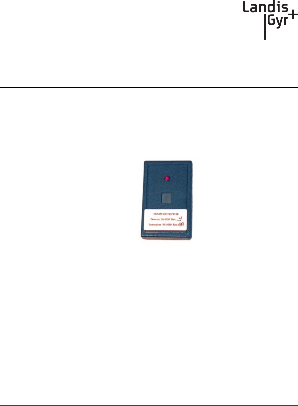
The part number for the RF Buster is 26-1050.
Figure B - 1. RF Buster
Before using the RF Buster, test it by pressing the button. The RF Buster’s LED lights red, and the
internal speaker sounds for approximately ½ second. If nothing happens, or if the LED lights and the
speaker sounds continuously, the 9V battery may be low. Replace the battery and repeat the test.
To access the battery compartment, open the spring-loaded cover on the back of the RF Buster. Take
care not to misplace the cover or damage the battery door spring mechanism.
DRAFT
24 Feb 2010
Appendix B - Using the RF Buster Landis+Gyr
38 98-1123 Rev AA Two-Way Gas Endpoint Installation Guide
Residential Meter Modules
1WiththeRFBusterLEDfacingyou,pressthebutton.
2PlacethecorneroftheRFBustercontainingthemagnetbythelocationofthereedswitchonthe
MeterModule.
3 Continuetopressthebutton.HoldtheRFBusterwithinsixinchesofthemodule.Themagnet
triggerstenRFtransmissionsfromthegasmodule,witheachtransmissionseparatedbyone
second.TheRFBusterLEDlightsandtheinternalspeakersoundsaboutone‐halfsecondfor
eachtransmissiondetected.
4Ifthemoduleisfunctional,itwilltransmit.
If the RF Buster does not detect a transmission from the module, store the RF Buster. Remove the
four module screws, place the module in its original packing bag, mark the module “defective,” and
return it to the meter shop.
.
Figure B - 2. Proper Placement of the RF Buster
DRAFT
24 Feb 2010

Two-Way Gas Endpoint Installation Guide 98-1123 Rev AA 39
AMR AutomatedMeterReading.Energyusedatagatheringfromutility
metersbyanymeansotherthanwalkinguptothemeter,lookingatthe
dials,andrecordingthemeterreadforbilling.
C.F.H. Cubicfeetperhour
CPR CellnetPulseRecorder:servesasacustomerendpointdeviceproviding
LANservicetometers;equippedwith“pulse”outputs.
DESServer DataExchangeServer
IDs Utility‐issuedidentificationtodenoteanindividualasanofficial
Installerfortheutility.
LAN LocalAreaNetwork:themostbasiclevelofthenetwork.TheLANisthe
constellationofendpoints,collectors,andconcentratorsthatfeeddata
upthroughthenetwork.
LP LoadProfile:methodofobtainingausagepattern,overaspanoftime,
foranenergycustomer,typicallybasedonintervalsof15,30,or60
minutes.
MRB ʺMaterialRepairBoardʺProcessofremovingmodulesfromthefield.
OCDB OperationsCenterDataBase.EndpointManagementsystemthatreports
tonetwork,exchangesinformationwiththeutilityandRIMS.
PersonalProtectiveEquipment PersonalProtectiveEquipment,allnecessaryequipmentusedforthe
safetyoftheinstallerwhileperformingworkonmeteringequipmentas
definedinthismanual.
PSR Packetsuccessrate:Numberofgooddatapacketsreceivedpertotal
numberofpacketssent,expressedasapercentage.
RIMS RetrofitInformationManagementSystem,anOracleprogram
managingtheshopfloorassemblyandprogrammingofmodules,also
standsformyriadofdatatables.ExchangesinformationwithOCDB.
GLOSSARY
DRAFT
24 Feb 2010
DRAFT
24 Feb 2010