Landis Gyr Technology ER6R1S2 M120 Module User Manual 15 0174 Exhibit Cover
Landis+Gyr Technology, Inc. M120 Module 15 0174 Exhibit Cover
Manual
5015 B.U. Bowman Drive Buford, GA 30518 USA Voice: 770-831-8048 Fax: 770-831-8598
Certification Exhibit
FCC ID: R7PER6R1S2
FCC Rule Part: 15.247, 15.249
ACS Project Number: 15-0174
Manufacturer: Landis+Gyr Technology, Inc.
Model: M120

LANDIS+GYR CONFIDENTIAL INFORMATION
M120 Module User Guide
Publication: 98-1718 Rev AA

Limitation on Warranties and Liability
Information in this document is subject to change without notice. This manual or any part of it thereof may not be re-
produced in any form unless permitted by contract or by written permission of Landis+Gyr.
In no event will Landis+Gyr be liable for any incidental, indirect, special, or consequential damages (including lost prof-
its) arising out of or relating to this publication or the information contained in it, even if Landis+Gyr has been advised,
knew, or should have known of the possibility of such damages.
© 2015 Landis+Gyr, Inc. All Rights Reserved
M120 Module User Guide
Publication: 98-1718
Revision History
Modification Date Revision Description Author
06/09/2015 AA Released Charlie Goerges
© 2015 Landis+Gyr • All rights reserved.

User Guide 98-1718 Rev AA 3
M120 Module User Guide
Introduction
The M120 is a battery operated module designed for automated gas meter reading. The M120 is
capable of recording gas consumption data from residential gas meters. It has a 2-way radio that is
compatible with electric meters, routers, and mesh extenders for relaying sensor data to the utility.
Federal Communication Commission (FCC)
Compliance Notice
This device complies with Part 15 of the FCC rules. Operation is subject to the following two
conditions:
1. This device may not cause harmful interference, and
2. This device must accept any interference received, including interference that may cause
undesired operation.
This equipment has been tested and found to comply with the limits for a Class B digital device,
pursuant to Part 15 of the FCC Rules. These limits are designed to provide reasonable protection
against harmful interference in a residential installation. This equipment generates, uses, and can
radiate radio frequency energy and, if not installed and used in accordance with the instructions, may
cause harmful interference to radio communications. However, there is no guarantee that
interference will not occur in a particular installation. If this equipment does cause harmful
interference to radio or television reception, which can be determined by turning the equipment off
and on, the user is encouraged to try to correct the interference by one or more of the following
measures:
1. Reorient or relocate the receiving antenna.
2. Increase the separation between the equipment and receiver.
3. Consult Landis+Gyr or an experienced radio technician for help.
UWARNING: Changes or modifications to this device not expressly approved by Landis+Gyr
will void the equipment warranty.

M120 Module User Guide Landis+Gyr
4 98-1718 Rev AA User Guide
Host FCC Label Requirements
The host label(s) must be clearly visible after the device is installed, and display the module FCC ID
in the following format:
Contains FCC ID: R7PER6R1S2
The following statement must also be clearly visible:
This device complies with part 15 of the
FCC Rules. Operation is subject to the
following two conditions:
(1) This device may not cause
harmful interference, and (2) this
device must accept any
interference received, including
interference that may cause
undesired operation.
RF Exposure Information
In accordance with FCC requirements of human exposure to radio frequency fields, the radiating
element shall be installed such that a minimum separation distance of 20 centimeters (8 inches) will
be maintained.
Electrical Characteristics
Battery:
•Battery type: Lithium-Manganese Dioxide
•Nominal voltage: 3.0 V
•Capacity: 4800 mAh
•Landis+Gyr Part number: 40-1235
DC Characteristics:
•Operating Voltage Range: 2.4 V - 3.3 V
•Typical Sleep Current: 7 uA
Radio Characteristics:
•Typical Antenna Gain: 0 dBi
•Frequency Range: 902 MHz - 928 MHz
•Modulation Format: FSK
•Transmit Output Power (typical)
•Single Channel Mode: - 27 dBm
•Frequency Hopping Mode: 24 dBm
•Receive sensitivity (typical)
Landis+Gyr M120 Module User Guide
User Guide 98-1718 Rev AA 5
•9.6 kbps: -112 dBm
•19.2 kbps: -110 dBm
•38.4 kbps: -108 dBm
•115.2 kbps: -101 dBm
•Max Input Power, No Damage: 10 dBm
Functional Description
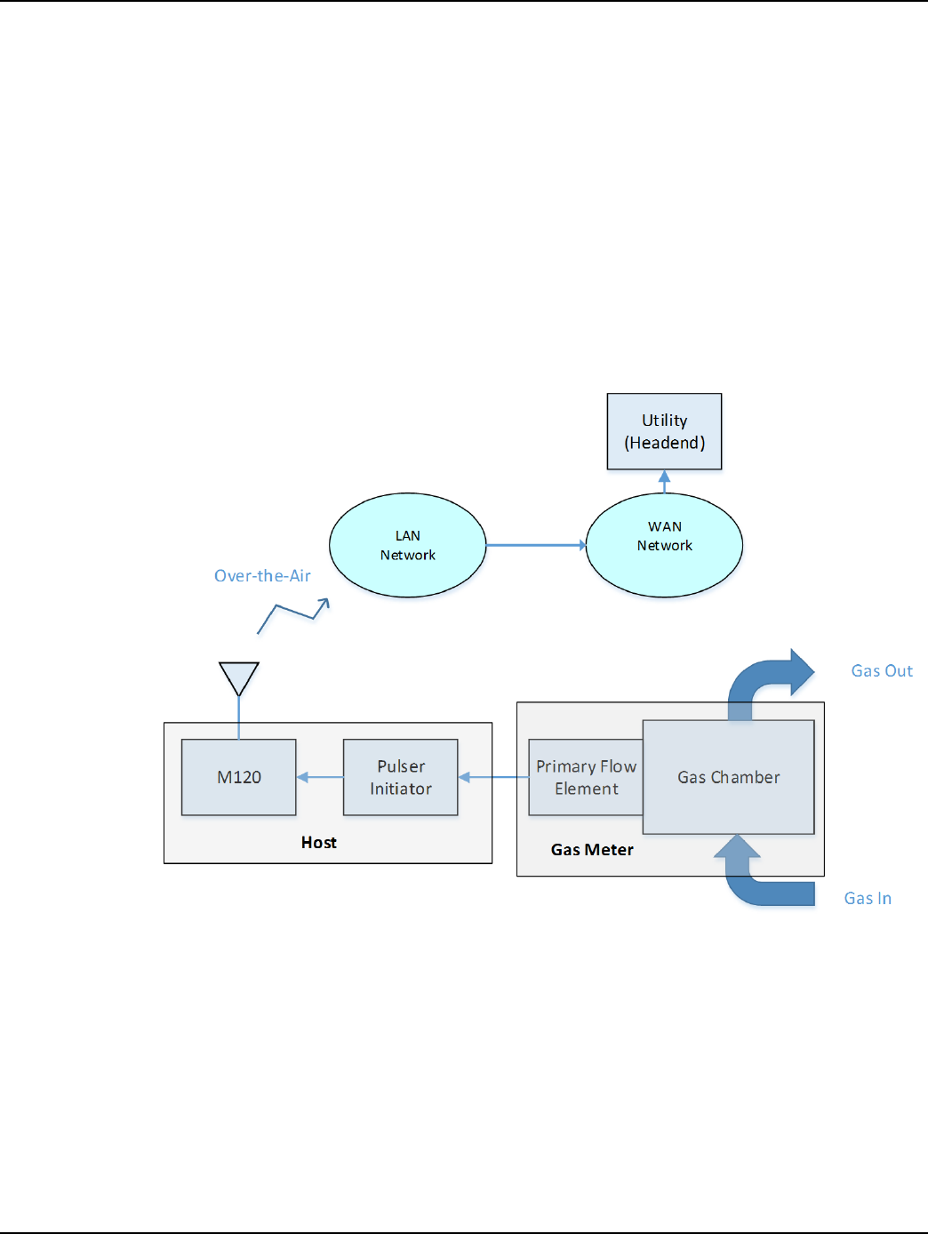
The M120 is a wireless battery endpoint for the application of automatic gas meter reading. The
primary function of the module is to record pulses that represent measurement of gas consumption,
and then deliver the data to the utility for processing. The block diagram below demonstrates this
operation.
Figure 1. Operation Block Diagram
The module is designed to record pulses from a Form-C type pulse initiator. The pulse initiator is a
sensor board that measures gas volume flow and relays the measurement to the M120 in the form of
electrical pulses.
The radio has two operating modes, frequency hopping and single channel. The frequency hopping
mode is the normal operating mode for network communication. The single channel mode is a low
power mode, and is primarily used for field diagnostic purposes.
M120 Module User Guide Landis+Gyr
6 98-1718 Rev AA User Guide
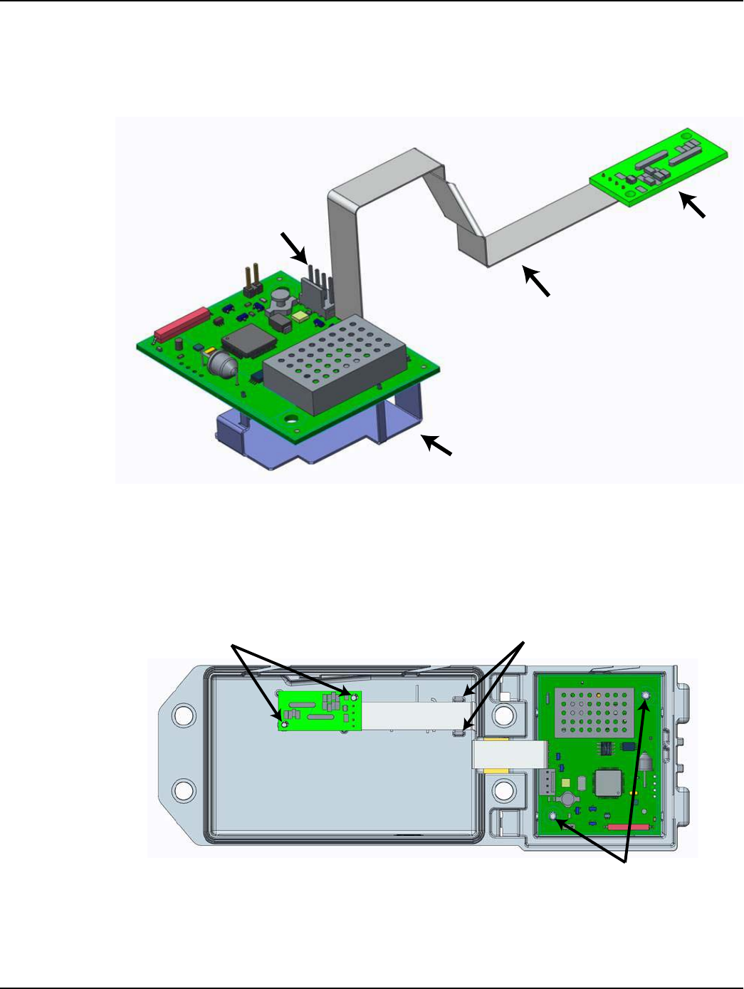
Host Installation
The battery is connected to the battery connector. The sensor board is connected to the M120
through a flex-cable. See picture below.
Figure 2. Sensor Board and Battery Connection to M120 Module
The M120 module and sensor board (pulse initiator) are designed to be heat-staked inside a plastic
enclosure. See picture below.
Figure 3. M120 Module and Sensor Board Staking Locations
Battery
Connector Sensor
Board
Flex Cable
M120
Module
HEAT STAKE THESE PINS
TO HOLD SENSOR BOARD
TO HOST
HEAT STAKE THESE PINS TO
HOLD FLEX-CABLE TO HOST
HEAT STAKE THESE TWO
PINS TO HOLD M120 TO HOST