Landis Gyr Technology ER6R1S4 Gridstream Enhanced Cellular, Focus AXe module User Manual 15 0421 Exhibit Cover
Landis+Gyr Technology, Inc. Gridstream Enhanced Cellular, Focus AXe module 15 0421 Exhibit Cover
UserManual.wiki
>
Landis Gyr Technology
>
ER6R1S4 User Manual
Manual
Navigation menu
Upload a User Manual
Namespaces
Wiki Guide
HTML
PDF
Info
Views
User Manual
Discussion / Help
Navigation

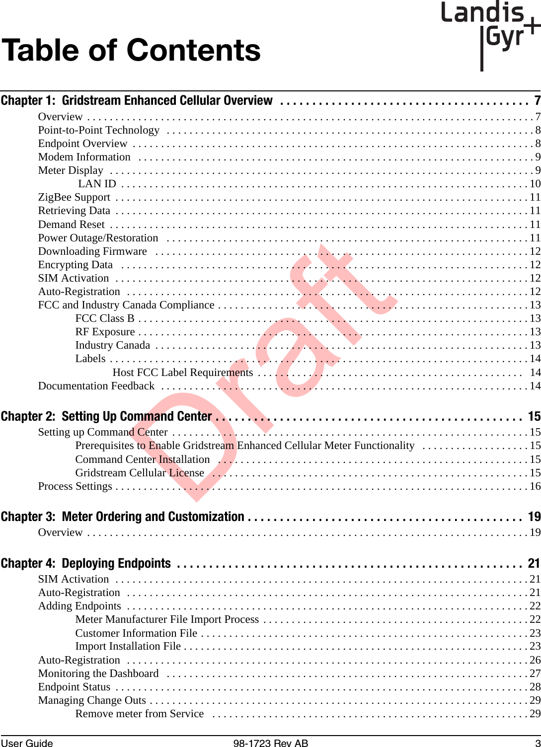


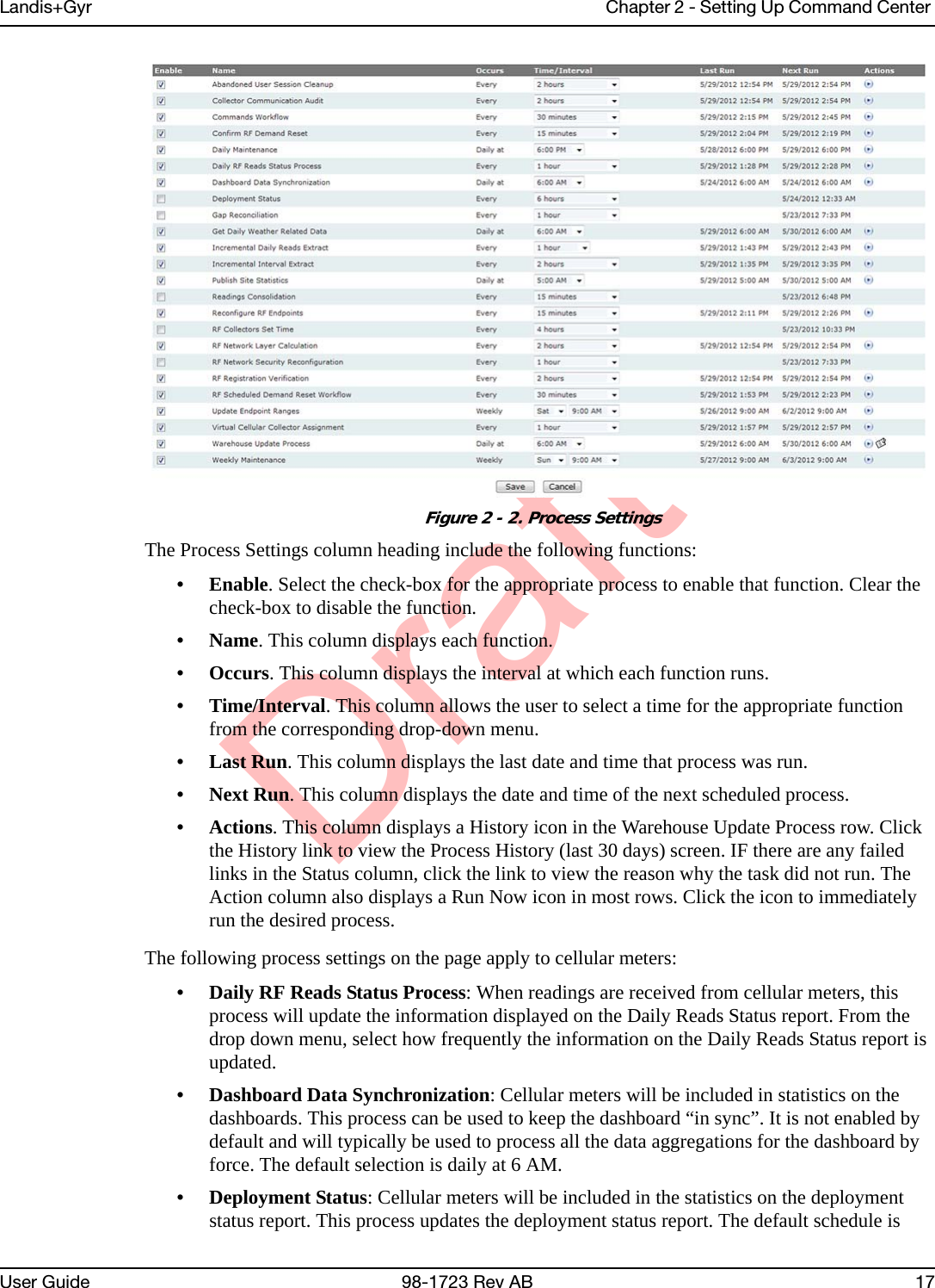

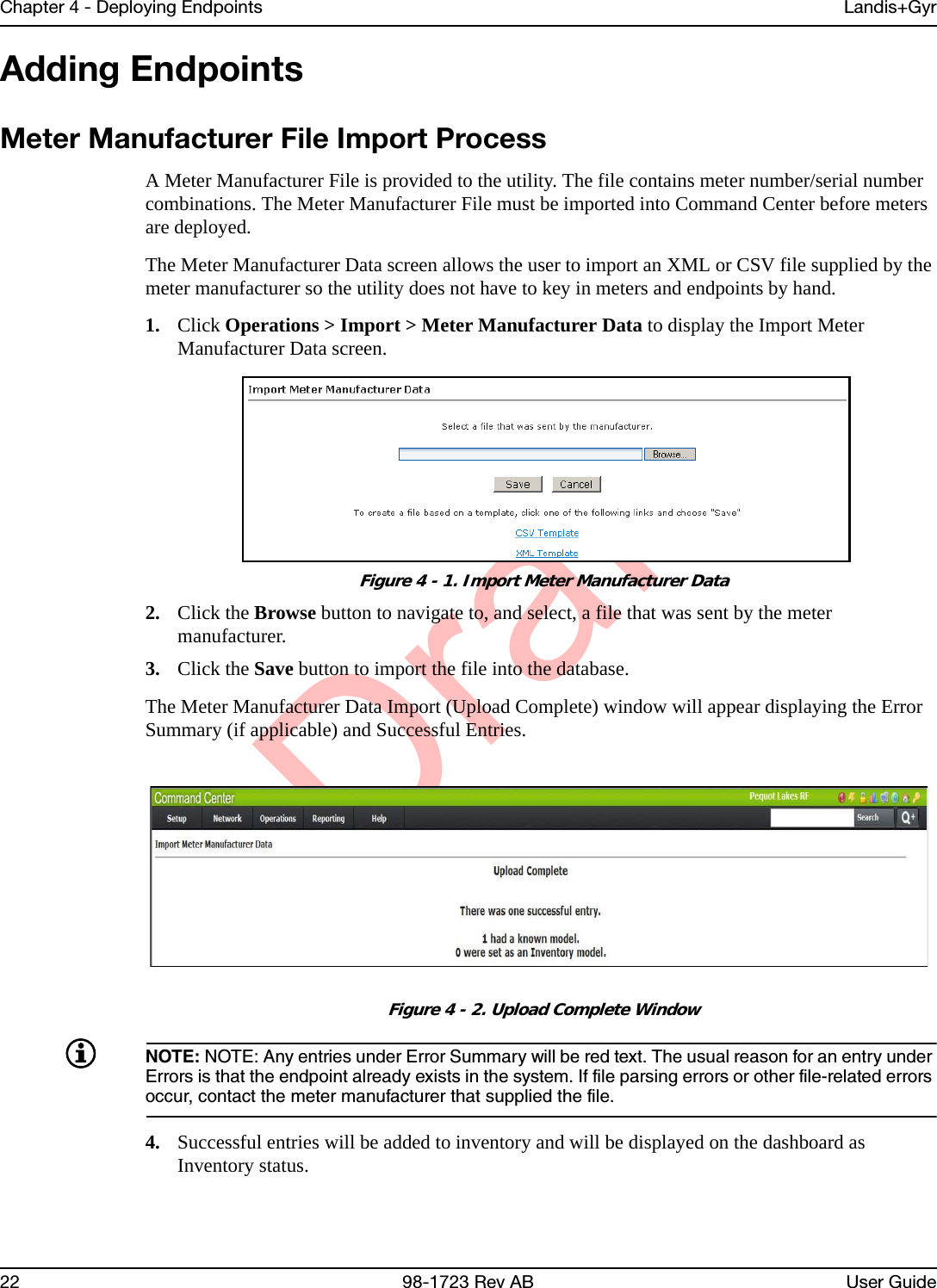
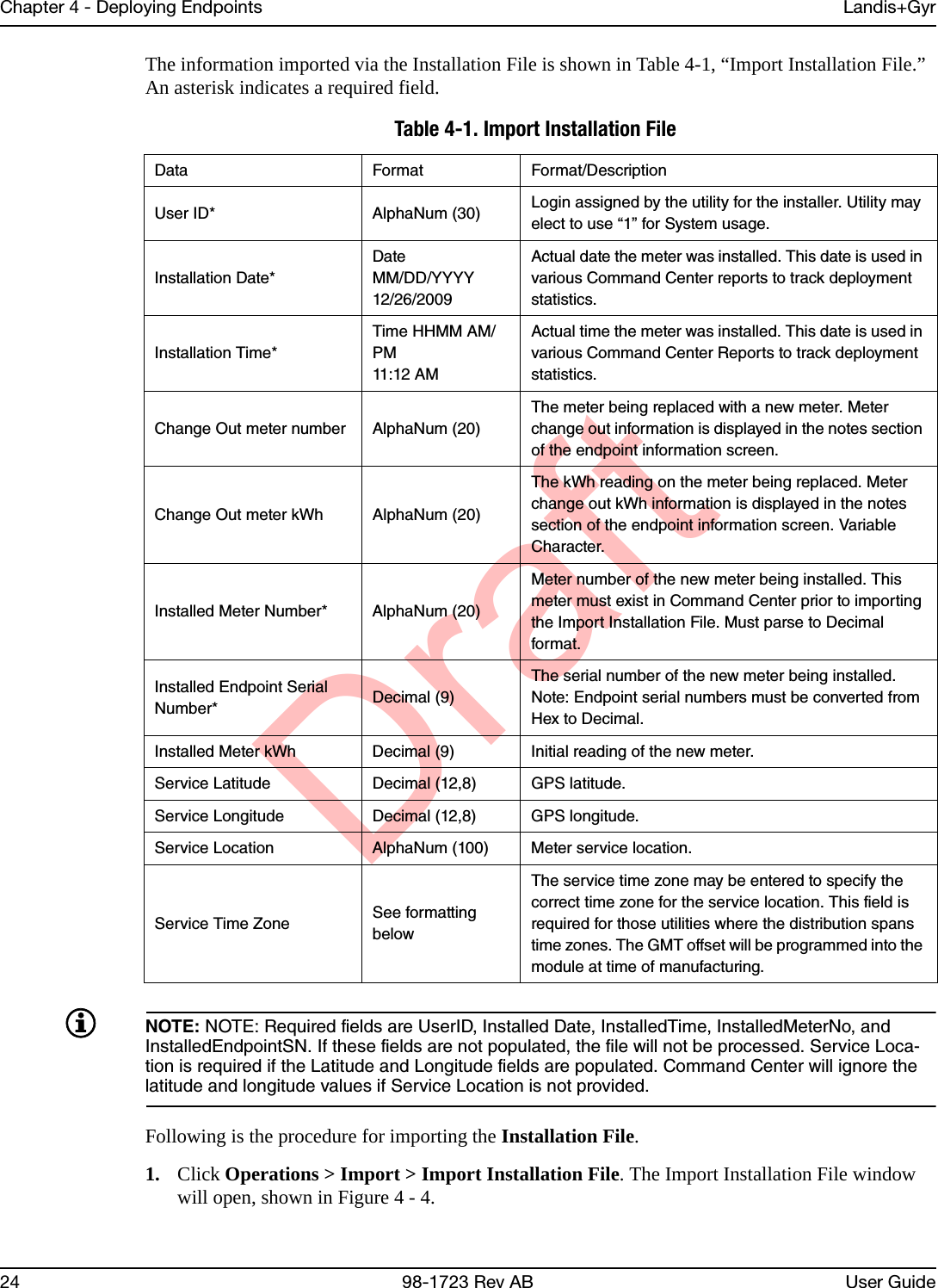
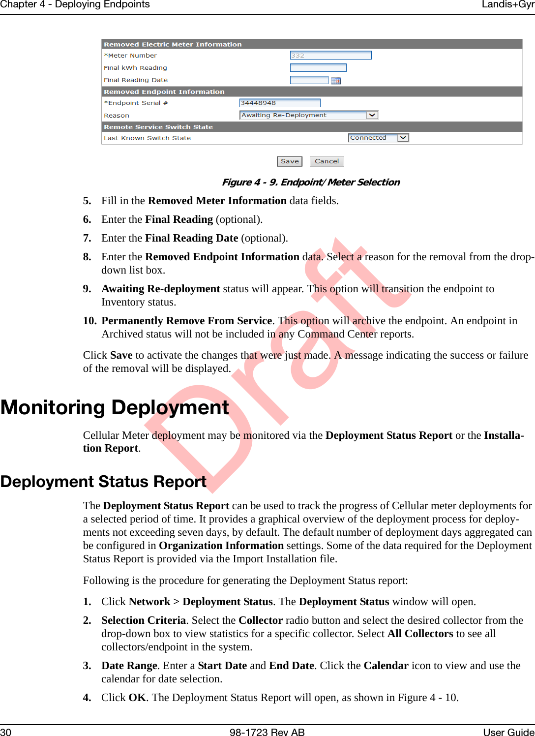
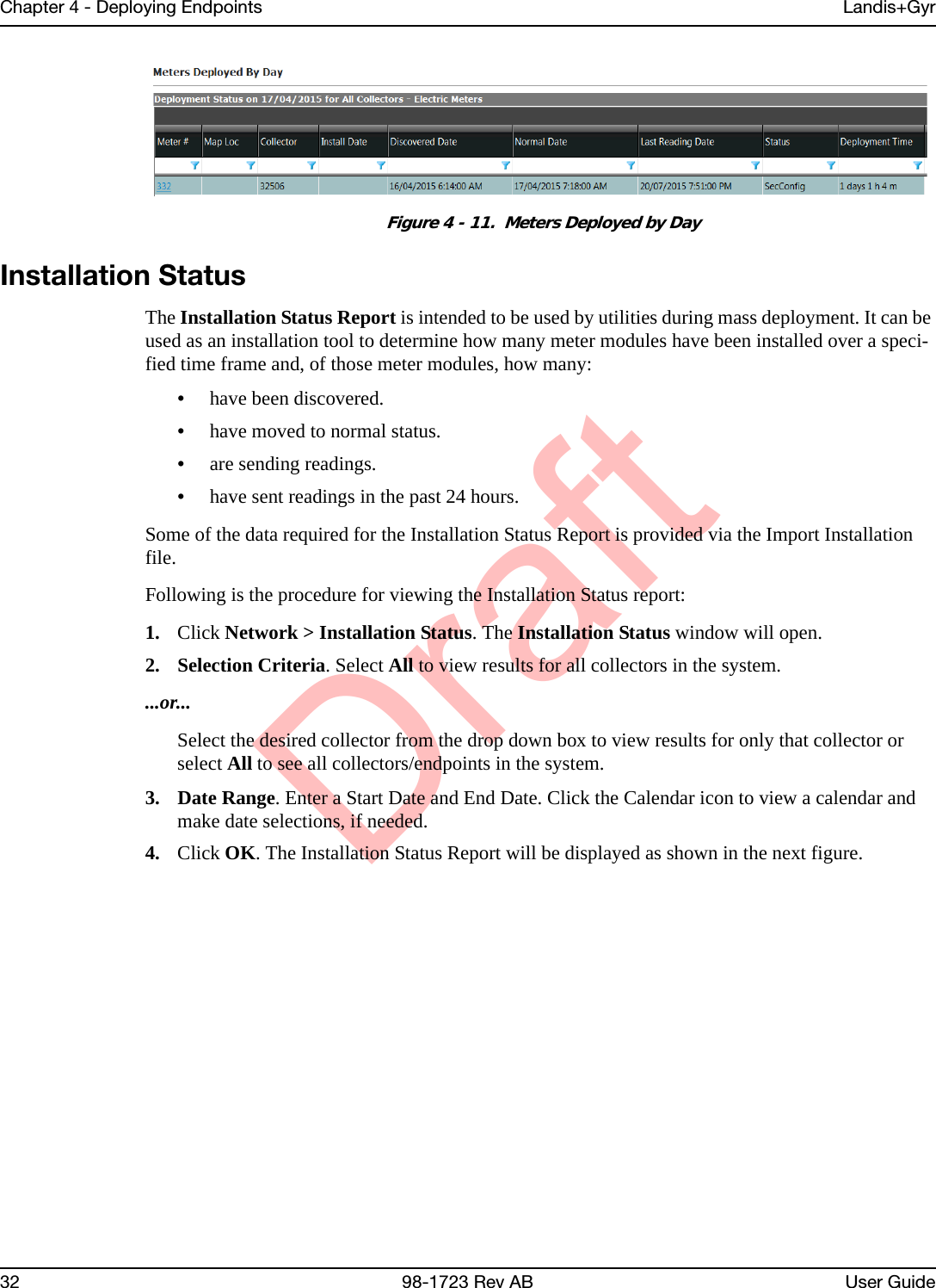


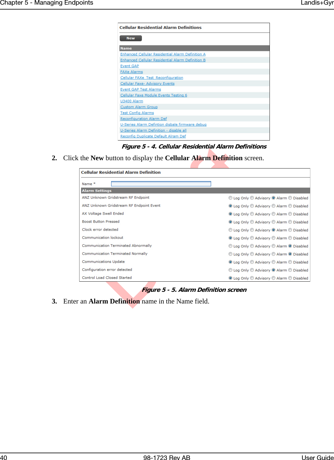
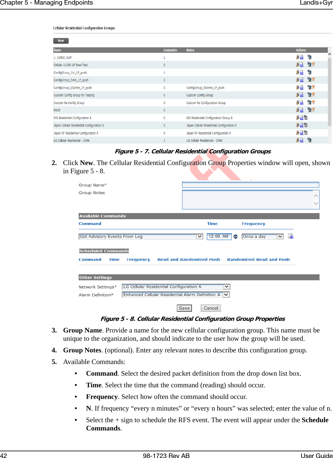
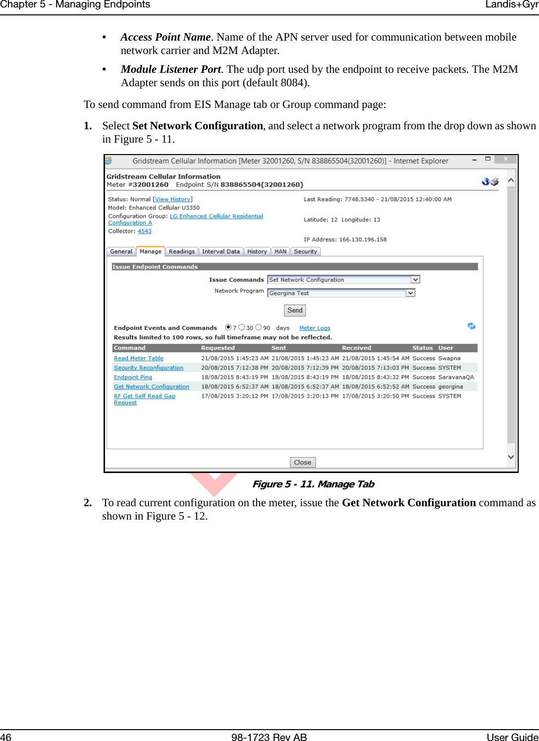
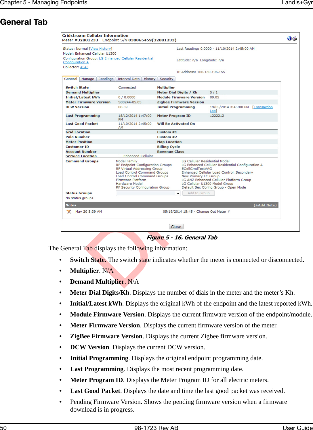
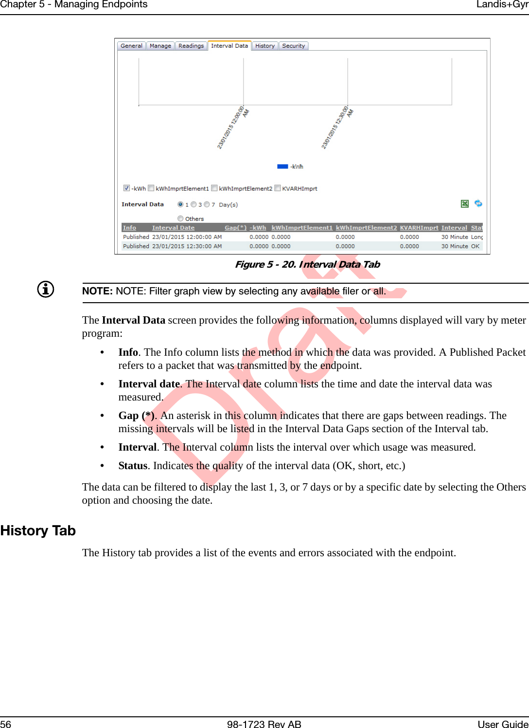
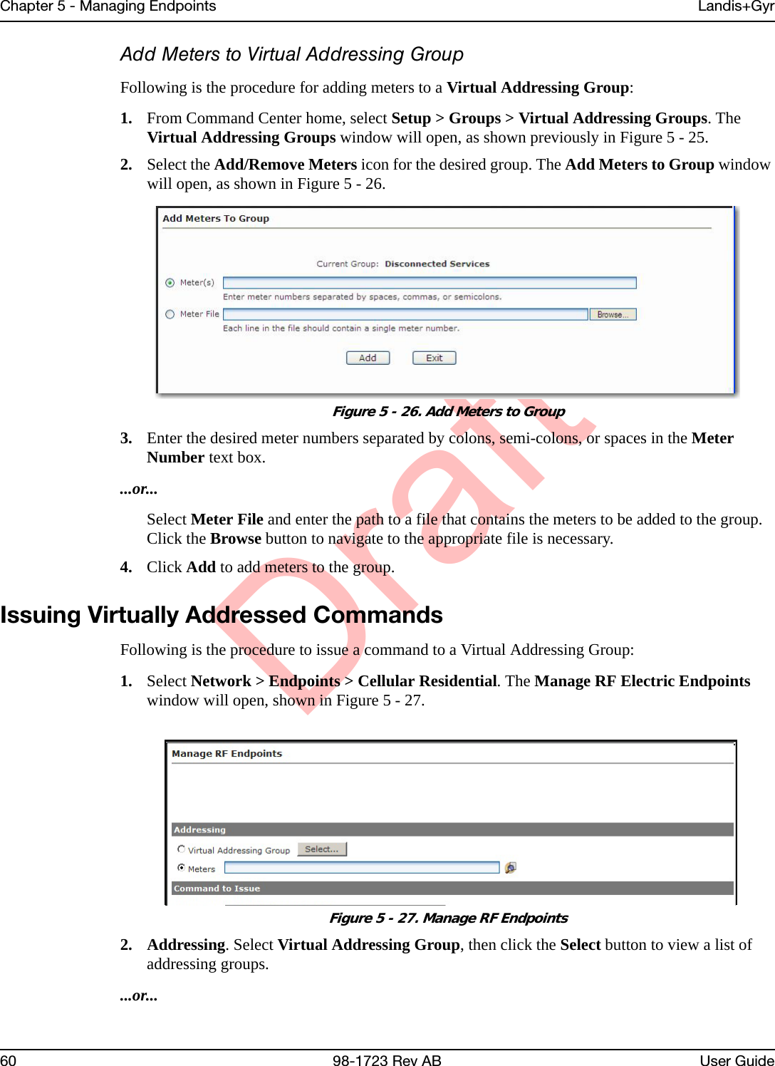

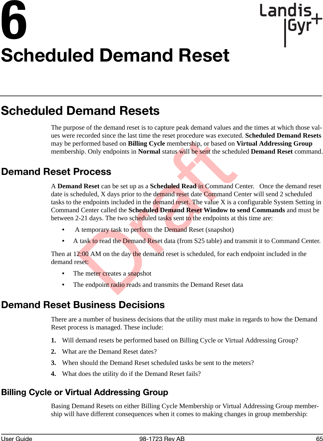
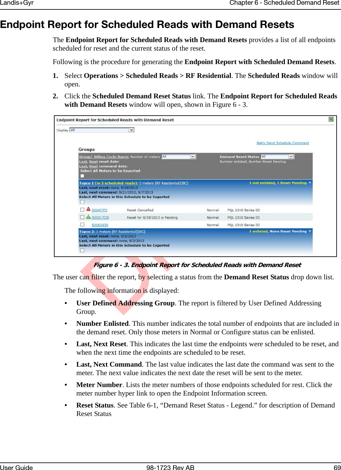
![DraftLandis+Gyr Chapter 6 - Scheduled Demand Reset User Guide 98-1723 Rev AB 67Scheduled Commands are sent on 11/5 to all meters in the Virtual Addressing Group.A meter added to the Virtual Addressing Group on 11/8 will receive the schedule for 11/10.Scheduled Read with Demand ResetFollowing is the procedure for creating a Scheduled Read with Demand Reset.1. Select Operations > Scheduled Reads > Cellular Residential. The Scheduled RF Residential Reads window will open, displaying any future Scheduled Reads.2. Click New. The Scheduled Residential Read window will open, shown in Figure 6 - 2.Figure 6 - 2. Scheduled Residential Read3. Name. Enter a name for the new scheduled read. The name must be unique to the organization.4. Reset Demand. The Reset Demand check box must be selected to initiate the demand reset process at the scheduled time. Once the Reset Demand check box is selected the On Demand Packet drop down list will be grayed out. It is not necessary to select a packet to be transmitted.5. Address Type. Select the desired Command Addressing Group(s) or select the desired Billing Cycle.6. Request Packet. Click On Specified dates to schedule the on-demand request for specific dates in the future. Enter the specific date(s) in the text box separated by spaces, commas, or semi-colons. ...or...Click the Recurring radio button and enter a Start Date. If needed, click the Calendar icon to generate a calendar from which to select a start date. Click the Show Recurrence Options radio button to display recurrence choices.• Do not repeat. The Scheduled Read will occur once.• Repeat every [1-2-3-4] week(s) on Sunday through Saturday. The Scheduled Read can be set to repeat every 1, 2, 3, or 4 weeks on any, or all, of the days of the week.](https://usermanual.wiki/Landis-Gyr-Technology/ER6R1S4/User-Guide-2928964-Page-68.png)
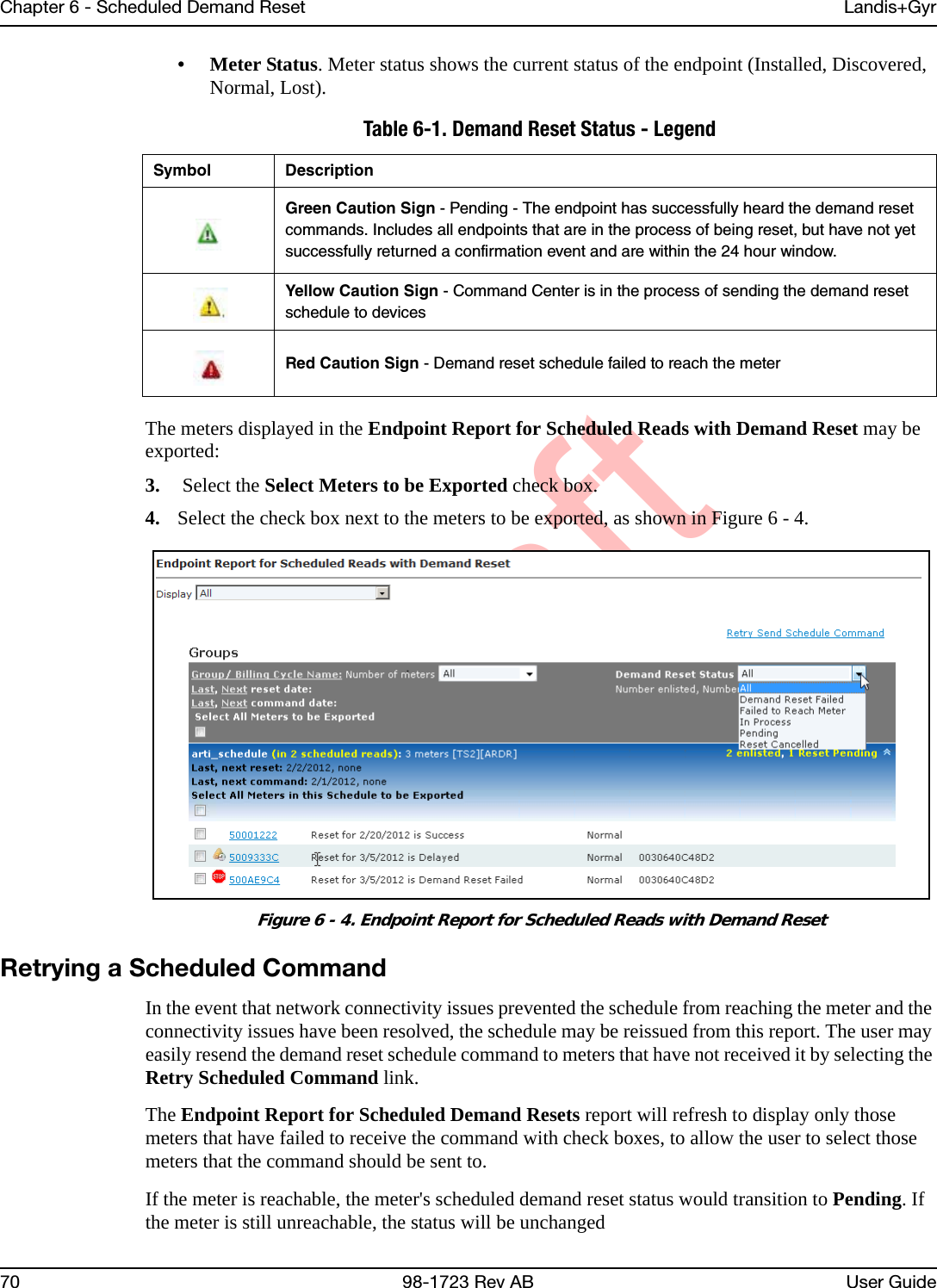
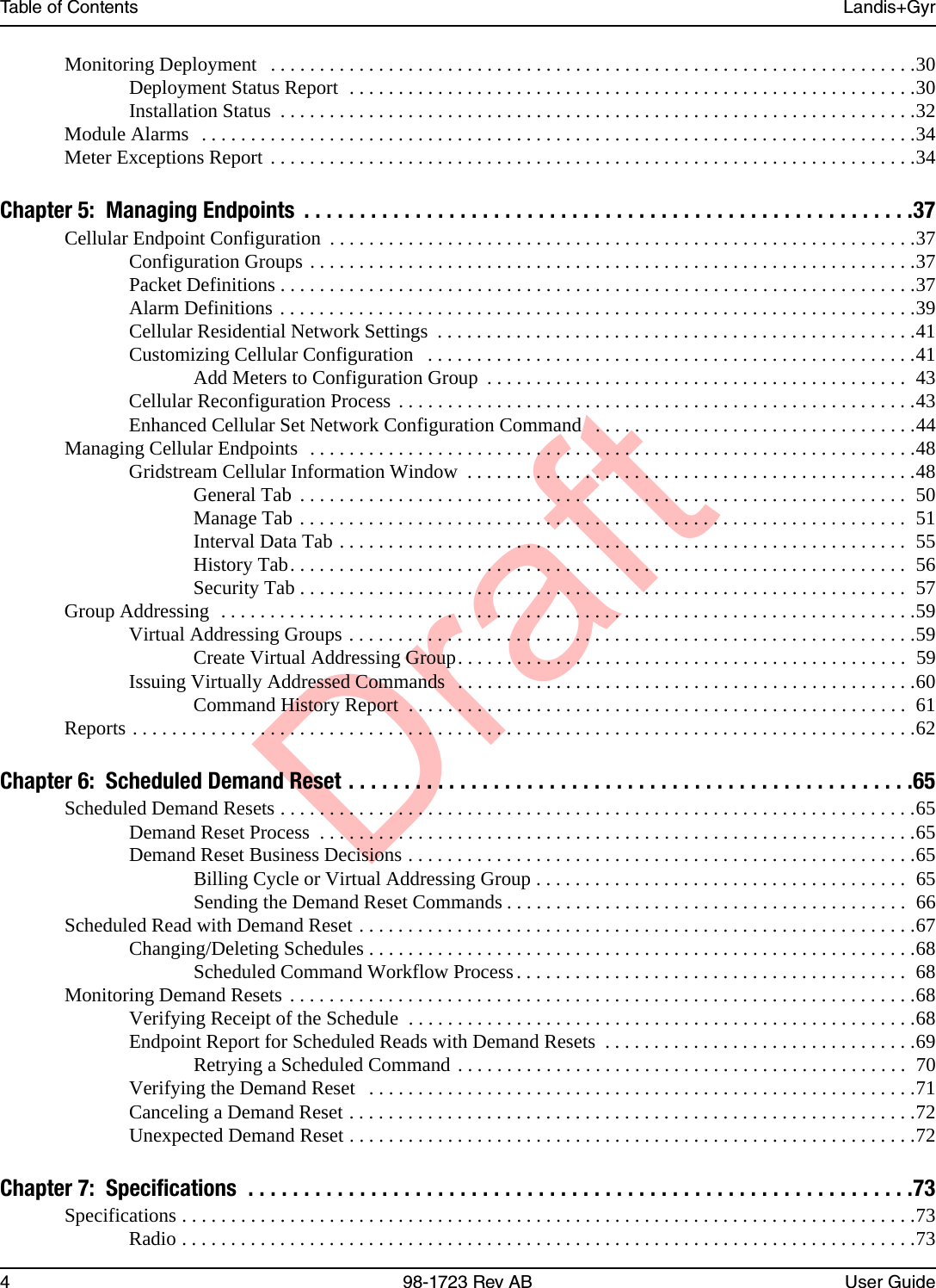
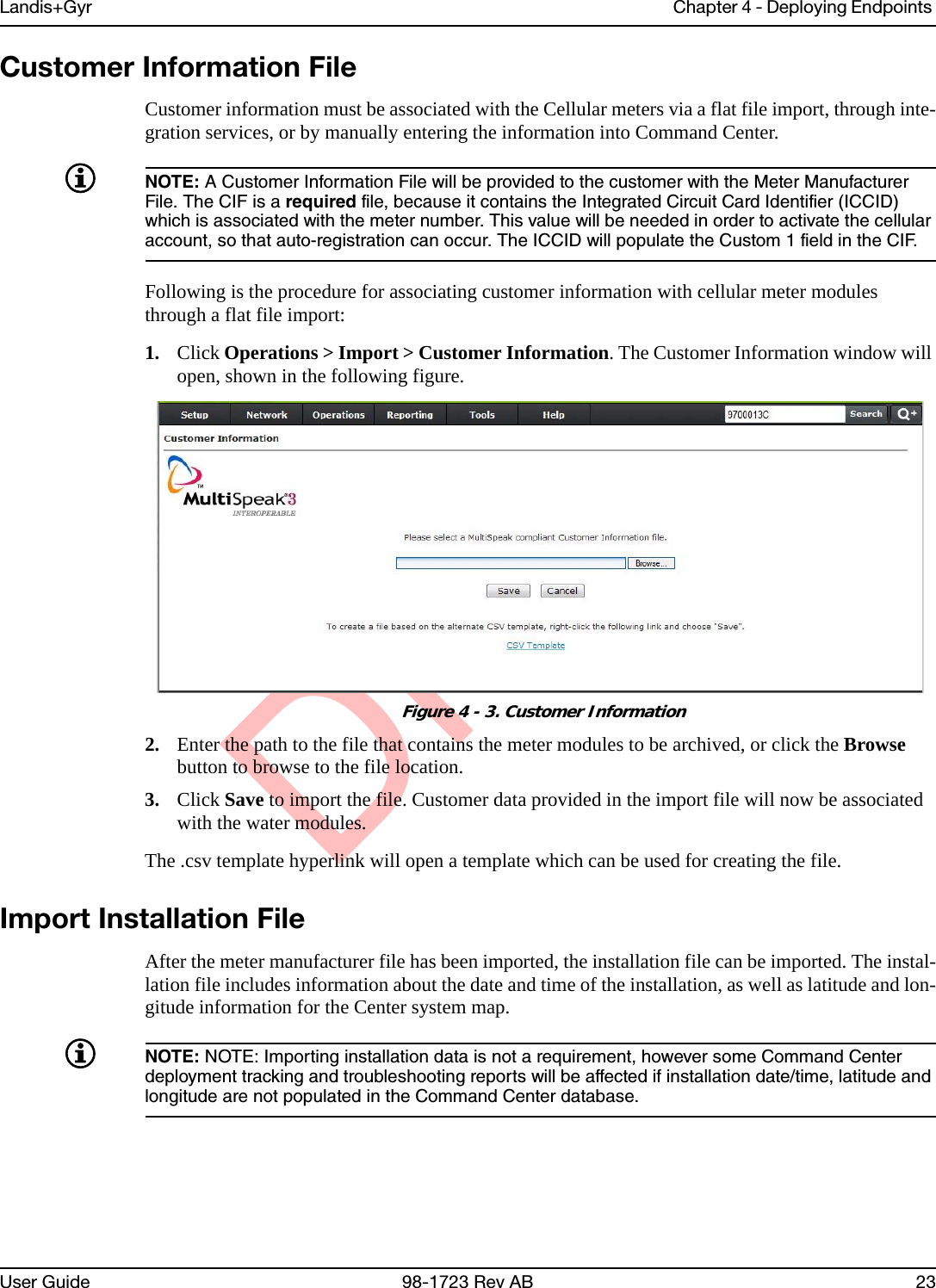
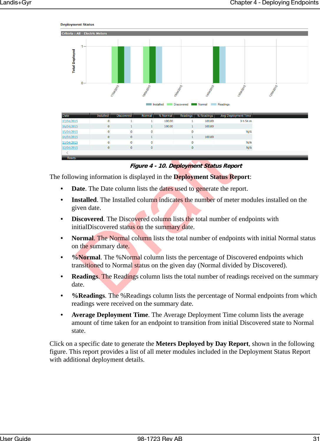
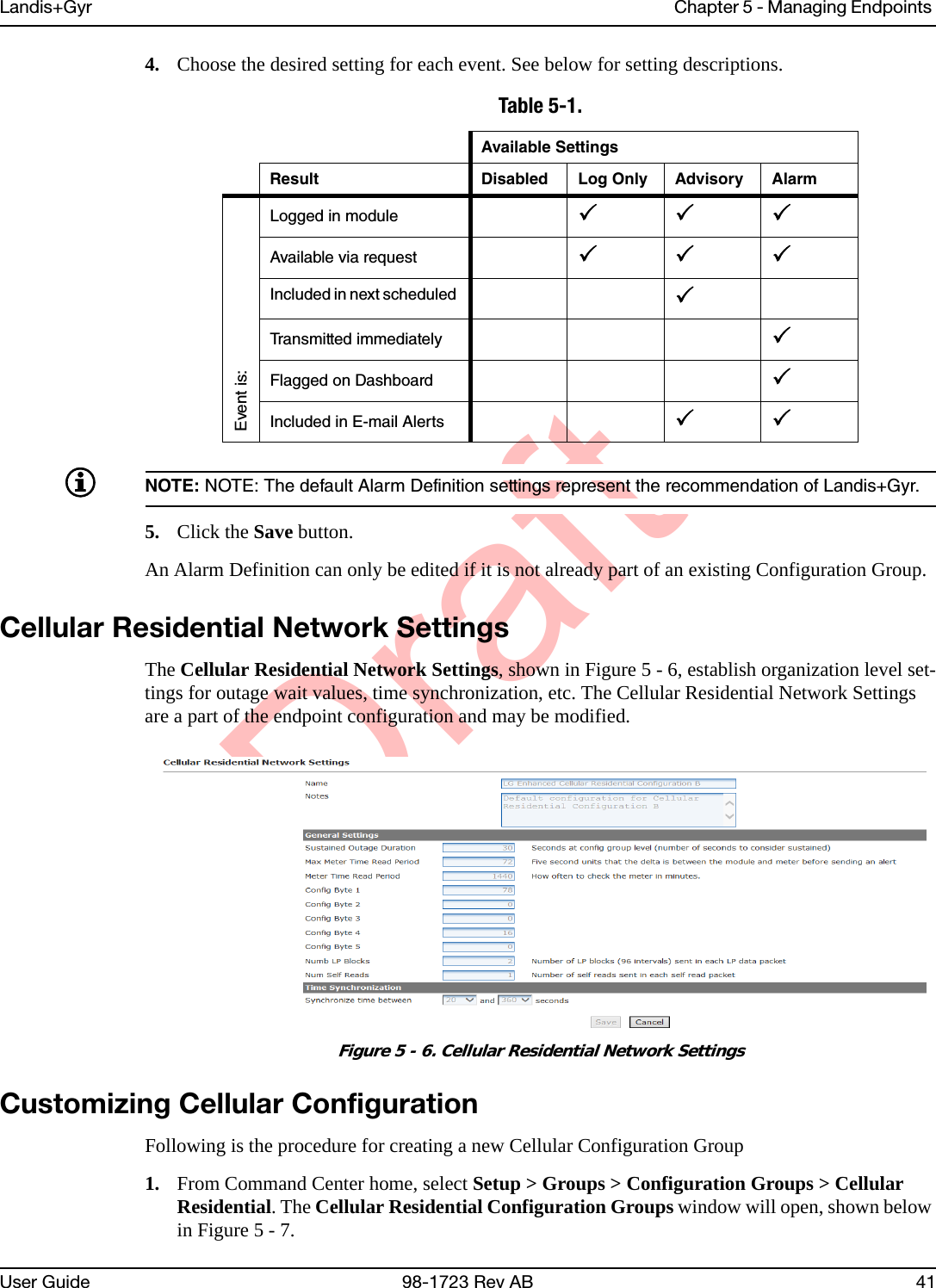
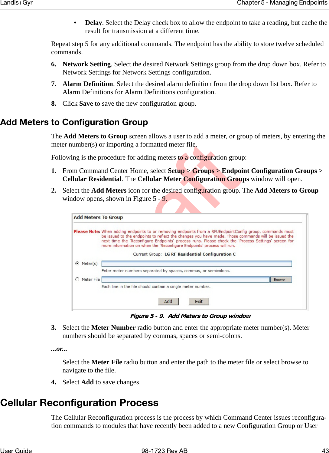
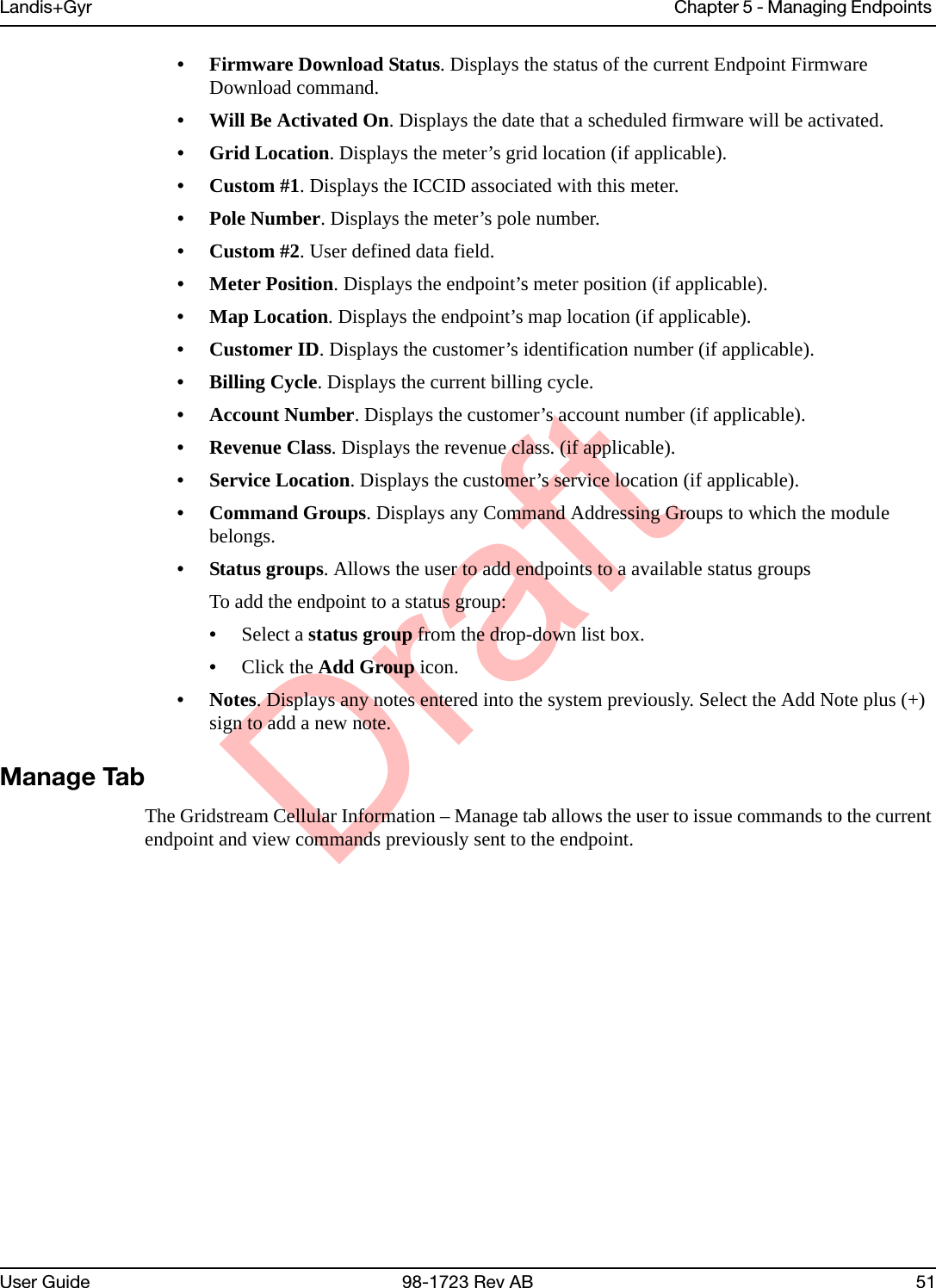
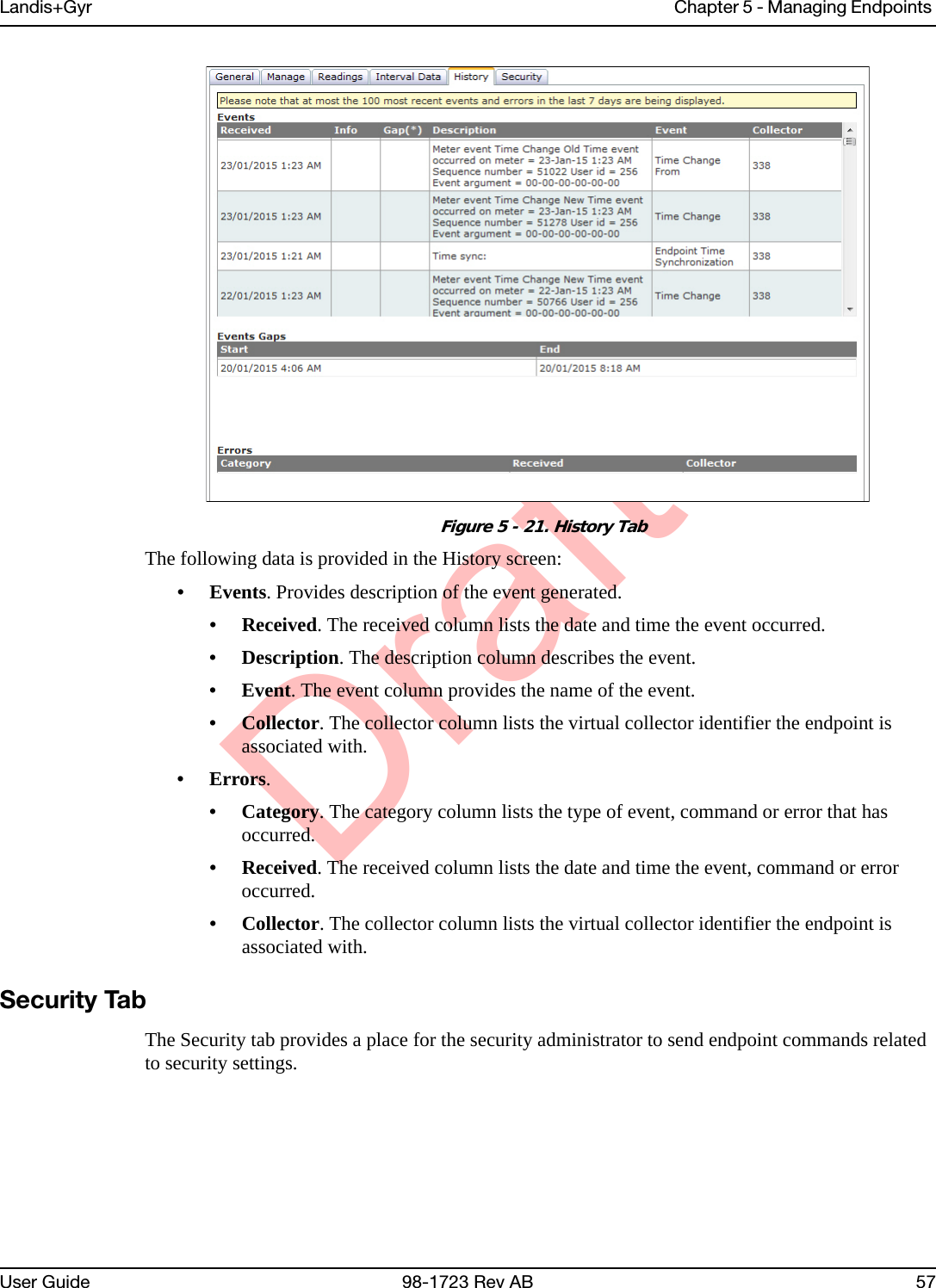
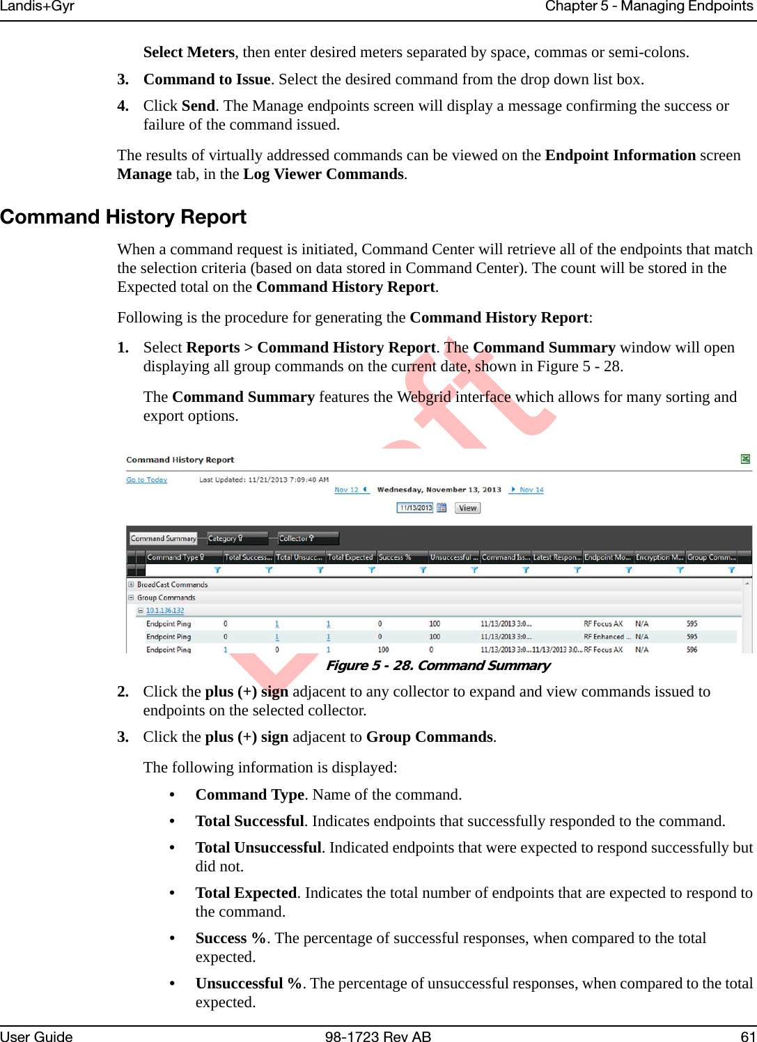
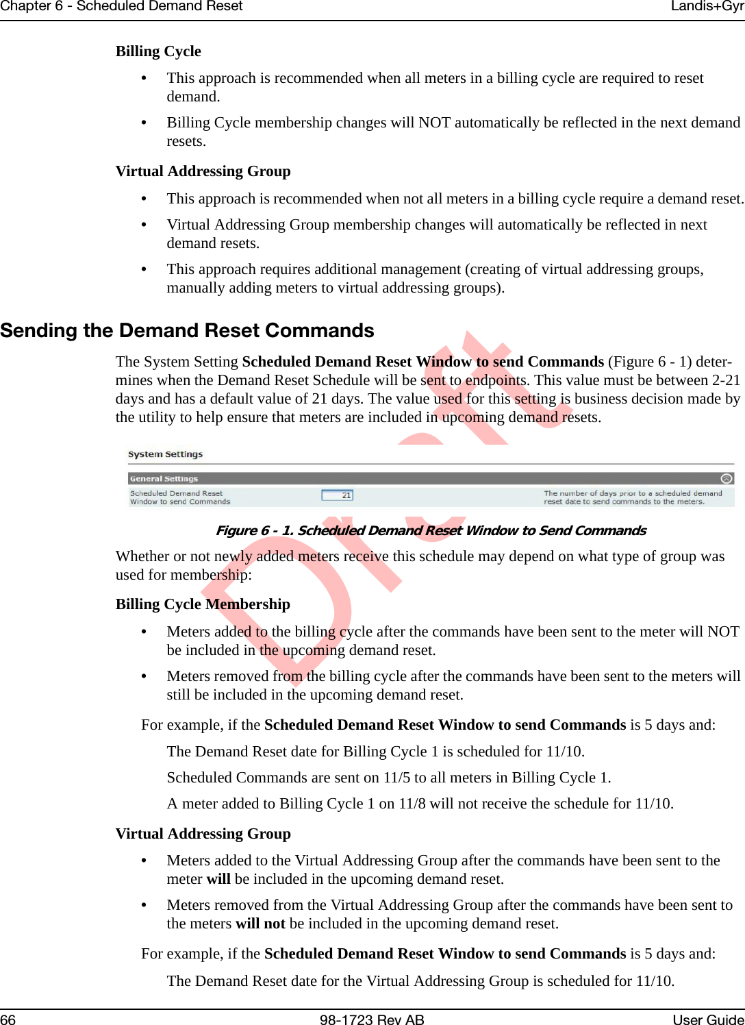
![DraftChapter 6 - Scheduled Demand Reset Landis+Gyr68 98-1723 Rev AB User Guide• Repeat on day [] of each month. The Scheduled Read can be set to repeat on the same date of each month. Enter a number from 1 to 31.• Repeat [] day(s) before the end of each month. The Scheduled Read can be set to repeat every month on a specified number of days before the last day of the month.If repeating...• Repeat until []. The Scheduled Read can be set to repeat until the user specified date by clicking the calendar icon and selecting the end date for the Scheduled Read.7. Click Save, to save the new Scheduled Read. The Scheduled RFU FocusAX Reads scheduled will open, displaying the new scheduled read.Changing/Deleting SchedulesA future schedule can be changed, deleted or copied on the main Scheduled Reads page.Schedule Changes.•If the temporary commands have already been sent down to the meter, Command Center will issue commands to remove the original schedule from the endpoint.•If the new schedule dates are within the next Scheduled Demand Reset Window to send Commands (default 21 days), Command Center will send the schedule to the endpoint. Schedule Deletes.•If the temporary commands have already been sent, Command Center will issue commands to remove the original schedule from the meter.Scheduled Command Workflow ProcessOnce the Demand Reset is scheduled, X days before the Demand Reset date (X = Window to Send Scheduled Commands) Command Center will issue a Send Scheduled Command command. The Process Setting RF Scheduled Demand Reset Workflow dictates how frequently Command Center will re-issue the Demand Reset commands to endpoints that have not acknowledged receipt of the schedule. By default, this process runs every 30 minutes with a maximum number of retries equal to 5. Monitoring Demand ResetsCommand Center monitors two aspects of the demand reset process:•Did the schedule reach the meters?•Did the demand reset occur as scheduled?Verifying Receipt of the ScheduleIndividual verification that the Send Scheduled Command was issued and reached a designated meter is visible on the individual Gridstream RF Endpoint Information - Manage tab. Group verification of the receipt of the scheduled commands by designated meters can be done via the Endpoint Report for Scheduled Reads with Demand Reset.](https://usermanual.wiki/Landis-Gyr-Technology/ER6R1S4/User-Guide-2928964-Page-69.png)