Landis Gyr Technology ER6R1S4 Gridstream Enhanced Cellular, Focus AXe module User Manual 15 0421 Exhibit Cover
Landis+Gyr Technology, Inc. Gridstream Enhanced Cellular, Focus AXe module 15 0421 Exhibit Cover
Manual

5015 B.U. Bowman Drive Buford, GA 30518 USA Voice: 770-831-8048 Fax: 770-831-8598
Certification Exhibit
FCC ID: R7PER6R1S4
IC: 5294A-ER6R1S4
FCC Rule Part: 15.247
IC Radio Standards Specification: RSS-247
ACS Project Number: 15-0421
Manufacturer: Landis+Gyr Technology, Inc.
Model: 26-7500
Manual

Draft
LANDIS+GYR CONFIDENTIAL INFORMATION
Gridstream Enhanced Cellular
FOCUS AXe User Guide
Publication: 98-1723 Rev AB

Draft
Limitation on Warranties and Liability
Information in this document is subject to change without notice. This manual or any part of it thereof may not be re-
produced in any form unless permitted by contract or by written permission of Landis+Gyr.
In no event will Landis+Gyr be liable for any incidental, indirect, special, or consequential damages (including lost prof-
its) arising out of or relating to this publication or the information contained in it, even if Landis+Gyr has been advised,
knew, or should have known of the possibility of such damages.
© 2015-2016 Landis+Gyr, Inc. All Rights Reserved
Gridstream Enhanced Cellular FOCUS AXe User Guide
Publication: 98-1723
Revision History
Modification Date Revision Description Author
08/27/2015 AA Released Charlie Goerges
02/23/2016 AB Released Charlie Goerges
© 2015-2016 Landis+Gyr • All rights reserved.

Draft
User Guide 98-1723 Rev AB 3
Table of Contents
Chapter 1: Gridstream Enhanced Cellular Overview . . . . . . . . . . . . . . . . . . . . . . . . . . . . . . . . . . . . . . . 7
Overview . . . . . . . . . . . . . . . . . . . . . . . . . . . . . . . . . . . . . . . . . . . . . . . . . . . . . . . . . . . . . . . . . . . . . . . . . . . . . . . 7
Point-to-Point Technology . . . . . . . . . . . . . . . . . . . . . . . . . . . . . . . . . . . . . . . . . . . . . . . . . . . . . . . . . . . . . . . . . 8
Endpoint Overview . . . . . . . . . . . . . . . . . . . . . . . . . . . . . . . . . . . . . . . . . . . . . . . . . . . . . . . . . . . . . . . . . . . . . . . 8
Modem Information . . . . . . . . . . . . . . . . . . . . . . . . . . . . . . . . . . . . . . . . . . . . . . . . . . . . . . . . . . . . . . . . . . . . . . 9
Meter Display . . . . . . . . . . . . . . . . . . . . . . . . . . . . . . . . . . . . . . . . . . . . . . . . . . . . . . . . . . . . . . . . . . . . . . . . . . . 9
LAN ID . . . . . . . . . . . . . . . . . . . . . . . . . . . . . . . . . . . . . . . . . . . . . . . . . . . . . . . . . . . . . . . . . . . . . . . . 10
ZigBee Support . . . . . . . . . . . . . . . . . . . . . . . . . . . . . . . . . . . . . . . . . . . . . . . . . . . . . . . . . . . . . . . . . . . . . . . . .11
Retrieving Data . . . . . . . . . . . . . . . . . . . . . . . . . . . . . . . . . . . . . . . . . . . . . . . . . . . . . . . . . . . . . . . . . . . . . . . . . 11
Demand Reset . . . . . . . . . . . . . . . . . . . . . . . . . . . . . . . . . . . . . . . . . . . . . . . . . . . . . . . . . . . . . . . . . . . . . . . . . .11
Power Outage/Restoration . . . . . . . . . . . . . . . . . . . . . . . . . . . . . . . . . . . . . . . . . . . . . . . . . . . . . . . . . . . . . . . . 11
Downloading Firmware . . . . . . . . . . . . . . . . . . . . . . . . . . . . . . . . . . . . . . . . . . . . . . . . . . . . . . . . . . . . . . . . . . 12
Encrypting Data . . . . . . . . . . . . . . . . . . . . . . . . . . . . . . . . . . . . . . . . . . . . . . . . . . . . . . . . . . . . . . . . . . . . . . . . 12
SIM Activation . . . . . . . . . . . . . . . . . . . . . . . . . . . . . . . . . . . . . . . . . . . . . . . . . . . . . . . . . . . . . . . . . . . . . . . . . 12
Auto-Registration . . . . . . . . . . . . . . . . . . . . . . . . . . . . . . . . . . . . . . . . . . . . . . . . . . . . . . . . . . . . . . . . . . . . . . .12
FCC and Industry Canada Compliance . . . . . . . . . . . . . . . . . . . . . . . . . . . . . . . . . . . . . . . . . . . . . . . . . . . . . . .13
FCC Class B . . . . . . . . . . . . . . . . . . . . . . . . . . . . . . . . . . . . . . . . . . . . . . . . . . . . . . . . . . . . . . . . . . . . .13
RF Exposure . . . . . . . . . . . . . . . . . . . . . . . . . . . . . . . . . . . . . . . . . . . . . . . . . . . . . . . . . . . . . . . . . . . . . 13
Industry Canada . . . . . . . . . . . . . . . . . . . . . . . . . . . . . . . . . . . . . . . . . . . . . . . . . . . . . . . . . . . . . . . . . . 13
Labels . . . . . . . . . . . . . . . . . . . . . . . . . . . . . . . . . . . . . . . . . . . . . . . . . . . . . . . . . . . . . . . . . . . . . . . . . . 14
Host FCC Label Requirements . . . . . . . . . . . . . . . . . . . . . . . . . . . . . . . . . . . . . . . . . . . . . . . 14
Documentation Feedback . . . . . . . . . . . . . . . . . . . . . . . . . . . . . . . . . . . . . . . . . . . . . . . . . . . . . . . . . . . . . . . . . 14
Chapter 2: Setting Up Command Center . . . . . . . . . . . . . . . . . . . . . . . . . . . . . . . . . . . . . . . . . . . . . . . . 15
Setting up Command Center . . . . . . . . . . . . . . . . . . . . . . . . . . . . . . . . . . . . . . . . . . . . . . . . . . . . . . . . . . . . . . . 15
Prerequisites to Enable Gridstream Enhanced Cellular Meter Functionality . . . . . . . . . . . . . . . . . . .15
Command Center Installation . . . . . . . . . . . . . . . . . . . . . . . . . . . . . . . . . . . . . . . . . . . . . . . . . . . . . . . 15
Gridstream Cellular License . . . . . . . . . . . . . . . . . . . . . . . . . . . . . . . . . . . . . . . . . . . . . . . . . . . . . . . . 15
Process Settings . . . . . . . . . . . . . . . . . . . . . . . . . . . . . . . . . . . . . . . . . . . . . . . . . . . . . . . . . . . . . . . . . . . . . . . . .16
Chapter 3: Meter Ordering and Customization . . . . . . . . . . . . . . . . . . . . . . . . . . . . . . . . . . . . . . . . . . . 19
Overview . . . . . . . . . . . . . . . . . . . . . . . . . . . . . . . . . . . . . . . . . . . . . . . . . . . . . . . . . . . . . . . . . . . . . . . . . . . . . . 19
Chapter 4: Deploying Endpoints . . . . . . . . . . . . . . . . . . . . . . . . . . . . . . . . . . . . . . . . . . . . . . . . . . . . . . 21
SIM Activation . . . . . . . . . . . . . . . . . . . . . . . . . . . . . . . . . . . . . . . . . . . . . . . . . . . . . . . . . . . . . . . . . . . . . . . . .21
Auto-Registration . . . . . . . . . . . . . . . . . . . . . . . . . . . . . . . . . . . . . . . . . . . . . . . . . . . . . . . . . . . . . . . . . . . . . . . 21
Adding Endpoints . . . . . . . . . . . . . . . . . . . . . . . . . . . . . . . . . . . . . . . . . . . . . . . . . . . . . . . . . . . . . . . . . . . . . . .22
Meter Manufacturer File Import Process . . . . . . . . . . . . . . . . . . . . . . . . . . . . . . . . . . . . . . . . . . . . . . .22
Customer Information File . . . . . . . . . . . . . . . . . . . . . . . . . . . . . . . . . . . . . . . . . . . . . . . . . . . . . . . . . . 23
Import Installation File . . . . . . . . . . . . . . . . . . . . . . . . . . . . . . . . . . . . . . . . . . . . . . . . . . . . . . . . . . . . .23
Auto-Registration . . . . . . . . . . . . . . . . . . . . . . . . . . . . . . . . . . . . . . . . . . . . . . . . . . . . . . . . . . . . . . . . . . . . . . .26
Monitoring the Dashboard . . . . . . . . . . . . . . . . . . . . . . . . . . . . . . . . . . . . . . . . . . . . . . . . . . . . . . . . . . . . . . . . 27
Endpoint Status . . . . . . . . . . . . . . . . . . . . . . . . . . . . . . . . . . . . . . . . . . . . . . . . . . . . . . . . . . . . . . . . . . . . . . . . .28
Managing Change Outs . . . . . . . . . . . . . . . . . . . . . . . . . . . . . . . . . . . . . . . . . . . . . . . . . . . . . . . . . . . . . . . . . . . 29
Remove meter from Service . . . . . . . . . . . . . . . . . . . . . . . . . . . . . . . . . . . . . . . . . . . . . . . . . . . . . . . . 29

Draft
Table of Contents Landis+Gyr
4 98-1723 Rev AB User Guide
Monitoring Deployment . . . . . . . . . . . . . . . . . . . . . . . . . . . . . . . . . . . . . . . . . . . . . . . . . . . . . . . . . . . . . . . . . .30
Deployment Status Report . . . . . . . . . . . . . . . . . . . . . . . . . . . . . . . . . . . . . . . . . . . . . . . . . . . . . . . . . .30
Installation Status . . . . . . . . . . . . . . . . . . . . . . . . . . . . . . . . . . . . . . . . . . . . . . . . . . . . . . . . . . . . . . . . .32
Module Alarms . . . . . . . . . . . . . . . . . . . . . . . . . . . . . . . . . . . . . . . . . . . . . . . . . . . . . . . . . . . . . . . . . . . . . . . . .34
Meter Exceptions Report . . . . . . . . . . . . . . . . . . . . . . . . . . . . . . . . . . . . . . . . . . . . . . . . . . . . . . . . . . . . . . . . . .34
Chapter 5: Managing Endpoints . . . . . . . . . . . . . . . . . . . . . . . . . . . . . . . . . . . . . . . . . . . . . . . . . . . . . . .37
Cellular Endpoint Configuration . . . . . . . . . . . . . . . . . . . . . . . . . . . . . . . . . . . . . . . . . . . . . . . . . . . . . . . . . . . .37
Configuration Groups . . . . . . . . . . . . . . . . . . . . . . . . . . . . . . . . . . . . . . . . . . . . . . . . . . . . . . . . . . . . . .37
Packet Definitions . . . . . . . . . . . . . . . . . . . . . . . . . . . . . . . . . . . . . . . . . . . . . . . . . . . . . . . . . . . . . . . . .37
Alarm Definitions . . . . . . . . . . . . . . . . . . . . . . . . . . . . . . . . . . . . . . . . . . . . . . . . . . . . . . . . . . . . . . . . .39
Cellular Residential Network Settings . . . . . . . . . . . . . . . . . . . . . . . . . . . . . . . . . . . . . . . . . . . . . . . . .41
Customizing Cellular Configuration . . . . . . . . . . . . . . . . . . . . . . . . . . . . . . . . . . . . . . . . . . . . . . . . . .41
Add Meters to Configuration Group . . . . . . . . . . . . . . . . . . . . . . . . . . . . . . . . . . . . . . . . . . . 43
Cellular Reconfiguration Process . . . . . . . . . . . . . . . . . . . . . . . . . . . . . . . . . . . . . . . . . . . . . . . . . . . . .43
Enhanced Cellular Set Network Configuration Command . . . . . . . . . . . . . . . . . . . . . . . . . . . . . . . . .44
Managing Cellular Endpoints . . . . . . . . . . . . . . . . . . . . . . . . . . . . . . . . . . . . . . . . . . . . . . . . . . . . . . . . . . . . . .48
Gridstream Cellular Information Window . . . . . . . . . . . . . . . . . . . . . . . . . . . . . . . . . . . . . . . . . . . . . .48
General Tab . . . . . . . . . . . . . . . . . . . . . . . . . . . . . . . . . . . . . . . . . . . . . . . . . . . . . . . . . . . . . . 50
Manage Tab . . . . . . . . . . . . . . . . . . . . . . . . . . . . . . . . . . . . . . . . . . . . . . . . . . . . . . . . . . . . . . 51
Interval Data Tab . . . . . . . . . . . . . . . . . . . . . . . . . . . . . . . . . . . . . . . . . . . . . . . . . . . . . . . . . . 55
History Tab. . . . . . . . . . . . . . . . . . . . . . . . . . . . . . . . . . . . . . . . . . . . . . . . . . . . . . . . . . . . . . . 56
Security Tab . . . . . . . . . . . . . . . . . . . . . . . . . . . . . . . . . . . . . . . . . . . . . . . . . . . . . . . . . . . . . . 57
Group Addressing . . . . . . . . . . . . . . . . . . . . . . . . . . . . . . . . . . . . . . . . . . . . . . . . . . . . . . . . . . . . . . . . . . . . . . .59
Virtual Addressing Groups . . . . . . . . . . . . . . . . . . . . . . . . . . . . . . . . . . . . . . . . . . . . . . . . . . . . . . . . . .59
Create Virtual Addressing Group. . . . . . . . . . . . . . . . . . . . . . . . . . . . . . . . . . . . . . . . . . . . . . 59
Issuing Virtually Addressed Commands . . . . . . . . . . . . . . . . . . . . . . . . . . . . . . . . . . . . . . . . . . . . . . .60
Command History Report . . . . . . . . . . . . . . . . . . . . . . . . . . . . . . . . . . . . . . . . . . . . . . . . . . . 61
Reports . . . . . . . . . . . . . . . . . . . . . . . . . . . . . . . . . . . . . . . . . . . . . . . . . . . . . . . . . . . . . . . . . . . . . . . . . . . . . . . .62
Chapter 6: Scheduled Demand Reset . . . . . . . . . . . . . . . . . . . . . . . . . . . . . . . . . . . . . . . . . . . . . . . . . . .65
Scheduled Demand Resets . . . . . . . . . . . . . . . . . . . . . . . . . . . . . . . . . . . . . . . . . . . . . . . . . . . . . . . . . . . . . . . . .65
Demand Reset Process . . . . . . . . . . . . . . . . . . . . . . . . . . . . . . . . . . . . . . . . . . . . . . . . . . . . . . . . . . . . .65
Demand Reset Business Decisions . . . . . . . . . . . . . . . . . . . . . . . . . . . . . . . . . . . . . . . . . . . . . . . . . . . .65
Billing Cycle or Virtual Addressing Group . . . . . . . . . . . . . . . . . . . . . . . . . . . . . . . . . . . . . . 65
Sending the Demand Reset Commands . . . . . . . . . . . . . . . . . . . . . . . . . . . . . . . . . . . . . . . . . 66
Scheduled Read with Demand Reset . . . . . . . . . . . . . . . . . . . . . . . . . . . . . . . . . . . . . . . . . . . . . . . . . . . . . . . . .67
Changing/Deleting Schedules . . . . . . . . . . . . . . . . . . . . . . . . . . . . . . . . . . . . . . . . . . . . . . . . . . . . . . . .68
Scheduled Command Workflow Process. . . . . . . . . . . . . . . . . . . . . . . . . . . . . . . . . . . . . . . . 68
Monitoring Demand Resets . . . . . . . . . . . . . . . . . . . . . . . . . . . . . . . . . . . . . . . . . . . . . . . . . . . . . . . . . . . . . . . .68
Verifying Receipt of the Schedule . . . . . . . . . . . . . . . . . . . . . . . . . . . . . . . . . . . . . . . . . . . . . . . . . . . .68
Endpoint Report for Scheduled Reads with Demand Resets . . . . . . . . . . . . . . . . . . . . . . . . . . . . . . . .69
Retrying a Scheduled Command . . . . . . . . . . . . . . . . . . . . . . . . . . . . . . . . . . . . . . . . . . . . . . 70
Verifying the Demand Reset . . . . . . . . . . . . . . . . . . . . . . . . . . . . . . . . . . . . . . . . . . . . . . . . . . . . . . . .71
Canceling a Demand Reset . . . . . . . . . . . . . . . . . . . . . . . . . . . . . . . . . . . . . . . . . . . . . . . . . . . . . . . . . .72
Unexpected Demand Reset . . . . . . . . . . . . . . . . . . . . . . . . . . . . . . . . . . . . . . . . . . . . . . . . . . . . . . . . . .72
Chapter 7: Specifications . . . . . . . . . . . . . . . . . . . . . . . . . . . . . . . . . . . . . . . . . . . . . . . . . . . . . . . . . . . .73
Specifications . . . . . . . . . . . . . . . . . . . . . . . . . . . . . . . . . . . . . . . . . . . . . . . . . . . . . . . . . . . . . . . . . . . . . . . . . . .73
Radio . . . . . . . . . . . . . . . . . . . . . . . . . . . . . . . . . . . . . . . . . . . . . . . . . . . . . . . . . . . . . . . . . . . . . . . . . . .73

Draft
Landis+Gyr Table of Contents
User Guide 98-1723 Rev AB 5
3G . . . . . . . . . . . . . . . . . . . . . . . . . . . . . . . . . . . . . . . . . . . . . . . . . . . . . . . . . . . . . . . . . . . . . . . . . . . . .73
ZigBee Transmit Power and Receive Sensitivity . . . . . . . . . . . . . . . . . . . . . . . . . . . . . . . . . . . . . . . . 74
Environmental . . . . . . . . . . . . . . . . . . . . . . . . . . . . . . . . . . . . . . . . . . . . . . . . . . . . . . . . . . . . . . . . . . . 75
Mechanical . . . . . . . . . . . . . . . . . . . . . . . . . . . . . . . . . . . . . . . . . . . . . . . . . . . . . . . . . . . . . . . . . . . . . . 75
Regulatory Compliance . . . . . . . . . . . . . . . . . . . . . . . . . . . . . . . . . . . . . . . . . . . . . . . . . . . . . . . . . . . . 75
Environmental, Health and Safety . . . . . . . . . . . . . . . . . . . . . . . . . . . . . . . . . . . . . . . . . . . . . . . . . . . . . . . . . . 76
Customer Service . . . . . . . . . . . . . . . . . . . . . . . . . . . . . . . . . . . . . . . . . . . . . . . . . . . . . . . . . . . . . . . . . . . . . . . 76
Draft
Draft
User Guide 98-1723 Rev AB 7
1
Gridstream Enhanced
Cellular Overview
Overview
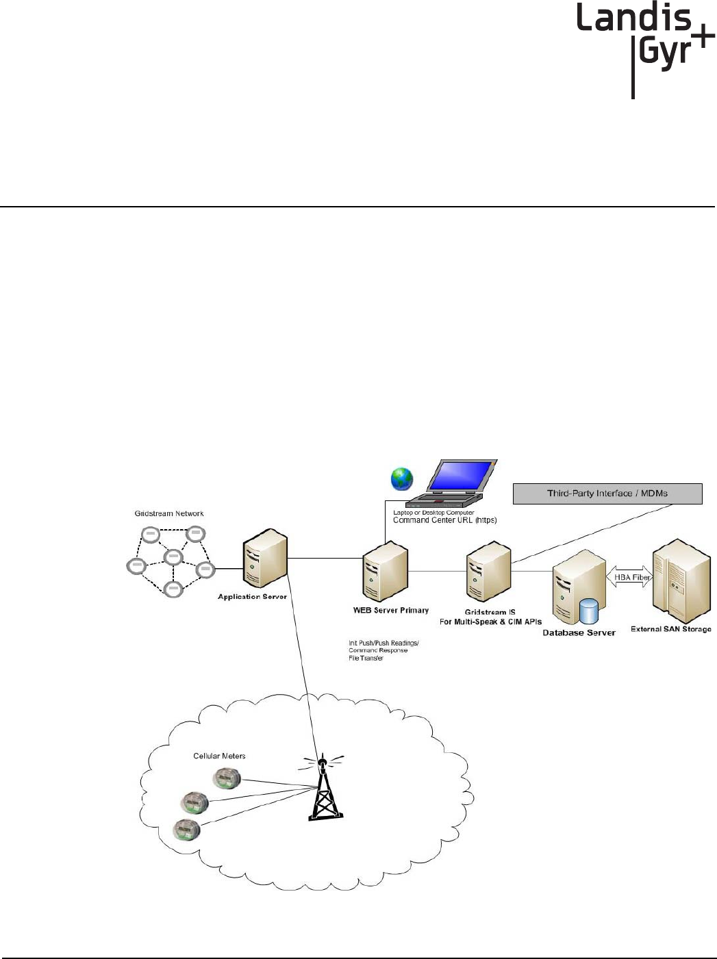
Landis+Gyr’s Gridstream Enhanced Cellular solution can expand network coverage for unique
metering applications, where other AMI communications may not be available.
The Landis+Gyr Cellular meters communicate point-to-point with Command Center’s M2M
(Machine to Machine) Adapter. The M2M Adapter is a component of Command Center that will
interface with the meter directly. This makes Cellular meters ideal for utilities with electric meters in
remote areas or areas where there is little to no infrastructure. The following diagram provides a high
level overview of a Gridstream Enhanced Cellular network with a Gridstream RF Network. The cel-
lular endpoints are unique in that the SIM card must be activated prior to deployment of the end-
points (See Chapter 4 “Deploying Endpoints”).
Figure 1 - 1. Cellular Network
Draft
Chapter 1 - Gridstream Enhanced Cellular Overview Landis+Gyr
8 98-1723 Rev AB User Guide
Point-to-Point Technology
Cellular meters communicate point to point with Gridstream Command Center. They do not commu-
nicate with other meters, routers, or collectors. Although cellular meters do not communicate
through a collector, Command Center will automatically assign a virtual collector to the meters. This
allows cellular technology to easily integrate into the existing Gridstream solution and simplifies
management of cellular meters.
Enhanced Cellular Endpoints perform Self Reads daily at midnight (by default). The reads will then
be sent to Command Center. Interval Data is pushed every four hours (by default). Cellular meters
can support interval data up to every fifteen minutes.
NOTE: Command Center must be installed/upgraded with Cellular functionality active. The Com-
mand Center Installer automatically installs cellular functionality unless the user has chosen to
exclude. See Landis+Gyr publication 98-1664, Command Center Installation Suite, for more informa-
tion on Gridstream Enhanced Cellular Installation.
NOTE: Meters must have custom attributes programmed at the time of manufacture. The cellular
endpoints are unique in that the SIM card must be activated prior to deployment of the endpoints.
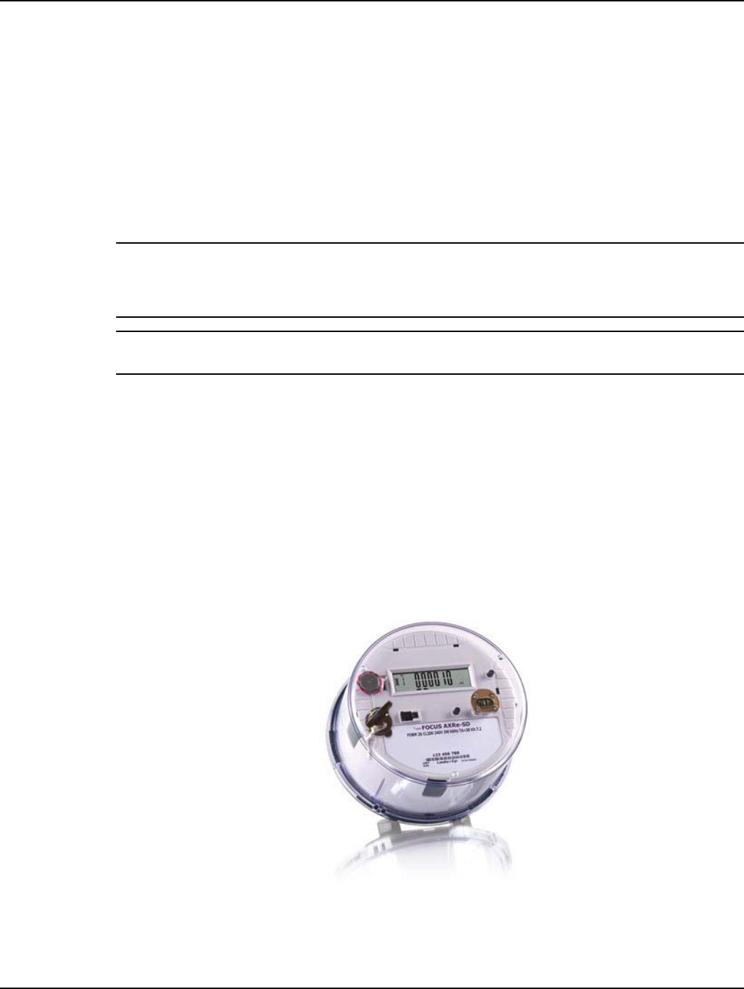
Endpoint Overview
The cellular communication module is not available as a stand alone product.
The endpoint assembly contains:
•Meter
•Gridstream Enhanced Cellular communication module
•Interior antenna for Cellular radio
•Built-in antenna for ZigBee
Figure 1 - 2. Landis+Gyr FOCUS AXe
Draft
Landis+Gyr Chapter 1 - Gridstream Enhanced Cellular Overview
User Guide 98-1723 Rev AB 9
Modem Information
The cellular meter contains a completely “under the cover” module that utilizes the GSM/GPRS/
EDGE/HSPA cellular technology. This allows cellular meters to be supported by multiple wireless
providers. (The initial release will support AT&T domestic US versions only.) Furthermore, the
AT&T module will be 3G capable, making it a viable solution for real time data transfer. (4G ver-
sions will be available in later releases.)
Figure 1 - 3. Cellular Module
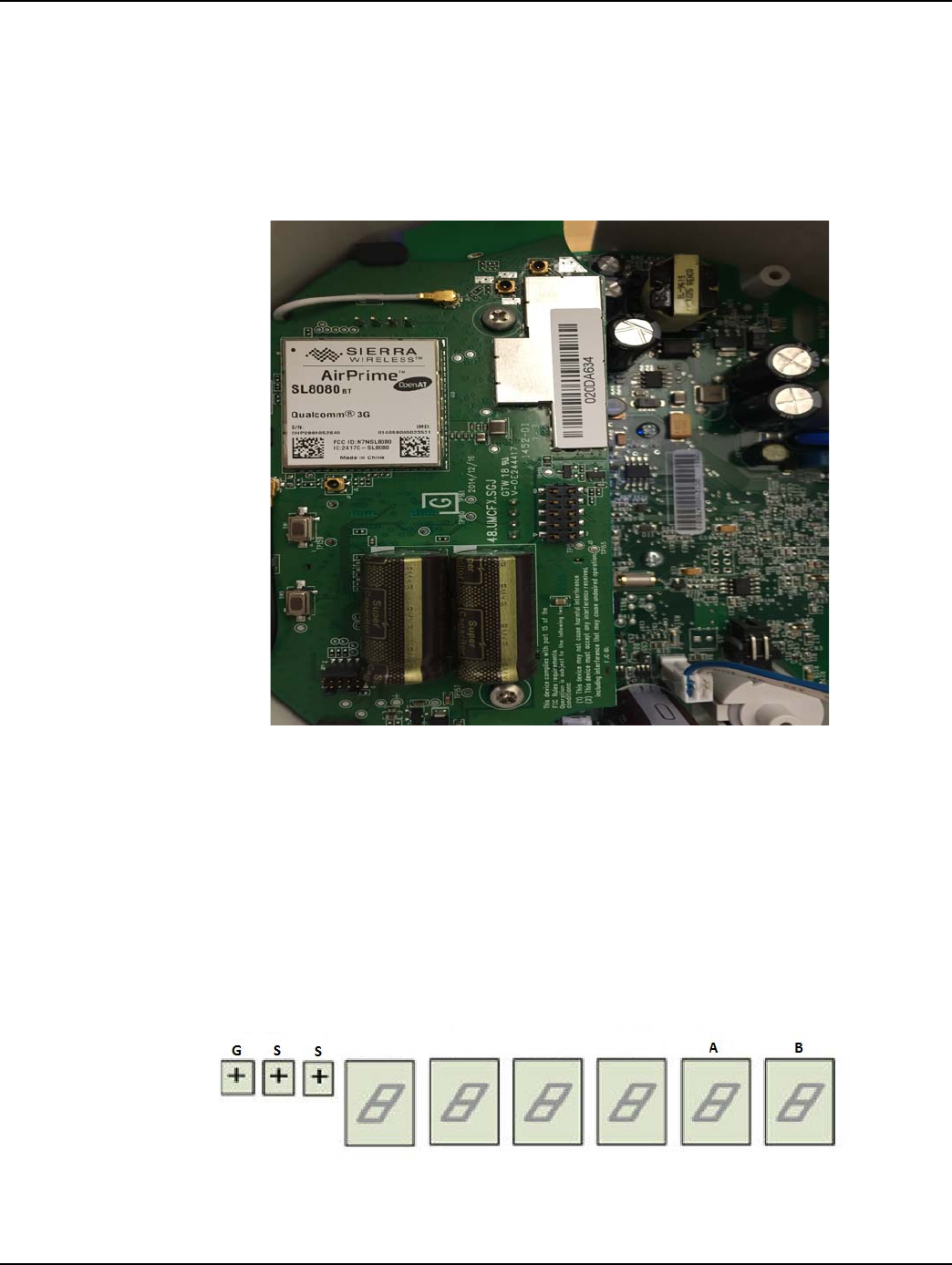
Meter Display
The FOCUS AXe is equipped with an LCD display. The display is configurable at the time of order-
ing or manually through the optic port and the use of 1132 prog/com. A key feature of the display is
the GSS Health Indicator screen. The GSS display screen will allow the user to easily identify any
issues with the device. This health check information can be used during field installation or trouble-
shooting activities to validate the radio status and provide key inputs to any communications issues
that may be encountered. The figure below illustrates the metrology display panel.
Figure 1 - 4. Metrology Display Panel
Draft
Chapter 1 - Gridstream Enhanced Cellular Overview Landis+Gyr
10 98-1723 Rev AB User Guide
The Meter Display will indicate "GSS" and all dashes if cellular communication has not been estab-
lished. Once cellular communication has been established, the last two indicators on the right side of
the display, we’ll refer to as A & B, will illustrate the following:
LAN ID
The LAN ID is a unique identifier for each Gridstream Enhanced Cellular endpoint. It is always dis-
played in hex. Landis+Gyr provides the LAN address. You cannot change the LAN ID of a radio.
The LAN ID (Endpoint Serial Number) will be matched to the Meter ID through a Meter Manufac-
turer File (MMF). The MMF will be provided to you by Landis+Gyr with your meter purchase.
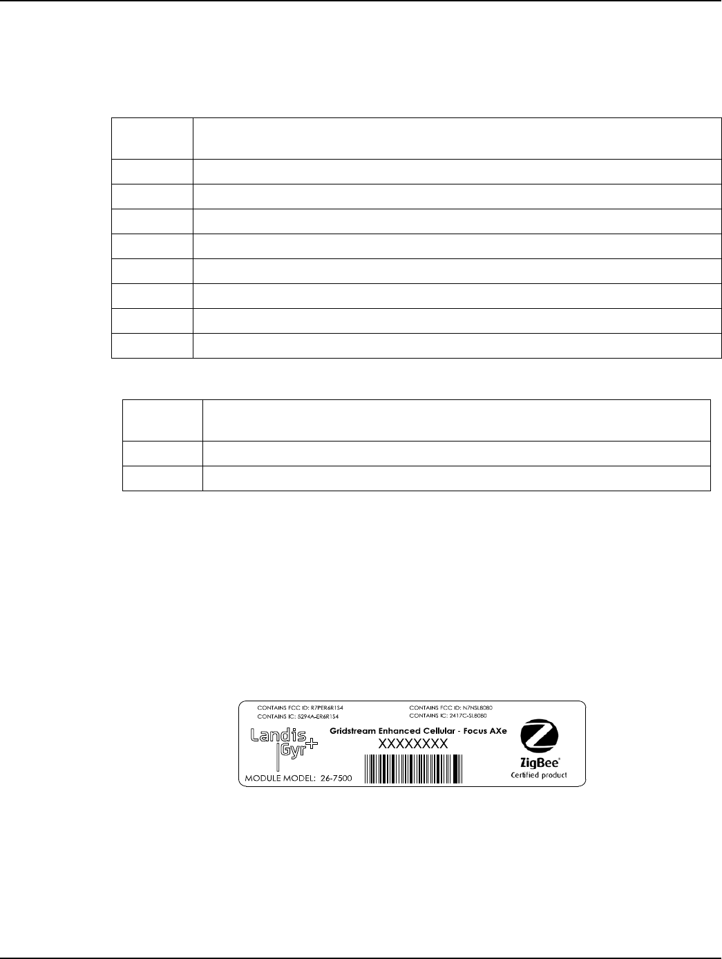
Labels
The endpoint includes the following labels:
Figure 1 - 5. Label Identification
A. Landis+Gyr Product ID (printed)
B. Landis+Gyr LAN ID, includes programmed module part number (printed and barcoded)
Table 1-1. Communication Hardware Status
Status Slot
ADescription
0 No communication failures to report
1 Cellular connection not established
2 Communication with ZigBee module failed
3 Cellular connection not established + communication with ZigBee module failed
4 Communication to NTP server not established
5 Cellular connection not established + Communication to NTP server not established
6 Communication to NTP server not established + Communication with ZigBee module failed
7 Combination of codes 4 + 2 + 1
Table 1-2. Head End Communication Status
Status
Slot B Description
0 Registered with Command Center
1 Has not registered with Command Center

Draft
Landis+Gyr Chapter 1 - Gridstream Enhanced Cellular Overview
User Guide 98-1723 Rev AB 11
ZigBee Support
The Gridstream Enhanced Cellular communication module supports an integrated ZigBee system on
the chip. This enables the endpoint to communicate via Smart Energy Profile with other ZigBee
enabled devices.
Retrieving Data
The endpoint is capable of delivering data via an On Request Read (ORR) or autonomously (period-
ically reported).
Availability of the following features depends on meter configuration. On Request Reads (ORR)
available with this endpoint are:
•Register Data (Standard Table 23) which includes consumption, demand and TOU values
•Load Profile or Interval Data. Multiple Load Profile channels will be available for meters
that support it (Standard Table 64 FOCUS AXe)
•Revenue Integrity Services which includes instantaneous measurements related to line
voltage, current and phase angle
Availability of the following features depends on meter configuration. Options for periodic reported
data with this module include:
•Register Data & Status Flags (Standard Tables 23 & 3) which includes consumption,
demand, TOU values and meter status
•Load Profile or Interval Data & Status Flags (Standard Tables 64 & 3) which includes
interval data and meter status
Demand Reset
When the Command Center Host delivers a Demand Reset command, the communication module
passes the command to the meter, which performs the Demand Reset on the meter. The endpoint
then passes the previous demand data captured by the meter (Standard Table 25) to the Host for pro-
cessing. Scheduling the demand resets may be performed through the Command Center Host. See
the chapter on Demand Resets in this manual for further instructions.
Power Outage/Restoration
When an outage greater than 30 seconds occurs, the meter uses an early power failure signal to alert
the communication module to disconnect from the meter's power immediately. The communication
module saves critical module data to non-volatile memory and creates and sends a power outage
message. This message includes the following information:
•LAN ID
•Outage timestamp
•Outage count

Draft
Chapter 1 - Gridstream Enhanced Cellular Overview Landis+Gyr
12 98-1723 Rev AB User Guide
When power is restored, the communication module reconnects with the network at a randomly
delayed time up to 30 minutes. This is to ensure that too many devices do not connect to the cell
tower simultaneously. With network communications restored, the communication module sends a
power restoration message that includes details such as:
•LAN ID
•Power Restoration Timestamp
•Power Outage Timestamp
•Sustained Outage Count
The communication module stores a history of power outage and restoration event pairs in the event
log. The user may request this data using Command Center.
Downloading Firmware
At times it may be necessary to perform firmware upgrades to enhance or enable functionality. The
communication module, meter, and ZigBee firmwares may all be upgraded remotely over the air
from Command Center. Command Center will allow the user to perform firmware updates to indi-
vidual devices. However, updates may also be group addressed, making it easier to upgrade several
devices at once. When the endpoint completely receives the new code, it will reboot. After powering
back up, the device will load the new firmware and normal operation will resume. The Firmware
download can be scheduled in Command Center or done immediately.
Encrypting Data
The Gridstream Cellular network currently supports Standard and Advanced security. For more
information on Command Center Security, please refer to the Landis+Gyr Security Administrator’s
Guide: publication 98-1035.
SIM Activation
The endpoint SIM must be active in order for the endpoint to join AT&T’s wireless network and reg-
ister with Command Center.
NOTE: Meters must have custom attributes programmed at the time of manufacture. The cellular
endpoints are unique in that the SIM card must be activated prior to deployment of the endpoints.
Auto-Registration
Once powered up, the modules will begin the auto-registration process. This will allow installers to
walk away and have the meters complete the process on their own. For more information on auto-
registration for cellular meters, please refer to“Auto-Registration” on page 26.

Draft
Landis+Gyr Chapter 1 - Gridstream Enhanced Cellular Overview
User Guide 98-1723 Rev AB 13
FCC and Industry Canada Compliance
FCC Class B
This device complies with Part 15 of the FCC rules. Operation is subject to the following two condi-
tions:
1. This device may not cause harmful interference, and
2. This device must accept any interference received, including interference that may cause
undesired operation.
This equipment has been tested and found to comply with the limits for a Class B digital device, pur-
suant to Part 15 of the FCC Rules. These limits are designed to provide reasonable protection against
harmful interference in a residential installation. This equipment generates, uses, and can radiate radio
frequency energy and, if not installed and used in accordance with the Instructions, may cause harmful
interference to radio communications. However, there is no guarantee that interference will not occur
in a particular installation. If this equipment does cause harmful interference to radio or television re-
ception, which can be determined by turning the equipment off and on, the user is encouraged to try
to correct the interference by one or more of the following measures:
•Reorient or relocate the receiving antenna.
•Increase the separation between the equipment and receiver.
•Consult Landis+Gyr or an experienced radio technician for help
UWARNING: Changes or modifications to this device not expressly approved by Landis+Gyr
could void the user’s authority to operate the equipment.
RF Exposure
This equipment complies with FCC and ISED radiation exposure limits set forth for an
uncontrolled environ-ment. This equipment should be installed and operated with minimum
distance 20cm between the radiator and your body. This transmitter must not be co-located or
operating in conjunction with any other antenna or transmitter.
Cet équipement est conforme aux limites FCC et ISED d'exposition aux radiations définies pour un
envi-ronnement non contrôlé. Cet équipement doit être installé et utilisé à une distance minimale de
20cm entre le radiateur et votre corps. Cet émetteur ne doit pas être co-implantés ou exploités en
con-jonction avec une autre antenne ou émetteur.
Industry Canada
This device complies with Industry Canada licence-exempt RSS standard(s). Operation is subject to
the following two conditions: (1) this device may not cause interference, and (2) this device must
accept any interference, including interference that may cause undesired operation of the device.
Under Industry Canada regulations, this radio transmitter may only operate using an antenna of a
type and maximum (or lesser) gain approved for the transmitter by Industry Canada. To reduce
potential radio interference to other users, the antenna type and its gain should be so chosen that the
equivalent isotropically radiated power (e.i.r.p.) is not more than that necessary for successful com-
munication.
Draft
Chapter 1 - Gridstream Enhanced Cellular Overview Landis+Gyr
14 98-1723 Rev AB User Guide
Le présent appareil est conforme aux CNR d'Industrie Canada applicables aux appareils radio
exempts de licence. L'exploitation est autorisée aux deux conditions suivantes : (1) l'appareil ne doit
pas produire de brouillage, et (2) l'utilisateur de l'appareil doit accepter tout brouillage radioélec-
trique subi, même si le brouillage est susceptible d'en compromettre le fonctionnement.
Conformément à la réglementation d'Industrie Canada, le présent émetteur radio peut fonctionner
avec une antenne d'un type et d'un gain maximal (ou inférieur) approuvé pour l'émetteur par Industrie
Canada. Dans le but de réduire les risques de brouillage radioélectrique à l'intention des autres utili-
sateurs, il faut choisir le type d'antenne et son gain de sorte que la puissance isotrope rayonnée équiv-
alente (p.i.r.e.) ne dépasse pas l'intensité nécessaire à l'établissement d'une communication
satisfaisante.
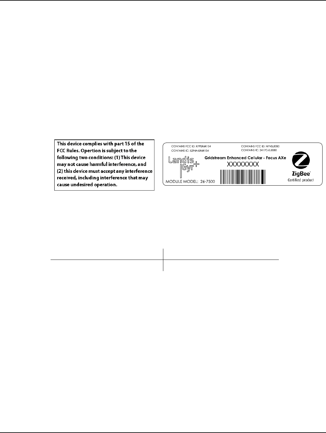
Labels
The endpoint includes the following labels:
Figure 1 - 6. Label Identification
Host FCC Label Requirements
The host label(s) must be clearly visible after the device is installed, and display the module FCC ID
in the following format:
The following statement must also be clearly visible:
This device complies with part 15 of the FCC Rules. Operation is subject to the following two condi-
tions:
(1) This device may not cause harmful interference, and
(2) this device must accept any interference received, including interference that may cause unde-
sired operation.
Documentation Feedback
To provide feedback about this documentation, contact the Technical Documentation team at ustech-
nicaldocumentation@landisgyr.com.
Contains FCC ID: R7PER6R1S4 Contains FCC ID: N7NSL8080
Contains IC: 5294A-ER6R1S4 Contains IC: 2417C-SL8080

Draft
User Guide 98-1723 Rev AB 15
2
Setting Up Command Center
Setting up Command Center
The following section describes system setup and functionality associated with Gridstream
Enhanced Cellular electric meters.
Prerequisites to Enable Gridstream Enhanced Cellular Meter
Functionality
There are multiple prerequisites to enable cellular meter functionality.
1. Install/Upgrade Command Center to version 6.4 or higher version with the M2M Adapter
installed.
2. In Command Center, activate Gridstream Enhanced Cellular Command Center license.
Command Center Installation
Command Center must be installed/upgraded with Cellular functionality active. The Command Cen-
ter Installer automatically installs cellular functionality unless the user has chosen to exclude. See
Landis+Gyr publication 98-1664, Command Center Installation Suite, for more information on
Gridstream Enhanced Cellular Installation.
Gridstream Cellular License
A license agreement governs the use of Command Center software. The licensing program allows
customers to purchase additional software functionality, such as Cellular.
A Gridstream Enhanced Cellular Command Center license is required to enable cellular meter
functionality in Command Center, and is required for cellular meter auto-registration.

Draft
Chapter 2 - Setting Up Command Center Landis+Gyr
16 98-1723 Rev AB User Guide
Figure 2 - 1. Command Center License
Following is the procedure to activate a Command Center License:
1. From Command Center Home, click Setup > Activate License. A list of currently licensed
software will display.
2. To activate additional software, enter the Activation Code provided by Sales Support in the text
box.
...or...
Click the Browse button to navigate to the location of the license file supplied by Sales Support.
•Double-click the license file name to add the file to the license file text box.
3. Click the Activate button to activate the license.
After successful activation, the Activate License screen will refresh to confirm the items that have
been licensed.
Process Settings
The Process Settings function allows the user to control how often several Central Server processes
occur. The processes are inherent to the normal operation of the Central Server and are rarely modi-
fied.
From Command Center home, select Setup > Process Settings. The Process Settings window will
appear.
Draft
Landis+Gyr Chapter 2 - Setting Up Command Center
User Guide 98-1723 Rev AB 17
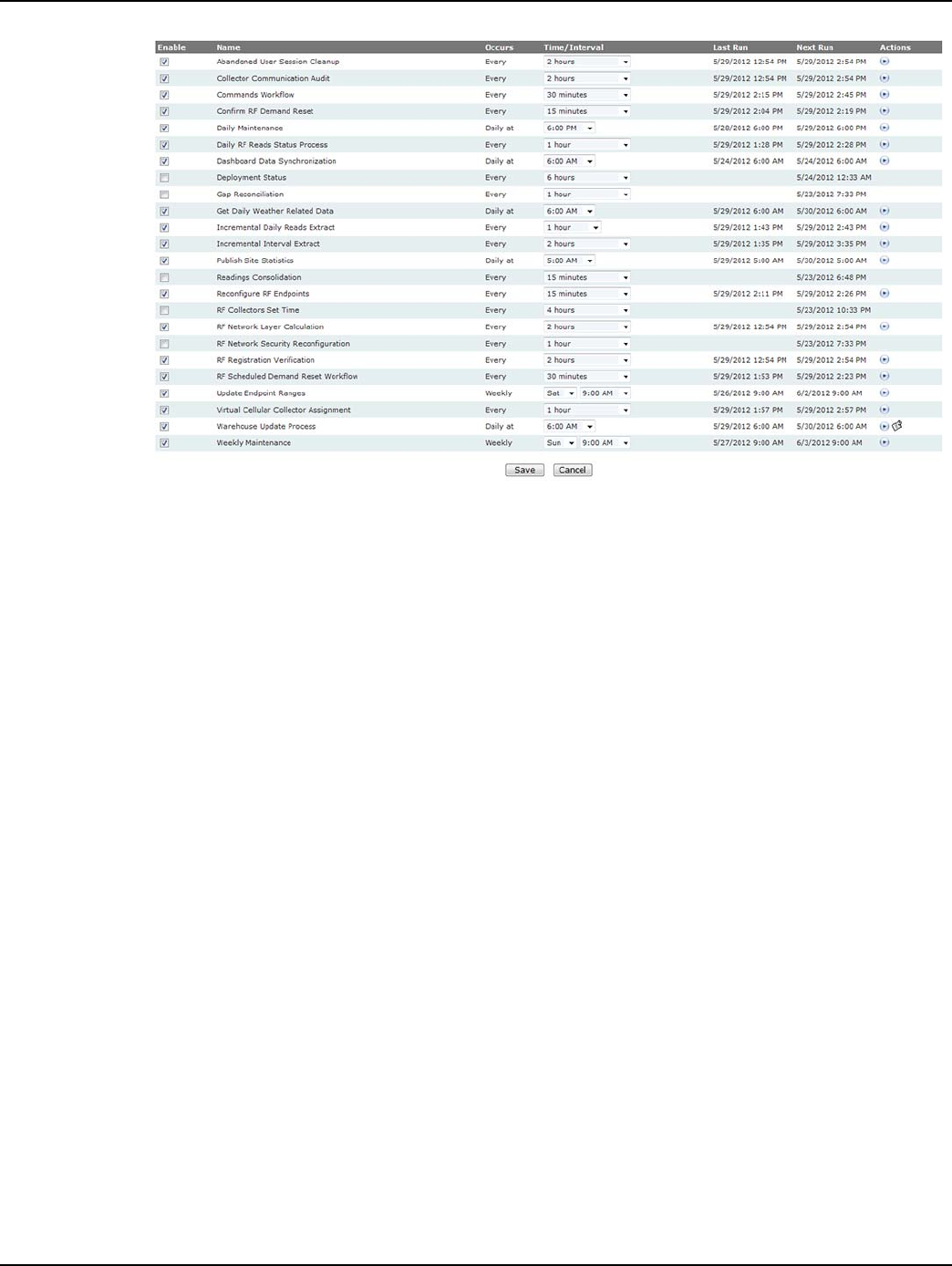
Figure 2 - 2. Process Settings
The Process Settings column heading include the following functions:
• Enable. Select the check-box for the appropriate process to enable that function. Clear the
check-box to disable the function.
•Name. This column displays each function.
•Occurs. This column displays the interval at which each function runs.
• Time/Interval. This column allows the user to select a time for the appropriate function
from the corresponding drop-down menu.
•Last Run. This column displays the last date and time that process was run.
•Next Run. This column displays the date and time of the next scheduled process.
•Actions. This column displays a History icon in the Warehouse Update Process row. Click
the History link to view the Process History (last 30 days) screen. IF there are any failed
links in the Status column, click the link to view the reason why the task did not run. The
Action column also displays a Run Now icon in most rows. Click the icon to immediately
run the desired process.
The following process settings on the page apply to cellular meters:
• Daily RF Reads Status Process: When readings are received from cellular meters, this
process will update the information displayed on the Daily Reads Status report. From the
drop down menu, select how frequently the information on the Daily Reads Status report is
updated.
• Dashboard Data Synchronization: Cellular meters will be included in statistics on the
dashboards. This process can be used to keep the dashboard “in sync”. It is not enabled by
default and will typically be used to process all the data aggregations for the dashboard by
force. The default selection is daily at 6 AM.
• Deployment Status: Cellular meters will be included in the statistics on the deployment
status report. This process updates the deployment status report. The default schedule is

Draft
Chapter 2 - Setting Up Command Center Landis+Gyr
18 98-1723 Rev AB User Guide
every 6 hours, however, this process may be run more frequently during times of heavy
deployment.
• Event Gap Reconciliation: Performs gap reconciliations for events.
• Event Gap Reconciliation Retry: Retries event gap reconciliation requests, where no
response has been received.
• Incremental Daily Reads Extract: When self read data has been received from cellular
meters, this process will generate the incremental daily reads extract files. This process
established the frequency at which the incremental daily reads extract will be performed.
• Incremental Interval Extract: When interval data readings are received from cellular
meters, this process will generate the incremental interval data extract files. This process
established the frequency at which the incremental daily reads extract will be performed.
• Gap Reconciliation: A process that requests gap data from the network.
• Gap Reconciliation Retry: This process setting allows the user to establish whether gaps
retrieval will be re-attempted, and if so, how frequently the process will run.
• RF Network Security Reconfiguration: The RF Network Security Reconfiguration
process checks for endpoints that require security configuration updates, such as
transmission of the network key. This process also enables the retry of security configuration
commands until all attempts have been exhausted.
• Reconfigure RF Endpoints: Select the desired time from the drop down list box. The
Reconfigure Endpoint process is the process in which Command Center communicates with
the collectors as to which endpoints need to be re-configured. The reconfigure endpoint
settings determines how frequently the system will send commands directing
reconfiguration to the endpoints.
NOTE: If changes have been made to the process settings, click Save to apply the changes.

Draft
User Guide 98-1723 Rev AB 19
3
Meter Ordering and
Customization
Overview
1. Customer needs to provide Landis+Gyr with an IP address for Command Center (M2M
Adapter), IP address for the NTP server, GMT offset for meters, and the Network ID of
Command Center at the time they order meters. Modules will be preprogrammed with the
customer supplied information and the Cellular IP addresses for auto-registration to occur.
2. Customer will need to setup and activate a cellular account with the carrier prior to deploying
meters. (Hosted customers may have this done by Landis+Gyr) Activating the account ensures
that the cellular IP addresses will be able to communicate to the Cellular Network Access Point
Name (APN). If the account has not been activated, auto-registration will not occur.
Draft

Draft
User Guide 98-1723 Rev AB 21
4
Deploying Endpoints
SIM Activation
The endpoint SIM must be active in order for the endpoint to join AT&T’s wireless network and reg-
ister with Command Center.
NOTE: Meters must have custom attributes programmed at the time of manufacture. The cellular
endpoints are unique in that the SIM card must be activated prior to deployment of the endpoints.
Auto-Registration
New meters can be installed with no special tools required. The device is plug and play; this means
that the installer can plug the meter in, and walk away.
When the meter is powered up it will perform the following:
• Transmit Init Push packet. The endpoint will send an Init Push Packet about 1-2 minutes
after it acquires a network, then every 12 hours until it receives the Confirm Registration
command.
• Transmit Registration packet. The registration packet identifies the device on the network.
Once this packet is received by Command Center, the endpoint will transition to Discovered
status.
The M2M Adapter is responsible for generating and transmitting the registration packet as
soon as it receives an Init Push Packet from the endpoint.
The Init Push packet contains configuration information, that allows Command Center to understand
the configuration of the meter. This information will vary dependent on the configuration of the
meter, but generally includes:
•Reporting for Interval Data
•Reporting for Register Data
•Time Synchronization parameters
•GMT offset
•Meter Configuration information
Draft
Chapter 4 - Deploying Endpoints Landis+Gyr
22 98-1723 Rev AB User Guide
Adding Endpoints
Meter Manufacturer File Import Process
A Meter Manufacturer File is provided to the utility. The file contains meter number/serial number
combinations. The Meter Manufacturer File must be imported into Command Center before meters
are deployed.
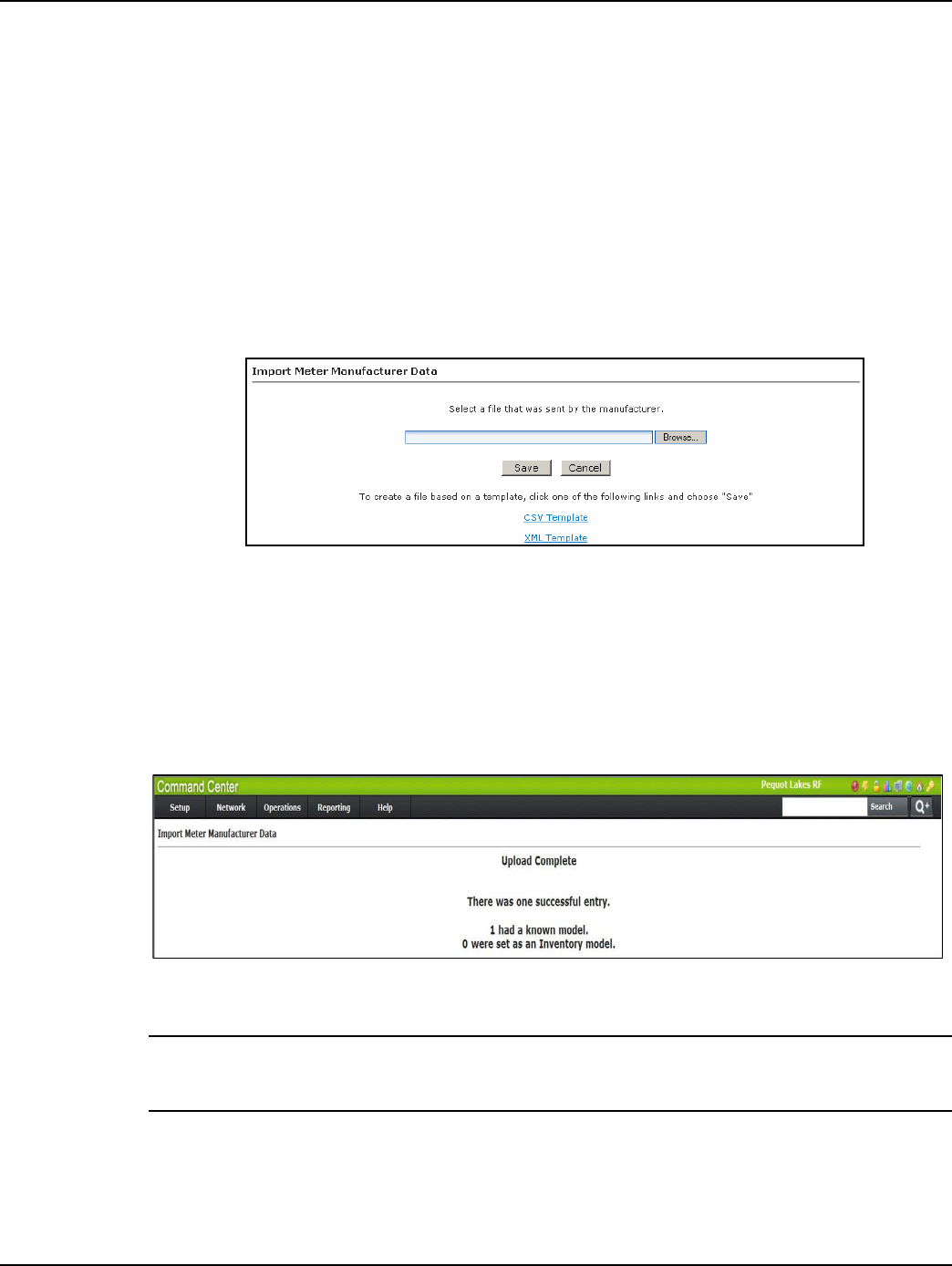
The Meter Manufacturer Data screen allows the user to import an XML or CSV file supplied by the
meter manufacturer so the utility does not have to key in meters and endpoints by hand.
1. Click Operations > Import > Meter Manufacturer Data to display the Import Meter
Manufacturer Data screen.
Figure 4 - 1. Import Meter Manufacturer Data
2. Click the Browse button to navigate to, and select, a file that was sent by the meter
manufacturer.
3. Click the Save button to import the file into the database.
The Meter Manufacturer Data Import (Upload Complete) window will appear displaying the Error
Summary (if applicable) and Successful Entries.
Figure 4 - 2. Upload Complete Window
NOTE: NOTE: Any entries under Error Summary will be red text. The usual reason for an entry under
Errors is that the endpoint already exists in the system. If file parsing errors or other file-related errors
occur, contact the meter manufacturer that supplied the file.
4. Successful entries will be added to inventory and will be displayed on the dashboard as
Inventory status.
Draft
Landis+Gyr Chapter 4 - Deploying Endpoints
User Guide 98-1723 Rev AB 23
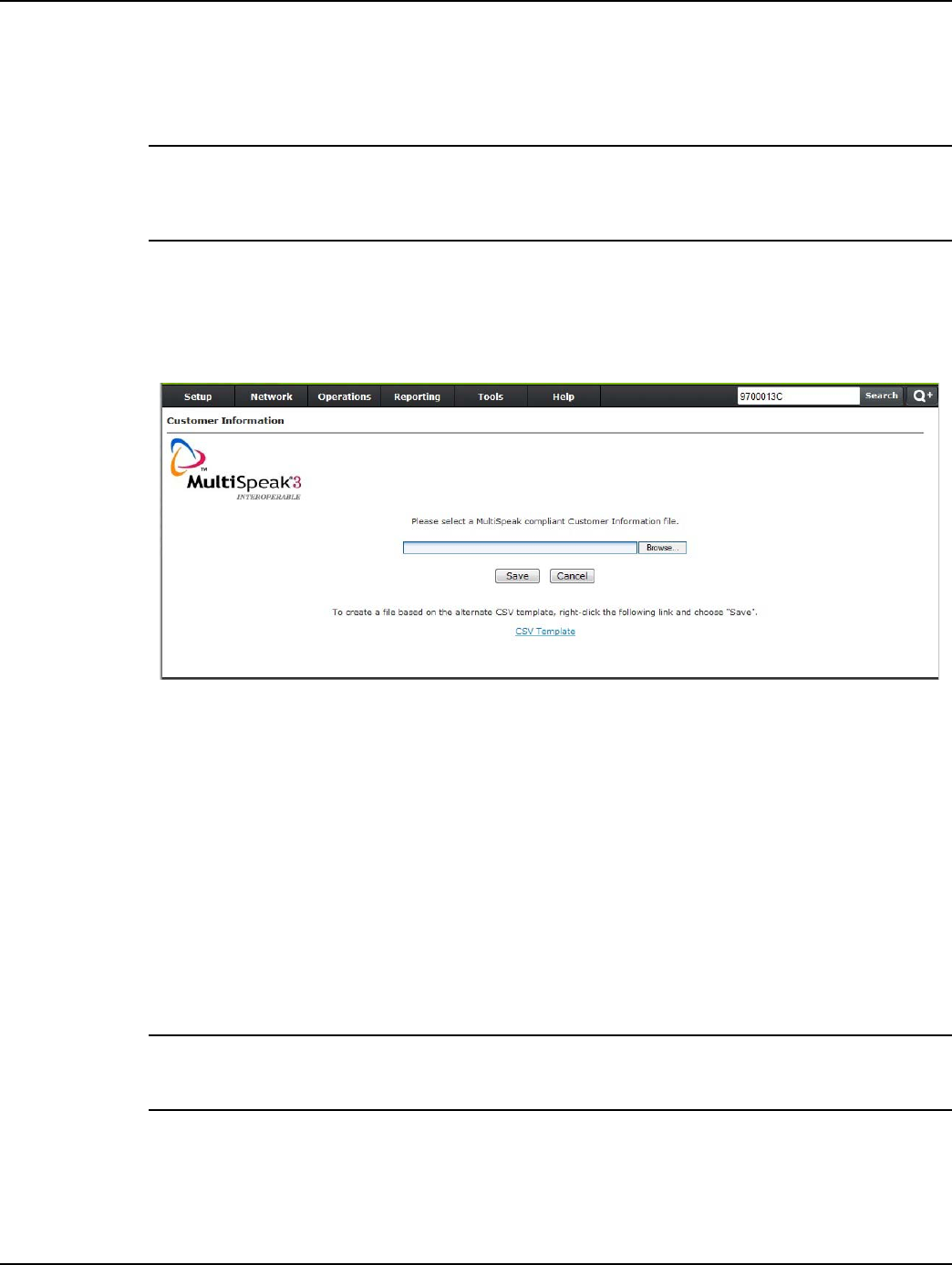
Customer Information File
Customer information must be associated with the Cellular meters via a flat file import, through inte-
gration services, or by manually entering the information into Command Center.
NOTE: A Customer Information File will be provided to the customer with the Meter Manufacturer
File. The CIF is a required file, because it contains the Integrated Circuit Card Identifier (ICCID)
which is associated with the meter number. This value will be needed in order to activate the cellular
account, so that auto-registration can occur. The ICCID will populate the Custom 1 field in the CIF.
Following is the procedure for associating customer information with cellular meter modules
through a flat file import:
1. Click Operations > Import > Customer Information. The Customer Information window will
open, shown in the following figure.
Figure 4 - 3. Customer Information
2. Enter the path to the file that contains the meter modules to be archived, or click the Browse
button to browse to the file location.
3. Click Save to import the file. Customer data provided in the import file will now be associated
with the water modules.
The .csv template hyperlink will open a template which can be used for creating the file.
Import Installation File
After the meter manufacturer file has been imported, the installation file can be imported. The instal-
lation file includes information about the date and time of the installation, as well as latitude and lon-
gitude information for the Center system map.
NOTE: NOTE: Importing installation data is not a requirement, however some Command Center
deployment tracking and troubleshooting reports will be affected if installation date/time, latitude and
longitude are not populated in the Command Center database.

Draft
Chapter 4 - Deploying Endpoints Landis+Gyr
24 98-1723 Rev AB User Guide
The information imported via the Installation File is shown in Table 4-1, “Import Installation File.”
An asterisk indicates a required field.
NOTE: NOTE: Required fields are UserID, Installed Date, InstalledTime, InstalledMeterNo, and
InstalledEndpointSN. If these fields are not populated, the file will not be processed. Service Loca-
tion is required if the Latitude and Longitude fields are populated. Command Center will ignore the
latitude and longitude values if Service Location is not provided.
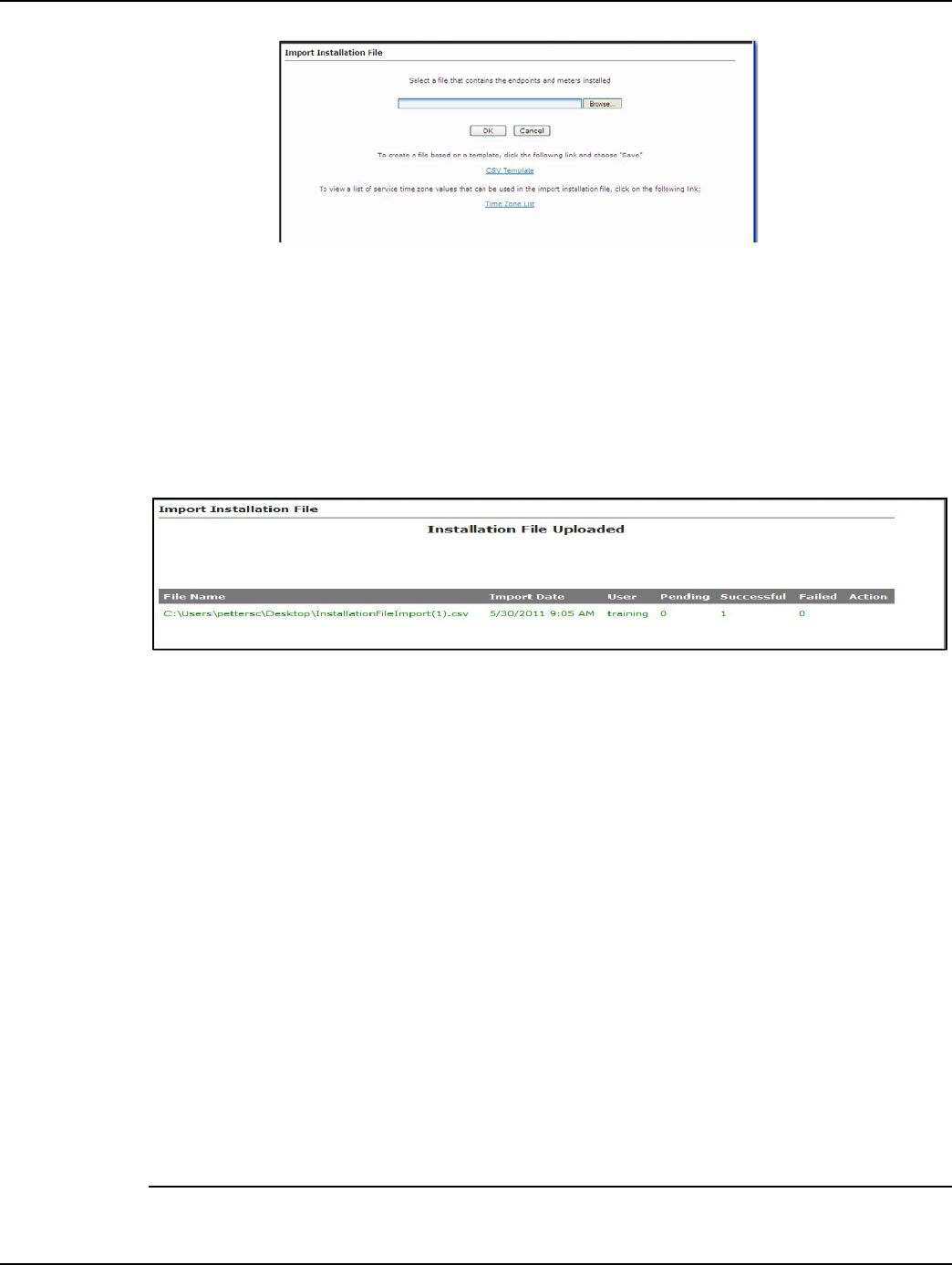
Following is the procedure for importing the Installation File.
1. Click Operations > Import > Import Installation File. The Import Installation File window
will open, shown in Figure 4 - 4.
Table 4-1. Import Installation File
Data Format Format/Description
User ID* AlphaNum (30) Login assigned by the utility for the installer. Utility may
elect to use “1” for System usage.
Installation Date*
Date
MM/DD/YYYY
12/26/2009
Actual date the meter was installed. This date is used in
various Command Center reports to track deployment
statistics.
Installation Time*
Time HHMM AM/
PM
11 :12 A M
Actual time the meter was installed. This date is used in
various Command Center Reports to track deployment
statistics.
Change Out meter number AlphaNum (20)
The meter being replaced with a new meter. Meter
change out information is displayed in the notes section
of the endpoint information screen.
Change Out meter kWh AlphaNum (20)
The kWh reading on the meter being replaced. Meter
change out kWh information is displayed in the notes
section of the endpoint information screen. Variable
Character.
Installed Meter Number* AlphaNum (20)
Meter number of the new meter being installed. This
meter must exist in Command Center prior to importing
the Import Installation File. Must parse to Decimal
format.
Installed Endpoint Serial
Number* Decimal (9)
The serial number of the new meter being installed.
Note: Endpoint serial numbers must be converted from
Hex to Decimal.
Installed Meter kWh Decimal (9) Initial reading of the new meter.
Service Latitude Decimal (12,8) GPS latitude.
Service Longitude Decimal (12,8) GPS longitude.
Service Location AlphaNum (100) Meter service location.
Service Time Zone See formatting
below
The service time zone may be entered to specify the
correct time zone for the service location. This field is
required for those utilities where the distribution spans
time zones. The GMT offset will be programmed into the
module at time of manufacturing.
Draft
Landis+Gyr Chapter 4 - Deploying Endpoints
User Guide 98-1723 Rev AB 25
Figure 4 - 4. Import Installation File
The Import Installation File window provides a .csv template link, that may be used to create
the IIF.
2. Type the file location path into the text box
...or...
Click the Browse button to navigate to the appropriate file.
3. Click OK to upload the file.
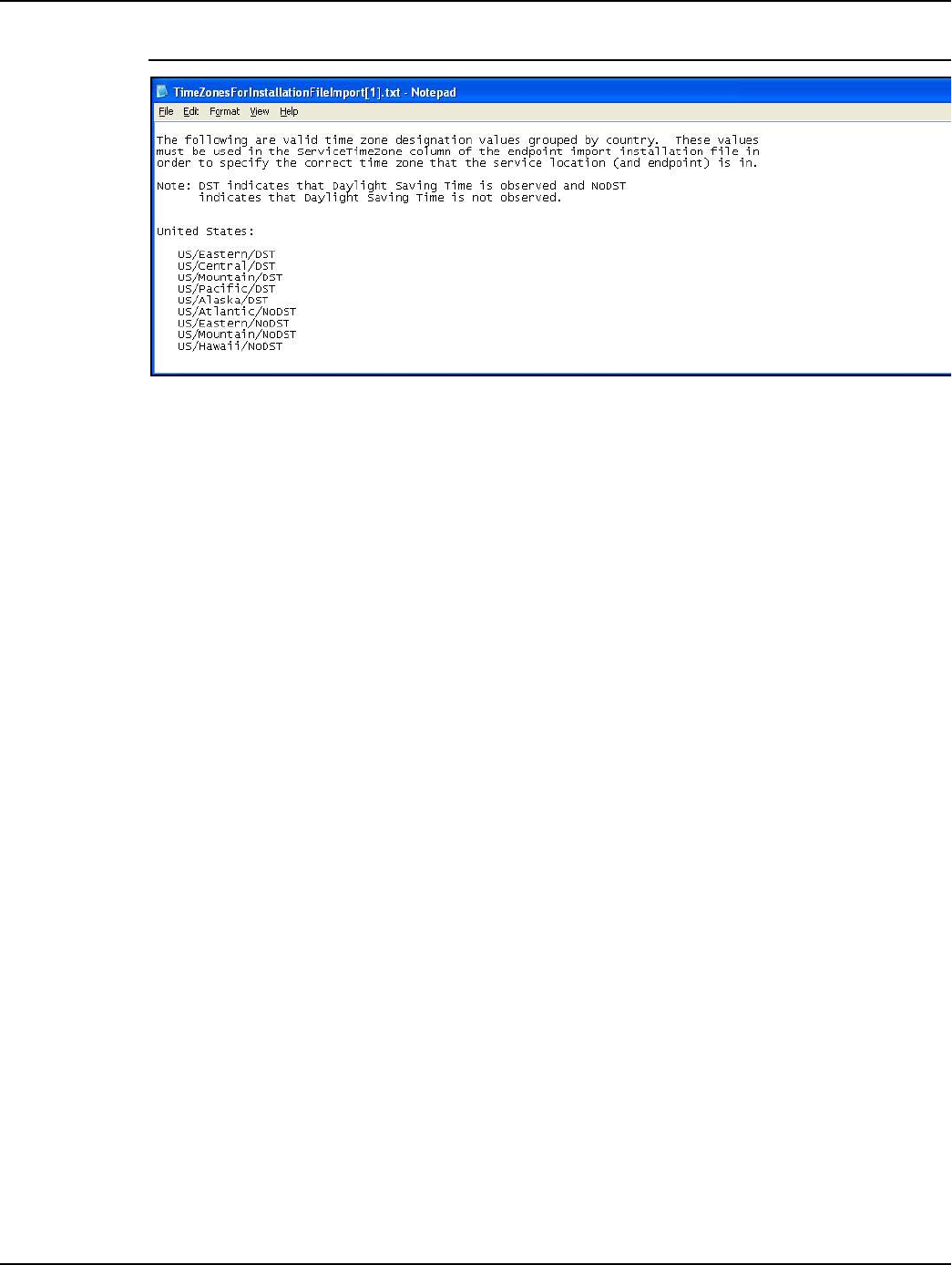
Figure 4 - 5. Import Installation File
If an error occurs in the import of the Installation File, results will be displayed immediately in the
browser.
The following status values may be displayed:
•Pending: This is an unused status value and not applicable.
•Pending Init Push: The modules will transition to Normal when the InitPush is received.
•Successful: The Init Push has been received from the modules, and they are in
Discovered state.
•Failed: The Import Installation file failed for some modules.
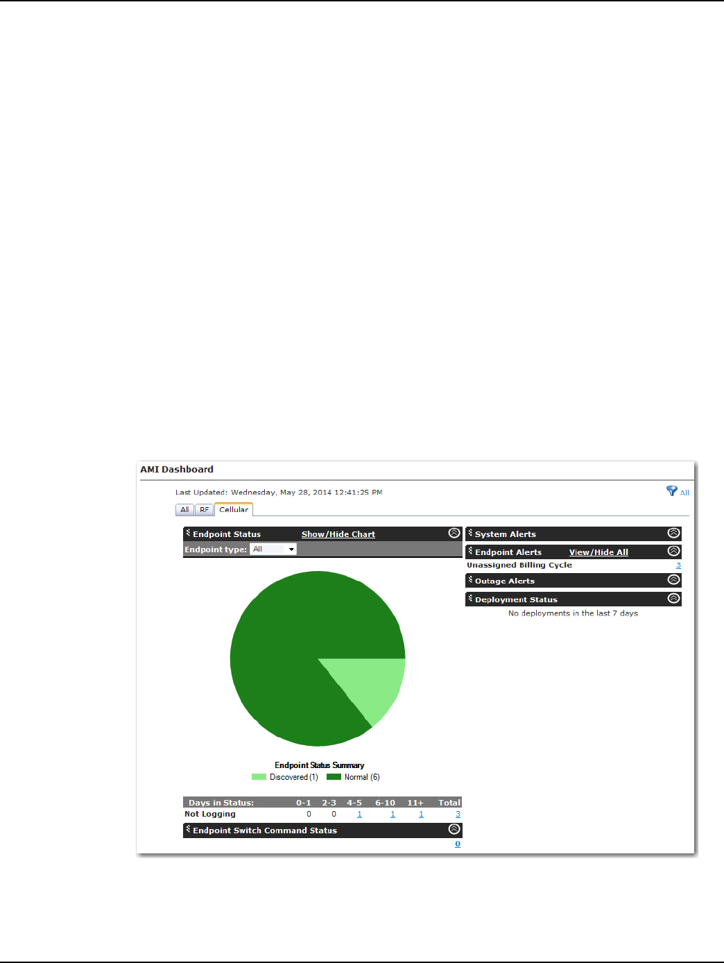
Time Zone
In order for a module to time stamp events, it must be programmed with appropriate time zone set-
tings. If provided with time zone data, Command Center will issue commands that indicate the time
zone in which the meter is installed and whether Daylight Savings Time (DST) is observed. For
those utilities that span multiple time zones, the installer should include the time zone in the Installa-
tion File.
To make it easy for installers to specify a time zone, the Time Zone List link will open a document
that displays a list of valid time zone designations by country, shown in Figure 4 - 6.
NOTE: The cellular modules will have the time zone programmed at the time of manufacturing. It is
Draft
Chapter 4 - Deploying Endpoints Landis+Gyr
26 98-1723 Rev AB User Guide
possible, however not preferred, to order batches of meters with separate time zones.
Figure 4 - 6. Time Zones
Auto-Registration
After importing the necessary files and activating the SIM card with AT&T, installers may deploy
meters in the field. Once powered up, the modules will begin the auto-registration process. For auto-
registration to be successful, the following steps need to be performed:
1. A Meter Manufacturer File (MMF) will be provided to the customer with their meter order. This
must be imported into Command Center prior to deployment for auto-registration to occur.
2. A Customer Information File (CIF) will also be provided to the customer with their meter order.
This file will contain the Integrated Circuit Card Identifier (ICCID) associated with the meter
number. These numbers need to be imported into Command Center before auto-registration can
complete.
3. An Import Installation File (IIF) may be used to import other installation details such as:
Installation Date, Installation Time, Lat/Lon coordinates, and service locations. This is an
optional file and is not required for auto-registration to complete.
With the Command Center setup, MMF and CIF files uploaded, and SIM activation complete, the
installer may deploy the meter.
•When the meter first powers up, it will attempt to connect to the nearest cell tower and
acquire time from the NTP server.
•When the module has time, it will generate and send an Init Push through the APN to the
M2M adapter.
•The M2M adapter will generate a virtual collector in Command Center. (The ID of the
collector will be a location area code or the cell tower ID.)
•The M2M adapter will then generate a registration packet, associating the module to that
collector. At this point the module will transition to Discovered in Command Center.
•The Init Push will then be sent to Command Center from the M2M adapter.
•Command Center will respond immediately to the Init Push by sending out a Confirm
Registration command to the endpoint.
•A response to the Confirm Registration command will transition the meter to Normal.
Draft
Landis+Gyr Chapter 4 - Deploying Endpoints
User Guide 98-1723 Rev AB 27
•If the endpoint configuration sent in with the Init Push is not recognized, Command Center
will transition it to Configure.
•A Reconfiguration command will be sent from Command Center to set the endpoint
configuration group. (If the meter is ZigBee enabled, a HAN Initialization command will be
sent, also setting it to Configure.)
•A response to the reconfiguration command (or HAN Initialization) will transition the
endpoint to Normal in Command Center.
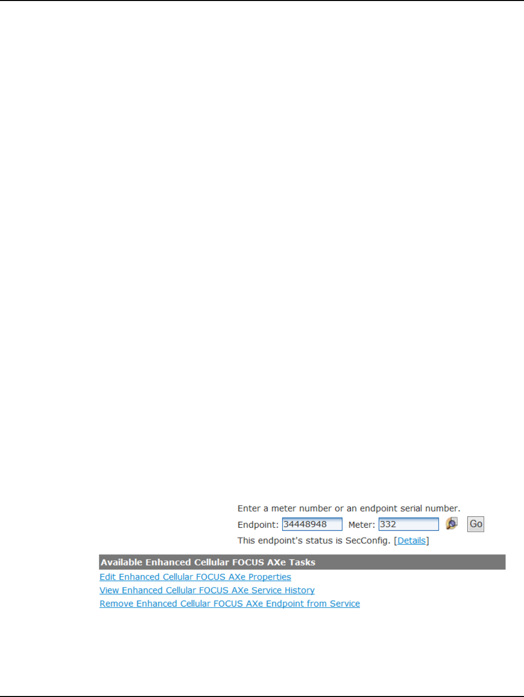
Monitoring the Dashboard
The Dashboard provides notification of system events and the status of system processes in a timely
manner without user interaction. The dashboard should be monitored by the administrator on a regu-
lar basis, throughout the day.
Click Network > AMI Dashboard. The dashboard will open.
The dashboard will show filtering options depending on the technologies that the utility is licensed
for. Selecting the filtering tabs will display just the devices associated with that technology.
•ALL. Select All to display every endpoint in the system.
•RF. Select RF to display only RF endpoints in the system.
• Cellular. Select Cellular to display only Cellular endpoints in the system.
Figure 4 - 7. AMI Dashboard - Cellular Tab

Draft
Chapter 4 - Deploying Endpoints Landis+Gyr
28 98-1723 Rev AB User Guide
Endpoint Status
The Endpoint Switch Command Status section will display all endpoints in the system and their
associated status. The endpoint status may be filtered by endpoint type. Available endpoint types
depend on the type of meters for which Command Center has been licensed.
Cellular meters support the following endpoint status values:
•Inventory: The cellular meter will transition to Inventory status during the following
scenarios:
•When a cellular meter is imported via the meter manufacturer file, the meter will
transition to Inventory status.
•A meter is removed from service
•A meter is removed from Archive
•Installed: The cellular meter will transition to Installed status during the following
scenarios:
•When a cellular meter is imported via the installation file, the meter will transition to
Installed status.
• Discovered. The cellular meter will transition to Discovered status during the following
scenarios:
•RF Registration is received
•Init Push is received
•Normal: The cellular meter will transition to Normal status during the following scenarios:
•Confirm Registration Response event is received during meter registration
•Configuration is complete
•Reconfiguration is complete
•Init Push event is received after meter program changed
• Sec Configure: The meter may transition to Sec Configure during the following scenarios:
•Security Configuration is received
•Any packet received
• Configure: When a read is processed and the packet’s last meter program date is different
than the value stored in Command Center, the meter will transition to Configure status. The
packet last meter program date will change when the meter program has changed. The meter
may transition to Configure during the following scenarios:
•Changed meter configuration group
•Meter program is changed
•HAN initialization
•CRC from Init Push does not match/Create new config
•Ping response is received
•Event is received from endpoint
•User chooses to reconfigure
• Failed: The meter may transition to Failed during the following scenario:
Draft
Landis+Gyr Chapter 4 - Deploying Endpoints
User Guide 98-1723 Rev AB 29
•Reconfigure retries have been exhausted
• Archive Flag = Yes: The meter may transition to Archive Flag = Yes during the following
scenarios:
•A meter is permanently removed from service
•Archive Endpoint command is received
• Endpoint Physically Deleted: The meter may transition to Endpoint Physically Deleted
during the following scenario:
•Delete endpoint command is received (if no meter data or billable reads exist)
Alerts
The Endpoints Alerts section summarizes several different endpoint related errors that could pose a
problem with obtaining the proper billing data.
For a list of Alerts that will be triggered on the Dashboard, refer to the table in the Alarm Definitions
section of this manual.
Managing Change Outs
During normal operation, field personnel may need to replace Cellular Meters from the field. If the
utility’s CIS software is integrated with Command Center, these types of changes will be initiated
from the CIS software.
The following procedures should be used if CIS is not initiating the changes in Command Center.
Remove meter from Service
Following is the procedure for removing a Cellular meter from service:
1. Click Operations > Endpoints. The Endpoint/Meter Selection window will open.
2. Enter the meter number and click Go.
3. The Endpoint/Meter Selection window will refresh and display Available Enhanced Cellular
Tasks as shown below.
Figure 4 - 8. Endpoint/Meter Selection
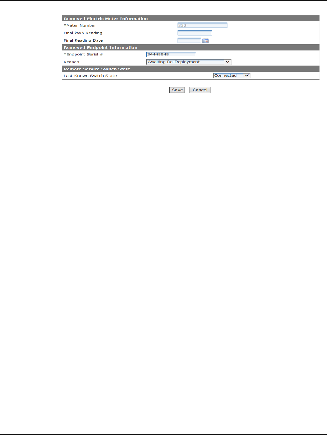
4. Select the Remove Enhanced Cellular Endpoint from Service link. The Remove Endpoint
From Service window will appear as shown below.
Draft
Chapter 4 - Deploying Endpoints Landis+Gyr
30 98-1723 Rev AB User Guide
Figure 4 - 9. Endpoint/Meter Selection
5. Fill in the Removed Meter Information data fields.
6. Enter the Final Reading (optional).
7. Enter the Final Reading Date (optional).
8. Enter the Removed Endpoint Information data. Select a reason for the removal from the drop-
down list box.
9. Awaiting Re-deployment status will appear. This option will transition the endpoint to
Inventory status.
10. Permanently Remove From Service. This option will archive the endpoint. An endpoint in
Archived status will not be included in any Command Center reports.
Click Save to activate the changes that were just made. A message indicating the success or failure
of the removal will be displayed.
Monitoring Deployment
Cellular Meter deployment may be monitored via the Deployment Status Report or the Installa-
tion Report.
Deployment Status Report
The Deployment Status Report can be used to track the progress of Cellular meter deployments for
a selected period of time. It provides a graphical overview of the deployment process for deploy-
ments not exceeding seven days, by default. The default number of deployment days aggregated can
be configured in Organization Information settings. Some of the data required for the Deployment
Status Report is provided via the Import Installation file.
Following is the procedure for generating the Deployment Status report:
1. Click Network > Deployment Status. The Deployment Status window will open.
2. Selection Criteria. Select the Collector radio button and select the desired collector from the
drop-down box to view statistics for a specific collector. Select All Collectors to see all
collectors/endpoint in the system.
3. Date Range. Enter a Start Date and End Date. Click the Calendar icon to view and use the
calendar for date selection.
4. Click OK. The Deployment Status Report will open, as shown in Figure 4 - 10.
Draft
Landis+Gyr Chapter 4 - Deploying Endpoints
User Guide 98-1723 Rev AB 31
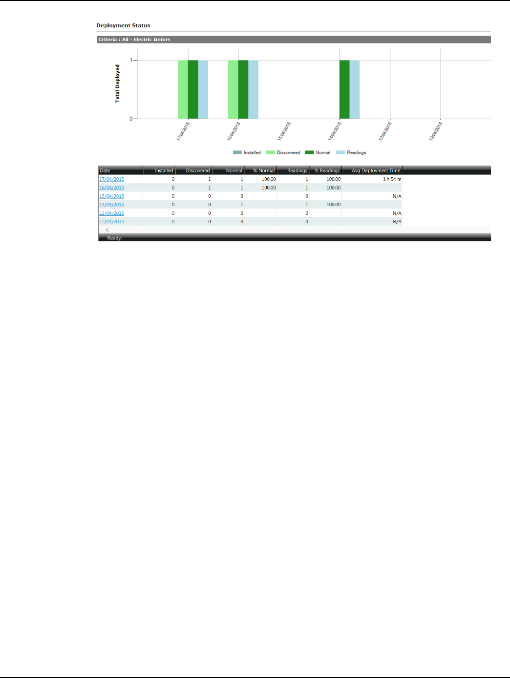
Figure 4 - 10. Deployment Status Report
The following information is displayed in the Deployment Status Report:
•Date. The Date column lists the dates used to generate the report.
•Installed. The Installed column indicates the number of meter modules installed on the
given date.
•Discovered. The Discovered column lists the total number of endpoints with
initialDiscovered status on the summary date.
•Normal. The Normal column lists the total number of endpoints with initial Normal status
on the summary date.
•%Normal. The %Normal column lists the percentage of Discovered endpoints which
transitioned to Normal status on the given day (Normal divided by Discovered).
•Readings. The Readings column lists the total number of readings received on the summary
date.
•%Readings. The %Readings column lists the percentage of Normal endpoints from which
readings were received on the summary date.
• Average Deployment Time. The Average Deployment Time column lists the average
amount of time taken for an endpoint to transition from initial Discovered state to Normal
state.
Click on a specific date to generate the Meters Deployed by Day Report, shown in the following
figure. This report provides a list of all meter modules included in the Deployment Status Report
with additional deployment details.

Draft
Chapter 4 - Deploying Endpoints Landis+Gyr
32 98-1723 Rev AB User Guide
Figure 4 - 11. Meters Deployed by Day
Installation Status
The Installation Status Report is intended to be used by utilities during mass deployment. It can be
used as an installation tool to determine how many meter modules have been installed over a speci-
fied time frame and, of those meter modules, how many:
•have been discovered.
•have moved to normal status.
•are sending readings.
•have sent readings in the past 24 hours.
Some of the data required for the Installation Status Report is provided via the Import Installation
file.
Following is the procedure for viewing the Installation Status report:
1. Click Network > Installation Status. The Installation Status window will open.
2. Selection Criteria. Select All to view results for all collectors in the system.
...or...
Select the desired collector from the drop down box to view results for only that collector or
select All to see all collectors/endpoints in the system.
3. Date Range. Enter a Start Date and End Date. Click the Calendar icon to view a calendar and
make date selections, if needed.
4. Click OK. The Installation Status Report will be displayed as shown in the next figure.
Draft
Landis+Gyr Chapter 4 - Deploying Endpoints
User Guide 98-1723 Rev AB 33
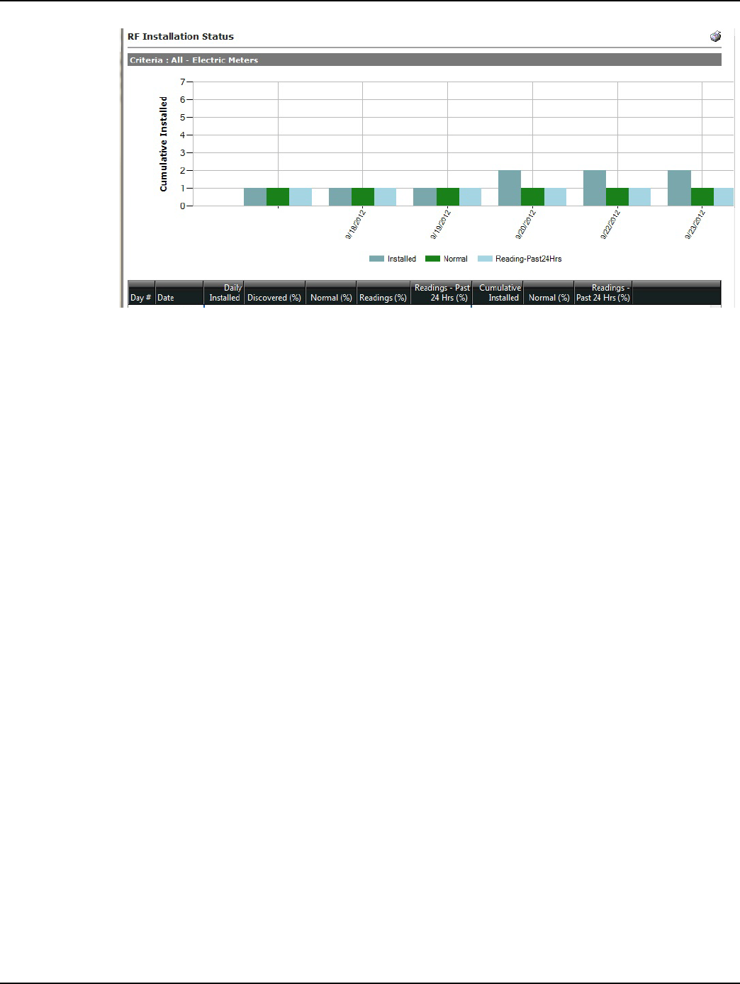
Figure 4 - 12. Installation Status
The following information is displayed in the report:
•Day. This number will increment for each day the user has selected to display.
•Date. This will display the dates selected in generation of the report. Click the date link to
view a list of all meter modules deployed on the selected date.
• Daily Installed. This will display the number of endpoints installed for that particular day.
The daily installed data is imported into Command Center via the Installation File.
•Discovered. Of the total number of meter modules installed on the summary date, the total
number of those that have transitioned into a Discovered state and the percentage
(Discovered meter modules/installed meter modules).
•Normal. Of the number of meter modules installed on the summary date, the total of those
meter modules that have transitioned to a normal state at that point in time and the
percentage (Normal meter modules/installed meter modules).
•Readings. Of the total number of meter modules installed on that day, the number of those
meter modules that have sent in a billable reading packet, and the percentage (meter
modules that have sent a billable reading packet/total meter modules installed on that day).
• Readings Past 24 Hours. Of the meter modules that were installed on that day, the total
number of meter modules that sent in a billable readings packet in the last 24 hours (from the
point the report was generated) and the percentage (meter modules that sent in a billable
readings packet in the last 24 hours/total meter modules installed on that day).
• Cumulative Installed. The total number of meter modules that have been installed up to
that date.
•Normal. The total cumulative number of meter modules that have transitioned to Normal
status up to that date.
The color-coded bar graph displays the following deployment information:
•Cumulative number of meter modules installed for each date (Grey).
•Current number of meter modules that have transitioned to Normal status (Green).
•Number of installed meter modules that have sent in a billable reading in the last 24 hours
(Blue).
Draft
Chapter 4 - Deploying Endpoints Landis+Gyr
34 98-1723 Rev AB User Guide
Module Alarms
In addition to displaying events associated with electric meter modules, the Meter Alarms section of
the AMI Dashboard, shown in the next figure, will display alarms reported by the modules.
Figure 4 - 13. Meter Alarms
Refer to “Module Events” later in this document for details of alarms reported to Command Center
by cellular modules.
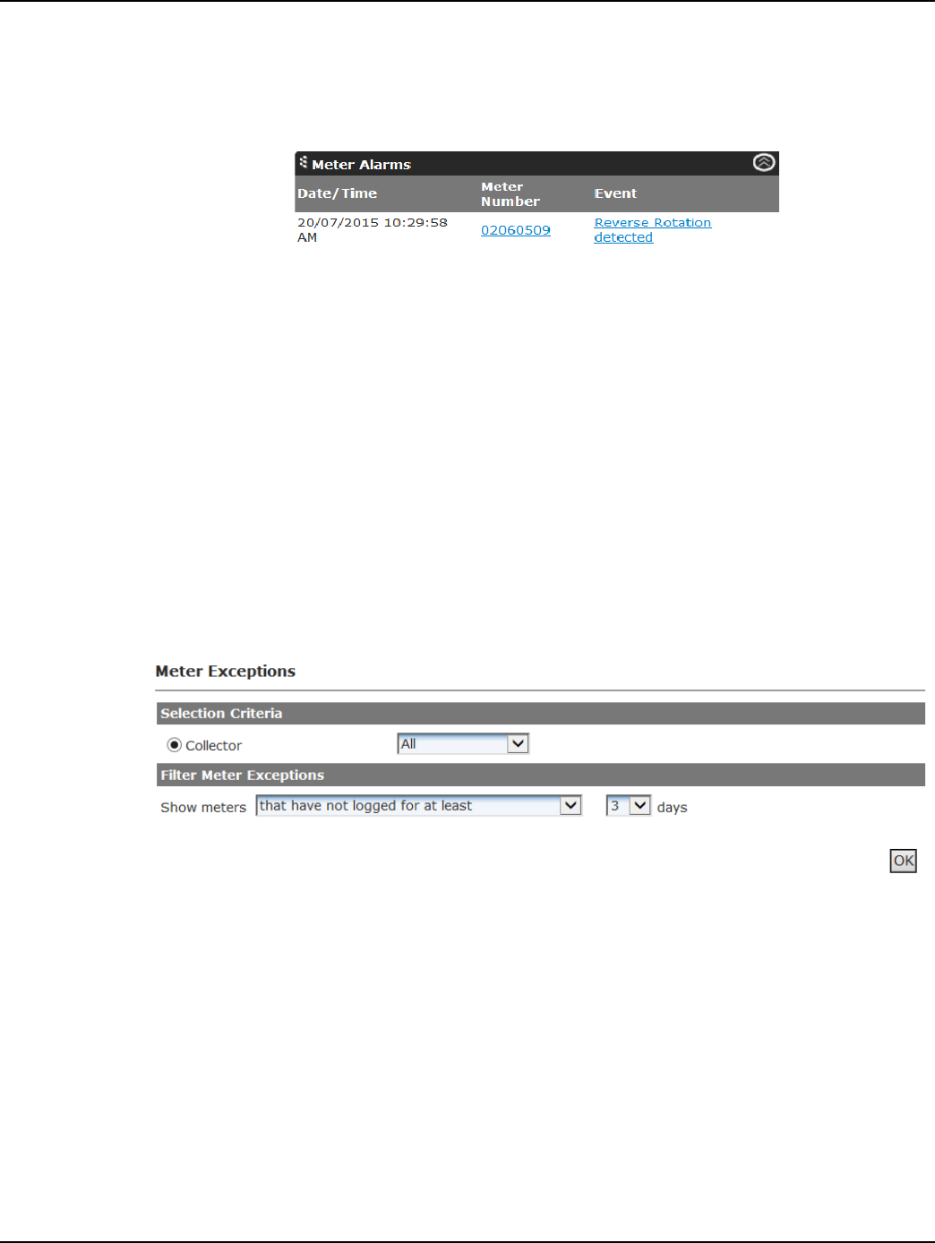
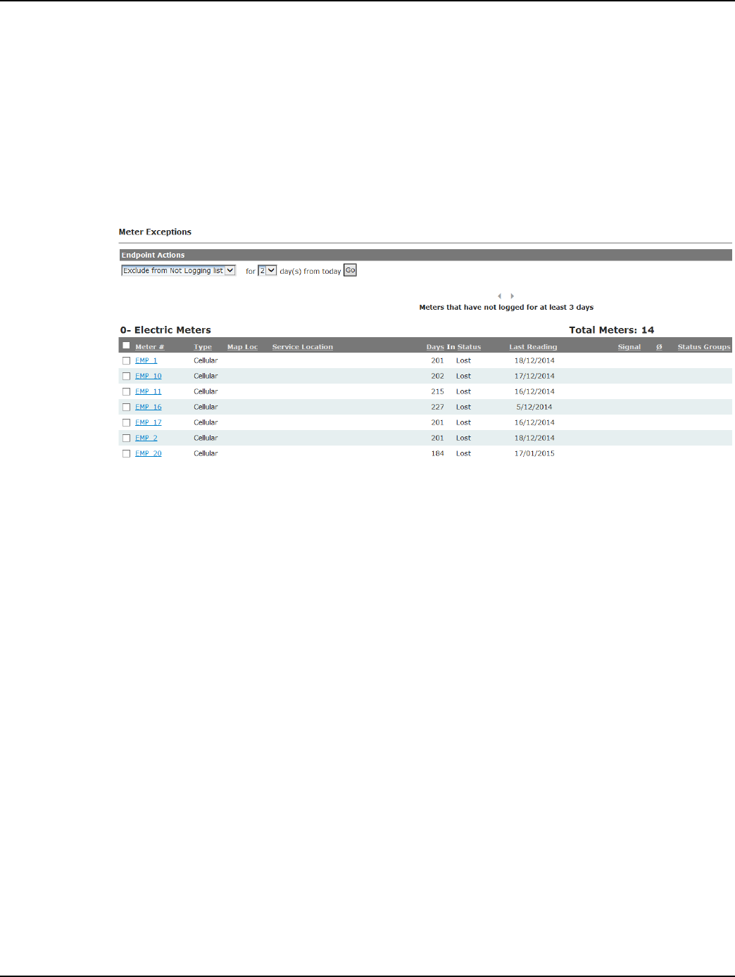
Meter Exceptions Report
The Meter Exceptions Report allows the user to view all endpoints that have not logged in a user-
defined number of days or endpoints that are logging, but are showing no usage. In addition, the
Meter Exceptions Report will provide a list of meter modules that have triggered the leak detection
event, in a user defined number of days.
Following is the procedure for generating the Meter Exceptions report:
1. Click Network > Meter Exceptions. The Meter Exceptions window will open, shown in the
next figure.
Figure 4 - 14. Meter Exceptions
2. Select from the following filtering options:
A. that have not logged for at least X days. This filter is useful in identifying the endpoints
that have stopped reporting potentially due to connectivity issues, faulty endpoint, etc.
B. that only had a billable packet X percent of the time during the past X days. This filter
is useful in identifying endpoints that are not consistently reporting valid readings,
indicating potential issue with either the module or the meter.
C. that have reported no usage for at least X days. This filter is useful in identifying
locations that have not shown consumption. If consumption is expected, troubleshooting
efforts should begin as this may indicate a faulty meter, module, or potential tampering.
D. that have never reported usage. This filter will identify meter modules that are in Normal
status but have not reported consumption since installation. If consumptions is expected,
Draft
Landis+Gyr Chapter 4 - Deploying Endpoints
User Guide 98-1723 Rev AB 35
troubleshooting efforts should begin as this may indicate an issue with the endpoint, a faulty
meter, or potential tampering.
E. that have not reported usage X % of the time in X days. This filter will identify meter
modules that are in Normal status but have been intermittently reporting consumption. If
consistent consumptions is expected, troubleshooting efforts should begin as this may
indicate an issue with the endpoint, a faulty meter, or potential tampering.
F. that are not communicating. This report is intended to identify devices that have not
reported daily reads or load profile data over the most recent 24 hours.
3. Click OK to generate the report. A sample report is shown in the following figure.
Figure 4 - 15. Meter Exceptions
Draft
Draft
User Guide 98-1723 Rev AB 37
5
Managing Endpoints
Cellular Endpoint Configuration
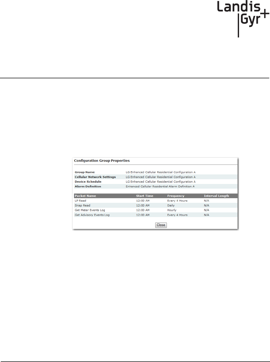
Configuration Groups
Cellular meters are automatically placed in the LG Enhanced Cellular Residential Configuration
Group A.
To view the configuration group, from Command Center home, select Setup > Groups > Cellular
Residential Meters.
Figure 5 - 1. Configuration Group Properties
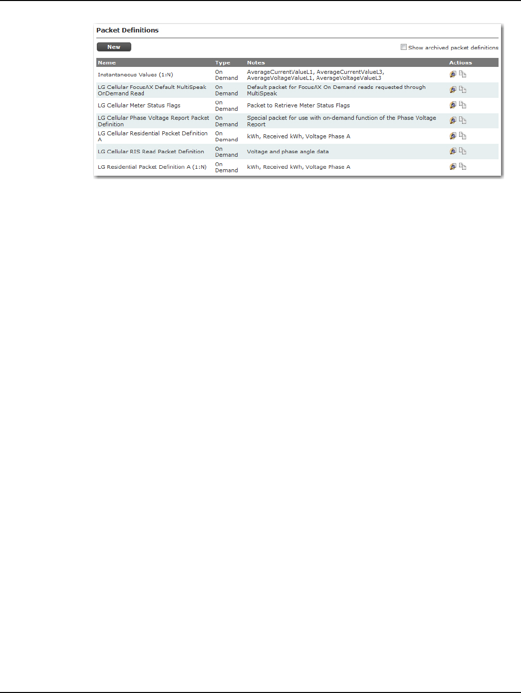
Packet Definitions
Packet Definitions are used to determine what data elements the endpoint will transmit. Endpoints
arrive from the factory in operational state with default packet definitions. There are multiple cellu-
lar packet definitions that are automatically seeded during the Command Center installation. These
packet definitions can be used for On Demand Read commands. New packet definitions can also be
created for On Demand Read commands.
To view the packet definition, from Command Center home, select Setup > Packet Definitions >
Cellular Residential.
Draft
Chapter 5 - Managing Endpoints Landis+Gyr
38 98-1723 Rev AB User Guide
Figure 5 - 2. Enhanced Cellular Residential Packet Definitions
The following actions may be performed:
•View. Select the View icon to open the selected Packet Definition and view its settings.
•Copy. Select the Copy icon to open a new Packet Definition window and duplicate the
settings from the selected packet definition.
•Edit. Select the Edit icon to open the Packet Definitions window and edit the description of
the selected packet definition.
•Delete. Select the Delete icon to delete the selected packet definition. This option will only
be available to user created Packet Definitions.
•Archive. Select the Archive icon to archive the selected packet definition. This will remove
the packet definition from all packet definition lists. This option is only available to user
created Packet Definitions.
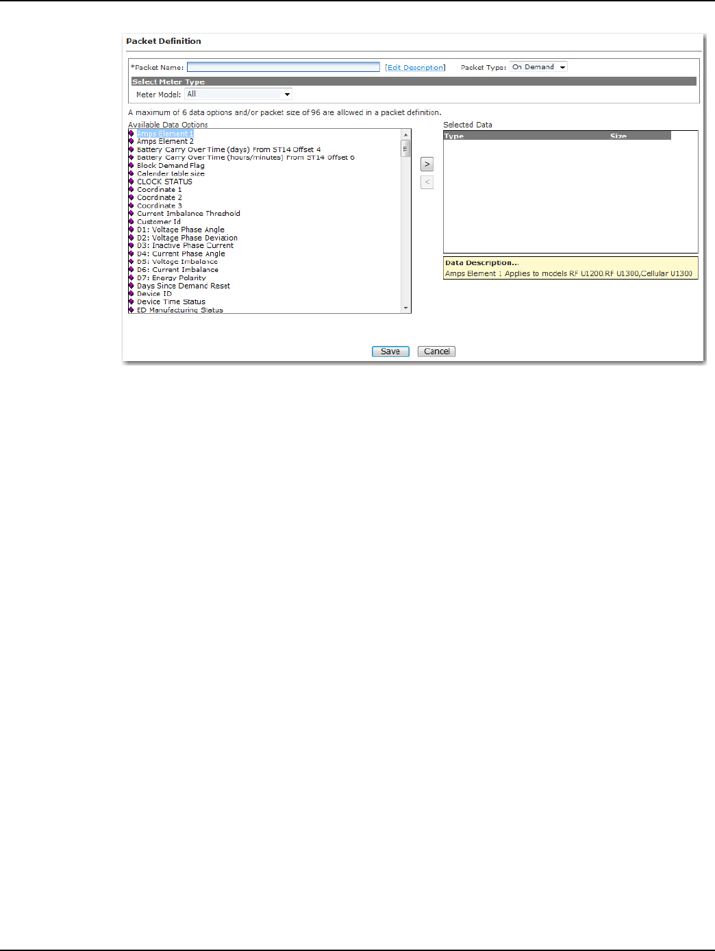
New packet definitions can be created for use with On Demand Read and/or Endpoint Configura-
tion. Following is the procedure for creating a custom packet definition:
1. From Command Center home, select Setup > Packet Definitions > Cellular Residential. The
cellular residential packet definition window will open.
2. Click the New button. The Packet Definitions screen will open.
Draft
Landis+Gyr Chapter 5 - Managing Endpoints
User Guide 98-1723 Rev AB 39
Figure 5 - 3. Packet Definition
3. Packet Name. Enter a name for the new packet definition that is unique to the organization.
4. Edit Description. Click the link (optional) to enter any desired notes for the packet definition. If
any notes were entered, click the OK button to save.
5. Packet Type. Select On-Demand.
6. Select Meter Type. Select the desired meter type from the drop down menu. Available data
options will vary based on the selected meter type.
7. Available Data Options. Double click the name of the items to be included in the packet. The
items will appear in the Selected Items data window. A packet may contain up to 6 data elements
and/or up to a packet size of 96.
8. Click Save to save the new packet definition. The Packet Definition window will open and the
newly created packet definition will appear in the list.
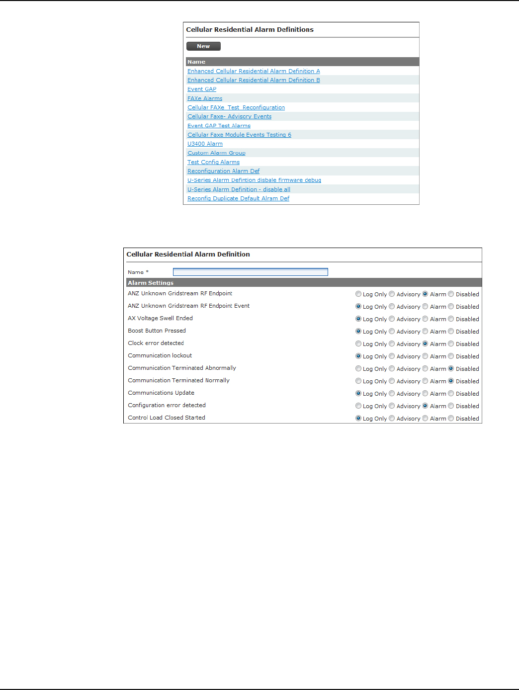
Alarm Definitions
Alarm Definitions determine what type of response the given Events will trigger, including Dash-
board Alerts and Email Alerts. Alarm Definitions must be created prior to Meter Configuration
Groups in order to be programmed to a module.
1. Click Setup > Alarm Definitions > Cellular Residential to display the Alarm Definitions
screen.
Draft
Chapter 5 - Managing Endpoints Landis+Gyr
40 98-1723 Rev AB User Guide
Figure 5 - 4. Cellular Residential Alarm Definitions
2. Click the New button to display the Cellular Alarm Definition screen.
Figure 5 - 5. Alarm Definition screen
3. Enter an Alarm Definition name in the Name field.
Draft
Landis+Gyr Chapter 5 - Managing Endpoints
User Guide 98-1723 Rev AB 41
4. Choose the desired setting for each event. See below for setting descriptions.
NOTE: NOTE: The default Alarm Definition settings represent the recommendation of Landis+Gyr.
5. Click the Save button.
An Alarm Definition can only be edited if it is not already part of an existing Configuration Group.
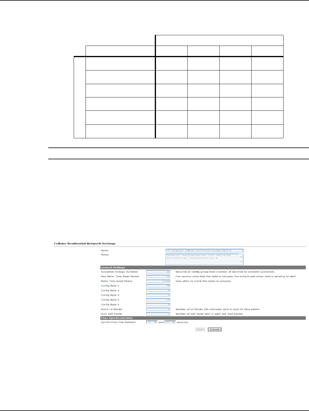
Cellular Residential Network Settings
The Cellular Residential Network Settings, shown in Figure 5 - 6, establish organization level set-
tings for outage wait values, time synchronization, etc. The Cellular Residential Network Settings
are a part of the endpoint configuration and may be modified.
Figure 5 - 6. Cellular Residential Network Settings
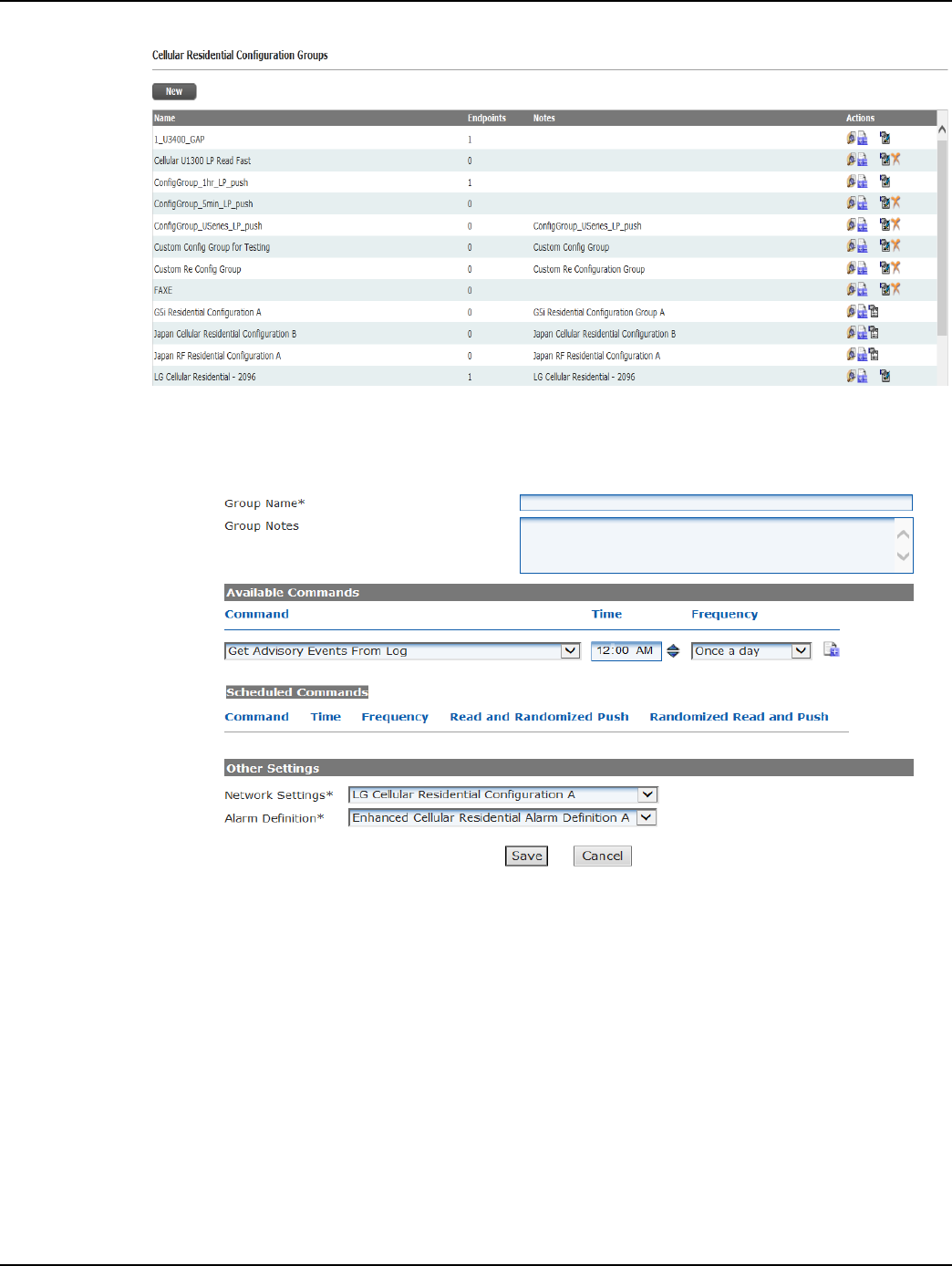
Customizing Cellular Configuration
Following is the procedure for creating a new Cellular Configuration Group
1. From Command Center home, select Setup > Groups > Configuration Groups > Cellular
Residential. The Cellular Residential Configuration Groups window will open, shown below
in Figure 5 - 7.
Table 5-1.
Available Settings
Result Disabled Log Only Advisory Alarm
Event is:
Logged in module
Available via request
Included in next scheduled
Transmitted immediately
Flagged on Dashboard
Included in E-mail Alerts
Draft
Chapter 5 - Managing Endpoints Landis+Gyr
42 98-1723 Rev AB User Guide
Figure 5 - 7. Cellular Residential Configuration Groups
2. Click New. The Cellular Residential Configuration Group Properties window will open, shown
in Figure 5 - 8.
Figure 5 - 8. Cellular Residential Configuration Group Properties
3. Group Name. Provide a name for the new cellular configuration group. This name must be
unique to the organization, and should indicate to the user how the group will be used.
4. Group Notes. (optional). Enter any relevant notes to describe this configuration group.
5. Available Commands:
•Command. Select the desired packet definition from the drop down list box.
•Time. Select the time that the command (reading) should occur.
• Frequency. Select how often the command should occur.
•N. If frequency “every n minutes” or “every n hours” was selected; enter the value of n.
•Select the + sign to schedule the RFS event. The event will appear under the Schedule
Commands.
Draft
Landis+Gyr Chapter 5 - Managing Endpoints
User Guide 98-1723 Rev AB 43
•Delay. Select the Delay check box to allow the endpoint to take a reading, but cache the
result for transmission at a different time.
Repeat step 5 for any additional commands. The endpoint has the ability to store twelve scheduled
commands.
6. Network Setting. Select the desired Network Settings group from the drop down box. Refer to
Network Settings for Network Settings configuration.
7. Alarm Definition. Select the desired alarm definition from the drop down list box. Refer to
Alarm Definitions for Alarm Definitions configuration.
8. Click Save to save the new configuration group.
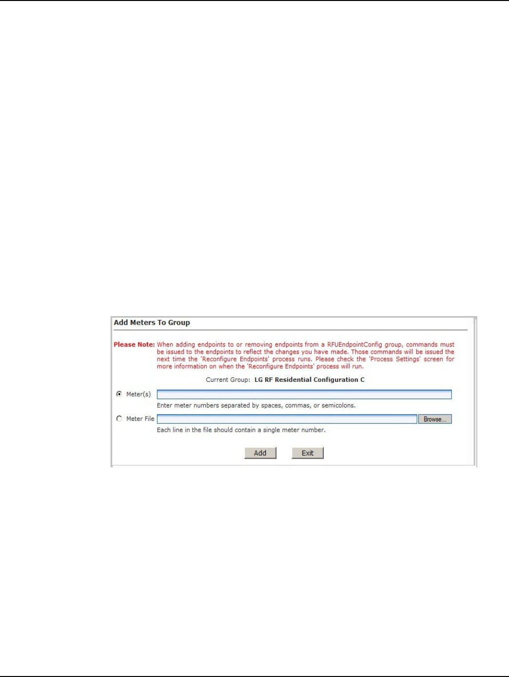
Add Meters to Configuration Group
The Add Meters to Group screen allows a user to add a meter, or group of meters, by entering the
meter number(s) or importing a formatted meter file.
Following is the procedure for adding meters to a configuration group:
1. From Command Center Home, select Setup > Groups > Endpoint Configuration Groups >
Cellular Residential. The Cellular Meter Configuration Groups window will open.
2. Select the Add Meters icon for the desired configuration group. The Add Meters to Group
window opens, shown in Figure 5 - 9.
Figure 5 - 9. Add Meters to Group window
3. Select the Meter Number radio button and enter the appropriate meter number(s). Meter
numbers should be separated by commas, spaces or semi-colons.
...or...
Select the Meter File radio button and enter the path to the meter file or select browse to
navigate to the file.
4. Select Add to save changes.
Cellular Reconfiguration Process
The Cellular Reconfiguration process is the process by which Command Center issues reconfigura-
tion commands to modules that have recently been added to a new Configuration Group or User
Draft
Chapter 5 - Managing Endpoints Landis+Gyr
44 98-1723 Rev AB User Guide
Defined Addressing Group. By default, this process runs once an hour. This schedule can be changed
in the Process Settings.
A cellular module will transition to Configure during reconfiguration. When the cellular module
responds to the configuration request, the module status will transition back to Normal.
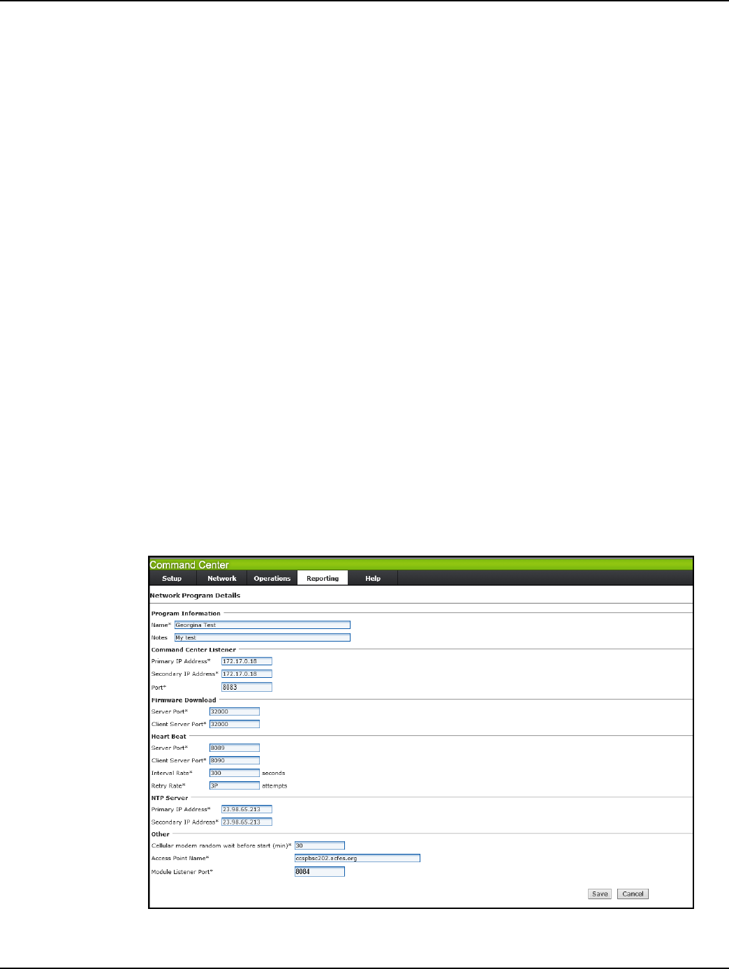
Enhanced Cellular Set Network Configuration Command
The Modify Network Program command allows the user to modify the cellular endpoint's communi-
cation parameters from Command Center. Changing any of these values to invalid values will break
the cellular endpoint's communication with the HES and there's currently no other way fix it over the
air. The meter will need to be configured in diag. mode.
As shown below, the same ports are used on both module and HES. Inbound for module will be out-
bound for HES and vice versa. So if the user changes the ports, the following M2M Adapter config
files will also need to be modified to use the new ports:
•..\Landis+Gyr\M2MAdapter\M2MListener\LandisGyr.CellularNMS.Listener.exe.config -
this config file has HES and firmware download ports.
•..\Landis+Gyr\M2MAdapter\HeartBeatListener\LandisGyr.CellularNMS.HeartbeatCommunic
ation.exe.config - this config file has the heart beat ports.
To use the command the user has to do the following:
1. Create a network program using the menu option Setup > Network Program.
2. Issue Set Network Configuration command from EIS screen > Manage tab or from the group
commands page.
The functionality listing/adding/editing/deleting a network program is similar to that of other config
pages like configuration groups.
Figure 5 - 10. Network Program Details Page

Draft
Landis+Gyr Chapter 5 - Managing Endpoints
User Guide 98-1723 Rev AB 45
UWARNING: Changing any of these values to invalid values will break the cellular endpoint's
communication with the HES and there's currently no other way fix it over the air. The meter
will need to be configured in diag. mode.
Values that will cause communication to break are designated in Bold Italic.
A network program allows the user to modify the following parameters:
Program Information
•Name. Name of the program.
•Notes. Any notes you would like to add.
Command Center Listener
•Primary IP Address. This is the Head End System's IP address. For Command Center, this
should be the M2M Adapter's IP address. Changing this IP address will cause the endpoints
to send all traffic to the new address. There's currently no way to fix the endpoints without
putting them in diag. mode.
• Secondary IP Address. This is a secondary HES IP address. This is currently not being
used by firmware.
•Port. This is the udp port used by the cellular endpoints to send outbound packets. The M2M
adapter listens on this port (default 8083).
Firmware Download
•Server Port. The udp port used by the cellular endpoints to send firmware download
packets. The M2M Adapter listens on this port.
•Client Server Port. The udp port the cellular endpoints use to receive firmware download
packets. The M2M Adapter sends on this port.
Heart Beat
•Server Port. The udp port used by the endpoints to send heart beat packets. The M2M
Adapter listens on this port.
•Client Server Port. The udp port used by the cellular endpoints to receive heart beat packets.
The M2M Adapter sends on this port.
• Interval Rate. The heart beat rate expressed in seconds (default is 300 seconds).
•Retry Rate. The heart beat failover threshold (default is 3 times).
NTP Server
•Primary IP Address. The IP address of the NTP server used by the cellular endpoints to get
time.
• Secondary IP Address. Secondary NTP server. This is currently not being used by the
firmware.
Other
• Cellular Modem random wait before start (min). Random wait in minutes before cell
modem is started up. This means the modem will wait a random number of minutes between
0 and this number (default 30 minutes).
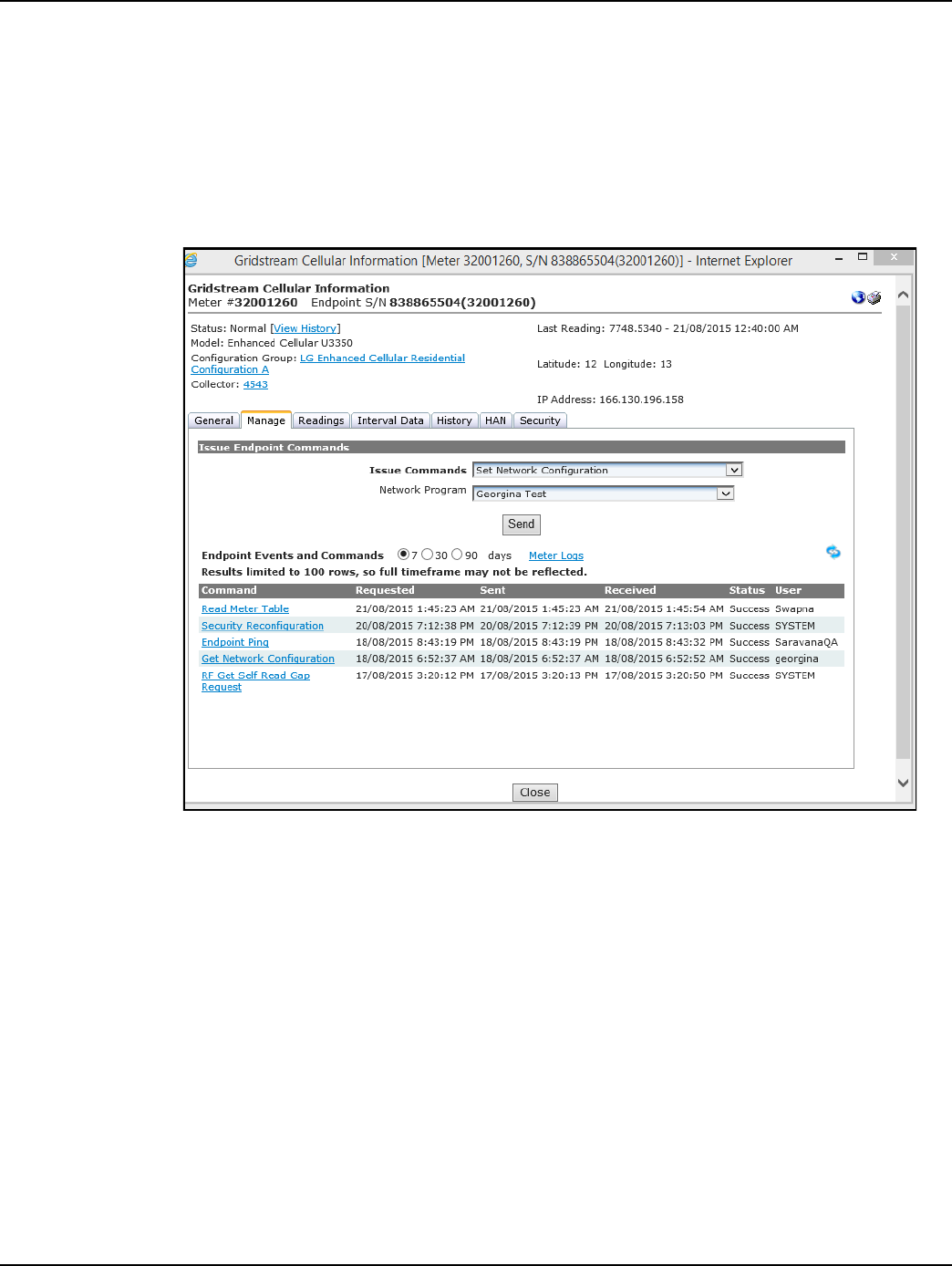
Draft
Chapter 5 - Managing Endpoints Landis+Gyr
46 98-1723 Rev AB User Guide
•Access Point Name. Name of the APN server used for communication between mobile
network carrier and M2M Adapter.
•Module Listener Port. The udp port used by the endpoint to receive packets. The M2M
Adapter sends on this port (default 8084).
To send command from EIS Manage tab or Group command page:
1. Select Set Network Configuration, and select a network program from the drop down as shown
in Figure 5 - 11.
Figure 5 - 11. Manage Tab
2. To read current configuration on the meter, issue the Get Network Configuration command as
shown in Figure 5 - 12.
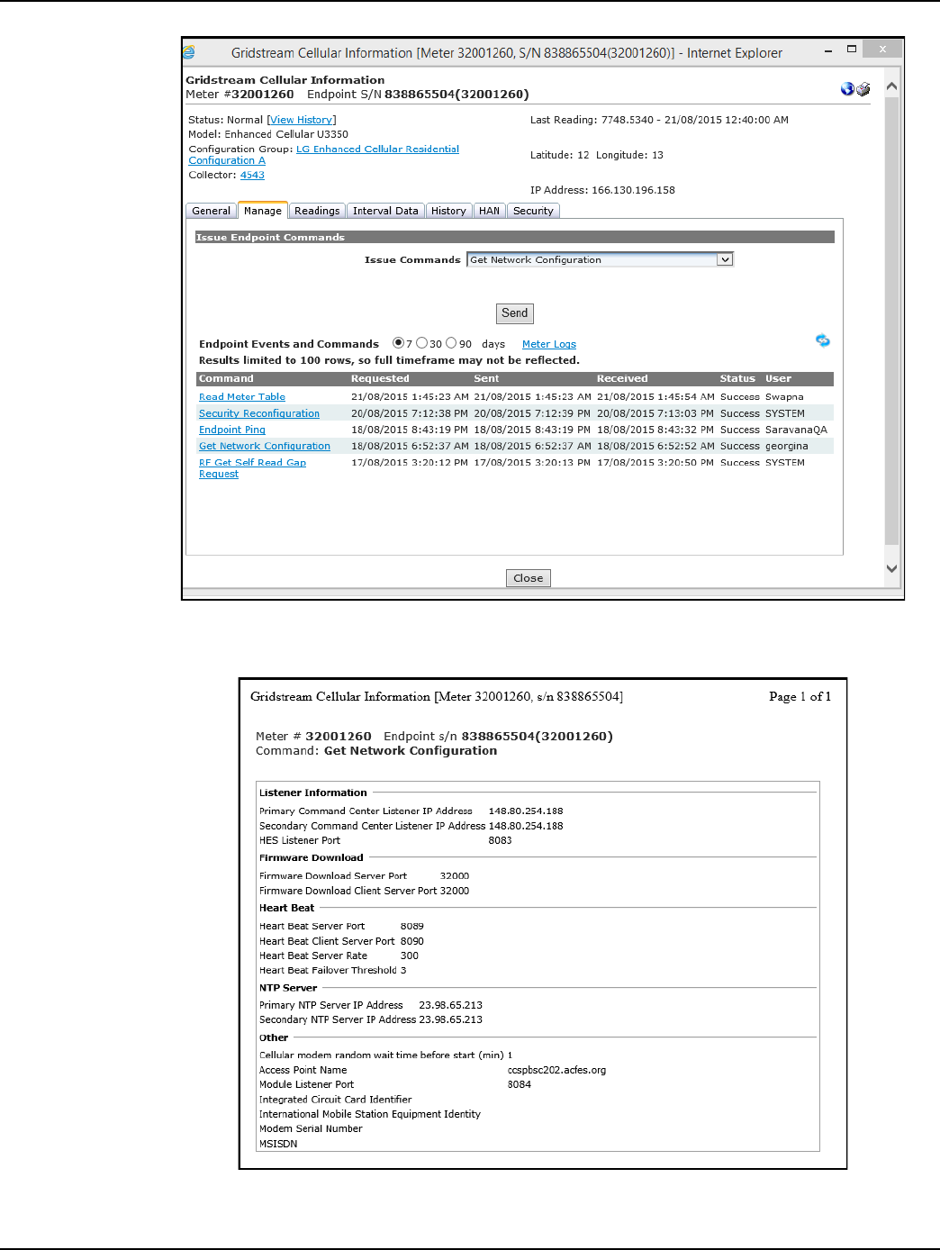
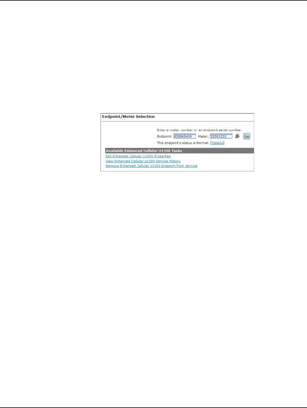
Draft
Chapter 5 - Managing Endpoints Landis+Gyr
48 98-1723 Rev AB User Guide
Managing Cellular Endpoints
Gridstream Cellular Information Window
1. Click Operations > Endpoints.
The Endpoint/Meter Selection window will open.
2. To edit existing meter or endpoint information, enter the desired endpoint or meter number in the
corresponding field or click the Find a Meter icon to search for a meter and click the Go button.
The current status of the endpoint and the list of Available Tasks for the selected Endpoint/Meter
Selection are displayed.
Figure 5 - 14. Available Tasks
3. Click the Details link to display the Gridstream Cellular Information window.
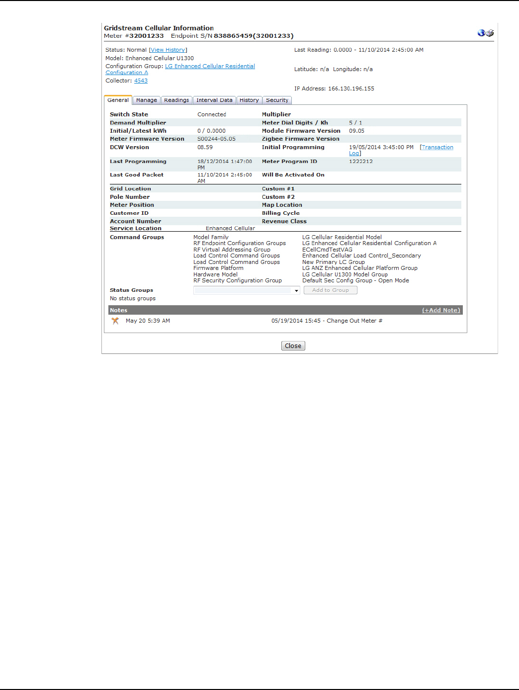
Draft
Landis+Gyr Chapter 5 - Managing Endpoints
User Guide 98-1723 Rev AB 49
Figure 5 - 15. Endpoint Information Window
In the top section of the Endpoint Information window the following information will be displayed:
• Meter #. Displays the number associated with the selected endpoint.
• Endpoint S/N. Displays the Landis+Gyr - assigned serial number of the endpoint in the
selected meter.
• Status. Displays the current system status of the endpoint. Click the View History link to
view the status changes for the selected meter.
• Last Reading. Displays the last kWh reading and the date and time it was received.
•Model. Displays the meter model.
• Configuration Group. Click the Configuration Group link to view the Configuration Group
Properties menu.
• Collector. Displays the name of the virtual collector identifier.
• Latitude/Longitude. Displays the latitude and longitude of the endpoint.
• IP Address. Shows the selected endpoint’s Wide Area Network address.
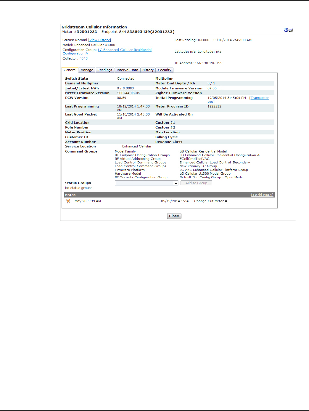
Draft
Chapter 5 - Managing Endpoints Landis+Gyr
50 98-1723 Rev AB User Guide
General Tab
Figure 5 - 16. General Tab
The General Tab displays the following information:
•Switch State. The switch state indicates whether the meter is connected or disconnected.
• Multiplier. N/A
• Demand Multiplier. N/A
• Meter Dial Digits/Kh. Displays the number of dials in the meter and the meter’s Kh.
• Initial/Latest kWh. Displays the original kWh of the endpoint and the latest reported kWh.
• Module Firmware Version. Displays the current firmware version of the endpoint/module.
• Meter Firmware Version. Displays the current firmware version of the meter.
• ZigBee Firmware Version. Displays the current Zigbee firmware version.
• DCW Version. Displays the current DCW version.
• Initial Programming. Displays the original endpoint programming date.
• Last Programming. Displays the most recent programming date.
• Meter Program ID. Displays the Meter Program ID for all electric meters.
•Last Good Packet. Displays the date and time the last good packet was received.
•Pending Firmware Version. Shows the pending firmware version when a firmware
download is in progress.

Draft
Landis+Gyr Chapter 5 - Managing Endpoints
User Guide 98-1723 Rev AB 51
• Firmware Download Status. Displays the status of the current Endpoint Firmware
Download command.
• Will Be Activated On. Displays the date that a scheduled firmware will be activated.
•Grid Location. Displays the meter’s grid location (if applicable).
•Custom #1. Displays the ICCID associated with this meter.
•Pole Number. Displays the meter’s pole number.
•Custom #2. User defined data field.
• Meter Position. Displays the endpoint’s meter position (if applicable).
•Map Location. Displays the endpoint’s map location (if applicable).
•Customer ID. Displays the customer’s identification number (if applicable).
• Billing Cycle. Displays the current billing cycle.
• Account Number. Displays the customer’s account number (if applicable).
• Revenue Class. Displays the revenue class. (if applicable).
• Service Location. Displays the customer’s service location (if applicable).
• Command Groups. Displays any Command Addressing Groups to which the module
belongs.
• Status groups. Allows the user to add endpoints to a available status groups
To add the endpoint to a status group:
•Select a status group from the drop-down list box.
•Click the Add Group icon.
•Notes. Displays any notes entered into the system previously. Select the Add Note plus (+)
sign to add a new note.
Manage Tab
The Gridstream Cellular Information – Manage tab allows the user to issue commands to the current
endpoint and view commands previously sent to the endpoint.
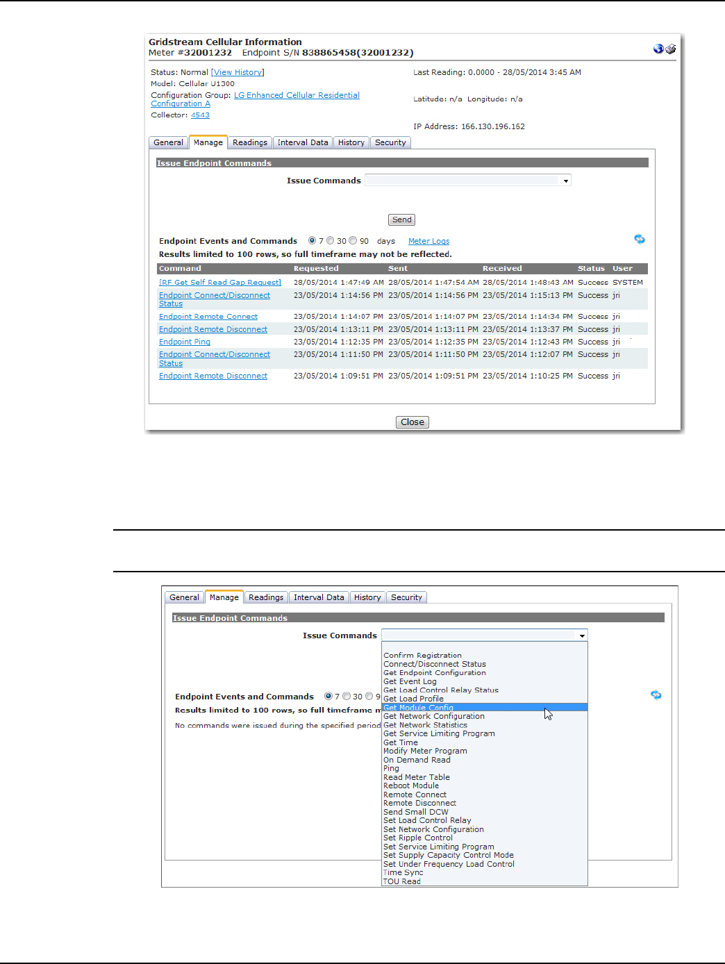
Draft
Chapter 5 - Managing Endpoints Landis+Gyr
52 98-1723 Rev AB User Guide
Figure 5 - 17. Gridstream Cellular Information Window
For group commands, cellular meters can be added to Virtual Addressing Groups.
Issue Endpoint Commands
NOTE: NOTE: The commands displayed will be dependent upon the permissions granted to the
user, the selected endpoint and the activated Command Center license(s).
Figure 5 - 18. Issue Commands Selections Vary for Different Endpoint Types

Draft
Landis+Gyr Chapter 5 - Managing Endpoints
User Guide 98-1723 Rev AB 53
The following commands are supported in Command Center 6.3 MR1 for the Gridstream Enhanced
Cellular
Table 5-2. Supported Commands
Name Description
Confirm Registration This command will manually send a confirm registration request to the
endpoint
Connect/Disconnect Status This command returns the current connection status of the FOCUS AX/SD
meter, as well as load side and line side voltage data
Demand Reset This command resets the peak registers in the meter and will return the
Demand Reset Data.
Demand Reset/Cancel
Scheduled Demand Reset
This command allows the user to reset demand and cancel any future
scheduled demand resets already sent to the meters. When selected, the
user will be able to choose whether to cancel demand reset and reset the
demand, or simply cancel demand reset.
Endpoint Firmware
Download
This command allows the user to select from a drop down box the desired
module firmware. The user may choose to download the firmware
immediately, or select a firmware activation date/time. Downloads both the
module firmware and the DCW.
Get Endpoint Configuration This command returns Init push information for electric meters/routers and
mesh extenders.
Get Event Log
This command allows the user to select from a drop down list of event logs
(HAN Events, Standard Meter Events, Manufacturer Meter Events, All
Events) logged over a selected number of days.
Get Load Profile This command retrieves and displays an on request read of load profile date.
The user is able to enter the desired date/time range.
Get Module Config
This command returns information that is not related to the meter, but key
configuration of the module associated with the meter. It will return the
confirmation that the AMR password is valid, the endpoint’s CRC, and time
validation information.
Get Network Configuration Allows the user to view the Command Center Listener address list
associated with the endpoint and other modem settings.
Get Network Statistics Allows the user to view IP and UDP statistics for the cellular radio.
Get Service Limiting
Program
This command will display any service limiting program currently loaded in
the meter.
Get Time The Get Time command response returns the meter date and time and the
endpoint date and time.
HAN: Clear Devices This command clears all of the HAN devices associated with meter.
HAN: Commission Network This command will create the HAN network for the meter.
HAN: Decommission
Network
This command may be issued to disable a HAN network in the case of a
customer move out.
HAN: Delete Device This command removes a HAN device from an endpoint.
HAN: Firmware Download This command downloads the HAN firmware to the meter.
HAN: Get All Devices Info This command will return information about all of the HAN devices

Draft
Chapter 5 - Managing Endpoints Landis+Gyr
54 98-1723 Rev AB User Guide
HAN: Get Device Info This command returns device information for a single device by MAC
address and Short ID.
HAN: Get Firmware This command will return the firmware version of the HAN device associated
with this endpoint.
HAN: Get Network Info
Returns HAN Channel ID and HAN Personal Area Network ID. This
information is useful in determining whether a HAN network has been
commissioned.
HAN: Initialization This command initializes of the HAN device registers to properly display the
TOU registers on the HAN device.
HAN: Ping Device This command will issue a ping to the HAN device.
HAN: Register Device This command will join a HAN device to the meter.
HAN: Send Message Allows the user to transmit a message to be displayed on the consumers
HAN device.
Meter Firmware Download Allows the user to push out new meter firmware over the air.
Modify Meter Program Allow for selecting from a predefined list of meter programs for transmission
to the meter.
On Demand Read This command will return the specified packet working in conjunction with a
pre-defined packet definition.
Optic Lockout This command allows the user to enable/disable/view status of optical probe
access.
Ping
This command returns a basic response from the endpoint. This command
is useful in determining if communication is available to the endpoint via the
mesh network.
Read Demand Reset Data This command will return from the meter the data captured upon the last
demand reset.
Read Meter Table
This command provides the ability to read ANSI C12.19 table from meter.
The response is a list of table, offset, length, and data. When the data is
returned from the meter it can be displayed in two formats, one is the RAW
format as returned by the meter and the other is the interpreted format. A
simple check box allows the user to choose which format is displayed.
Reboot Module Requests the module to perform a reboot.
Remote Connect
This command instructs the meter to connect power at the consumer
location. This process automates the connect process, the consumer does
not have to activate the service.
Remote Disconnect This command instructs the meter to disconnect power at the consumer
location.
Send Small DCW Command allows user to send a small DCW to an endpoint.
Reset Meter Data Allows the user to zero out the meter readings.
Set Network Configuration Allows the user to change the Command Center Listener address list
associated with the endpoint among other modem settings.
Set Service Limiting Allows the user to set a service limiting program to the meter.
Table 5-2. Supported Commands (Continued)
Name Description
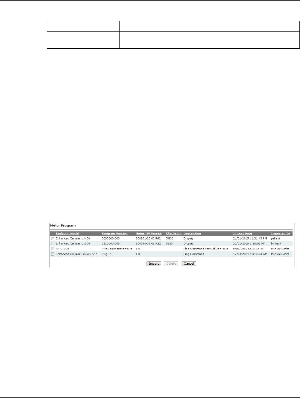
Draft
Landis+Gyr Chapter 5 - Managing Endpoints
User Guide 98-1723 Rev AB 55
Endpoint Events and Commands
•Select the 7, 30, or 90 days radio buttons for expanded data.
•Select the Meter Logs link to open the Log Viewer for the meter.
...or...
•View the events and commands in the manage window.
The Commands section displays the following information:
•Command. Displays the command that was issued.
• Requested. Displays the date requested.
•Sent. Displays the date sent.
• Received. Displays the date received.
• Status. Displays the status of the command.
•User. Displays the user that sent the command.
Import Meter Program
The Import functionality, Setup > Firmware > Meter Program is used to import Cellular endpoint
models when a meter program file has been imported.
Figure 5 - 19. Import Meter Program
Interval Data Tab
The Interval Data tab displays a graph and chart of interval data received from the endpoints for the
last day by default.
Time Sync This command request the endpoint synchronize its time within established
boundaries.
Table 5-2. Supported Commands (Continued)
Name Description
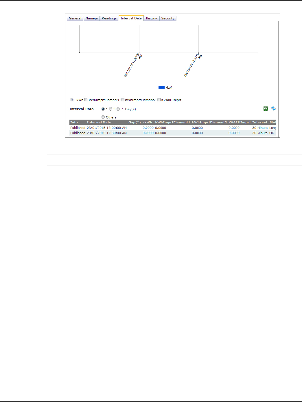
Draft
Chapter 5 - Managing Endpoints Landis+Gyr
56 98-1723 Rev AB User Guide
Figure 5 - 20. Interval Data Tab
NOTE: NOTE: Filter graph view by selecting any available filer or all.
The Interval Data screen provides the following information, columns displayed will vary by meter
program:
•Info. The Info column lists the method in which the data was provided. A Published Packet
refers to a packet that was transmitted by the endpoint.
• Interval date. The Interval date column lists the time and date the interval data was
measured.
•Gap (*). An asterisk in this column indicates that there are gaps between readings. The
missing intervals will be listed in the Interval Data Gaps section of the Interval tab.
• Interval. The Interval column lists the interval over which usage was measured.
• Status. Indicates the quality of the interval data (OK, short, etc.)
The data can be filtered to display the last 1, 3, or 7 days or by a specific date by selecting the Others
option and choosing the date.
History Tab
The History tab provides a list of the events and errors associated with the endpoint.
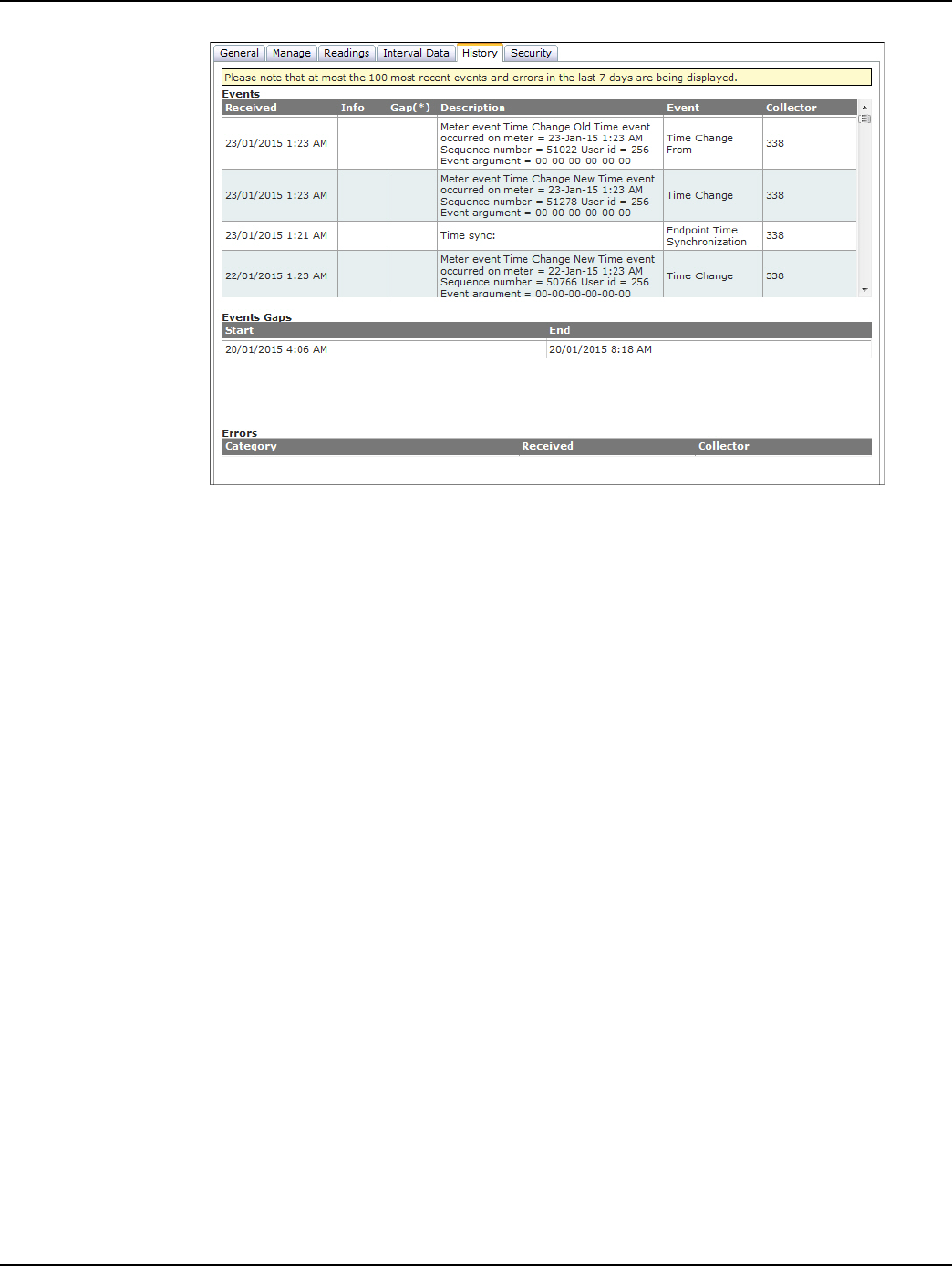
Draft
Landis+Gyr Chapter 5 - Managing Endpoints
User Guide 98-1723 Rev AB 57
Figure 5 - 21. History Tab
The following data is provided in the History screen:
•Events. Provides description of the event generated.
• Received. The received column lists the date and time the event occurred.
• Description. The description column describes the event.
•Event. The event column provides the name of the event.
• Collector. The collector column lists the virtual collector identifier the endpoint is
associated with.
•Errors.
• Category. The category column lists the type of event, command or error that has
occurred.
• Received. The received column lists the date and time the event, command or error
occurred.
• Collector. The collector column lists the virtual collector identifier the endpoint is
associated with.
Security Tab
The Security tab provides a place for the security administrator to send endpoint commands related
to security settings.
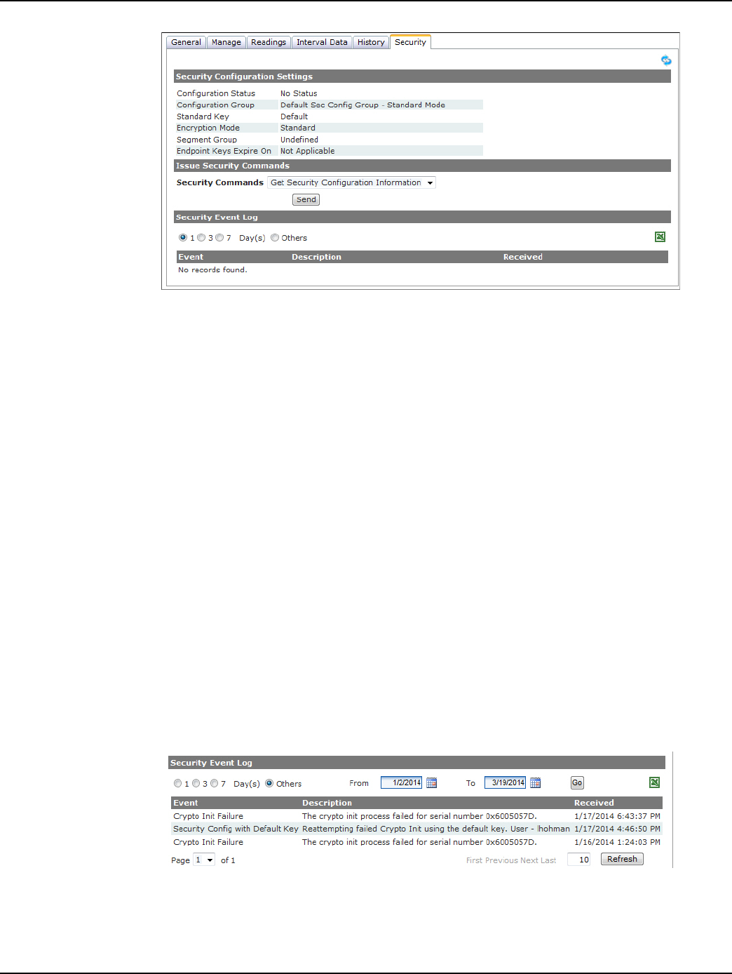
Draft
Chapter 5 - Managing Endpoints Landis+Gyr
58 98-1723 Rev AB User Guide
Figure 5 - 22. Security Tab
Security Configuration Settings
The Security Configuration settings are displayed:
• Configuration Status. The endpoint's security configuration status.
Valid values are Normal, Processing Keys, Distributing Keys, Failed and No Status. See
Endpoint Security Status section for further information.
• Configuration Group. The endpoint's current Security Configuration Group.
• Standard Key. The endpoint's standard security key.
Valid values are: Default, Endpoint, Current System Key, and No Standard Key.
• Encryption Mode. Valid values are: Open, Standard, Advanced.
•Segment Group. N/A
• Endpoint Key Expires On. N/A
Security Event Log
To view the Security Event Log.
1. Select either the 1, 3 or 7 Day(s) radio button or select Others and select from a date range.
2. Click the Go button to view the events. Events may be also be viewed by selecting the Excel
icon.
Figure 5 - 23. Security Event Log
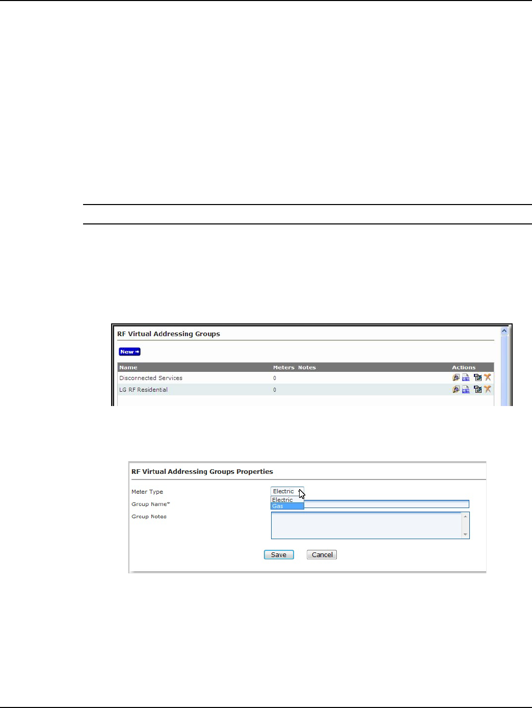
Draft
Landis+Gyr Chapter 5 - Managing Endpoints
User Guide 98-1723 Rev AB 59
Group Addressing
Commands may be issued to endpoints point to point, as described previously, or by group. Group
addressing may be use to efficiently communicate with endpoints in the field.
Virtual Addressing Groups
Virtual Addressing Groups may be created for efficiently transmitting commands to specific end-
points. Commands issued to members of virtual addressing groups are not broadcast, each command
is sent individually to the endpoint.
Virtual addressing group membership is NOT part of the endpoint configuration, and will not require
a reconfiguration.
NOTE: Broadcast commands are not supported with Cellular Meters.
Create Virtual Addressing Group
Following is the procedure for creating Virtual Addressing Groups:
1. Select Setup > Groups > Virtual Addressing Groups. The RF Virtual Addressing Groups
window will open, shown in Figure 5 - 24.
Figure 5 - 24. RF Virtual Addressing Groups
2. Select New. The RF Virtual Addressing Groups Properties window will open, shown in
Figure 5 - 25.
Figure 5 - 25. RF Virtual Addressing Groups Properties
3. Meter Type. Select Electric or Gas from the drop down list.
4. Group Name. Enter a name for the new addressing group. The name must be unique to the
organization.
5. Group Notes (Optional). Entered any desired notes.
6. Click Save. The newly created group is now displayed in the User Defined Addressing Group
window.
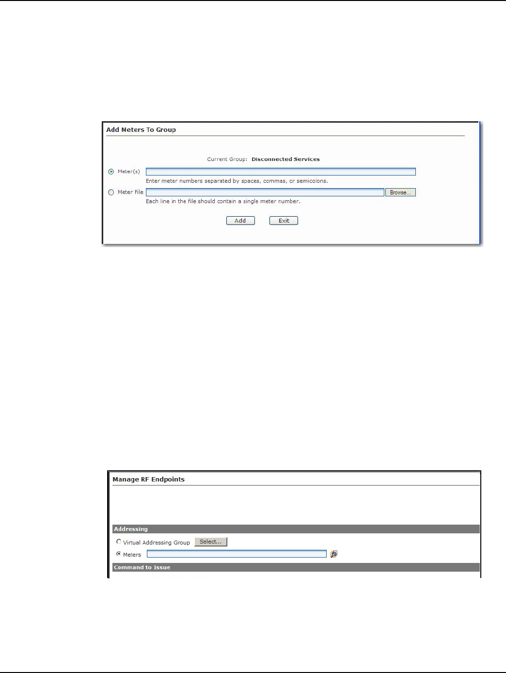
Draft
Chapter 5 - Managing Endpoints Landis+Gyr
60 98-1723 Rev AB User Guide
Add Meters to Virtual Addressing Group
Following is the procedure for adding meters to a Virtual Addressing Group:
1. From Command Center home, select Setup > Groups > Virtual Addressing Groups. The
Virtual Addressing Groups window will open, as shown previously in Figure 5 - 25.
2. Select the Add/Remove Meters icon for the desired group. The Add Meters to Group window
will open, as shown in Figure 5 - 26.
Figure 5 - 26. Add Meters to Group
3. Enter the desired meter numbers separated by colons, semi-colons, or spaces in the Meter
Number text box.
...or...
Select Meter File and enter the path to a file that contains the meters to be added to the group.
Click the Browse button to navigate to the appropriate file is necessary.
4. Click Add to add meters to the group.
Issuing Virtually Addressed Commands
Following is the procedure to issue a command to a Virtual Addressing Group:
1. Select Network > Endpoints > Cellular Residential. The Manage RF Electric Endpoints
window will open, shown in Figure 5 - 27.
Figure 5 - 27. Manage RF Endpoints
2. Addressing. Select Virtual Addressing Group, then click the Select button to view a list of
addressing groups.
...or...
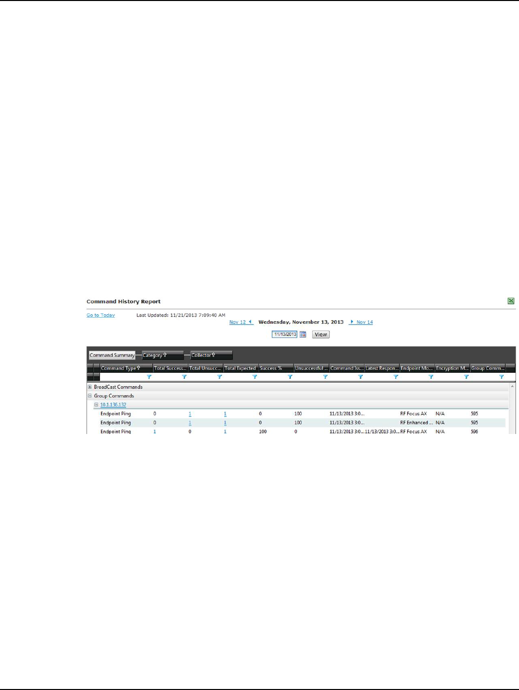
Draft
Landis+Gyr Chapter 5 - Managing Endpoints
User Guide 98-1723 Rev AB 61
Select Meters, then enter desired meters separated by space, commas or semi-colons.
3. Command to Issue. Select the desired command from the drop down list box.
4. Click Send. The Manage endpoints screen will display a message confirming the success or
failure of the command issued.
The results of virtually addressed commands can be viewed on the Endpoint Information screen
Manage tab, in the Log Viewer Commands.
Command History Report
When a command request is initiated, Command Center will retrieve all of the endpoints that match
the selection criteria (based on data stored in Command Center). The count will be stored in the
Expected total on the Command History Report.
Following is the procedure for generating the Command History Report:
1. Select Reports > Command History Report. The Command Summary window will open
displaying all group commands on the current date, shown in Figure 5 - 28.
The Command Summary features the Webgrid interface which allows for many sorting and
export options.
Figure 5 - 28. Command Summary
2. Click the plus (+) sign adjacent to any collector to expand and view commands issued to
endpoints on the selected collector.
3. Click the plus (+) sign adjacent to Group Commands.
The following information is displayed:
• Command Type. Name of the command.
• Total Successful. Indicates endpoints that successfully responded to the command.
• Total Unsuccessful. Indicated endpoints that were expected to respond successfully but
did not.
•Total Expected. Indicates the total number of endpoints that are expected to respond to
the command.
• Success %. The percentage of successful responses, when compared to the total
expected.
• Unsuccessful %. The percentage of unsuccessful responses, when compared to the total
expected.
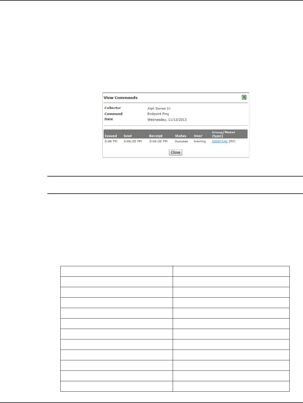
Draft
Chapter 5 - Managing Endpoints Landis+Gyr
62 98-1723 Rev AB User Guide
• Command Issued. Indicated the time and date the command was issued.
• Latest Response. Indicates the time the last response was received to the command
from an endpoint.
• Endpoint Model. Indicates the type of endpoint the command was issued for.
• Encryption Mode. Indicates the encryption mode that was used to send out the
command.
Select the numbered link of Total or Expected to view a list of meters. The results to a Ping are
shown in Figure 5 - 29.
Figure 5 - 29. View Commands
NOTE: Process Setting: The Command History Report Batch Process must be enabled in the
Process Settings for the report to work. The process is defaulted to enabled and to run every 4 hours.
Reports
Command Center 6.3 MR1 and later supports the following reports for the Gridstream Enhanced
Cellular. For more information on these reports, please refer to the Command Center Users guide.
publication 98-9108.
Table 5-3. Supported Command Center Reports
Report Name Path in Command Center
Assign Meters to Billing Cycles Reporting > Billing
Billing Cycles Reporting > Billing
Billing Progress Report Reporting > Billing
Data Extract -> Conventional Reporting > Billing
Data Extract -> Interval Reporting > Billing
Interval Data Extract Reporting > Billing
Incremental Daily Reads Extract Reporting > Billing
Endpoint Data Extract Reporting > Endpoint Data Extract
Scheduled Endpoint Data Extract Reporting > Endpoint Data Extract
Meter Change Out Reporting > Meter Change Out
Meter Program Status Report Reporting > Meter Program Status Report

Draft
Landis+Gyr Chapter 5 - Managing Endpoints
User Guide 98-1723 Rev AB 63
Endpoint Information Reporting > Endpoint Information
Service History Reporting > Service History
Usage Report > Electric Reporting > Usage Report
Usage Report > Electric Overall Reporting > Usage Report
Usage Report > High Usage/High Demand Reporting > Usage Report
Log Viewer > Commands Reporting > LogViewer Commands
Log Viewer > Errors Reporting > LogViewer Errors
Log Viewer > Events Reporting > Events
Log Viewer > Security Events Reporting > Security Events
Log Viewer > Meter Logs Reporting > Meter Logs
Log Viewer > Security Events Reporting > Security Events
Service History Reporting > Service History
Log Viewer > Meter Logs Reporting > Meter Logs
Command History Report Reporting > Command History Report
Virtual Disconnect Report Reporting > Virtual Disconnect Report
Momentary Interruptions Alert Reporting > Validation Group Report
Monthly Usage Threshold Alert Reporting > Validation Group Report
Sustained Interruptions Alert Reporting > Validation Group Report
Total Usage Threshold Alert Reporting > Validation Group Report
Unexpected Demand Alert Reporting > Validation Group Report
Voltage Threshold Alert Reporting > Validation Group Report
Daily Usage Alert Reporting > Validation Group Report
Full Register Reads Alert Reporting > Validation Group Report
Residential Interval Threshold Alert Reporting > Validation Group Report
Unexpected Load Side Voltage Alert Reporting > Validation Group Report
Daily Reads Status Report Reporting > Daily Reads Status Report
Table 5-3. Supported Command Center Reports (Continued)
Report Name Path in Command Center
Draft

Draft
User Guide 98-1723 Rev AB 65
6
Scheduled Demand Reset
Scheduled Demand Resets
The purpose of the demand reset is to capture peak demand values and the times at which those val-
ues were recorded since the last time the reset procedure was executed. Scheduled Demand Resets
may be performed based on Billing Cycle membership, or based on Virtual Addressing Group
membership. Only endpoints in Normal status will be sent the scheduled Demand Reset command.
Demand Reset Process
A Demand Reset can be set up as a Scheduled Read in Command Center. Once the demand reset
date is scheduled, X days prior to the demand reset date Command Center will send 2 scheduled
tasks to the endpoints included in the demand reset. The value X is a configurable System Setting in
Command Center called the Scheduled Demand Reset Window to send Commands and must be
between 2-21 days. The two scheduled tasks sent to the endpoints at this time are:
• A temporary task to perform the Demand Reset (snapshot)
•A task to read the Demand Reset data (from S25 table) and transmit it to Command Center.
Then at 12:00 AM on the day the demand reset is scheduled, for each endpoint included in the
demand reset:
•The meter creates a snapshot
•The endpoint radio reads and transmits the Demand Reset data
Demand Reset Business Decisions
There are a number of business decisions that the utility must make in regards to how the Demand
Reset process is managed. These include:
1. Will demand resets be performed based on Billing Cycle or Virtual Addressing Group?
2. What are the Demand Reset dates?
3. When should the Demand Reset scheduled tasks be sent to the meters?
4. What does the utility do if the Demand Reset fails?
Billing Cycle or Virtual Addressing Group
Basing Demand Resets on either Billing Cycle Membership or Virtual Addressing Group member-
ship will have different consequences when it comes to making changes in group membership:
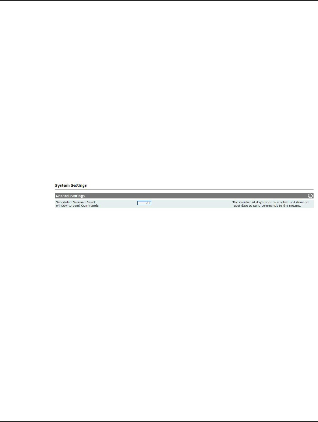
Draft
Chapter 6 - Scheduled Demand Reset Landis+Gyr
66 98-1723 Rev AB User Guide
Billing Cycle
•This approach is recommended when all meters in a billing cycle are required to reset
demand.
•Billing Cycle membership changes will NOT automatically be reflected in the next demand
resets.
Virtual Addressing Group
•This approach is recommended when not all meters in a billing cycle require a demand reset.
•Virtual Addressing Group membership changes will automatically be reflected in next
demand resets.
•This approach requires additional management (creating of virtual addressing groups,
manually adding meters to virtual addressing groups).
Sending the Demand Reset Commands
The System Setting Scheduled Demand Reset Window to send Commands (Figure 6 - 1) deter-
mines when the Demand Reset Schedule will be sent to endpoints. This value must be between 2-21
days and has a default value of 21 days. The value used for this setting is business decision made by
the utility to help ensure that meters are included in upcoming demand resets.
Figure 6 - 1. Scheduled Demand Reset Window to Send Commands
Whether or not newly added meters receive this schedule may depend on what type of group was
used for membership:
Billing Cycle Membership
•Meters added to the billing cycle after the commands have been sent to the meter will NOT
be included in the upcoming demand reset.
•Meters removed from the billing cycle after the commands have been sent to the meters will
still be included in the upcoming demand reset.
For example, if the Scheduled Demand Reset Window to send Commands is 5 days and:
The Demand Reset date for Billing Cycle 1 is scheduled for 11/10.
Scheduled Commands are sent on 11/5 to all meters in Billing Cycle 1.
A meter added to Billing Cycle 1 on 11/8 will not receive the schedule for 11/10.
Virtual Addressing Group
•Meters added to the Virtual Addressing Group after the commands have been sent to the
meter will be included in the upcoming demand reset.
•Meters removed from the Virtual Addressing Group after the commands have been sent to
the meters will not be included in the upcoming demand reset.
For example, if the Scheduled Demand Reset Window to send Commands is 5 days and:
The Demand Reset date for the Virtual Addressing Group is scheduled for 11/10.
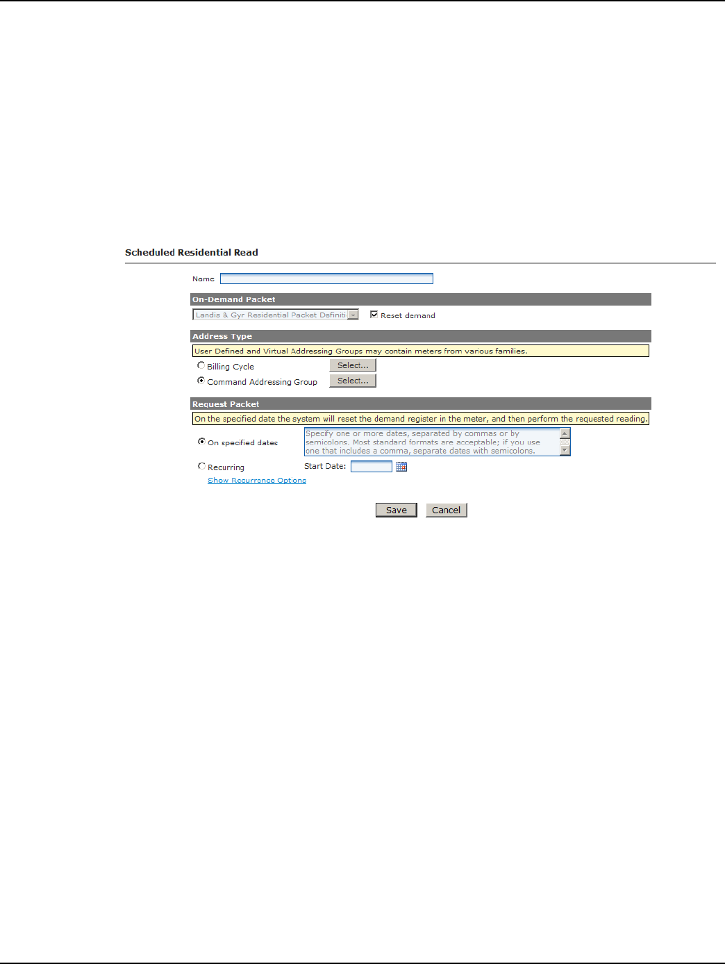
Draft
Landis+Gyr Chapter 6 - Scheduled Demand Reset
User Guide 98-1723 Rev AB 67
Scheduled Commands are sent on 11/5 to all meters in the Virtual Addressing Group.
A meter added to the Virtual Addressing Group on 11/8 will receive the schedule for 11/10.
Scheduled Read with Demand Reset
Following is the procedure for creating a Scheduled Read with Demand Reset.
1. Select Operations > Scheduled Reads > Cellular Residential. The Scheduled RF Residential
Reads window will open, displaying any future Scheduled Reads.
2. Click New. The Scheduled Residential Read window will open, shown in Figure 6 - 2.
Figure 6 - 2. Scheduled Residential Read
3. Name. Enter a name for the new scheduled read. The name must be unique to the organization.
4. Reset Demand. The Reset Demand check box must be selected to initiate the demand reset
process at the scheduled time. Once the Reset Demand check box is selected the On Demand
Packet drop down list will be grayed out. It is not necessary to select a packet to be transmitted.
5. Address Type. Select the desired Command Addressing Group(s) or select the desired Billing
Cycle.
6. Request Packet. Click On Specified dates to schedule the on-demand request for specific dates
in the future. Enter the specific date(s) in the text box separated by spaces, commas, or semi-
colons.
...or...
Click the Recurring radio button and enter a Start Date. If needed, click the Calendar icon to
generate a calendar from which to select a start date.
Click the Show Recurrence Options radio button to display recurrence choices.
• Do not repeat. The Scheduled Read will occur once.
• Repeat every [1-2-3-4] week(s) on Sunday through Saturday. The Scheduled Read
can be set to repeat every 1, 2, 3, or 4 weeks on any, or all, of the days of the week.

Draft
Chapter 6 - Scheduled Demand Reset Landis+Gyr
68 98-1723 Rev AB User Guide
• Repeat on day [] of each month. The Scheduled Read can be set to repeat on the same
date of each month. Enter a number from 1 to 31.
• Repeat [] day(s) before the end of each month. The Scheduled Read can be set to
repeat every month on a specified number of days before the last day of the month.
If repeating...
• Repeat until []. The Scheduled Read can be set to repeat until the user specified date by
clicking the calendar icon and selecting the end date for the Scheduled Read.
7. Click Save, to save the new Scheduled Read. The Scheduled RFU FocusAX Reads scheduled
will open, displaying the new scheduled read.
Changing/Deleting Schedules
A future schedule can be changed, deleted or copied on the main Scheduled Reads page.
Schedule Changes.
•If the temporary commands have already been sent down to the meter, Command Center
will issue commands to remove the original schedule from the endpoint.
•If the new schedule dates are within the next Scheduled Demand Reset Window to send
Commands (default 21 days), Command Center will send the schedule to the endpoint.
Schedule Deletes.
•If the temporary commands have already been sent, Command Center will issue commands
to remove the original schedule from the meter.
Scheduled Command Workflow Process
Once the Demand Reset is scheduled, X days before the Demand Reset date (X = Window to Send
Scheduled Commands) Command Center will issue a Send Scheduled Command command. The
Process Setting RF Scheduled Demand Reset Workflow dictates how frequently Command Center
will re-issue the Demand Reset commands to endpoints that have not acknowledged receipt of the
schedule. By default, this process runs every 30 minutes with a maximum number of retries equal to
5.
Monitoring Demand Resets
Command Center monitors two aspects of the demand reset process:
•Did the schedule reach the meters?
•Did the demand reset occur as scheduled?
Verifying Receipt of the Schedule
Individual verification that the Send Scheduled Command was issued and reached a designated
meter is visible on the individual Gridstream RF Endpoint Information - Manage tab. Group
verification of the receipt of the scheduled commands by designated meters can be done via the
Endpoint Report for Scheduled Reads with Demand Reset.
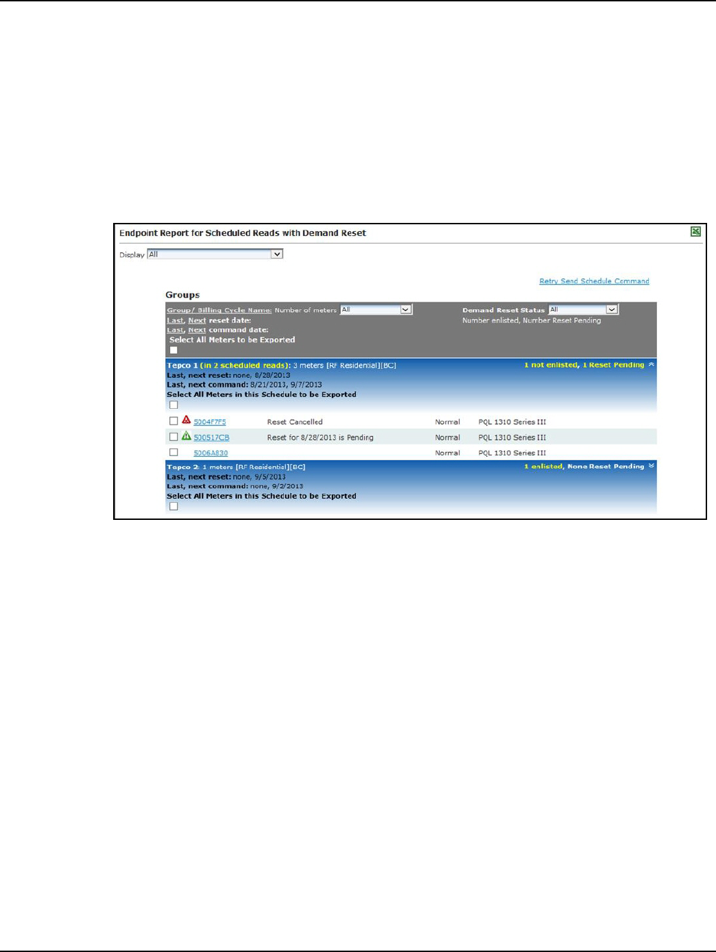
Draft
Landis+Gyr Chapter 6 - Scheduled Demand Reset
User Guide 98-1723 Rev AB 69
Endpoint Report for Scheduled Reads with Demand Resets
The Endpoint Report for Scheduled Reads with Demand Resets provides a list of all endpoints
scheduled for reset and the current status of the reset.
Following is the procedure for generating the Endpoint Report with Scheduled Demand Resets.
1. Select Operations > Scheduled Reads > RF Residential. The Scheduled Reads window will
open.
2. Click the Scheduled Demand Reset Status link. The Endpoint Report for Scheduled Reads
with Demand Resets window will open, shown in Figure 6 - 3.
Figure 6 - 3. Endpoint Report for Scheduled Reads with Demand Reset
The user can filter the report, by selecting a status from the Demand Reset Status drop down list.
The following information is displayed:
• User Defined Addressing Group. The report is filtered by User Defined Addressing
Group.
• Number Enlisted. This number indicates the total number of endpoints that are included in
the demand reset. Only those meters in Normal or Configure status can be enlisted.
• Last, Next Reset. This indicates the last time the endpoints were scheduled to be reset, and
when the next time the endpoints are scheduled to be reset.
• Last, Next Command. The last value indicates the last date the command was sent to the
meter. The next value indicates the next date the reset will be sent to the meter.
• Meter Number. Lists the meter numbers of those endpoints scheduled for rest. Click the
meter number hyper link to open the Endpoint Information screen.
• Reset Status. See Table 6-1, “Demand Reset Status - Legend.” for description of Demand
Reset Status
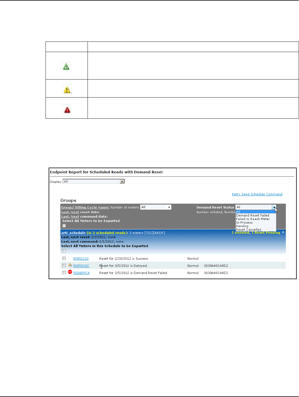
Draft
Chapter 6 - Scheduled Demand Reset Landis+Gyr
70 98-1723 Rev AB User Guide
• Meter Status. Meter status shows the current status of the endpoint (Installed, Discovered,
Normal, Lost).
The meters displayed in the Endpoint Report for Scheduled Reads with Demand Reset may be
exported:
3. Select the Select Meters to be Exported check box.
4. Select the check box next to the meters to be exported, as shown in Figure 6 - 4.
Figure 6 - 4. Endpoint Report for Scheduled Reads with Demand Reset
Retrying a Scheduled Command
In the event that network connectivity issues prevented the schedule from reaching the meter and the
connectivity issues have been resolved, the schedule may be reissued from this report. The user may
easily resend the demand reset schedule command to meters that have not received it by selecting the
Retry Scheduled Command link.
The Endpoint Report for Scheduled Demand Resets report will refresh to display only those
meters that have failed to receive the command with check boxes, to allow the user to select those
meters that the command should be sent to.
If the meter is reachable, the meter's scheduled demand reset status would transition to Pending. If
the meter is still unreachable, the status will be unchanged
Table 6-1. Demand Reset Status - Legend
Symbol Description
Green Caution Sign - Pending - The endpoint has successfully heard the demand reset
commands. Includes all endpoints that are in the process of being reset, but have not yet
successfully returned a confirmation event and are within the 24 hour window.
Yellow Caution Sign - Command Center is in the process of sending the demand reset
schedule to devices
Red Caution Sign - Demand reset schedule failed to reach the meter
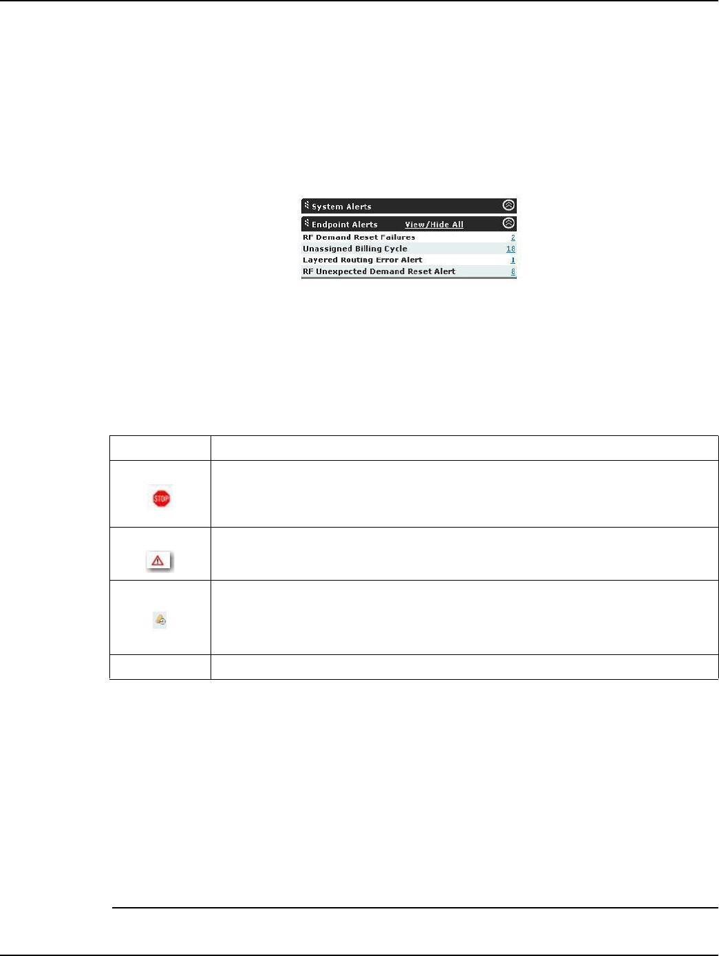
Draft
Landis+Gyr Chapter 6 - Scheduled Demand Reset
User Guide 98-1723 Rev AB 71
Verifying the Demand Reset
Process Setting: The Confirm RF Demand Reset Process Setting monitors the meters that are
expected to reset demand. The default frequency is every 4 hours.
If the Demand Reset packet has not been received within the first four hours of the demand reset day,
Command Center will send a request for the Demand Reset Data packet. At the end of the day, if
Command Center has not received the demand reset data, an RF Demand Reset Failure event will
be displayed on the AMI Dashboard as shown in Figure 6 - 5.
Figure 6 - 5. AMI Dashboard - Endpoints
This alert will remain on the AMI Dashboard until the next successful scheduled demand reset.
The Endpoint Report for Scheduled Reads with Demand Resets report may also be used to mon-
itor the success or failure of demand resets. See Table 6-2, the color-coded icons provide an indica-
tion of the status of demand resets.
Failure to get a Demand Reset event may result from the following conditions:
•The endpoint did not receive the command. Command Center will attempt to send the
schedule demand reset command to the endpoint five times by default. If unsuccessful, the
endpoint demand reset status will be changed to failed.
•The endpoint received the command but the reset failed
•The demand reset occurred and the data was sent but the data was not received by Command
Center.
After a failure has been recorded, the user must manually retry the demand reset. The manual retry
may be performed point to point for an individual endpoint, or may be group addressed.
NOTE: If there are future Demand Reset dates scheduled for the meter, Command Center will
Table 6-2. Demand Reset Status - Legend
Symbol Description
Red Stop Sign - Demand reset failed to occur as scheduled. Includes all endpoints that
did not successfully reset their demand within the 24 hour window.
White Yield Sign - Demand Reset occurred as scheduled.
Yellow Sign with Clock - The endpoint has not successfully reported demand reset data
and is within the 24 hour window. This will be displayed only after a device has
transitioned to Pending, and will precede either a Scheduled Demand Reset Success or a
Scheduled Demand Reset Failure status.
No Symbol - Indicates the endpoint has successfully reset demand
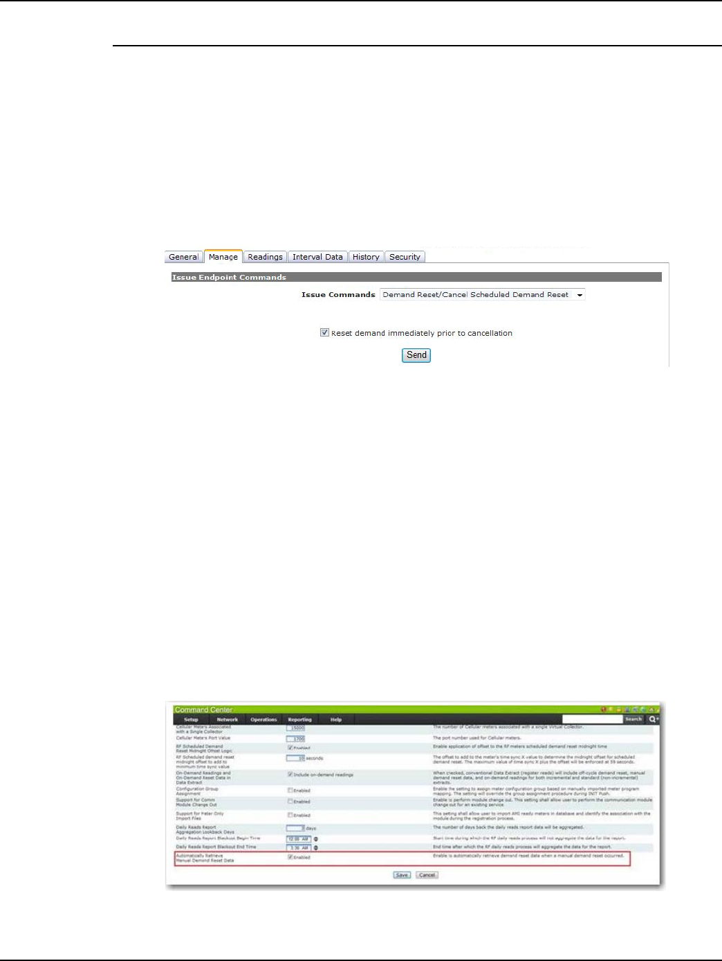
Draft
Chapter 6 - Scheduled Demand Reset Landis+Gyr
72 98-1723 Rev AB User Guide
schedule the next reset (during its normal process), regardless of a past Demand Reset failure.
Canceling a Demand Reset
A Scheduled Demand Reset may be canceled point to point or group based. Following is the proce-
dure to cancel a Scheduled Demand Reset, point to point:
1. From the Gridstream RF Endpoint Information screen, select the Manage tab.
2. From the Command to Issue drop down box, select Demand Reset/Cancel Demand Reset.
The screen will refresh to display demand reset options check box, as shown in shown in Figure
6 - 6.
Figure 6 - 6. Gridstream RF Endpoint Information - Manage Tab
3. Select the Reset demand immediately prior to cancellation to perform a demand reset, and
cancel the scheduled demand reset. De-select the check-box to simply cancel the demand reset.
4. Click the Send button to issue the command.
The Demand Reset/Cancel Demand Reset command may also be issued to Virtual Addressing
Groups via Network > Endpoints > RF Electric Grp Cmds.
Unexpected Demand Reset
When demand is reset at a meter in the field, an Unexpected Demand Reset event occurs and is sent
to Command Center. An AMI Dashboard alert of the same name will reflect the number of events
that have occurred.
SystemSetting: The System Setting Automatically Retrieve Manual Demand Reset Data allows
the utility to read demand reset data from the meter when Command Center receives an Unexpected
Demand Reset.
Figure 6 - 7. Unexpected Demand Reset

Draft
User Guide 98-1723 Rev AB 73
7
Specifications
Specifications
Radio
3G
•3G meets the requirements of 3GPP release 5
Table 7-1. Cellular
Cellular
Max Output Power 3G* 24dBm +1/-3
Transmit Frequency 3G Band II
Band V
1850-1910 MHz
824-849 MHz
Receive Sensitivity 3G Band II
Band V
-107dBm
-108dBm
*Meets requirement of 3GPP release 5
Table 7-2. Electrical
Electrical
Voltage 12 - 24V (From meter power supply)
Power Max 2.0W
Typical 0.8W

Draft
Chapter 7 - Specifications Landis+Gyr
74 98-1723 Rev AB User Guide
ZigBee Transmit Power and Receive Sensitivity
Table 7-3. ZigBee Radio General
Parameter
Value
Units Comments
Min Typ Max
RF Frequency Range 2.405 2.475 GHz
No. of Channels 15
Modulation Type O-QPSK Comply with IEEE 802.15.4
Data rate 250 kbps
IEEE Specification 802.15.4
On air Tx time (duty cycle) 66 % 66ms per 100ms max (per Ember)
Memory
RAM
Flash
12
192
KB
Antenna type Inverted F Printed
Peak antenna gain -3.07 dBi Peak gain
Antenna polarization vertical
Table 7-4. ZigBee Transmitter
Parameter
Value
Units Comments
Min Typ Max
Output power (conducted) 19 dBm Measured at room temp.
Frequency stability -40 +40 ppm
Error vector magnitude 5 30 %
Power Spectral Density/3kHz BW 6 dBm
6 dB Bandwidth 1.59 MHz Modulated
Table 7-5. ZigBee Receiver
Parameter
Value
Units Comments
Min Typ Max
Sensitivity -104 -101 dBm At 35% PER
Adjacent Channel Rejection 40 dBc
Image Rejection 30 dB Per Ember

Draft
Landis+Gyr Chapter 7 - Specifications
User Guide 98-1723 Rev AB 75
Environmental
Mechanical
Regulatory Compliance
Table 7-6. Environmental Specifications
Parameter Min Max Units Notes
Storage temperature -40 85 °C
Operating Temperature -40 70 °C
Relative Humidity 0 95 % Non-condensing
Table 7-7.
Parameter Value
Size 2.6 W x 5.6 L x 1.16 H inches, typical (excluding antenna)
Weight 2.4 ounces typical
Table 7-8. Regulatory Compliance
Parameter Comments
Cellular Radio Meets Sierra Wireless design criteria in order to use the
FCC ID of their existing modular approval.
ZigBee Radio FCC CFR Title 47, part 15.247
Conducted Emissions ANSI C12.1-2008 section 4.7.3.13 Test 27
FCC CFR Title 47, part 15 subpart A and B, class B
Radiated Emissions ANSI C12.1-2008 section 4.7.3.13 Test 27
FCC CFR Title 47, part 15 subpart A and B, class B
Electrostatic Discharge Immunity ANSI C12.1-2008 section 4.7.3.14 Test 28
IEC 61000-4-2 Level 4
Radiated RF Electromagnetic Field Immunity ANSI C12.1-2008 section 4.7.3.12 Test 26
IEC 61000-4-3 Level x (15V/m)
Electrical Fast Transient/Burst Immunity
ANSI C12.1-2008 section 4.7.3.11 Test 25
IEC 61000-4-4 Level 4
Additional requirement of 4.4kV test voltage
Surge Immunity (Combination Wave)
ANSI C12.1-2008 section 4.7.3.3 Test 17
IEEE C62.41.2-2002 Category B
IEC 61000-4-5 Level x (6kV)
Surge Immunity (100 kHz Ring Wave)
ANSI C12.1-2008 section 4.7.3.3 Test 17
IEEE C62.41.2-2002 Category B
IEC 61000-4-12 Level x (6kV)
Surge Immunity (1 MHz Oscillatory)
ANSI C12.1-2008 section 4.7.3.11a Test 25a
IEEE C37.90.1-2002
IEC 61000-4-18 Level 3

Draft
Chapter 7 - Specifications Landis+Gyr
76 98-1723 Rev AB User Guide
Environmental, Health and Safety
This product is designed and constructed so that no safety hazard will occur to people or the environ-
ment when correctly installed and with normal use.
Customer Service
Contact Landis+Gyr Customer Support at solutionsupport.na@landisgyr.com or call 888-390-5733
with any questions or problems, and they will guide you through the troubleshooting process.
10 kV Surge Immunity ±10kV Combination Wave, 10 strikes @ 90° from L1 to L2
Voltage Dips and Interrupts Immunity ANSI C12.1-2008 section 4.7.3.2 Test 16
IEC 61000-4-11 Level 0, 40, and 70
Mechanical shock ANSI C12.1-2008 section 4.7.3.18 Test 32
IEC 60068-2-27: 1987
Mechanical Vibration ANSI C12.1-2008 section 4.7.3.20 Test 34
IEC 60068-2-6: 1987
Accelerated Life Test
For expected life of 10 years:
82°C with 85% Relative Humidity
650 Hours - Fully functional
IPC A-610D:2005 Acceptability of Electronic Assemblies
Table 7-8. Regulatory Compliance (Continued)
Parameter Comments