Landis Gyr Technology GRAMCNLX1 GasLX Residential American User Manual Installation Guide
Landis+Gyr Technology, Inc. GasLX Residential American Installation Guide
UserManual.wiki
>
Landis Gyr Technology
>
GRAMCNLX1 User Manual
Installation Guide
Navigation menu
Upload a User Manual
Namespaces
Wiki Guide
HTML
PDF
Info
Views
User Manual
Discussion / Help
Navigation


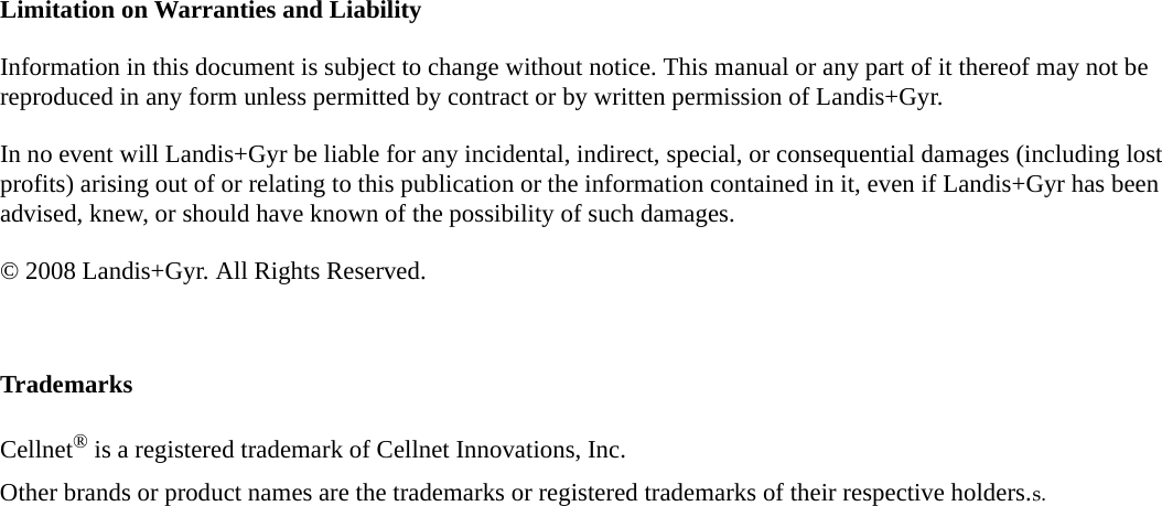


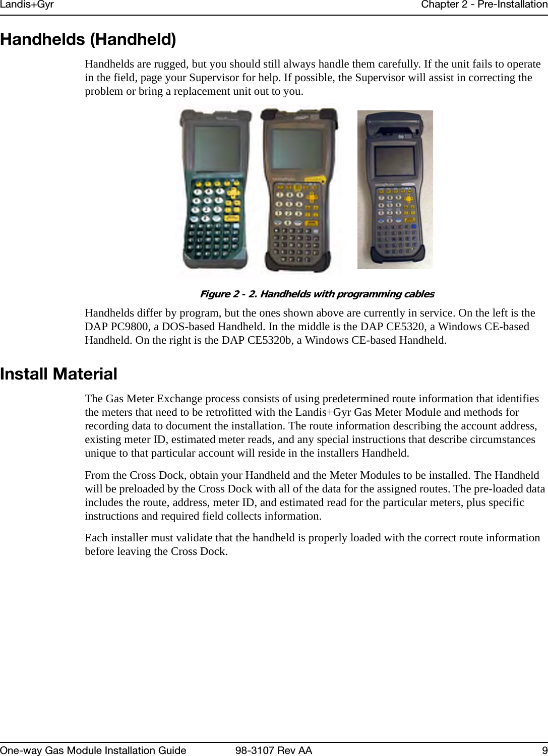

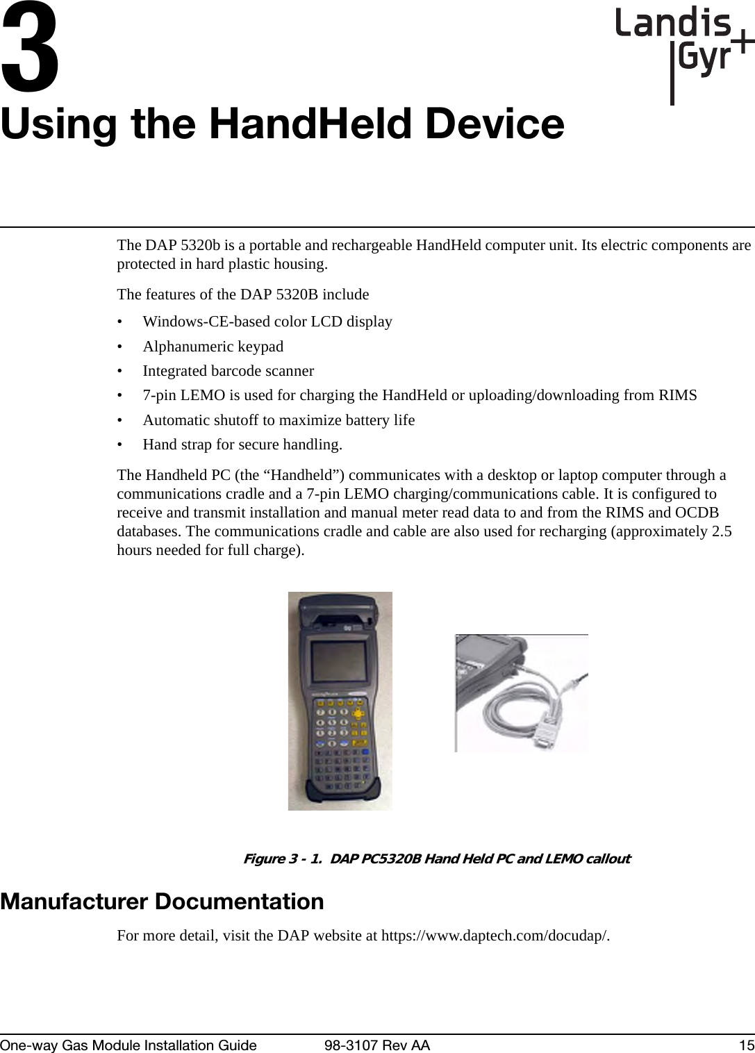
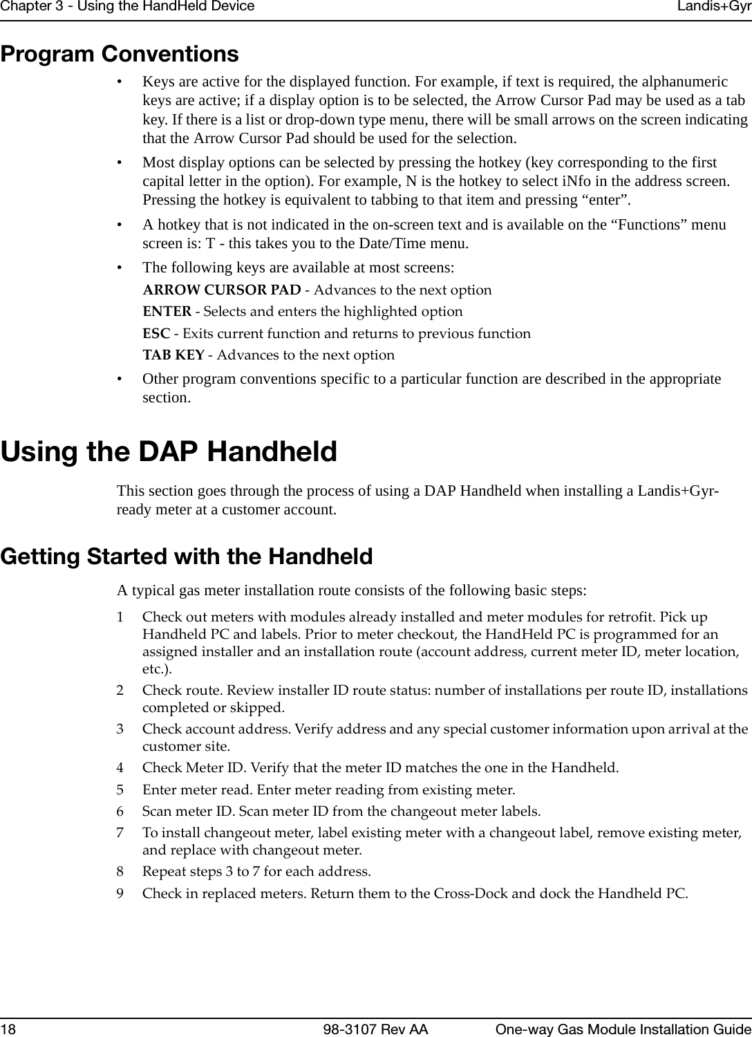
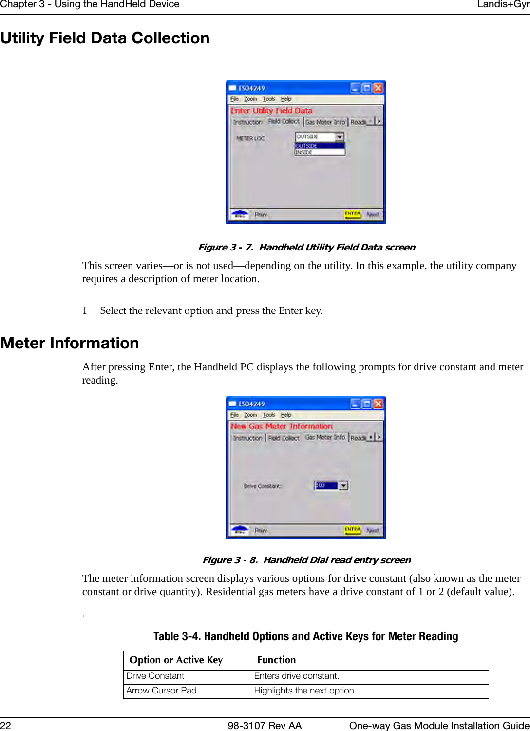
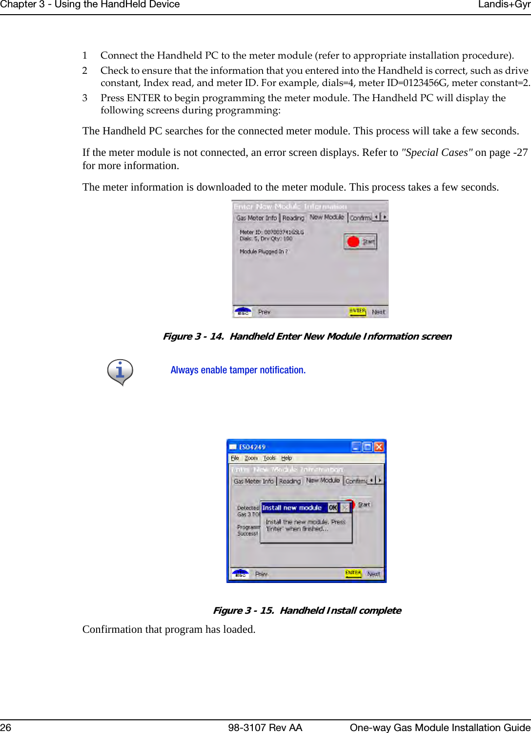
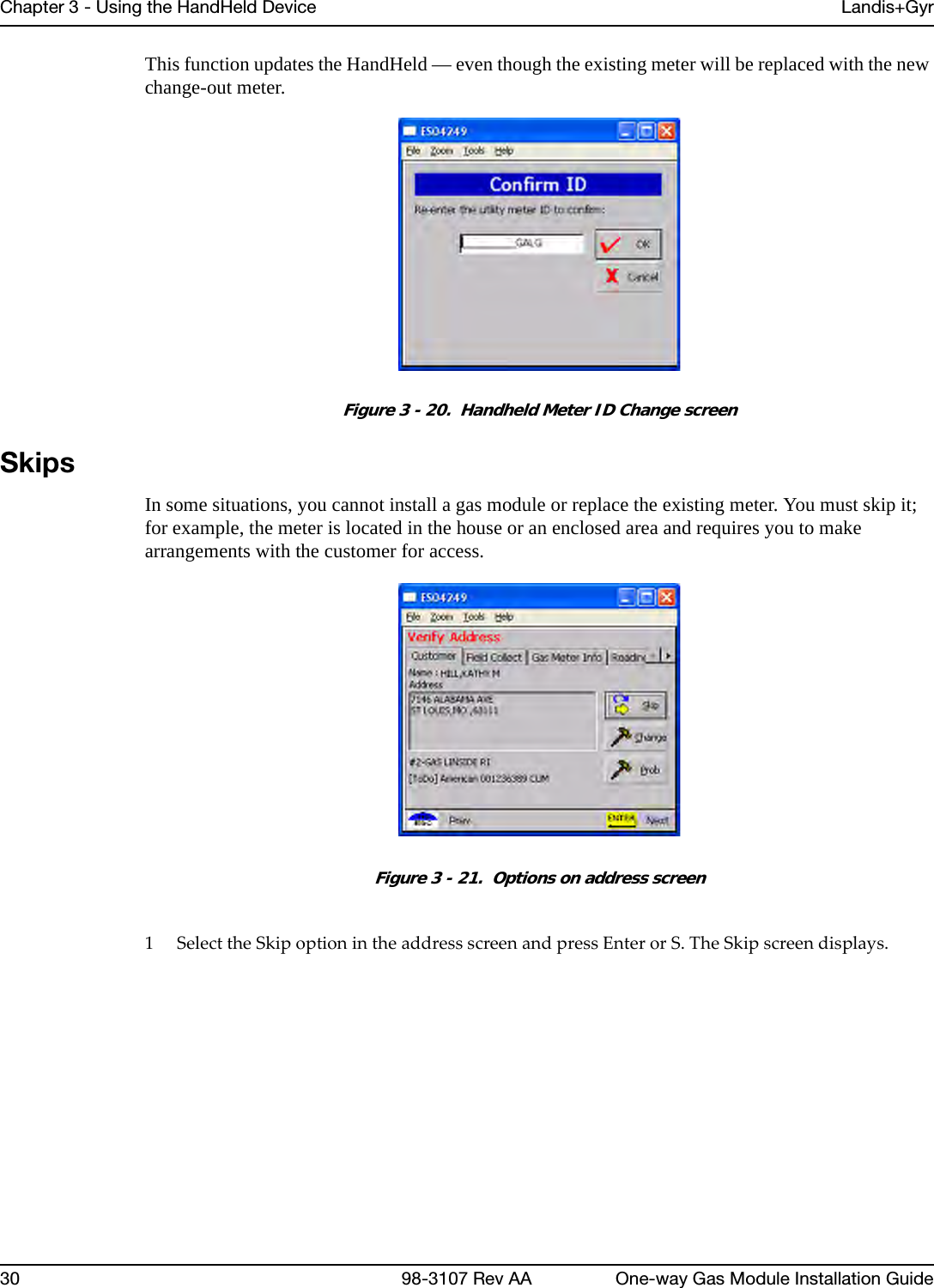
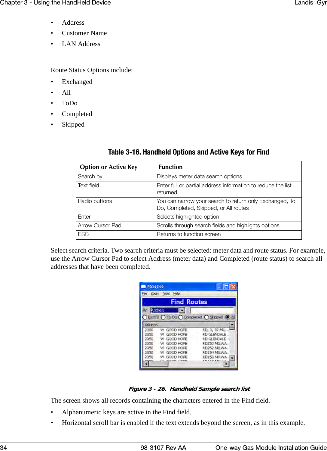
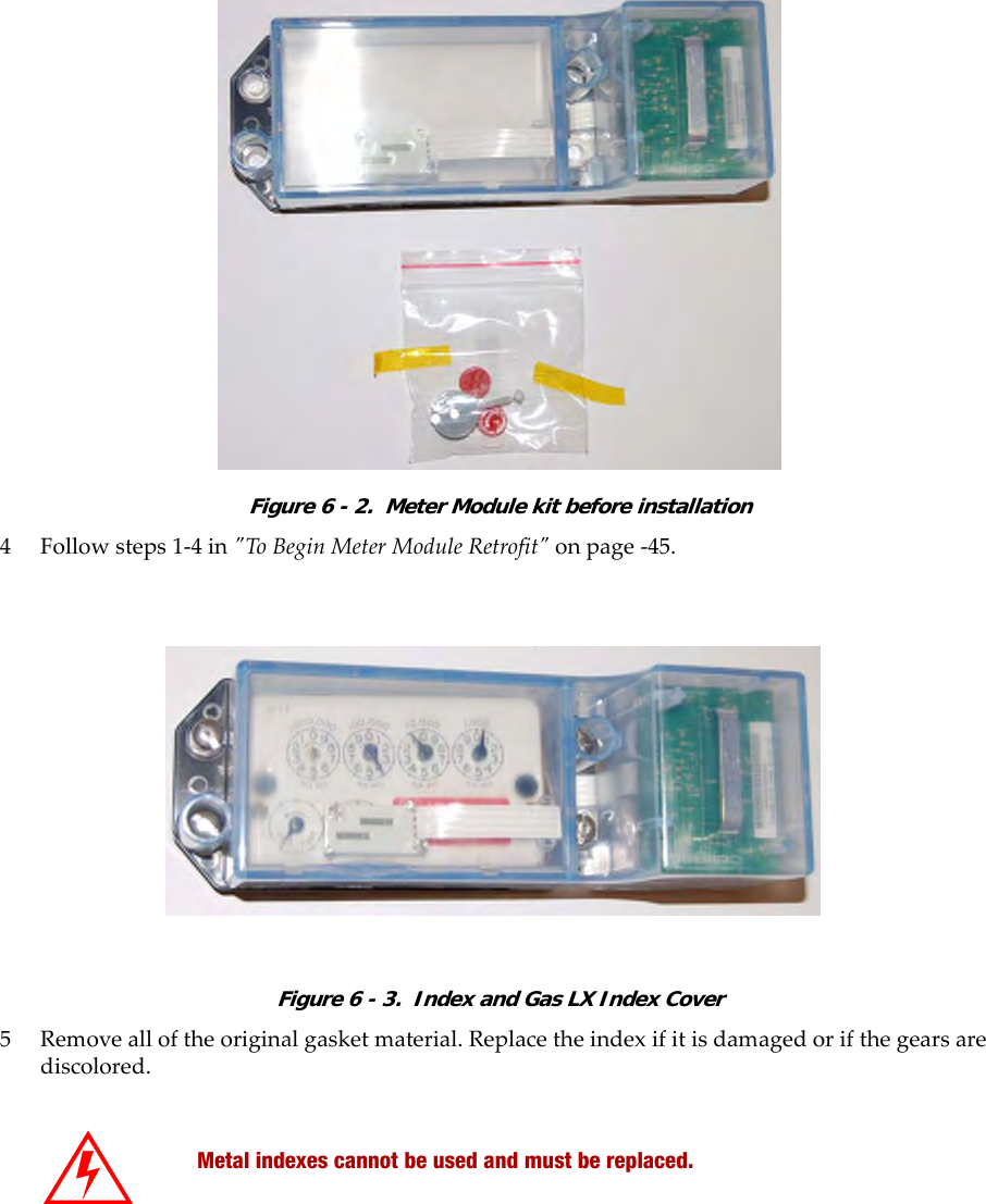
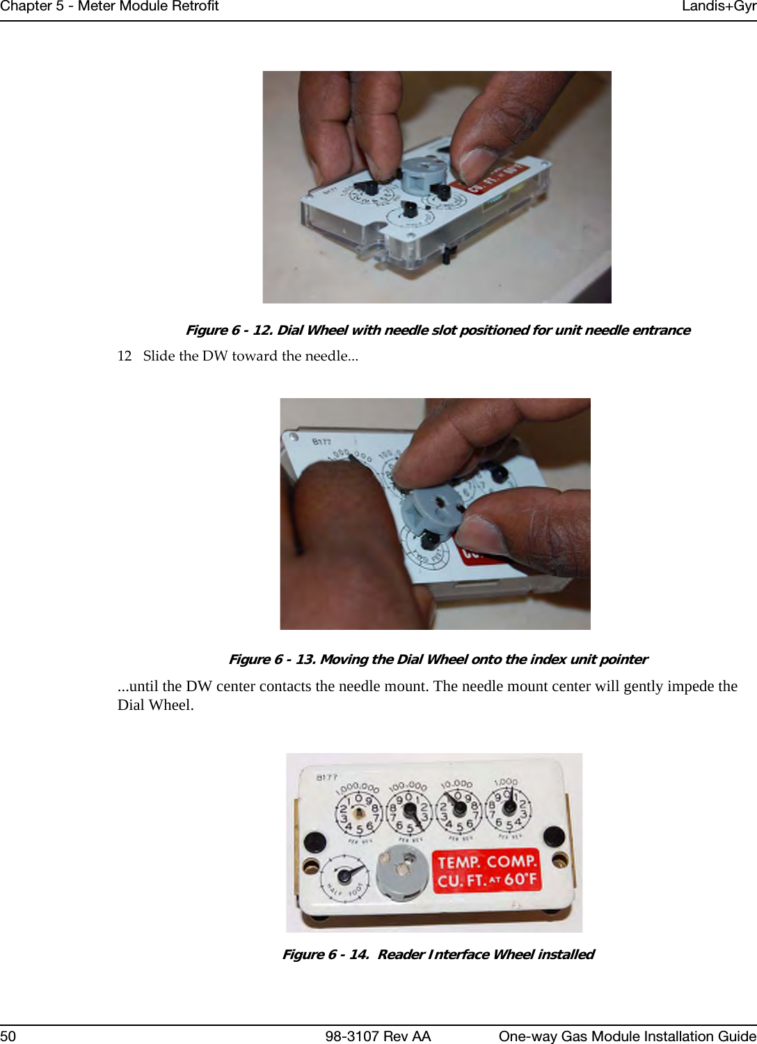
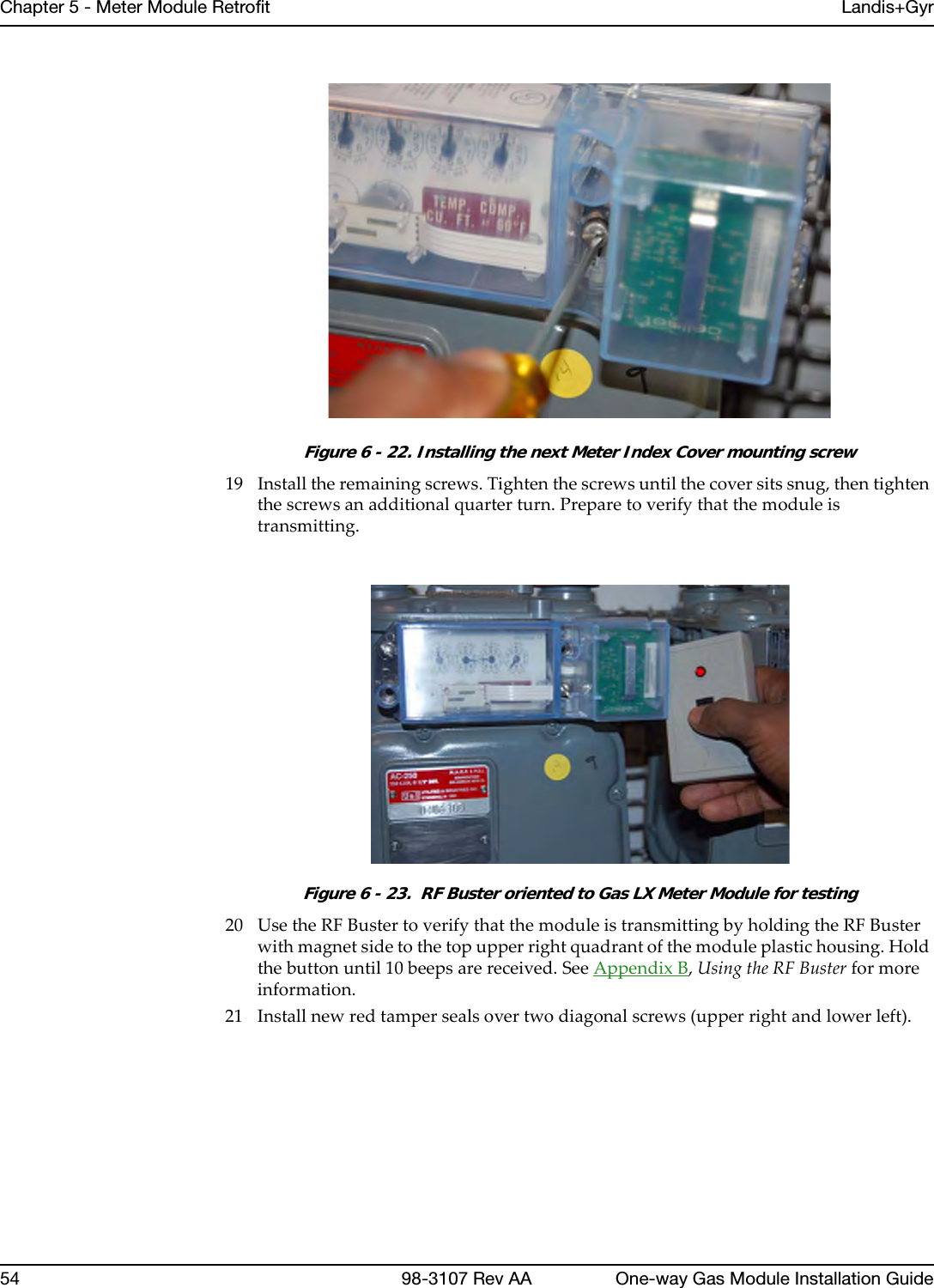

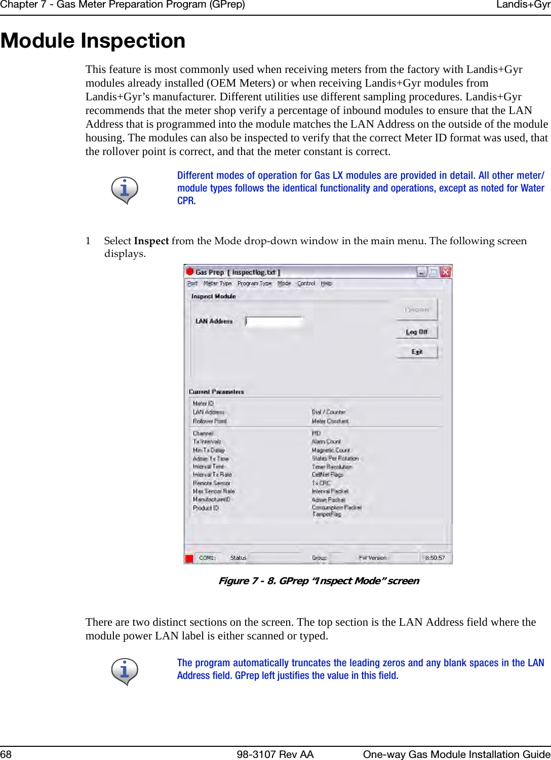
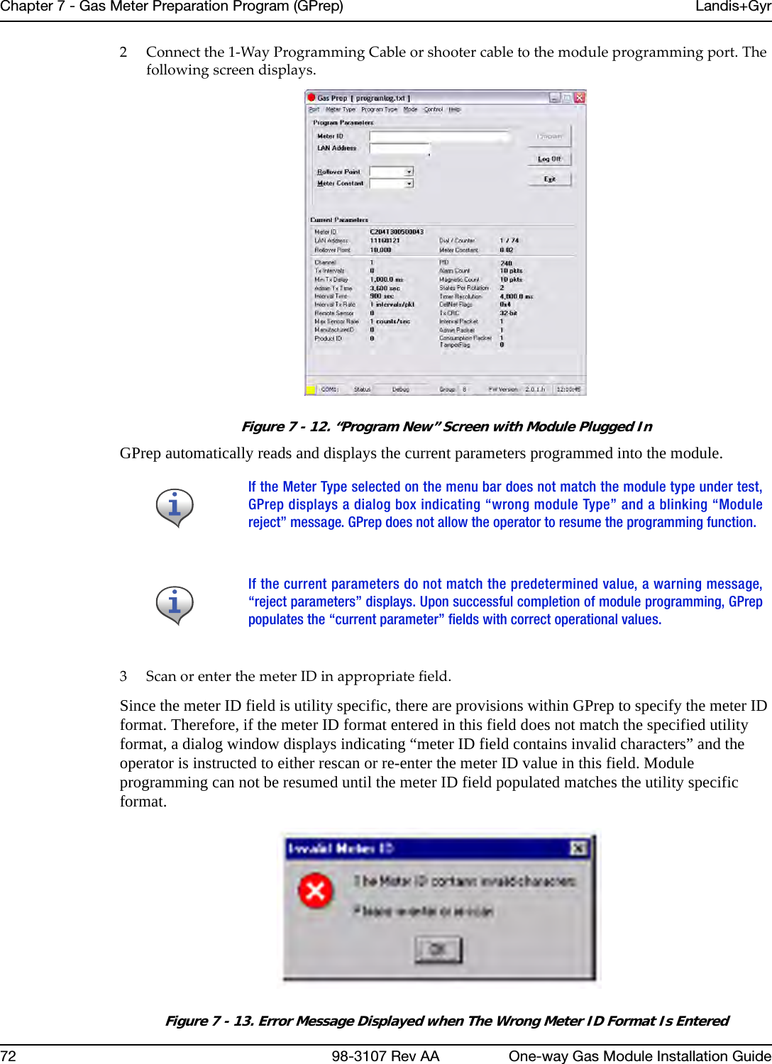
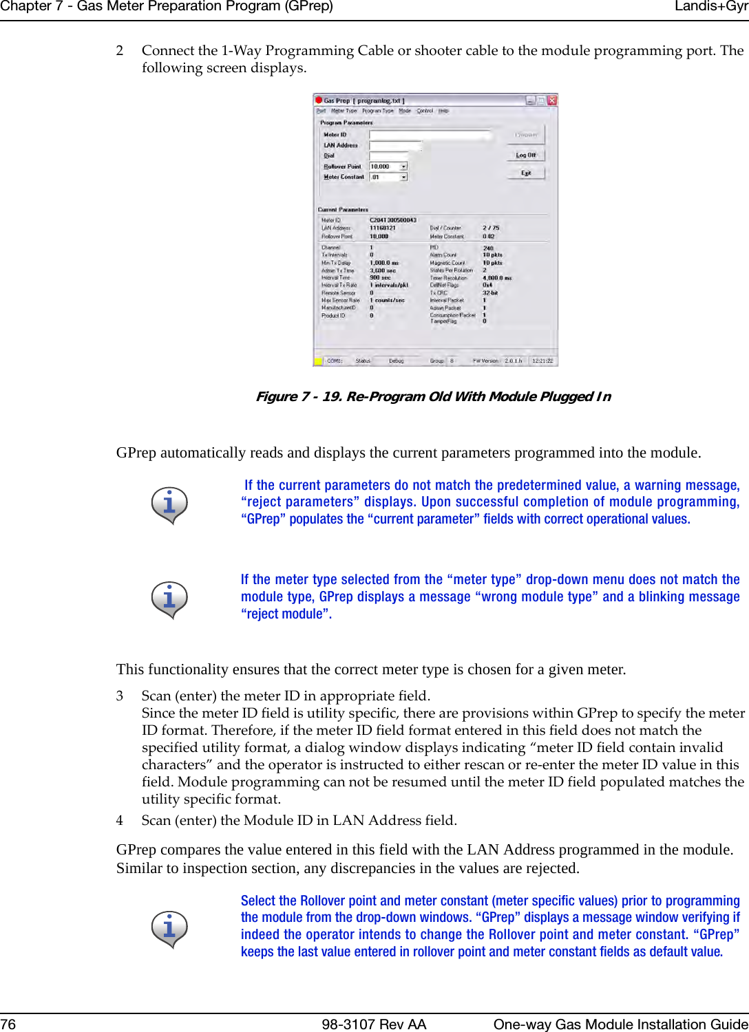
![Chapter 7 - Gas Meter Preparation Program (GPrep) Landis+Gyr58 98-3107 Rev AA One-way Gas Module Installation GuideRequired ToolsThe following is a list of required tools to operate GPrep, along with a PC / operating system recommendation:• Desktop PC with Windows 2000 or higher (Windows NT is not recommended when using a laptop computer since there are sometimes problems configuring the ports)• Copy of GPrep v. 2.3 or most recent version on a required tools CD• Shooter Box with AC power cord, part number 26-3500 and gas shooter cableor 1-Way Module Programming Cable PN 26-1179• Battery, part number 40-1032 or 40-1590•Laptop/PC • DB9 to DB9 cable (male on one end female on the other) straight through (RS232).Roles•GPrep Administrator - is the local expert on GPrep. The Administrator is familiar with the entire functionality of GPrep. The Administrator knows how to configure all internal files, and how to grant certain permissions.The Administrator knows how to clean all files of bad records and supersedes. How to archive all files and e-mail them to the appropriate database administrator or RIMS analyst and how to train the day to day users of GPrep. This person has the daily task of maintaining GPrep and its files.•GPrep User - needs to know the fundamentals of GPrep. They need to know how to log in, how to marry a meter with a module, and how to inspect a module to ensure that it is properly programmed, and what to do if it is not.Procedures for GPrep Administrator1Verifyyourtools.GPrepdoesnotoperatewithoutallofthetoolslistedintheRequiredToolssection.2UnzipGPrepfilestoyourPCorlaptop.aCustomizeGPrep.TheGPrepinstallationfoldercontainsafilenamedGPREP.INI.Thisfiledefinesallconfigurationparametersinits[Control]sectionandmaintainssettingsfromthelastGPrepruninits[Default]section.•Ifthisisanewinstallation,GPREP.INImustbecopiedtotheGPrepinstallationdirectory.•Ifthisisanupgrade,thenyoucanusetheexistingGPREP.INIfiletomodifyanyconfigurationparametersasnecessary.b EdittheGPREP.INIfileusingNotepadoryourpreferredASCIIfileeditor.Before copying files go to “View” on the menu bar of your PC, select “FolderOptions”. Under a section titled “Advanced Settings” there is a folder called“Hidden files”, under that folder choose “show all files”, then click on the OKbutton.](https://usermanual.wiki/Landis-Gyr-Technology/GRAMCNLX1/User-Guide-1057800-Page-63.png)
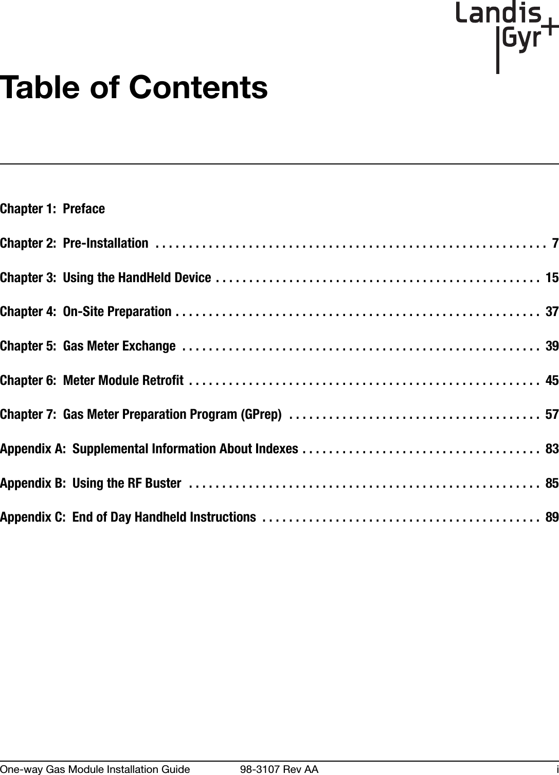
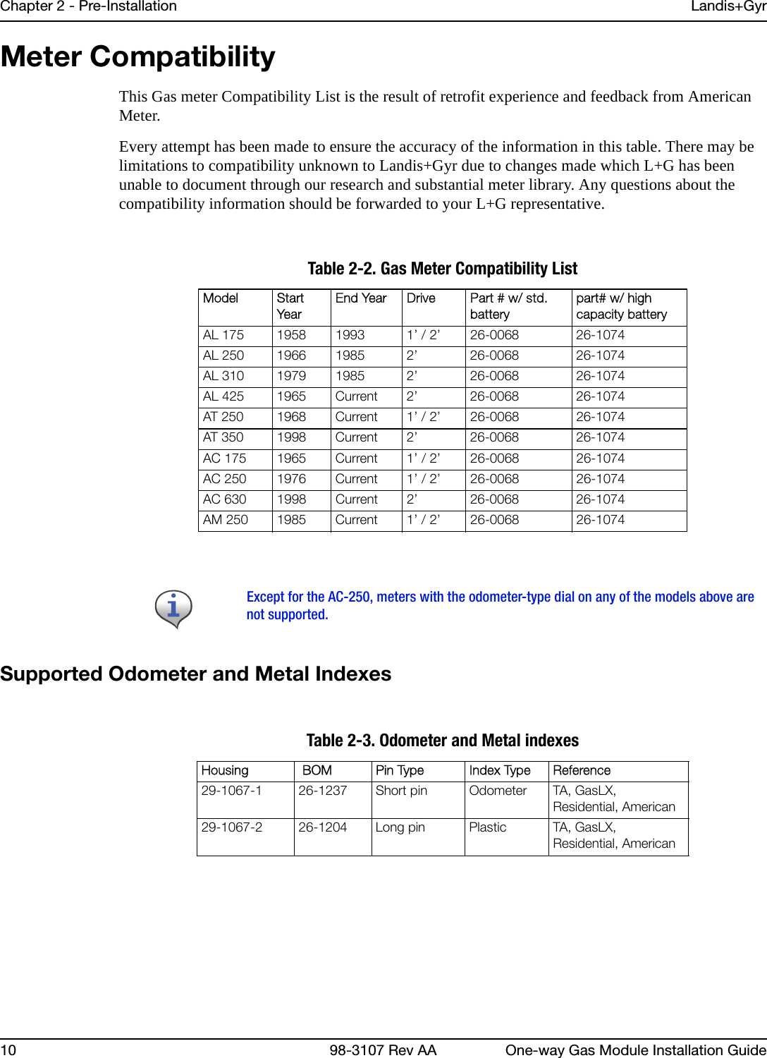
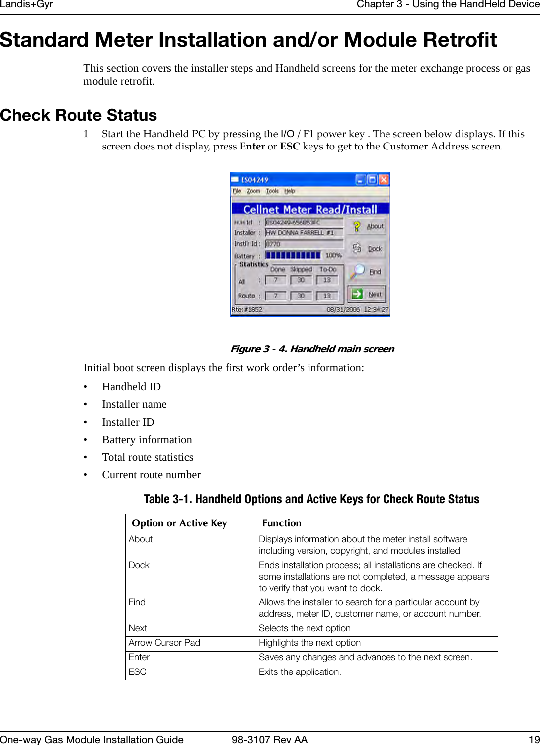
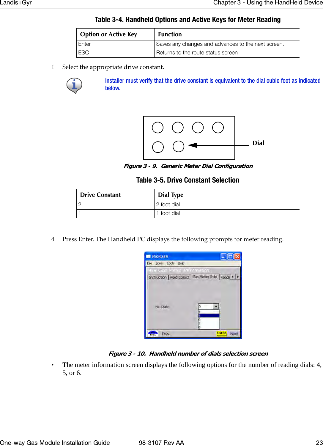
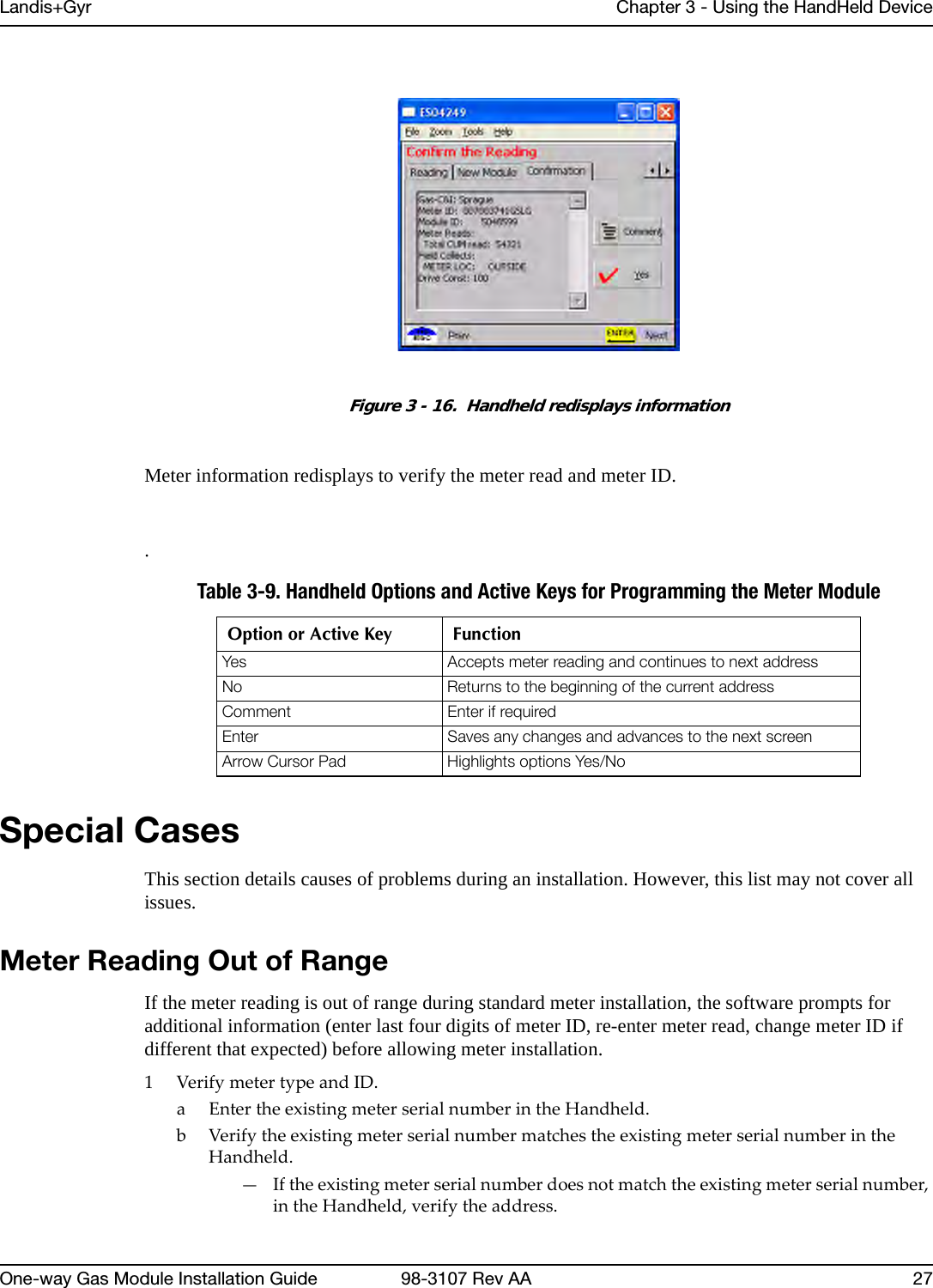
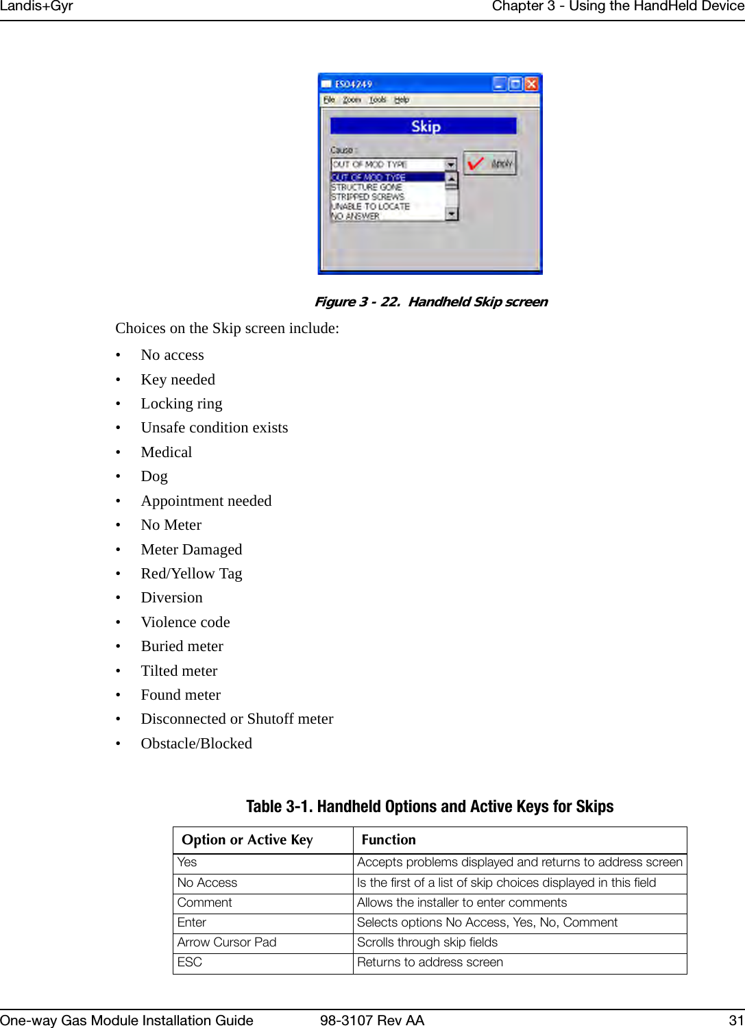
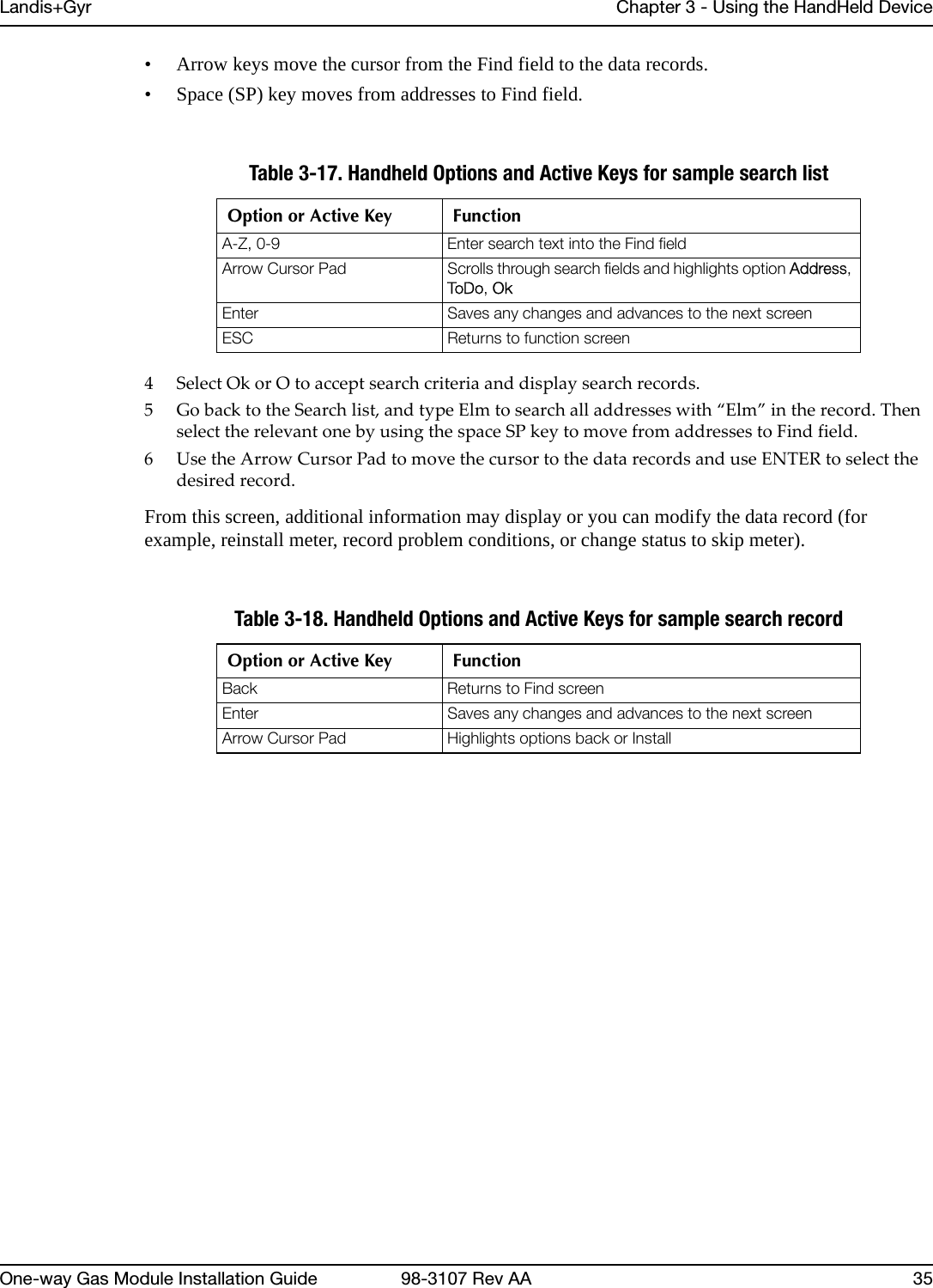
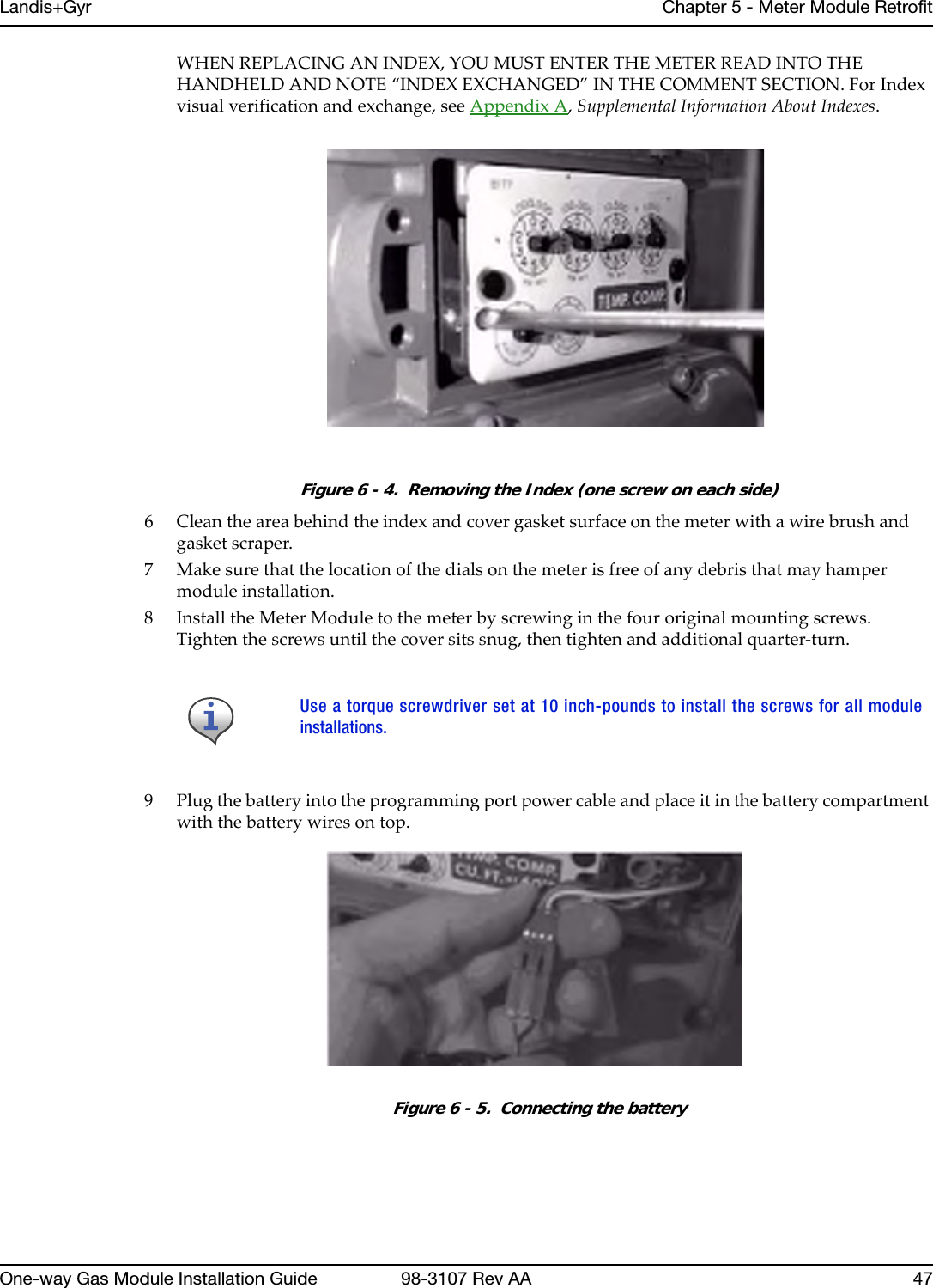
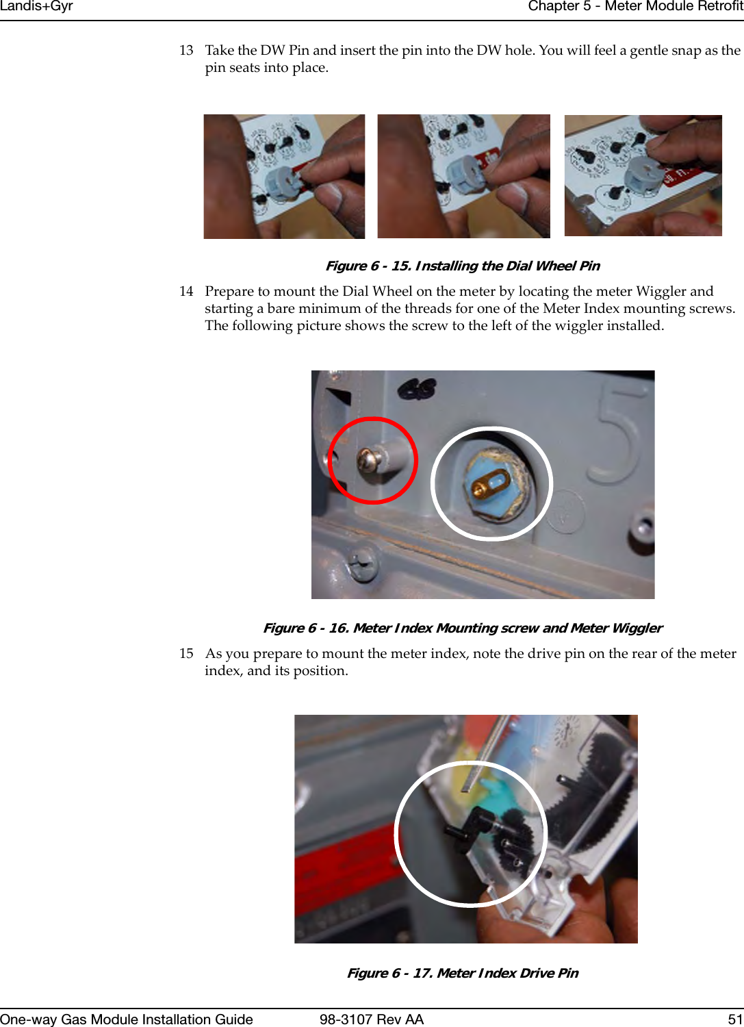
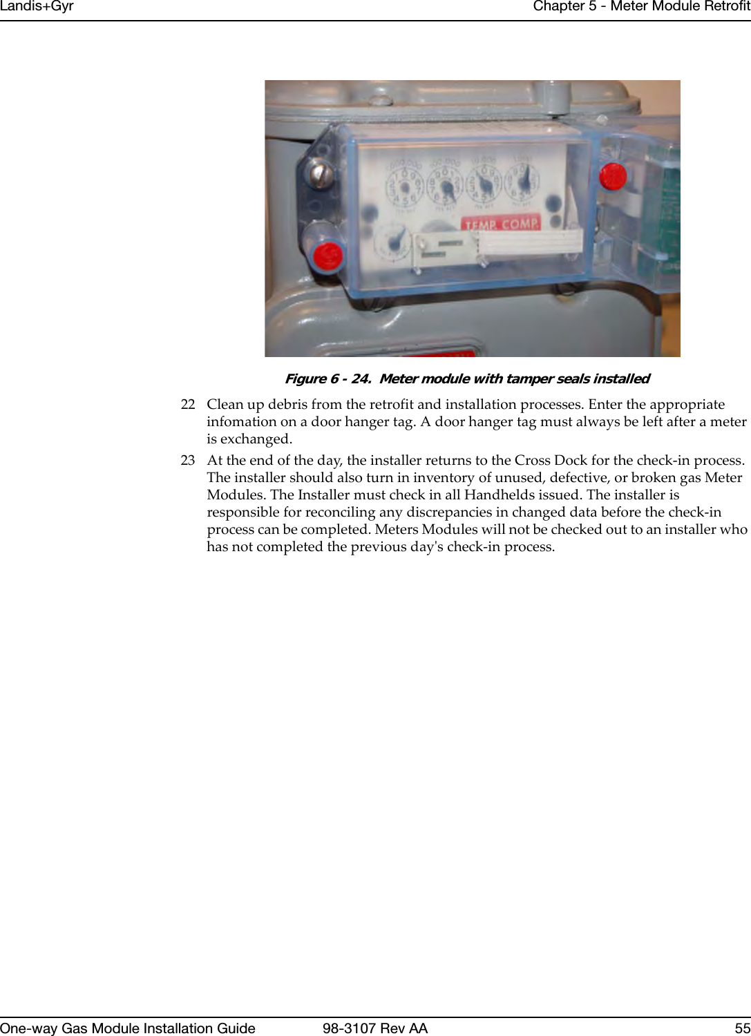
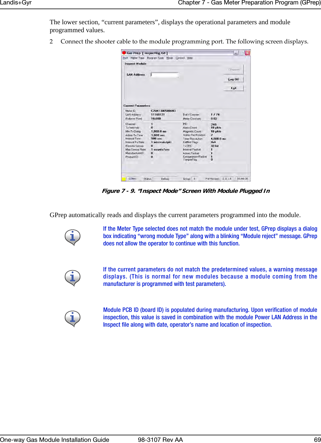
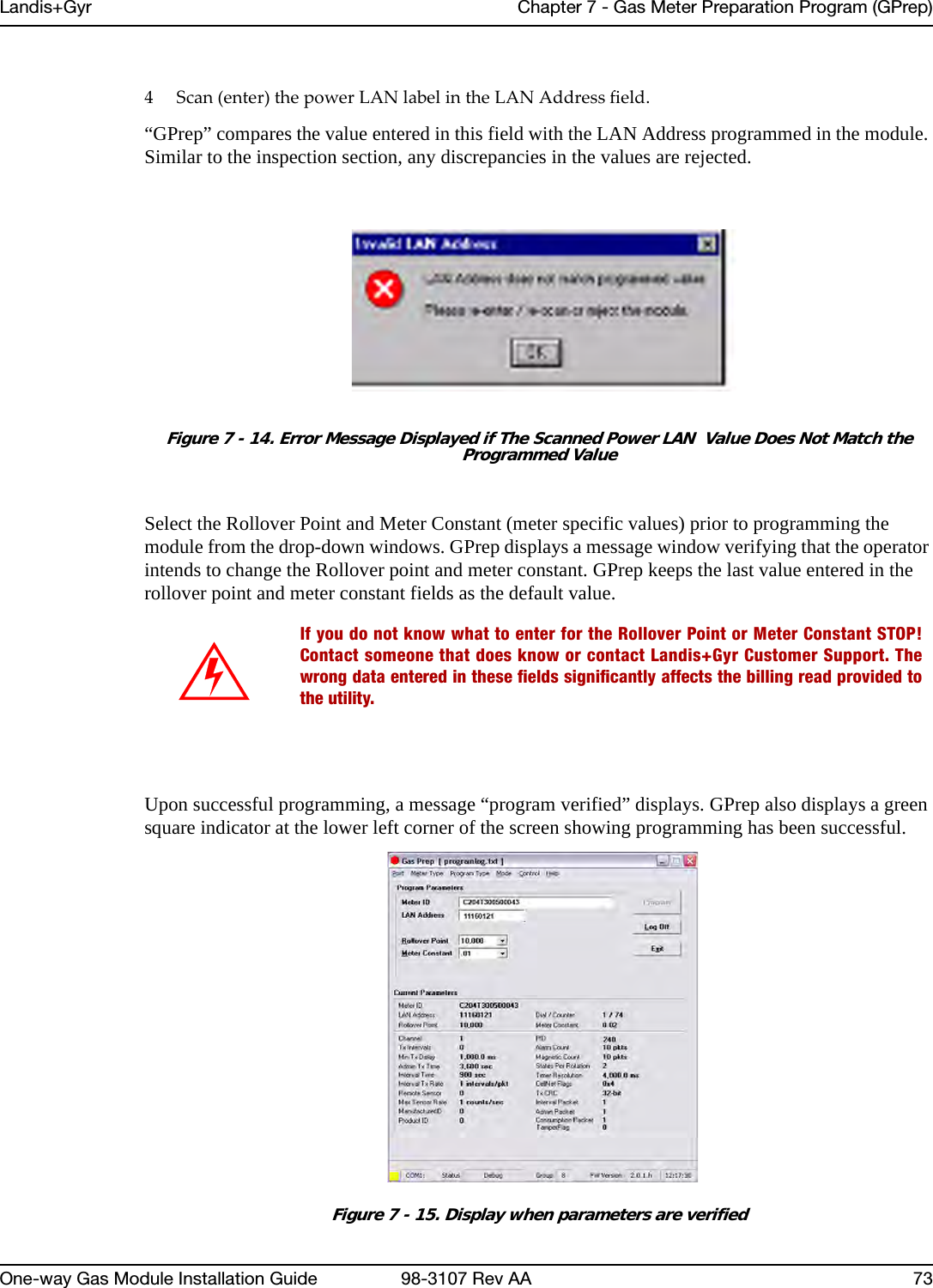
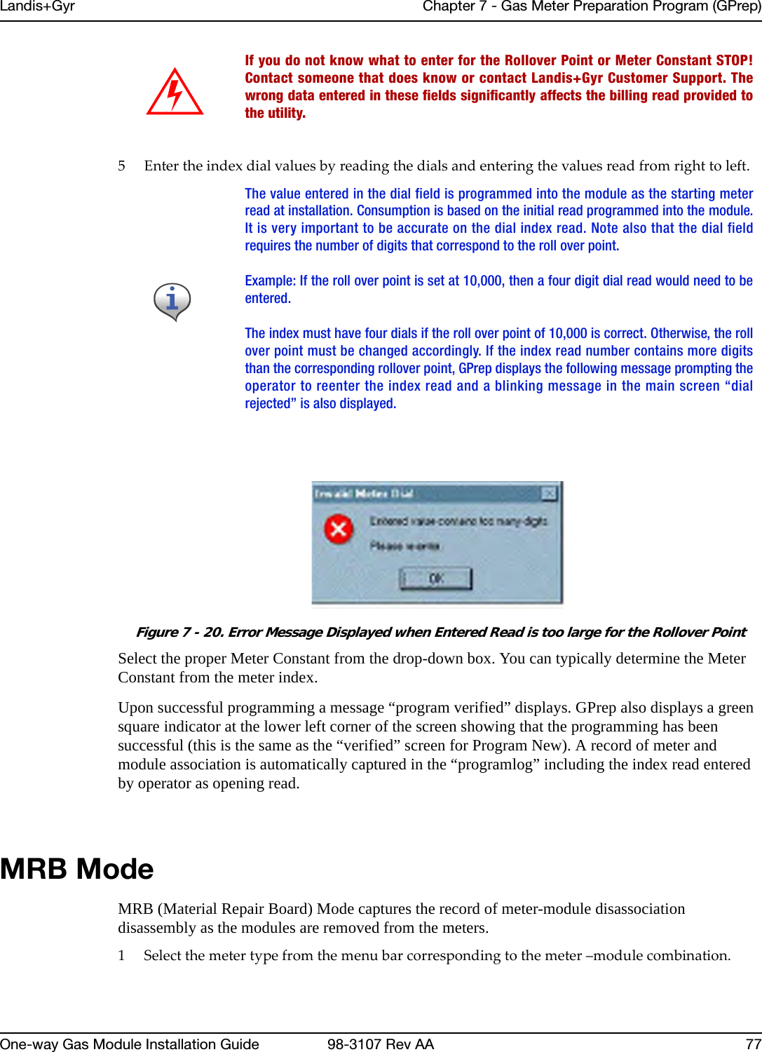
![Landis+Gyr Chapter 7 - Gas Meter Preparation Program (GPrep)One-way Gas Module Installation Guide 98-3107 Rev AA 59c FollowtheinstructionsinthatfiletospecifytherequiredpatternforMeterIDs,file(s)forloggingoperations,menuselectionsthatareavailabletotheoperatorandthemaximummemoryusedtotrackpreviouslogfileassociations.Following is an example of a GPREP.INI file.; The Default section remembers GPrep settings from the last run. These should; not be changed manually.; ------------------------------------------------------------------------------[Default]; The Control section contains GPrep operational parameters.; ------------------------------------------------------------------------------; Operator Meter Type selections are controled by variables:;; RGAS for ResGas; CIGD for C&I Gas (Diaphragm); CIGR for C&I Gas (Rotary); CPRG for CPR Gas (Rotary);; Setting any of these to "No" disables the menu item. The default is "Yes".;; Example:; RGAS=No; CIGR=Yes; Disables "ResGas" selection, leaving both C&I and CPR selections enabled.; ------------------------------------------------------------------------------; Operator Mode selections are controled by variables:;; Inspect; ProgramNew; ProgramOld; IndexRead; MRBMode;; Setting any of these to "No" disables the menu item. The default is "Yes".;; Example:; ProgramOld=No; Inspect=Yes; MRBMode=No; Disables "Re-Program Old" and "MRB" selections, leaving "Inspect",; "Program New" and "Index Read" modes enabled.; ------------------------------------------------------------------------------; Operator Port selections are controled by variables:;; COM1, COM2, COM3 and COM4;; Setting any of these to "No" disables the menu item. The default is "Yes".;; Example:; COM4=No; COM3=NoIf you run GPrep in different modes and/or it requires different configuration settings at thesame operator station, then install multiple copies of GPrep in different directories.](https://usermanual.wiki/Landis-Gyr-Technology/GRAMCNLX1/User-Guide-1057800-Page-64.png)
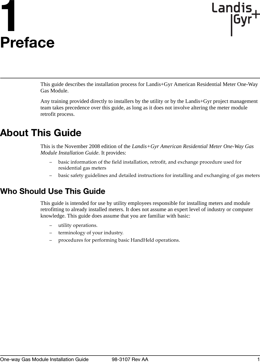
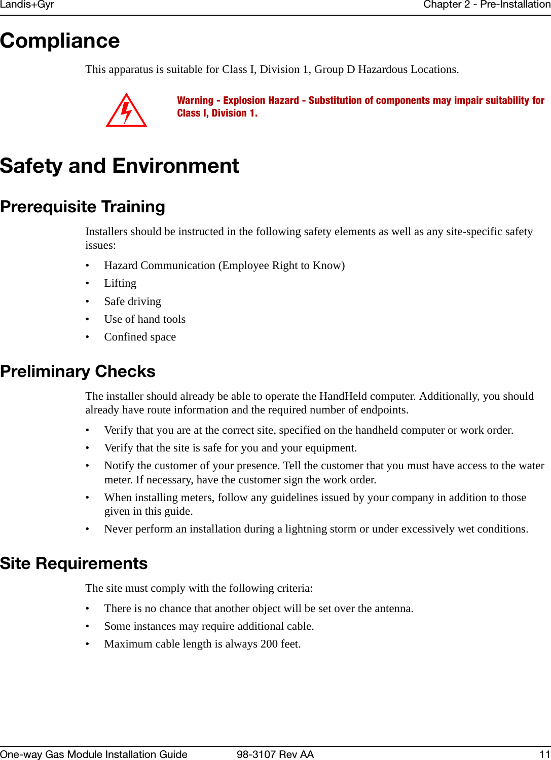
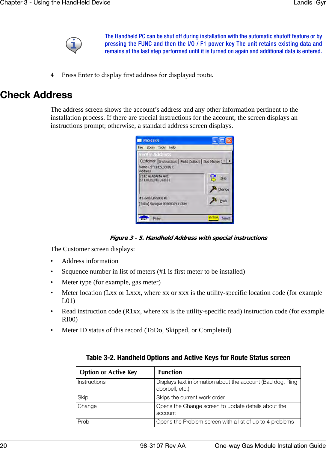
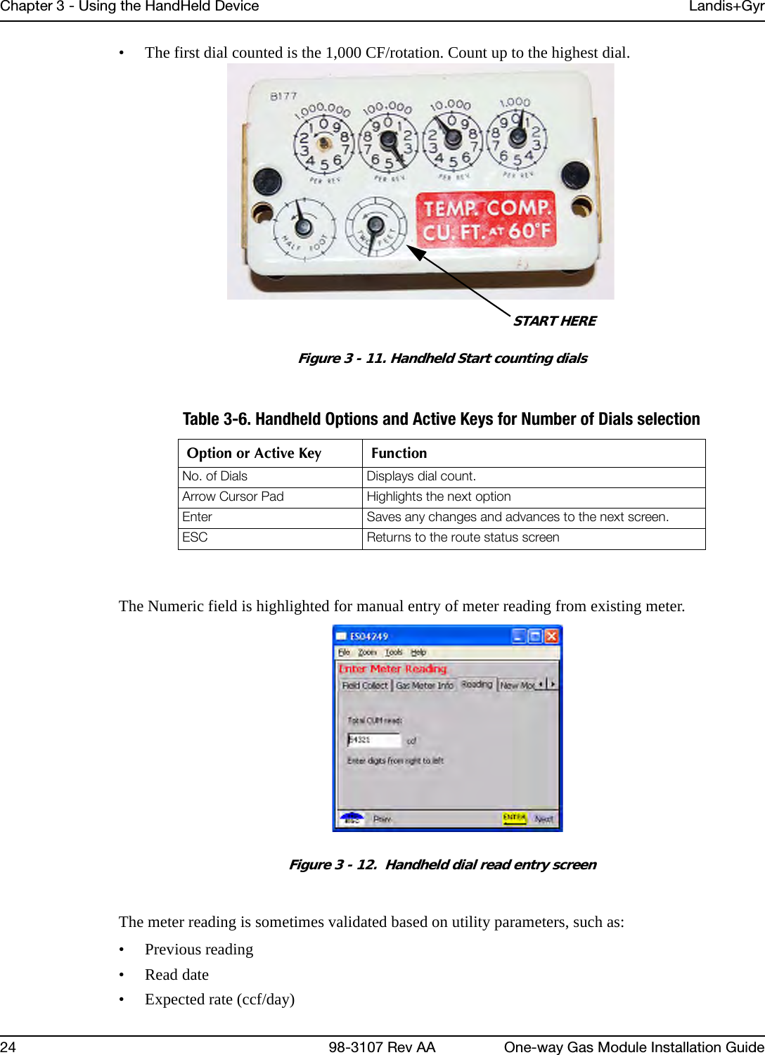
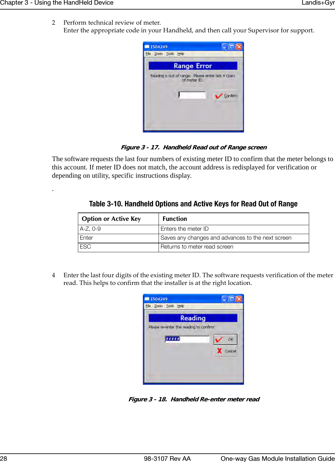
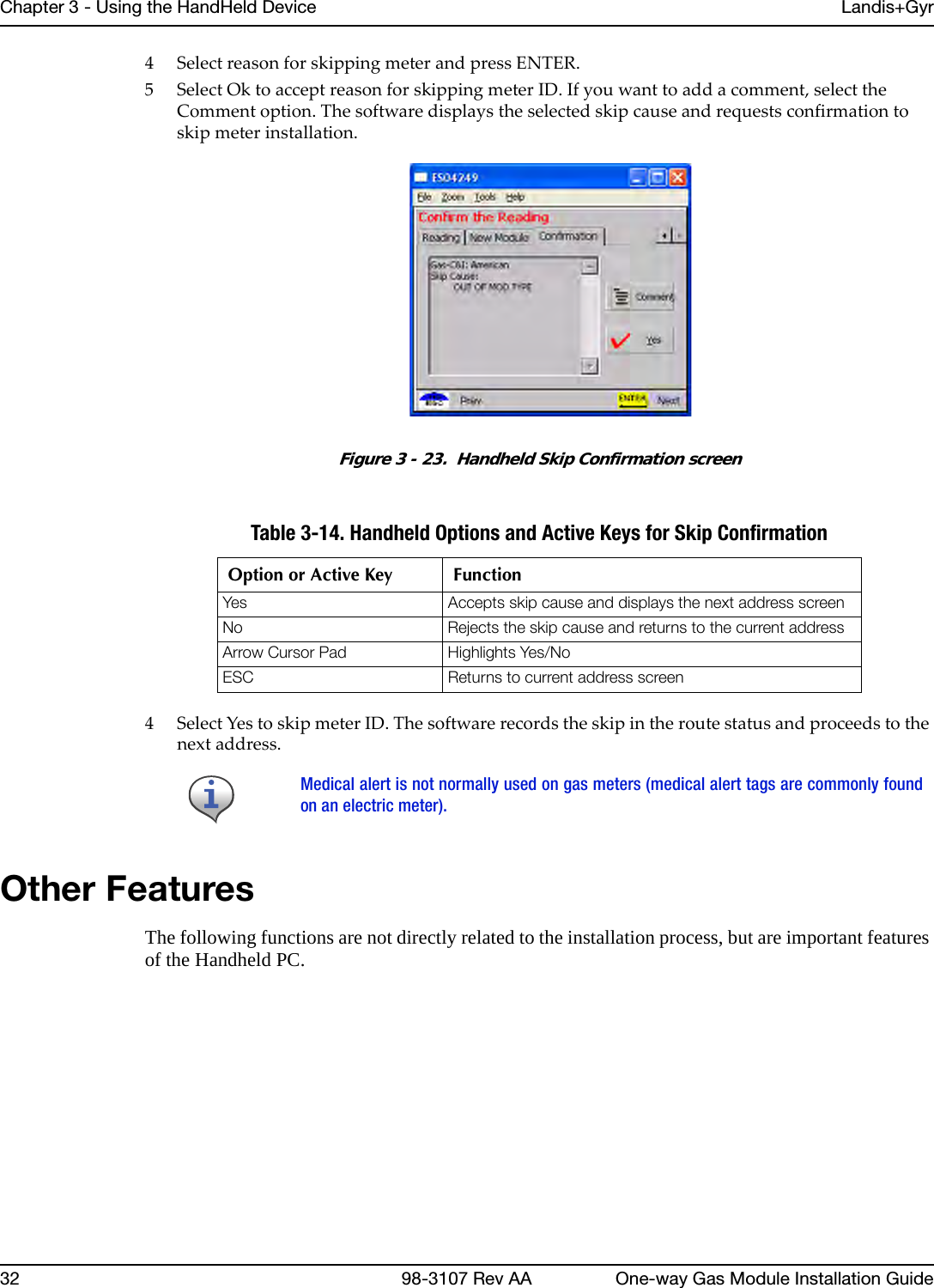
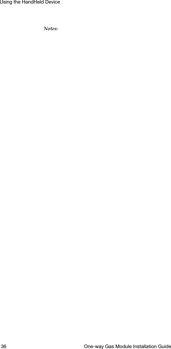
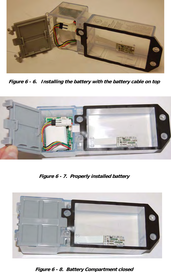
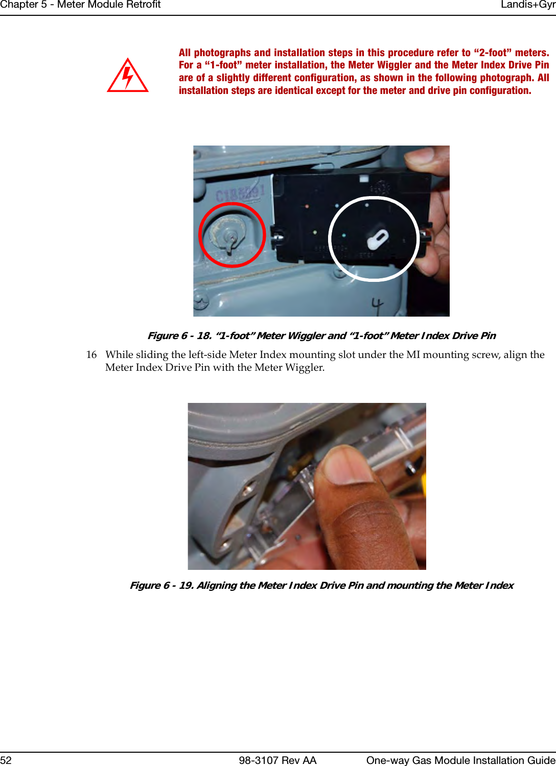
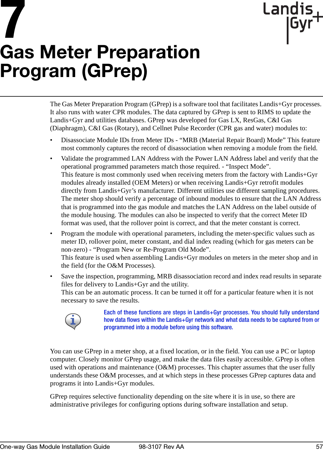
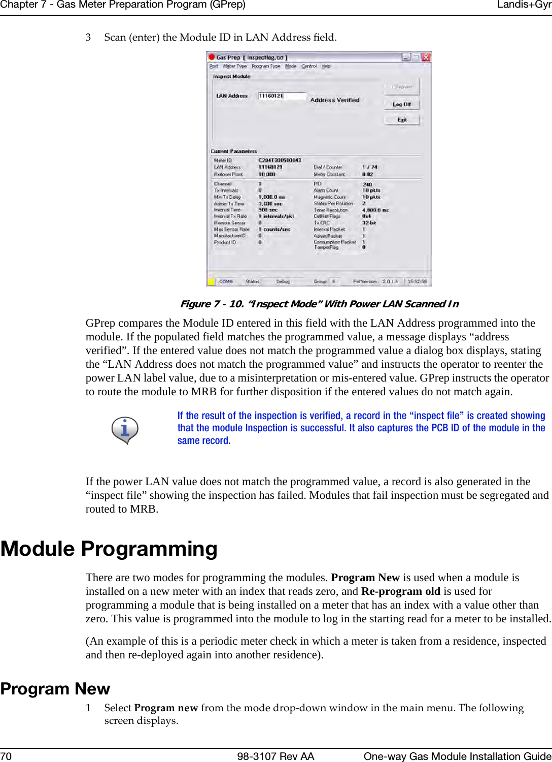
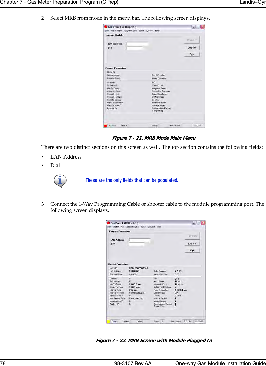
![Landis+Gyr Chapter 7 - Gas Meter Preparation Program (GPrep)One-way Gas Module Installation Guide 98-3107 Rev AA 61; ReadLog=readdlog - readdlog.txt in the GPrep program directory; ReadLog=- Do not write an inspection log file; ------------------------------------------------------------------------------; MaxAssociations is the maximum number of LANAddress / Meter ID associations; checked from the log file to assure that duplications are not assigned.; This requires 24 bytes of memory per association. Set to 0 to disable.;; Examples:;; MaxAssociations=1000 - Previous 1000 records are checked (memory = 24,000); MaxAssociations=10000 - Previous 10000 records are checked (memory = 240,000); MaxAssociations=0 - Disables duplication association checking.; ------------------------------------------------------------------------------Mode=ReProgramModuleClass=1RolloverPoint1=1000000MeterConstant1=0.050000SerialPort=1Operator=BillLocation=xdcsuUtility=SCGRolloverPoint0=10000MeterConstant0=0.020000RolloverPoint3=100000MeterConstant3=1.000000RolloverPoint2=100000MeterConstant2=0.100000MeterConstant4=0.250000ProgramMode=YesProgramDial=YesRolloverPoint=100000MeterConstant=1.000000LastFile=WCPR.SET[Control]meterID=?????????DeviceID=?????RGAS=yesCIGD=yesCIGR=yesCPRANT=yesCPRAWT=yesCPRCWT=yesWCPR=yesInspect=yesProgramNew=yesProgramOld=yesMRBMode=yesIndexRead=NProgramLog=c:\programlog.txtinspectLog=c:\inspectlog.txtMRBLog=c:\MRBlog.txtReadLog=c:\readlog.txtwProgramLog=c:\wprogramlog.txtwinspectLog=c:\winspectlog.txtwMRBLog=c:\wMRBlog.txt[RGAS]MeterConstantCount=4](https://usermanual.wiki/Landis-Gyr-Technology/GRAMCNLX1/User-Guide-1057800-Page-66.png)
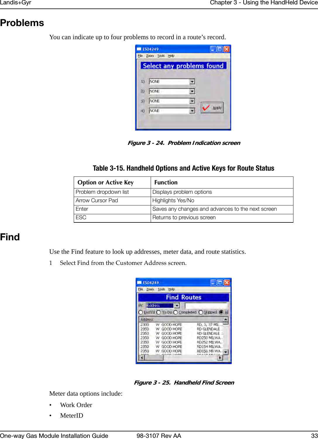
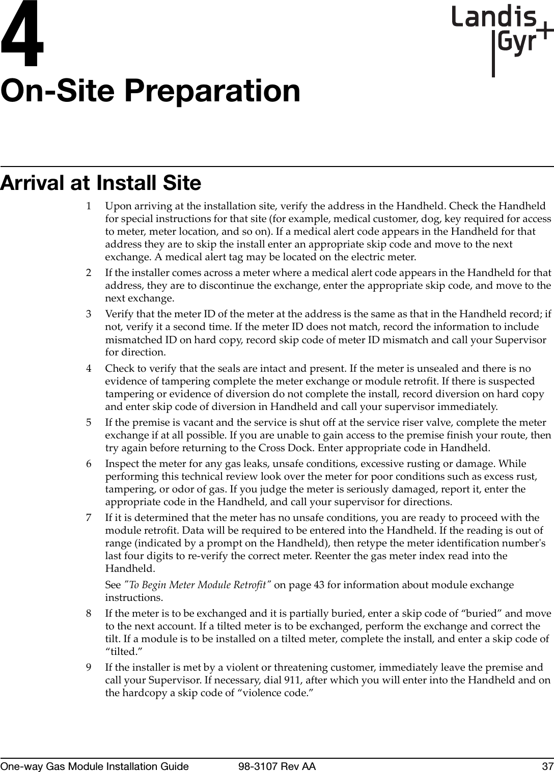
![Chapter 7 - Gas Meter Preparation Program (GPrep) Landis+Gyr62 98-3107 Rev AA One-way Gas Module Installation GuideMeterConstant1=.01MeterConstant2=.0112MeterConstant3=.02MeterConstant4=.0225RollOverPointCount=5RollOverPoint1=100RollOverPoint2=1,000RollOverPoint3=10,000RollOverPoint4=100,000RollOverPoint5=100000000[CPRAWT]MeterConstantCount=9MeterConstant1=.01MeterConstant2=.01121MeterConstant3=.02MeterConstant4=.0225MeterConstant5=.05MeterConstant6=.0562MeterConstant7=.1MeterConstant8=.112MeterConstant9=1.0RollOverPointCount=6RollOverPoint1=100RollOverPoint2=1,000RollOverPoint3=10,000RollOverPoint4=100,000RollOverPoint5=100,00000RollOverPoint6=100,000000[CPRANT]MeterConstantCount=10MeterConstant1=.01MeterConstant2=.01121MeterConstant3=.02MeterConstant4=.0225MeterConstant5=.05MeterConstant6=.0562MeterConstant7=.1MeterConstant8=.112MeterConstant9=1.0MeterConstant10=2.0RollOverPointCount=5RollOverPoint1=100RollOverPoint2=1,000RollOverPoint3=10,000RollOverPoint4=100,000RollOverPoint5=100,000,000[CPRCWT]MeterConstantCount=9MeterConstant1=.01MeterConstant2=.01121MeterConstant3=.02MeterConstant4=.0225MeterConstant5=.05MeterConstant6=.0562MeterConstant7=.1MeterConstant8=.112MeterConstant9=1.0RollOverPointCount=5](https://usermanual.wiki/Landis-Gyr-Technology/GRAMCNLX1/User-Guide-1057800-Page-67.png)
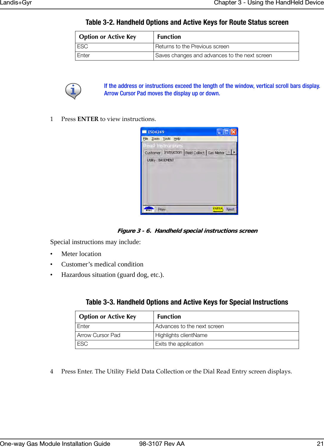
![Landis+Gyr Chapter 7 - Gas Meter Preparation Program (GPrep)One-way Gas Module Installation Guide 98-3107 Rev AA 63RollOverPoint1=100RollOverPoint2=1,000RollOverPoint3=10,000RollOverPoint4=100,000RollOverPoint5=99999999[CIGR]MeterConstantCount=5MeterConstant1=.05MeterConstant2=.0562MeterConstant3=.1MeterConstant4=.112MeterConstant5=1.0RollOverPointCount=5RollOverPoint1=100RollOverPoint2=1,000RollOverPoint3=10,000RollOverPoint4=100,000RollOverPoint5=100,0000[CIGD]MeterConstantCount=5MeterConstant1=.05MeterConstant2=.0562MeterConstant3=.1MeterConstant4=.112MeterConstant5=1.0RollOverPointCount=5RollOverPoint1=100RollOverPoint2=1,000RollOverPoint3=10,000RollOverPoint4=100,000RollOverPoint5=100,0000[WCPR]MeterConstantCount=1MeterConstant1=1RollOverPointCount=5RollOverPoint1=100RollOverPoint2=1,000RollOverPoint3=10,000RollOverPoint4=100,000RollOverPoint5=100,0000Save your updates to the GPrep.ini file. GPrep is ready to use.Data TransferA local RIMS analyst performs this process. The RIMS Analyst uploads MRB and Program files to the server via FTP.Server Side ProcessThe person using GPrep, or the local administrator, posts the program log and MRB files to Landis+Gyr's FTP Server. You can use any SFTP Tool to post files from gas and water processes. The GPREP.ini file determines the name and path of the files generated in the local machine. Each](https://usermanual.wiki/Landis-Gyr-Technology/GRAMCNLX1/User-Guide-1057800-Page-68.png)
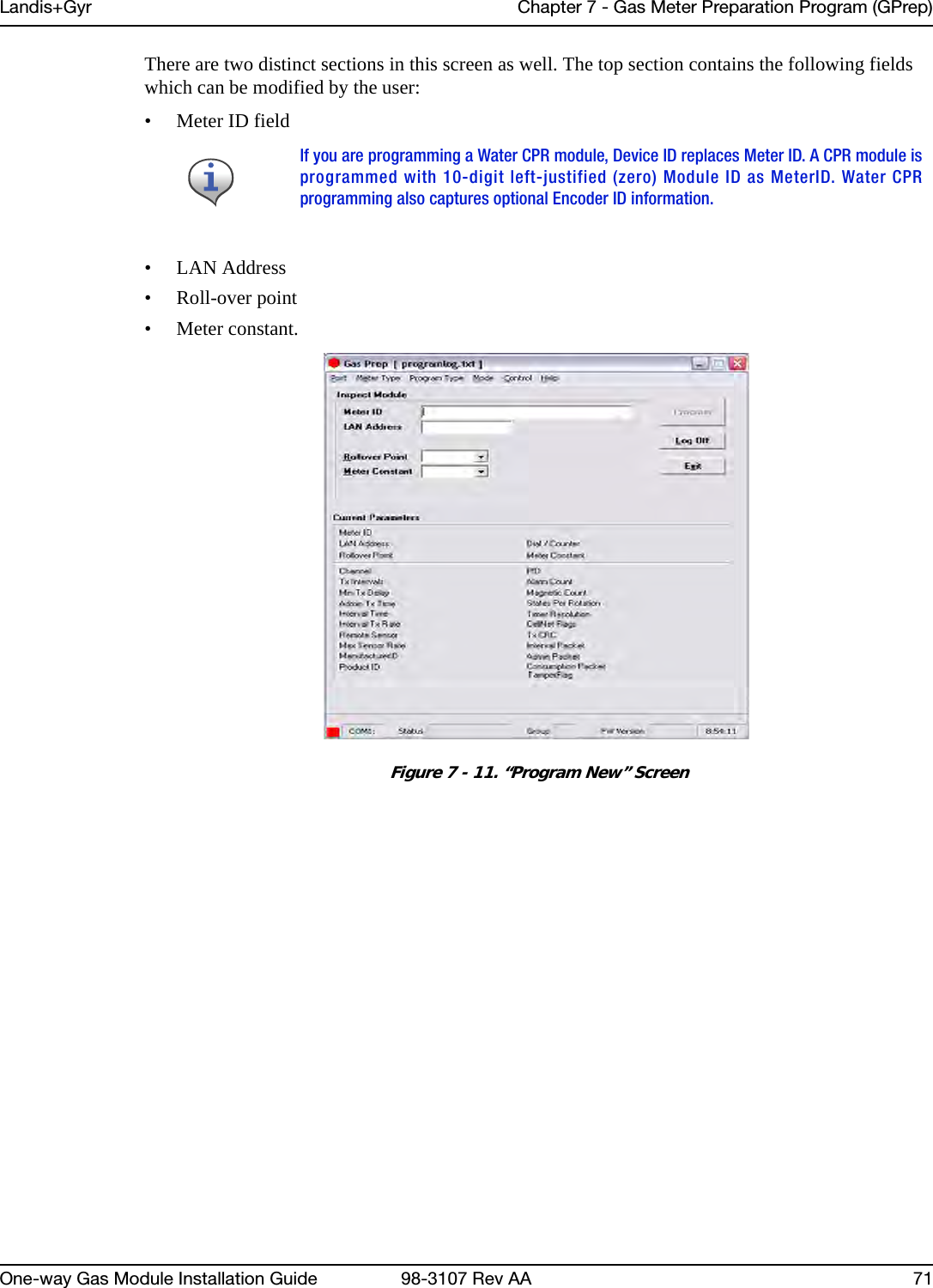
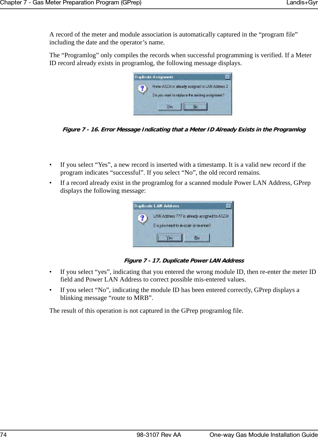
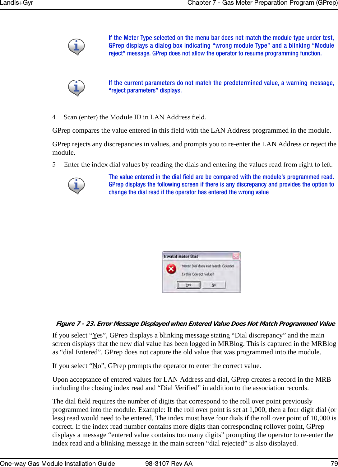
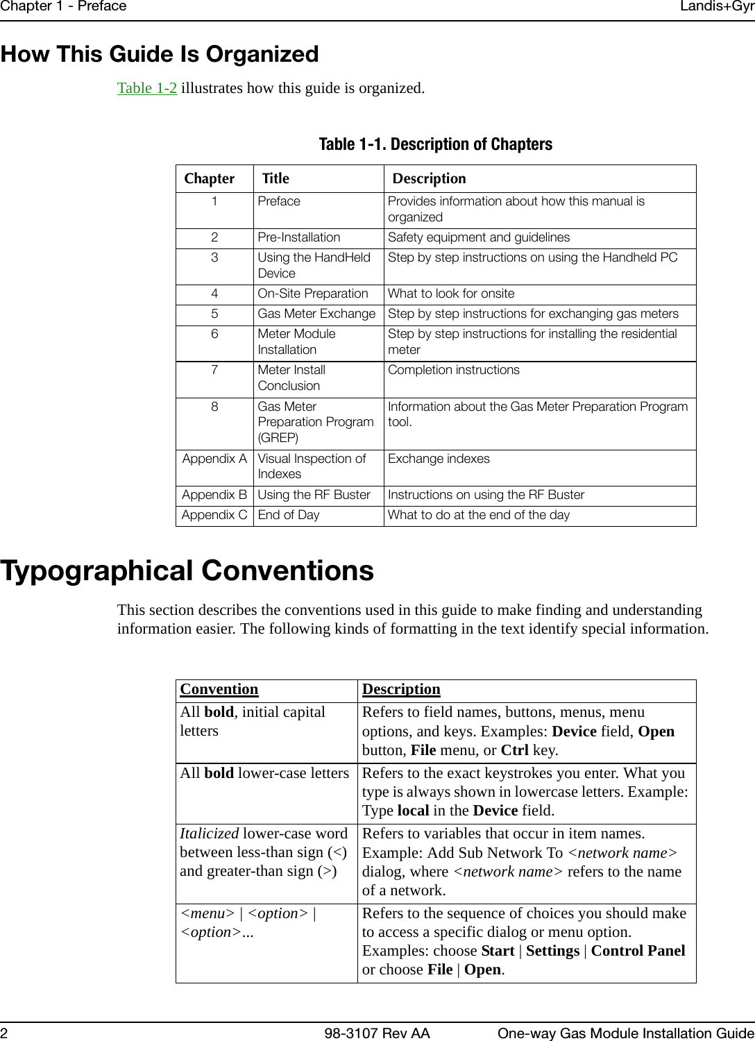
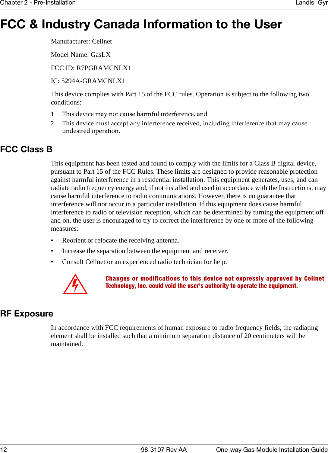
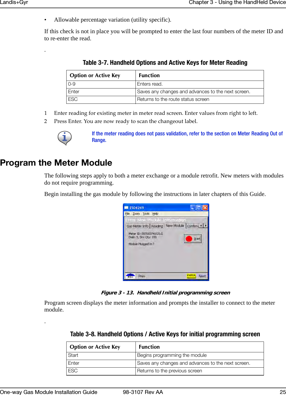
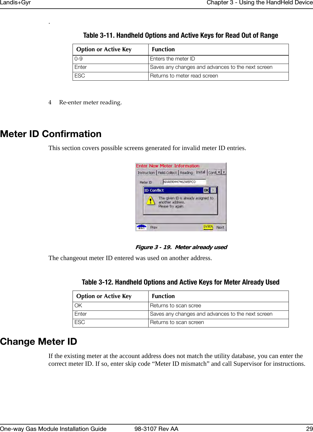
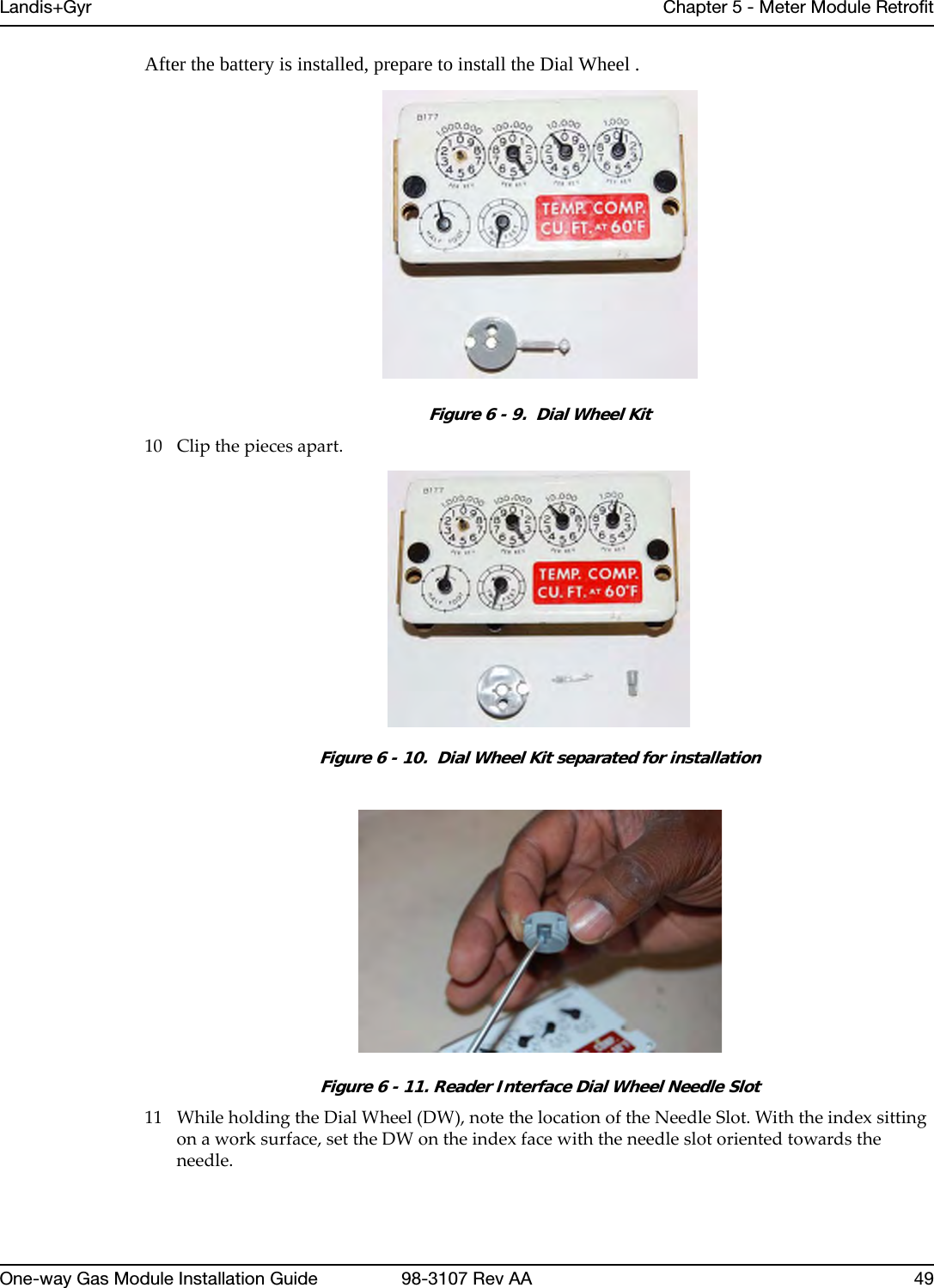
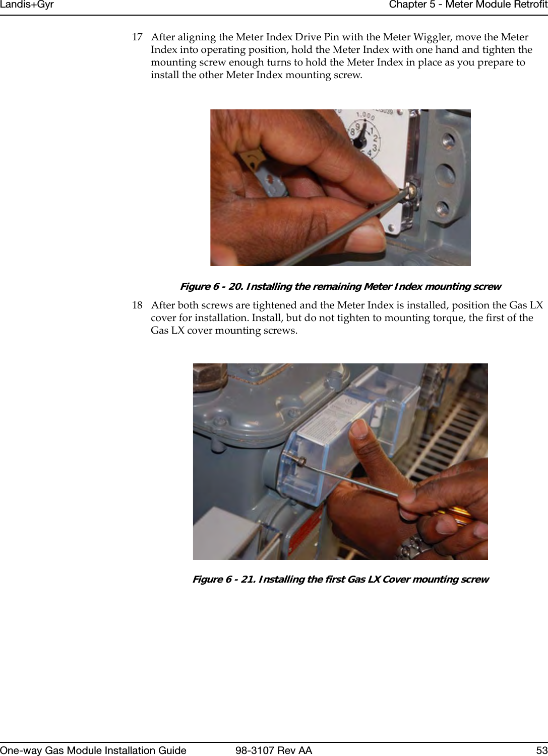
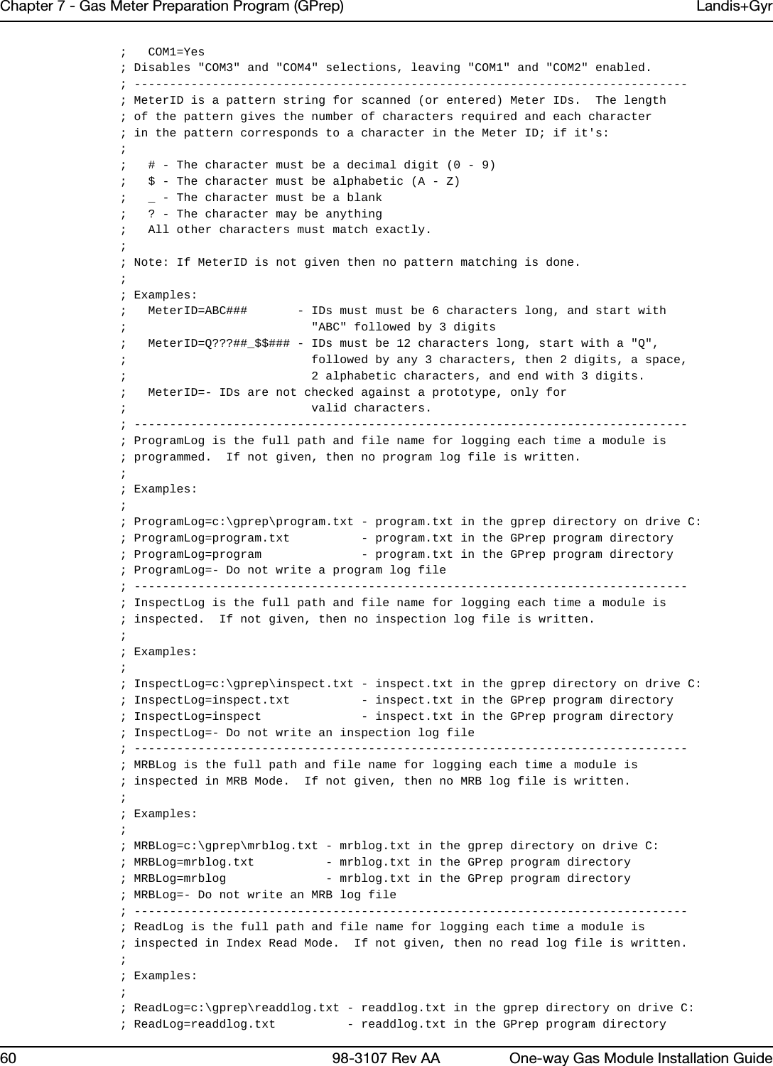
![Landis+Gyr Chapter 7 - Gas Meter Preparation Program (GPrep)One-way Gas Module Installation Guide 98-3107 Rev AA 8112 WhataresometroubleshootingstepsifGPrepisnotworking?–Ifyouareusingtheshooterbox,check:—ACpower—modulepluggedin— shooterboxturnedon— correctDB9toDB9(RS‐232)cable(Non‐NullModem)— correctCOMport— correctmetertypeandmode(e.g.GasLXv.commercial)–IfyouareusingUSBonewayprogrammingcable,refertothe1‐WayModuleProgrammingCablePC/LaptopGettingStartedGuide.13 Whatarethebenefitsofusingre‐programoldallofthetimeasopposedtoprogramnew?Whilesomeprogramsdothis,therearenorealbenefits.Itisalittleeasiertopreparetheprogramlogtosend,butinvolvesextraworkfortheenduser.14 Whatdoesitmeanwhenafileissuperseded?AmeterIDorLANAddresshadtobere‐entered.15 Whoisresponsibleforcleaningthesefiles(removingsupersedes,convertingintoanExcelspreadsheet,etc.)?Typically,theutilitydesignatedpersonneltoperformthistaskbeforesendingthesefilestothedatabaseanalyst.16 WhoshouldIcontactifthereisaproblem?Contactalocaldatabaseanalyst.Ifneeded,contactLandis+GyrCustomerSupportatëçäìíáçåëìééçêíKå~]ä~åÇáëÖóêKÅçã.17 Whenusingdifferentscreens,whydoesthephrase“parameterreject”flashyellowwhenIpluginamodulethathasjustcomefromthemanufacturer?Whenmodulesaremanufacturedandconfigured,testparametersareprogrammedtomakethemoduletransmitmorefrequentlythanevery15minutes.Theseparametersalsoallowotherteststoberunonthemodulesforqualitycontrolprocedures.GPrep(orahandheld)replacesthesetestparameterswithfieldparameters.](https://usermanual.wiki/Landis-Gyr-Technology/GRAMCNLX1/User-Guide-1057800-Page-86.png)


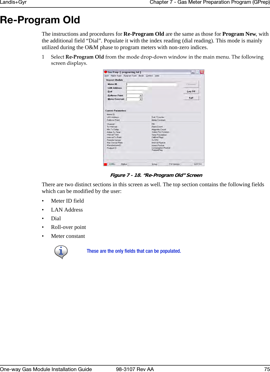
![Landis+Gyr Appendix C - End of Day Handheld InstructionsOne-way Gas Module Installation Guide 98-3107 Rev AA 91How To Change The Handheld ID Occasionally the Handheld ID may be entered incorrectly or the wrong Handheld ID may be in a Handheld because of a memory card exchange. This section tells how to change the Handheld ID to the correct number. 1PlacetheHandheldinthecradleanddockit.2OpenupthemostrecentversionofHandheldEdit.3Select“Communication”then“TransferFiles”fromthemenuonHandheldEdit.4Ontherightsideofthepopupwindow,doubleclickonthe[CELLNET]folder.5SelectUnitinfo.datanddeleteit.Select“Yes”toverifythatyouwanttodeletethefile.6Select“OK”onthepopupwindowandcloseHandheldEdit.7TheHandheldwillthenpromptyoutoenterthelast4digitsoftheserialnumberonthebackoftheHandheld.8BeforeusingtheHandheld,makesuretheproperrouteinformationisloadedintotheHandheld.Known Common Problems• If the Handheld gets jarred, the memory card may become dislodged slightly. This makes it look like all of the data has been lost- but it is still there. Unscrew the two screws at the top of the Handheld below the Infra-red scanner. Re-seat the card and re-tighten the cover. You may need to re-boot the Handheld. • If the blue key and then one of the arrow keys is pushed, part of the screen seems to disappear. The screen was designed to hold more data. Blue key + arrow is how you shift the screen to view that data. Push the blue button and the arrow key in the opposite direction of the screen shift.](https://usermanual.wiki/Landis-Gyr-Technology/GRAMCNLX1/User-Guide-1057800-Page-96.png)
![Reader’s Comment FormAmericanResidentialMeterOne‐WayGasModuleInstallationGuide(98‐3107RevAA)Pleaseusethisformonlytoidentifypublicationerrorsortorequestchangesinpublications.Yourcommentsassistusinimprovingourpublications.Directanyrequestsforadditionalpublications,technicalquestionsaboutsystems,changesinsupport,andsoon,toyourLandis+Gyrsalesrepresentative.Youmustusethisformtocommunicateyourcommentsaboutthispublication,itsorganization,orsubjectmatter,withtheunderstandingthatwemayuseordistributewhateverinformationyousupplyinanywaywebelieveappropriatewithoutincurringanyobligationtoyou.Youcansendcommentsviaemail,conventionalmail,orfax.Ifyourcommentdoesnotneedareply(forexample,pointingoutatypingerror),checkthisboxanddonotincludeyournameandaddressbelow.Ifyourcommentisapplicable,wewillincludeitinthenextrevisionofthemanual.Ifyouwouldlikeareply,checkthisbox.Pleaseprintyournameandaddressbelow.(Pleaseprint.)To send your comments via... Use this contact information...bã~áä =ëçäìíáçåëìééçêíKå~]ä~åÇáëÖóêKÅçã`çåîÉåíáçå~ä=ã~áä i~åÇáëHdóêI=PMMMM=jáää=`êÉÉâ=^îÉKI=pìáíÉ=NMMI=^äéÜ~êÉíí~I=d^=PMMOOc~ñ ESTUF=ORUJNRRMPage CommentsDate CompanyNameYourName MailingAddressPhoneNo.Email](https://usermanual.wiki/Landis-Gyr-Technology/GRAMCNLX1/User-Guide-1057800-Page-100.png)