Landis Gyr Technology GRAMCNLX1 GasLX Residential American User Manual Installation Guide
Landis+Gyr Technology, Inc. GasLX Residential American Installation Guide
Installation Guide

5015 B.U. Bowman Drive Buford, GA 30518 USA Voice: 770-831-8048 Fax: 770-831-8598
Certification Exhibit
FCC ID: R7PGRAMCNLX1
IC: 5294A-GRAMCNLX1
FCC Rule Part: 15.247
IC Radio Standards Specification: RSS-210
ACS Report Number: 08-0433 - 15C
Manufacturer: Cellnet Technology, Inc.
Model: GasLX Residential American
Installation Guide

American Residential Meter
One-Way Gas Module
Installation Guide
98-3107 Rev AA
Limitation on Warranties and Liability
Information in this document is subject to change without notice. This manual or any part of it thereof may not be
reproduced in any form unless permitted by contract or by written permission of Landis+Gyr.
In no event will Landis+Gyr be liable for any incidental, indirect, special, or consequential damages (including lost
profits) arising out of or relating to this publication or the information contained in it, even if Landis+Gyr has been
advised, knew, or should have known of the possibility of such damages.
© 2008 Landis+Gyr. All Rights Reserved.
Trademarks
Cellnet® is a registered trademark of Cellnet Innovations, Inc.
Other brands or product names are the trademarks or registered trademarks of their respective holders.s.

One-way Gas Module Installation Guide 98-3107 Rev AA i
Table of Contents
Chapter 1: Preface
Chapter 2: Pre-Installation . . . . . . . . . . . . . . . . . . . . . . . . . . . . . . . . . . . . . . . . . . . . . . . . . . . . . . . . . . . 7
Chapter 3: Using the HandHeld Device . . . . . . . . . . . . . . . . . . . . . . . . . . . . . . . . . . . . . . . . . . . . . . . . . 15
Chapter 4: On-Site Preparation . . . . . . . . . . . . . . . . . . . . . . . . . . . . . . . . . . . . . . . . . . . . . . . . . . . . . . . 37
Chapter 5: Gas Meter Exchange . . . . . . . . . . . . . . . . . . . . . . . . . . . . . . . . . . . . . . . . . . . . . . . . . . . . . . 39
Chapter 6: Meter Module Retrofit . . . . . . . . . . . . . . . . . . . . . . . . . . . . . . . . . . . . . . . . . . . . . . . . . . . . . 45
Chapter 7: Gas Meter Preparation Program (GPrep) . . . . . . . . . . . . . . . . . . . . . . . . . . . . . . . . . . . . . . 57
Appendix A: Supplemental Information About Indexes . . . . . . . . . . . . . . . . . . . . . . . . . . . . . . . . . . . . 83
Appendix B: Using the RF Buster . . . . . . . . . . . . . . . . . . . . . . . . . . . . . . . . . . . . . . . . . . . . . . . . . . . . . 85
Appendix C: End of Day Handheld Instructions . . . . . . . . . . . . . . . . . . . . . . . . . . . . . . . . . . . . . . . . . . 89

Table of Contents Landis+Gyr
ii 98-3107 Rev AA One-way Gas Module Installation Guide

1
One-way Gas Module Installation Guide 98-3107 Rev AA 1
Preface
This guide describes the installation process for Landis+Gyr American Residential Meter One-Way
Gas Module.
Any training provided directly to installers by the utility or by the Landis+Gyr project management
team takes precedence over this guide, as long as it does not involve altering the meter module
retrofit process.
About This Guide
This is the November 2008 edition of the Landis+Gyr American Residential Meter One-Way Gas
Module Installation Guide. It provides:
–basicinformationofthefieldinstallation,retrofit,andexchangeprocedureusedfor
residentialgasmeters
–basicsafetyguidelinesanddetailedinstructionsforinstallingandexchangingofgasmeters
Who Should Use This Guide
This guide is intended for use by utility employees responsible for installing meters and module
retrofitting to already installed meters. It does not assume an expert level of industry or computer
knowledge. This guide does assume that you are familiar with basic:
– utilityoperations.
– terminologyofyourindustry.
– proceduresforperformingbasicHandHeldoperations.
Chapter 1 - Preface Landis+Gyr
2 98-3107 Rev AA One-way Gas Module Installation Guide
How This Guide Is Organized
Table 1-2 illustrates how this guide is organized.
Typographical Conventions
This section describes the conventions used in this guide to make finding and understanding
information easier. The following kinds of formatting in the text identify special information.
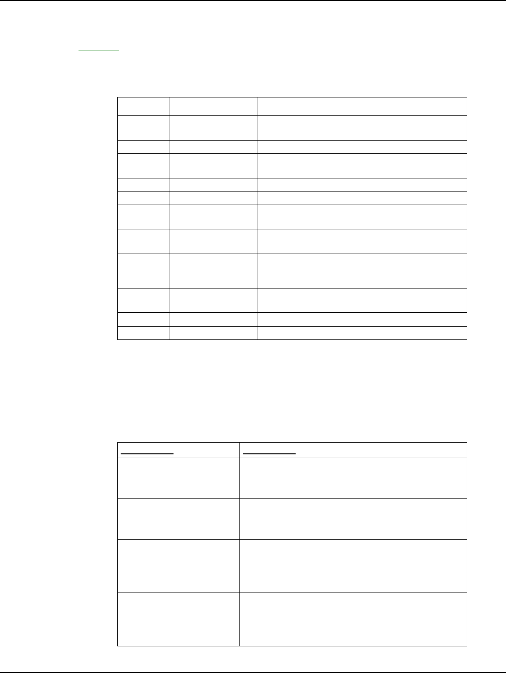
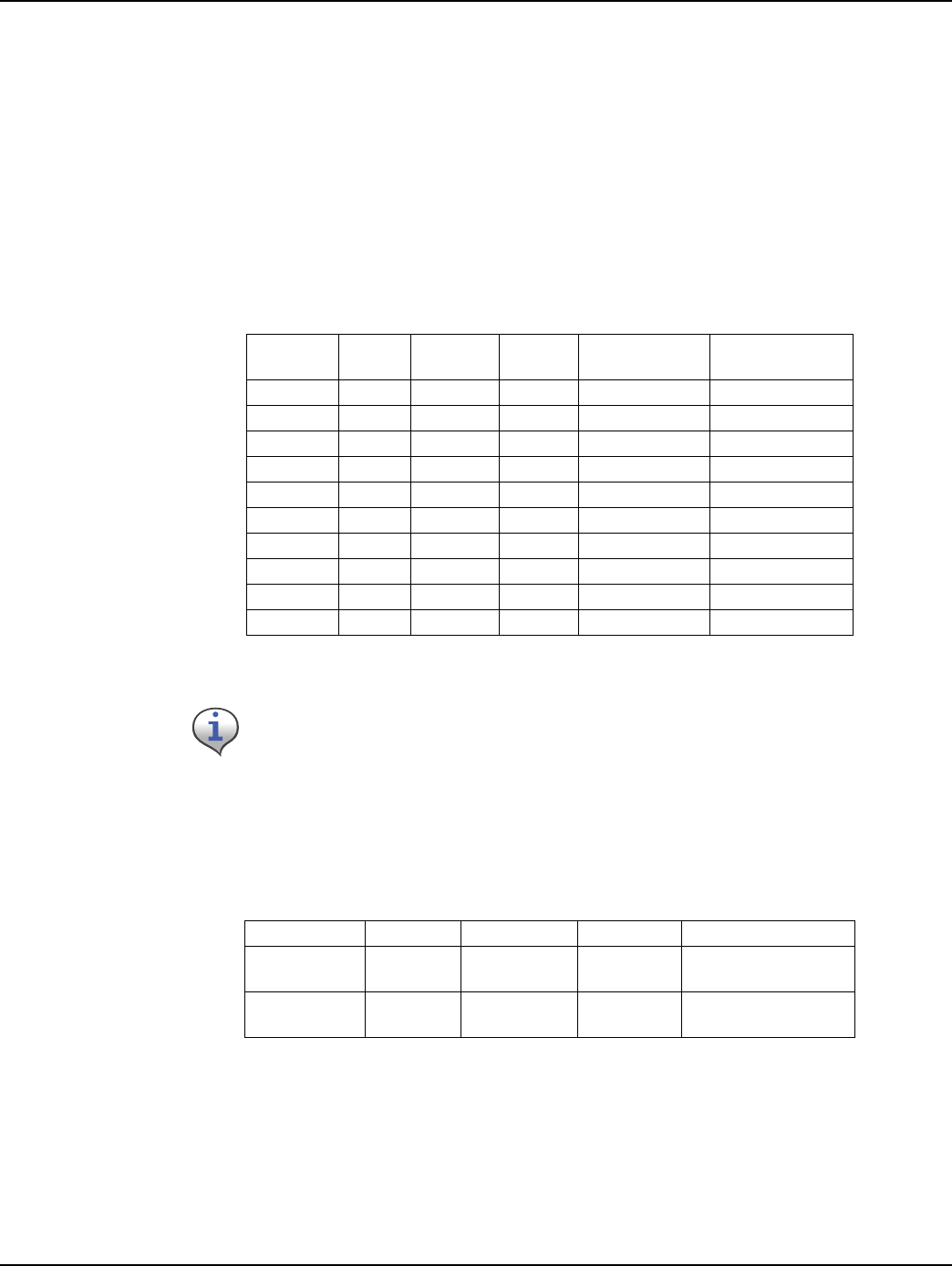
Table 1-1. Description of Chapters
Chapter Title Description
N mêÉÑ~ÅÉ mêçîáÇÉë=áåÑçêã~íáçå=~Äçìí=Üçï=íÜáë=ã~åì~ä=áë=
çêÖ~åáòÉÇ
O mêÉJfåëí~ää~íáçå p~ÑÉíó=ÉèìáéãÉåí=~åÇ=ÖìáÇÉäáåÉë
P rëáåÖ=íÜÉ=e~åÇeÉäÇ=
aÉîáÅÉ
píÉé=Äó=ëíÉé=áåëíêìÅíáçåë=çå=ìëáåÖ=íÜÉ=e~åÇÜÉäÇ=m`
Q låJpáíÉ=mêÉé~ê~íáçå tÜ~í=íç=äççâ=Ñçê=çåëáíÉ
R d~ë=jÉíÉê=bñÅÜ~åÖÉ píÉé=Äó=ëíÉé=áåëíêìÅíáçåë=Ñçê=ÉñÅÜ~åÖáåÖ=Ö~ë=ãÉíÉêë
S jÉíÉê=jçÇìäÉ=
fåëí~ää~íáçå
píÉé=Äó=ëíÉé=áåëíêìÅíáçåë=Ñçê=áåëí~ääáåÖ=íÜÉ=êÉëáÇÉåíá~ä=
ãÉíÉê
T jÉíÉê=fåëí~ää=
`çåÅäìëáçå
`çãéäÉíáçå=áåëíêìÅíáçåë
U d~ë=jÉíÉê=
mêÉé~ê~íáçå=mêçÖê~ã=
EdobmF
fåÑçêã~íáçå=~Äçìí=íÜÉ=d~ë=jÉíÉê=mêÉé~ê~íáçå=mêçÖê~ã=
íççäK
^ééÉåÇáñ=^ sáëì~ä=fåëéÉÅíáçå=çÑ=
fåÇÉñÉë
bñÅÜ~åÖÉ=áåÇÉñÉë
^ééÉåÇáñ=_ rëáåÖ=íÜÉ=oc=_ìëíÉê fåëíêìÅíáçåë=çå=ìëáåÖ=íÜÉ=oc=_ìëíÉê
^ééÉåÇáñ=` båÇ=çÑ=a~ó tÜ~í=íç=Çç=~í=íÜÉ=ÉåÇ=çÑ=íÜÉ=Ç~ó
Convention Description
All bold, initial capital
letters Refers to field names, buttons, menus, menu
options, and keys. Examples: Device field, Open
button, File menu, or Ctrl key.
All bold lower-case letters Refers to the exact keystrokes you enter. What you
type is always shown in lowercase letters. Example:
Type local in the Device field.
Italicized lower-case word
between less-than sign (<)
and greater-than sign (>)
Refers to variables that occur in item names.
Example: Add Sub Network To <network name>
dialog, where <network name> refers to the name
of a network.
<menu> | <option> |
<option>... Refers to the sequence of choices you should make
to access a specific dialog or menu option.
Examples: choose Start | Settings | Control Panel
or choose File | Open.
Landis+Gyr Chapter 1 - Preface
One-way Gas Module Installation Guide 98-3107 Rev AA 3
Contacting Technical Support
Landis+Gyrtechnicalsupportisavailablebytelephoneoremail.Whenyoucontacttechnical
support,bepreparedtogiveexactdescriptionsof:
• The problem you encountered
• What happened and what you were doing when the problem occurred
• How you tried to solve the problem
• The exact text of any error messages
Telephone Access
Technical support is available Monday through Friday from 8:00 a.m. to 5:00 p.m. (ET) by calling
800-791-2567. If all support technicians are helping other customers, your call will be routed to the
Landis+Gyr Support voice mail system.
Leave a brief message that includes the following information:
•Your name
• Your company’s name
• Your telephone number
A support technician will return your call as soon as possible within normal business hours.
Technicians return all calls in the order that they are received.
Plus sign (+) between keys Refers to pressing the keys at the same time.
Example: Alt+B.
Comma (,) between keys Refers to keys which are pressed sequentially.
Example: Alt,F.
Note boxes provide essential information about Landis+Gyr Gas Meter Module and Meter
Installation.
Cautions provide information that you must read to avoid making relatively moderate errors
during Landis+Gyr Gas Meter Module and Meter Installation.
Warnings provide special, must-read information. If you ignore a warning, you may
create a safety hazard, omit essential data or make a critical error. Warnings are in
the same format as notes, except they are shown in bold text.
Convention Description

Chapter 1 - Preface Landis+Gyr
4 98-3107 Rev AA One-way Gas Module Installation Guide
Email Access
If you prefer, you may email a description of your problem to:
solutionsupport.na@landisgyr.com
A support technician will return your email as soon as possible within normal business hours.
Technicians return all emails in the order that they are received.
General Inquiries
Your feedback is important in helping to provide the most accurate and high-quality information. If
you want to reach a Landis+Gyr sales representative, or for other inquiries, do one of the following:
• Telephone: 678-258-1500
• Fax: 678-258-1550
You can also mail your comments or inquiries to:
Landis+Gyr
Attn:CustomerSupport
30000MillCreekAvenue
Suite100
Alpharetta, GA 30022
Ordering Publications
You can order publications from your sales representative. To order additional copies of this manual,
use order number:
98‐3107RevAA
Publication Comments
Landis+Gyr welcomes your feedback and comments. If you have comments or suggestions for
improving this publication, a form is provided at the back of this manual for reader’s comments. If
you would like a reply, please include your contact information:
•Name
• Telephone number or fax number
• Email address
• Company name and address
Be sure to include the following information along with your comment:
• Title and number of this manual
• Page number or topic related to your comment

Landis+Gyr Chapter 1 - Preface
One-way Gas Module Installation Guide 98-3107 Rev AA 5
Related Publications
The following document provides important related information.
Table 1-2. Related Publication
Document Description
NJt~ó=jçÇìäÉ=
mêçÖê~ããáåÖ=`~ÄäÉ
mêçÖê~ããáåÖ=íÜÉ=ãçÇìäÉ=îá~=~=m`=çê=ä~éíçé=~åÇ=íÜÉ=NJ
ï~ó=Å~ÄäÉ
Notes:
6 One-way Gas Module Installation Guide
Preface

2
One-way Gas Module Installation Guide 98-3107 Rev AA 7
Pre-Installation
Proper planning and thorough preparation are critical for successful installation. This chapter
outlines basic requirements for the pre-installation phase.
SAFETY OVERVIEW
Prior to starting the installation process, you must develop and launch an installer safety training
plan for initial, refresher, and ongoing safety training. Ensure that installers receive appropriate
initial and refresher training to meet their specific safety-related responsibilities. You must provide
safety training when:
• An existing installer assumes new duties for which he or she has not previously received
training.
• New processes and methodologies representing new risks are introduced into the installation
environment.
• Previously unidentified risks are reported.
The installation supervisory team assumes responsibility for ensuring that installers are properly
trained, authorized, and continually qualified to perform their work. The team must also take
responsibility for the safety of their installers and to assure safe work methodologies. Installers must
understand that their supervisor’s responsibility does not relieve them from their individual
responsibility to perform the work safely and to follow all safety rules and procedures applicable to
their work.
Table 2-1. Gas Meter Installation and Module Retrofit Tool List
qçêèìÉ=ëÅêÉïÇêáîÉê=ïáíÜ=î~êáçìë=ëäçí=~åÇ=
mÜáääáéë=íáéë
R=J=áå=J=N=ëÅêÉïÇêáîÉê
NQ?=máéÉ=ïêÉåÅÜ=EOF NU?=máéÉ=ïêÉåÅÜ=EOF
OQ?=máéÉ=ïêÉåÅÜ=ENF NQ?=ÅìêîÉÇ=à~ï=ÅÜ~ååÉä=äçÅâë=
@N=~åÇ=@O=mÜáääáéë=ëÅêÉï=ÇêáîÉê pÅêÉï=ÇêáîÉê=J=NLUJáåÅÜ=ëäçí=Ää~ÇÉ
_~ää=mÉÉå=e~ããÉê pÜçîÉä=~åÇ=ëé~ÇÉ
`êÉëÅÉåí=ïêÉåÅÜ taJQM
qÜêÉ~Ç=iìÄêáÅ~åí fÇÉåíáÑáÅ~íáçå
aççê=e~åÖÉêë `äáé=_ç~êÇë
mÉåëLmÉåÅáäë p~ÑÉíó=ÅçåÉë
pÅêÉïÇêáîÉêJ=½Ò=ëäçí=Ää~ÇÉ=ñ=NM? ^ïäI=eÉ~îó=Çìíó
eÉ~ÇäáÖÜí=Ñä~ëÜäáÖÜí _ê~ëë=ëÅê~éÉê=N=¼JáåÅÜ=ïáÇÉ
aá~Öçå~ä=ÅìííÉêë e~åÇÜÉäÇ
mÉêëçå~ä=mêçíÉÅíáîÉ=bèìáéãÉåí `äáéÄç~êÇ
Chapter 2 - Pre-Installation Landis+Gyr
8 98-3107 Rev AA One-way Gas Module Installation Guide
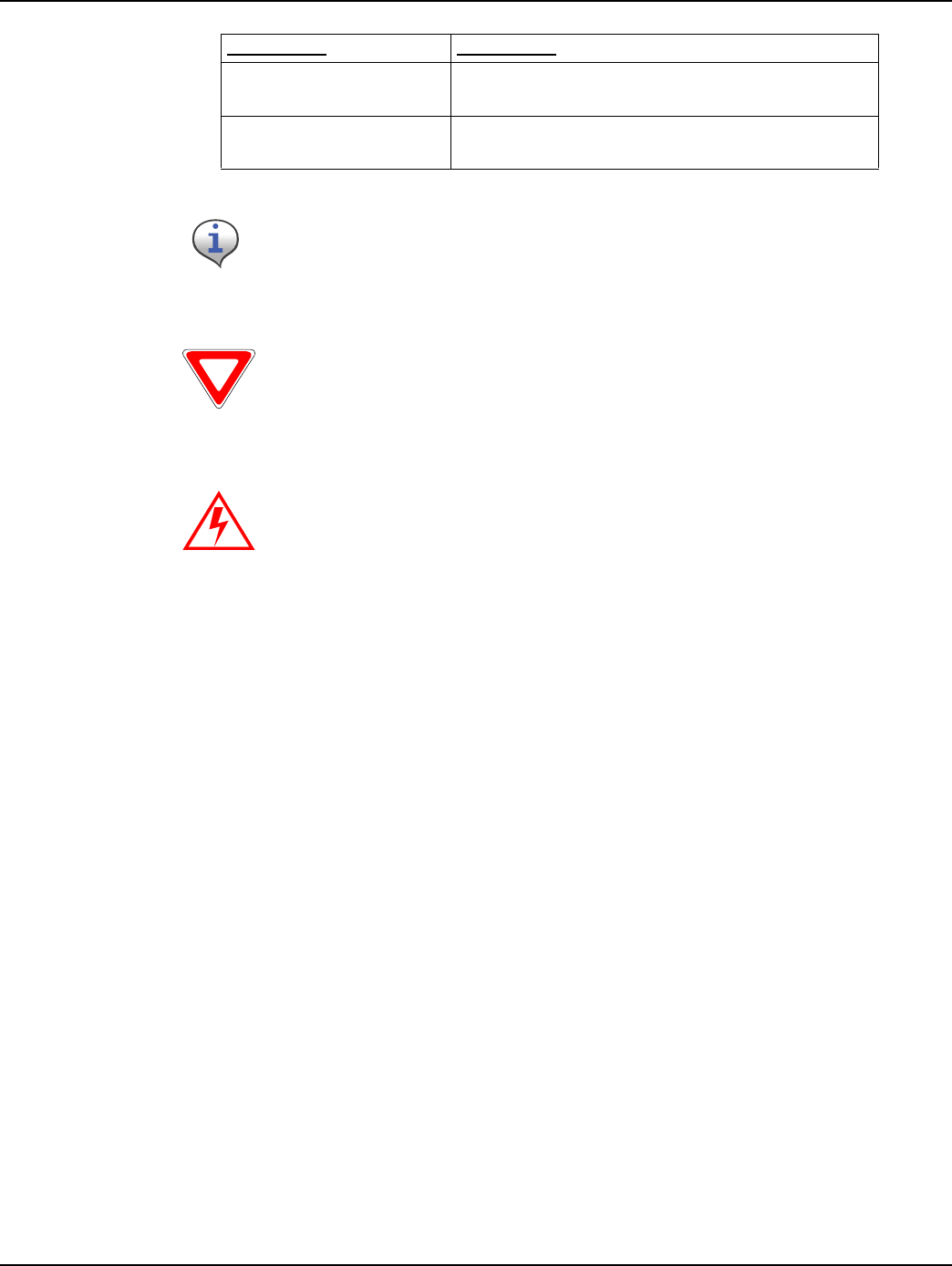
RF Busters
Verify that the RF Buster is working correctly. Press and hold the push button Switch. The LED
lights red, and the internal speaker sounds for approximately 1/2 second. If nothing happens or the
LED lights and speaker sound continuously, then the 9V battery is probably low and needs to be
replaced.
To access the battery compartment, open the spring-loaded cover on the back of the RF Buster. Take
care not to misplace the cover or damage the battery door spring mechanism.
Figure 2 - 1. RF Buster
See Appendix B, Using the RF Buster for detailed instructions on how to use the RF Buster.
píêÉÉí=^íä~ë oc=_ìëíÉêI=mLk=OSJNMRM
kçåJëé~êâ=Ñä~ëÜäáÖÜí `Éää=éÜçåÉ=çê=OJï~ó=ÅçããìåáÅ~íáçå=
ÇÉîáÅÉ
táêÉ=_êìëÜ `~ÄäÉ=íáÉë
“pÜççíÉêÒ=Å~ÄäÉ gìãéÉê=Å~ÄäÉë
iÉ~â=ÇÉíÉÅíáçå=ëç~é mêÉëëìêÉ=Ö~ìÖÉë
dêÉó=ëéê~ó=é~áåí=~åÇ=é~áåí=Äç~êÇ=Eíç=
éêÉîÉåí=çîÉê=ëéê~óáåÖF
aÉ~Ç=Ääçï=Ü~ããÉê
^åó=êÉèìáêÉÇ=ëéÉÅá~äíó=íççäë
Your supervisor carries shovels, spades, hack saws, other specialty tools, and ladders.
Take care to check the work area each time you change locations. Be certain there are no
tools left behind.
Table 2-1. Gas Meter Installation and Module Retrofit Tool List
Landis+Gyr Chapter 2 - Pre-Installation
One-way Gas Module Installation Guide 98-3107 Rev AA 9
Handhelds (Handheld)
Handhelds are rugged, but you should still always handle them carefully. If the unit fails to operate
in the field, page your Supervisor for help. If possible, the Supervisor will assist in correcting the
problem or bring a replacement unit out to you.
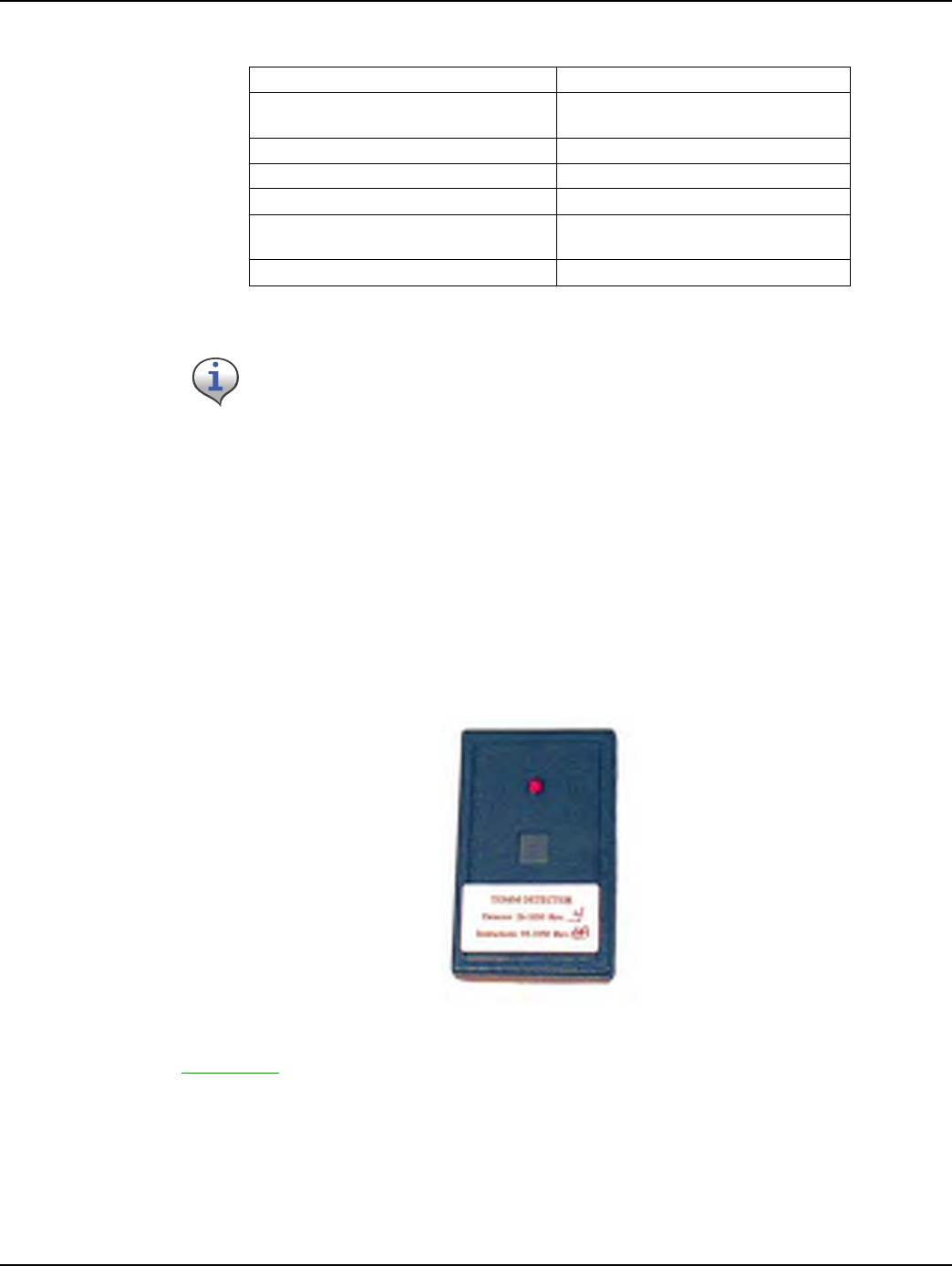
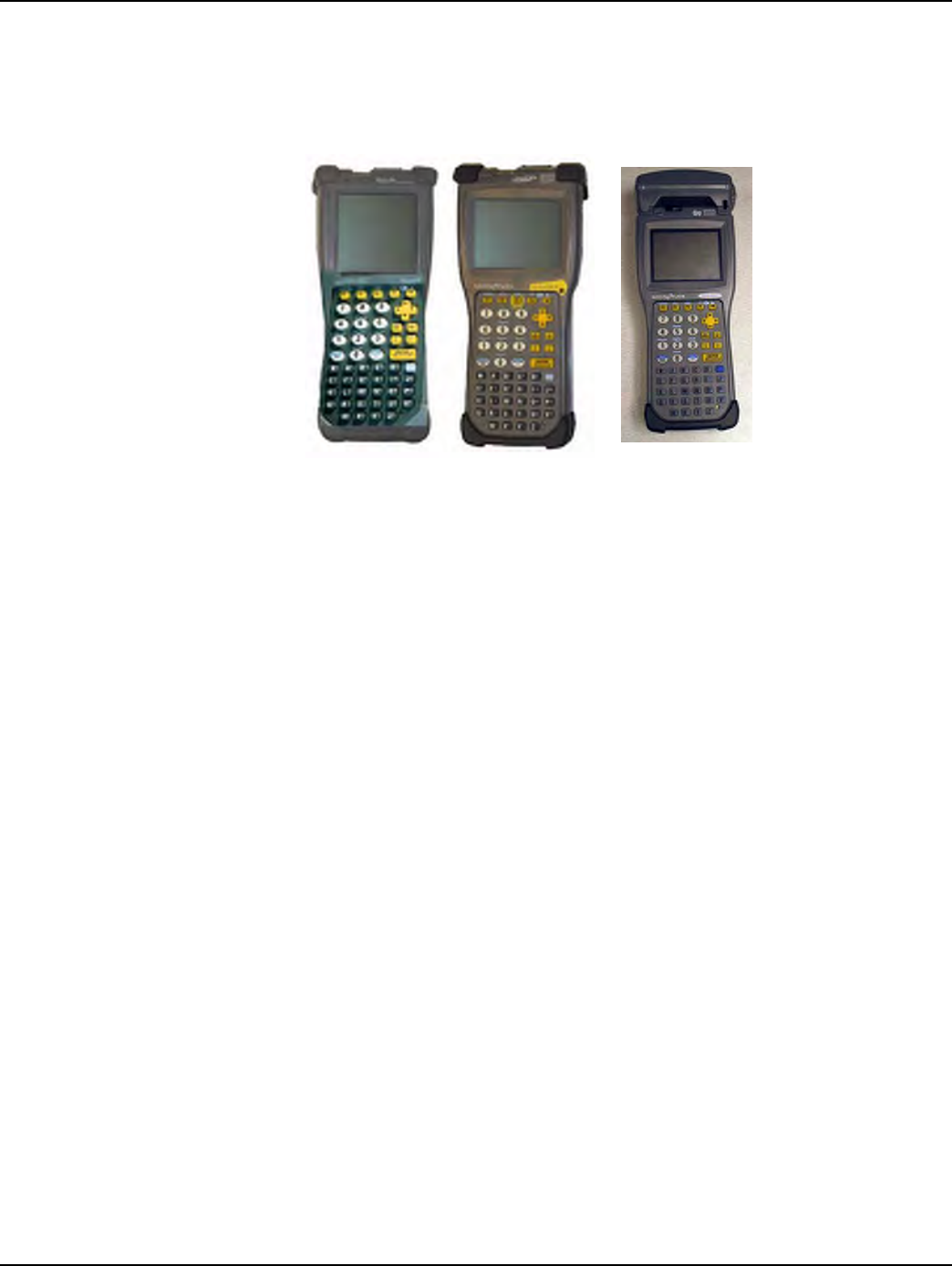
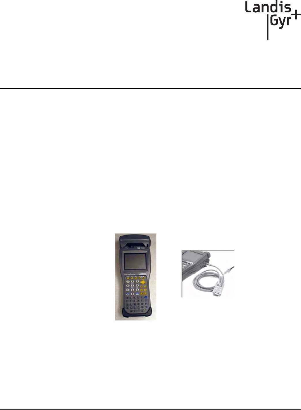
Figure 2 - 2. Handhelds with programming cables
Handhelds differ by program, but the ones shown above are currently in service. On the left is the
DAP PC9800, a DOS-based Handheld. In the middle is the DAP CE5320, a Windows CE-based
Handheld. On the right is the DAP CE5320b, a Windows CE-based Handheld.
Install Material
The Gas Meter Exchange process consists of using predetermined route information that identifies
the meters that need to be retrofitted with the Landis+Gyr Gas Meter Module and methods for
recording data to document the installation. The route information describing the account address,
existing meter ID, estimated meter reads, and any special instructions that describe circumstances
unique to that particular account will reside in the installers Handheld.
From the Cross Dock, obtain your Handheld and the Meter Modules to be installed. The Handheld
will be preloaded by the Cross Dock with all of the data for the assigned routes. The pre-loaded data
includes the route, address, meter ID, and estimated read for the particular meters, plus specific
instructions and required field collects information.
Each installer must validate that the handheld is properly loaded with the correct route information
before leaving the Cross Dock.
Chapter 2 - Pre-Installation Landis+Gyr
10 98-3107 Rev AA One-way Gas Module Installation Guide
Meter Compatibility
This Gas meter Compatibility List is the result of retrofit experience and feedback from American
Meter.
Every attempt has been made to ensure the accuracy of the information in this table. There may be
limitations to compatibility unknown to Landis+Gyr due to changes made which L+G has been
unable to document through our research and substantial meter library. Any questions about the
compatibility information should be forwarded to your L+G representative.
Supported Odometer and Metal Indexes
Table 2-2. Gas Meter Compatibility List
jçÇÉä pí~êí=
vÉ~ê
båÇ=vÉ~ê aêáîÉ m~êí=@=ïL=ëíÇK=
Ä~ííÉêó
é~êí@=ïL=ÜáÖÜ=
Å~é~Åáíó=Ä~ííÉêó
^i=NTR NVRU NVVP NÛ=L=OÛ OSJMMSU OSJNMTQ
^i=ORM NVSS NVUR OÛ OSJMMSU OSJNMTQ
^i=PNM NVTV NVUR OÛ OSJMMSU OSJNMTQ
^i=QOR NVSR `ìêêÉåí OÛ OSJMMSU OSJNMTQ
^q=ORM NVSU `ìêêÉåí NÛ=L=OÛ OSJMMSU OSJNMTQ
^q=PRM NVVU `ìêêÉåí OÛ OSJMMSU OSJNMTQ
^`=NTR NVSR `ìêêÉåí NÛ=L=OÛ OSJMMSU OSJNMTQ
^`=ORM NVTS `ìêêÉåí NÛ=L=OÛ OSJMMSU OSJNMTQ
^`=SPM NVVU `ìêêÉåí OÛ OSJMMSU OSJNMTQ
^j=ORM NVUR `ìêêÉåí NÛ=L=OÛ OSJMMSU OSJNMTQ
Except for the AC-250, meters with the odometer-type dial on any of the models above are
not supported.
Table 2-3. Odometer and Metal indexes
eçìëáåÖ =_lj máå=qóéÉ fåÇÉñ=qóéÉ oÉÑÉêÉåÅÉ
OVJNMSTJN OSJNOPT pÜçêí=éáå lÇçãÉíÉê q^I=d~ëiuI=
oÉëáÇÉåíá~äI=^ãÉêáÅ~å=
OVJNMSTJO OSJNOMQ içåÖ=éáå mä~ëíáÅ q^I=d~ëiuI=
oÉëáÇÉåíá~äI=^ãÉêáÅ~å=

Landis+Gyr Chapter 2 - Pre-Installation
One-way Gas Module Installation Guide 98-3107 Rev AA 11
Compliance
This apparatus is suitable for Class I, Division 1, Group D Hazardous Locations.
Safety and Environment
Prerequisite Training
Installers should be instructed in the following safety elements as well as any site-specific safety
issues:
• Hazard Communication (Employee Right to Know)
• Lifting
• Safe driving
• Use of hand tools
• Confined space
Preliminary Checks
The installer should already be able to operate the HandHeld computer. Additionally, you should
already have route information and the required number of endpoints.
• Verify that you are at the correct site, specified on the handheld computer or work order.
• Verify that the site is safe for you and your equipment.
• Notify the customer of your presence. Tell the customer that you must have access to the water
meter. If necessary, have the customer sign the work order.
• When installing meters, follow any guidelines issued by your company in addition to those
given in this guide.
• Never perform an installation during a lightning storm or under excessively wet conditions.
Site Requirements
The site must comply with the following criteria:
• There is no chance that another object will be set over the antenna.
• Some instances may require additional cable.
• Maximum cable length is always 200 feet.
Warning - Explosion Hazard - Substitution of components may impair suitability for
Class I, Division 1.

Chapter 2 - Pre-Installation Landis+Gyr
12 98-3107 Rev AA One-way Gas Module Installation Guide
FCC & Industry Canada Information to the User
Manufacturer: Cellnet
Model Name: GasLX
FCC ID: R7PGRAMCNLX1
IC: 5294A-GRAMCNLX1
This device complies with Part 15 of the FCC rules. Operation is subject to the following two
conditions:
1Thisdevicemaynotcauseharmfulinterference,and
2Thisdevicemustacceptanyinterferencereceived,includinginterferencethatmaycause
undesiredoperation.
FCC Class B
This equipment has been tested and found to comply with the limits for a Class B digital device,
pursuant to Part 15 of the FCC Rules. These limits are designed to provide reasonable protection
against harmful interference in a residential installation. This equipment generates, uses, and can
radiate radio frequency energy and, if not installed and used in accordance with the Instructions, may
cause harmful interference to radio communications. However, there is no guarantee that
interference will not occur in a particular installation. If this equipment does cause harmful
interference to radio or television reception, which can be determined by turning the equipment off
and on, the user is encouraged to try to correct the interference by one or more of the following
measures:
• Reorient or relocate the receiving antenna.
• Increase the separation between the equipment and receiver.
• Consult Cellnet or an experienced radio technician for help.
RF Exposure
In accordance with FCC requirements of human exposure to radio frequency fields, the radiating
element shall be installed such that a minimum separation distance of 20 centimeters will be
maintained.
Changes or modifications to this device not expressly approved by Cellnet
Technology, Inc. could void the user's authority to operate the equipment.

Landis+Gyr Chapter 2 - Pre-Installation
One-way Gas Module Installation Guide 98-3107 Rev AA 13
Notes:
14 One-way Gas Module Installation Guide
Pre-Installation
3
One-way Gas Module Installation Guide 98-3107 Rev AA 15
Using the HandHeld Device
The DAP 5320b is a portable and rechargeable HandHeld computer unit. Its electric components are
protected in hard plastic housing.
The features of the DAP 5320B include
• Windows-CE-based color LCD display
• Alphanumeric keypad
• Integrated barcode scanner
• 7-pin LEMO is used for charging the HandHeld or uploading/downloading from RIMS
• Automatic shutoff to maximize battery life
• Hand strap for secure handling.
The Handheld PC (the “Handheld”) communicates with a desktop or laptop computer through a
communications cradle and a 7-pin LEMO charging/communications cable. It is configured to
receive and transmit installation and manual meter read data to and from the RIMS and OCDB
databases. The communications cradle and cable are also used for recharging (approximately 2.5
hours needed for full charge).
Figure 3 - 1. DAP PC5320B Hand Held PC and LEMO callout
Manufacturer Documentation
For more detail, visit the DAP website at https://www.daptech.com/docudap/.
Chapter 3 - Using the HandHeld Device Landis+Gyr
16 98-3107 Rev AA One-way Gas Module Installation Guide
Display
The DAP Handheld uses a TFT liquid crystal display (LCD).
Figure 3 - 2. CE Display
High-contrast characters are easily visible in normal light. Instructions for each screen display at the
top of each screen in blinking red letters. The Handheld displays a tabbed view where you advance
one screen at a time. You can go back as many screens as you want.
Landis+Gyr Chapter 3 - Using the HandHeld Device
One-way Gas Module Installation Guide 98-3107 Rev AA 17
Keyboard
The keys on the keyboard are labeled with primary functions (such as: I/O (PWR), ESC, SP, BKSP),
the 26-character alphabet, 0-9 numbers, and various symbols. Enter data by pressing the appropriate
key. Enter other functions by pressing the FUNC (blue) key first, then pressing the corresponding
alphanumeric keys.
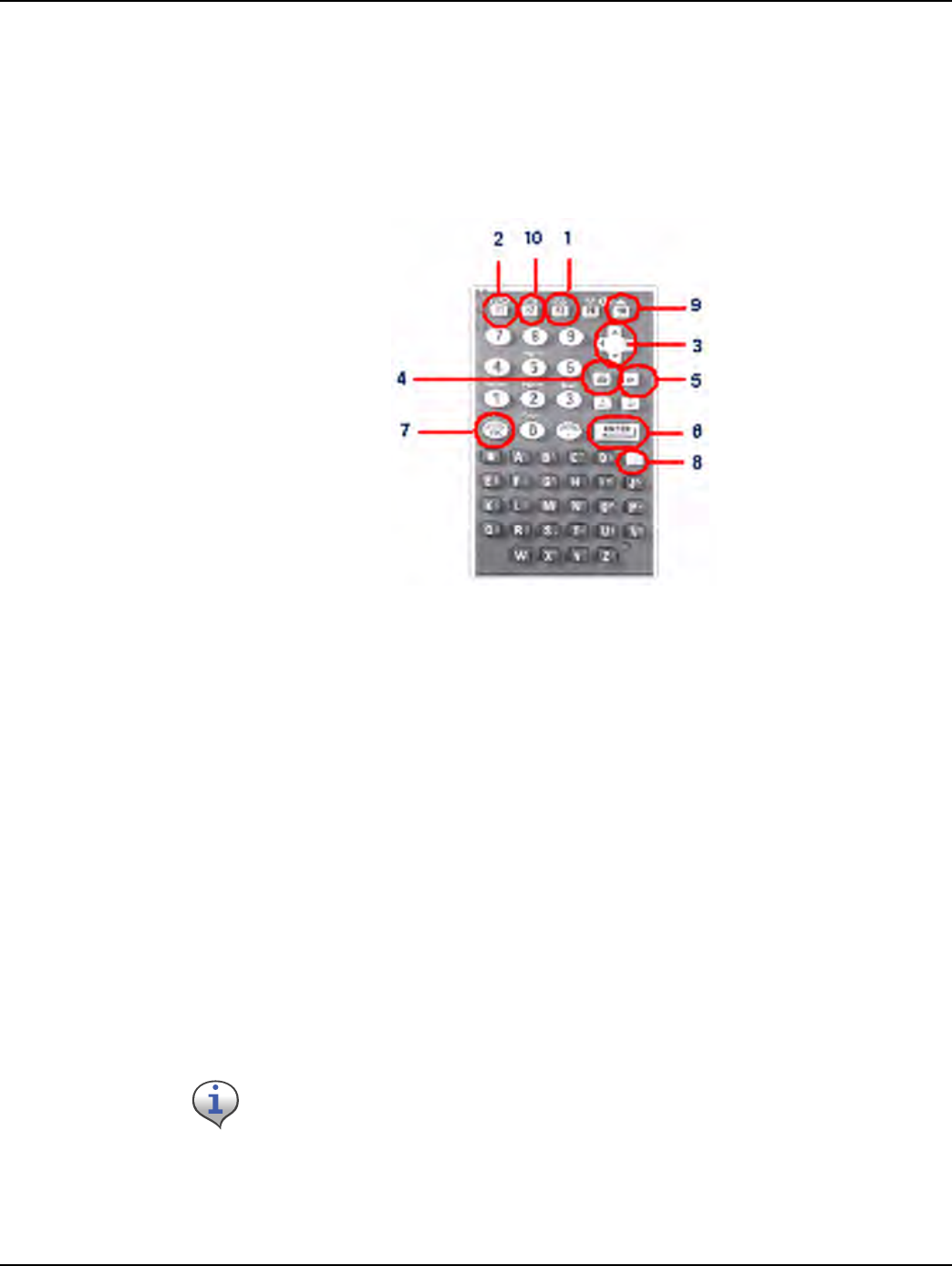
Figure 3 - 3. DAP Keypad
1SCANButton:smallyellowF3key;initiatesscanofbarcode
2I/O /F1powerkey;turnsuniton‐FUNCthenF1turnstheunitoff
3ArrowCursorPadkey:changesselection,tabsup,down,leftorright
4BKSP:eraseslastcharacterenteredduringtextentry
5SP:addsspacetotextentry
6ENTER:entersfunction;savesentryandexitsfunction
7ESC:displayspreviousscreen
8FUNC+Key:bluecoloredfunctionkeyincombinationwithotherkeysallowstheusertoenter
non‐alphacharacters,adjustthecontrast,turnonthebackgroundlight,etc.
Entry Keys: alphanumeric characters (A-Z, 0-9)
CTRL/ALT: not used
9Tabkey:changesselection
10 F2:Displayscurrentbatterylife
You can shut off the Handheld PC during installation with the automatic shutoff feature or
by pressing FUNC + F1 (PWR) key. The unit retains existing data and recalls the last step
performed when it is turned on again.
Automatic shutoff is a sleep function. The unit shuts off after 3 minutes of inactivity. To turn
on the Handheld PC after automatic shutoff, press the F1 key.

Chapter 3 - Using the HandHeld Device Landis+Gyr
18 98-3107 Rev AA One-way Gas Module Installation Guide
Program Conventions
• Keys are active for the displayed function. For example, if text is required, the alphanumeric
keys are active; if a display option is to be selected, the Arrow Cursor Pad may be used as a tab
key. If there is a list or drop-down type menu, there will be small arrows on the screen indicating
that the Arrow Cursor Pad should be used for the selection.
• Most display options can be selected by pressing the hotkey (key corresponding to the first
capital letter in the option). For example, N is the hotkey to select iNfo in the address screen.
Pressing the hotkey is equivalent to tabbing to that item and pressing “enter”.
• A hotkey that is not indicated in the on-screen text and is available on the “Functions” menu
screen is: T - this takes you to the Date/Time menu.
• The following keys are available at most screens:
ARROWCURSORPAD‐Advancestothenextoption
ENTER‐Selectsandentersthehighlightedoption
ESC‐Exitscurrentfunctionandreturnstopreviousfunction
TAB KEY‐Advancestothenextoption
• Other program conventions specific to a particular function are described in the appropriate
section.
Using the DAP Handheld
This section goes through the process of using a DAP Handheld when installing a Landis+Gyr-
ready meter at a customer account.
Getting Started with the Handheld
A typical gas meter installation route consists of the following basic steps:
1Checkoutmeterswithmodulesalreadyinstalledandmetermodulesforretrofit.Pickup
HandheldPCandlabels.Priortometercheckout,theHandHeldPCisprogrammedforan
assignedinstallerandaninstallationroute(accountaddress,currentmeterID,meterlocation,
etc.).
2Checkroute.ReviewinstallerIDroutestatus:numberofinstallationsperrouteID,installations
completedorskipped.
3Checkaccountaddress.Verifyaddressandanyspecialcustomerinformationuponarrivalatthe
customersite.
4CheckMeterID.VerifythatthemeterIDmatchestheoneintheHandheld.
5Entermeterread.Entermeterreadingfromexistingmeter.
6ScanmeterID.ScanmeterIDfromthechangeoutmeterlabels.
7Toinstallchangeoutmeter,labelexistingmeterwithachangeoutlabel,removeexistingmeter,
andreplacewithchangeoutmeter.
8 Repeatsteps3to7foreachaddress.
9Checkinreplacedmeters.ReturnthemtotheCross‐DockanddocktheHandheldPC.
Landis+Gyr Chapter 3 - Using the HandHeld Device
One-way Gas Module Installation Guide 98-3107 Rev AA 19
Standard Meter Installation and/or Module Retrofit
This section covers the installer steps and Handheld screens for the meter exchange process or gas
module retrofit.
Check Route Status
1StarttheHandheldPCbypressingtheI/O /F1powerkey.Thescreenbelowdisplays.Ifthis
screendoesnotdisplay,pressEnterorESCkeystogettotheCustomerAddressscreen.
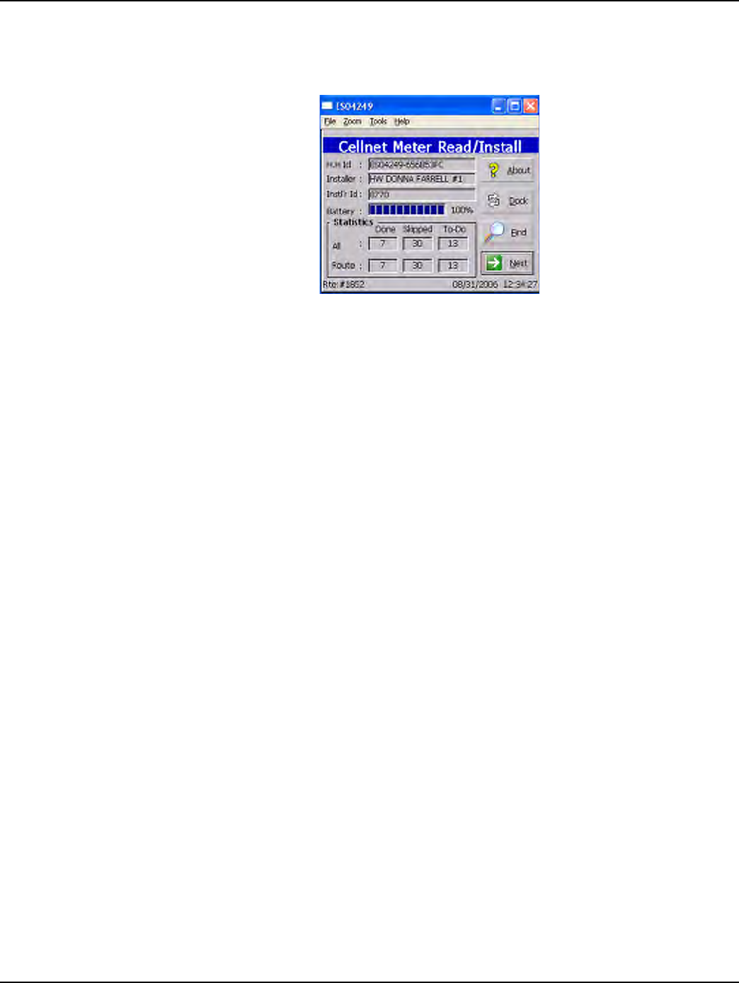
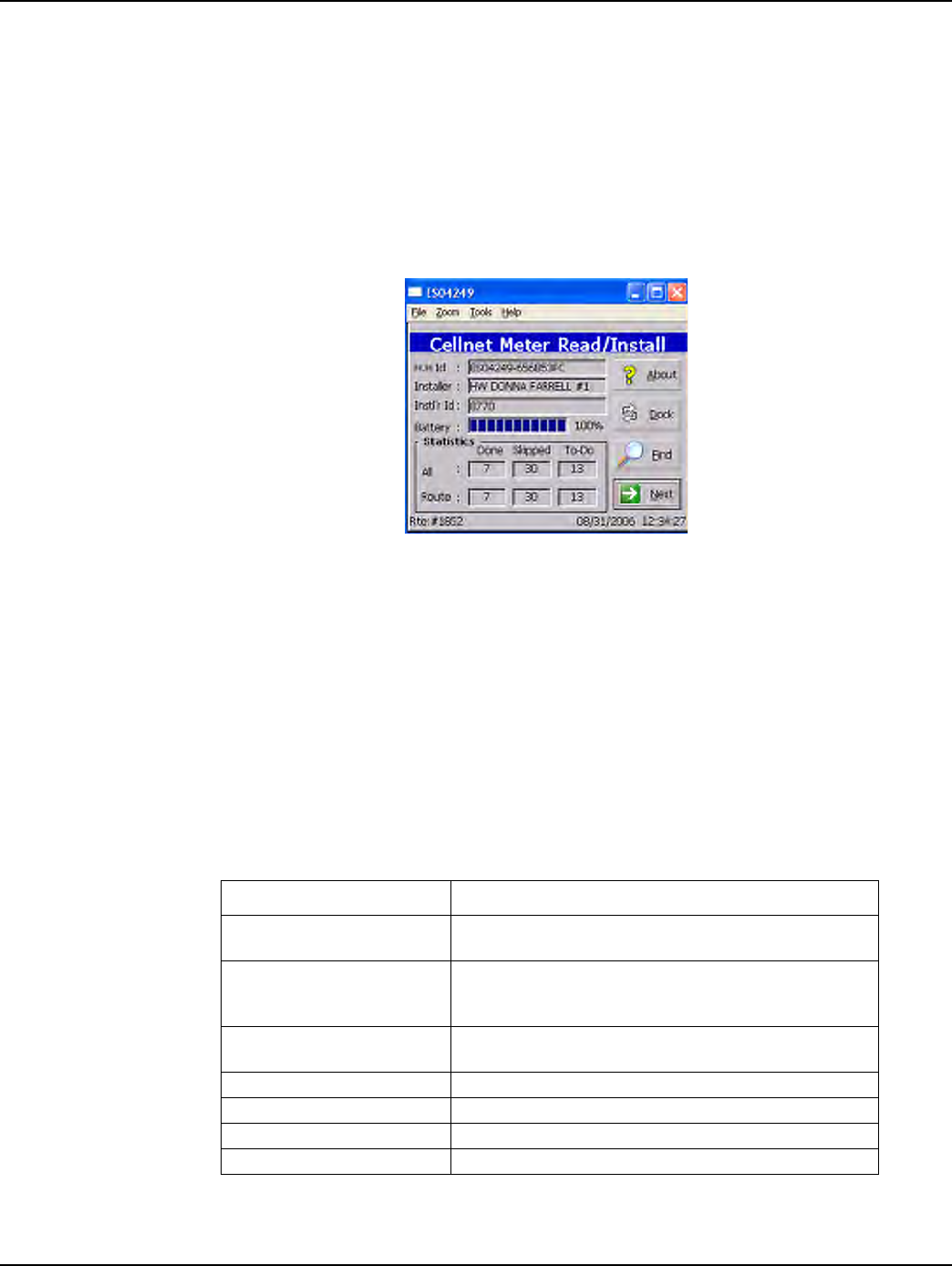
Figure 3 - 4. Handheld main screen
Initial boot screen displays the first work order’s information:
• Handheld ID
• Installer name
• Installer ID
• Battery information
• Total route statistics
• Current route number
Table 3-1. Handheld Options and Active Keys for Check Route Status
Option or Active Key Function
^Äçìí aáëéä~óë=áåÑçêã~íáçå=~Äçìí=íÜÉ=ãÉíÉê=áåëí~ää=ëçÑíï~êÉ=
áåÅäìÇáåÖ=îÉêëáçåI=ÅçéóêáÖÜíI=~åÇ=ãçÇìäÉë=áåëí~ääÉÇ
açÅâ båÇë=áåëí~ää~íáçå=éêçÅÉëëX=~ää=áåëí~ää~íáçåë=~êÉ=ÅÜÉÅâÉÇK=fÑ=
ëçãÉ=áåëí~ää~íáçåë=~êÉ=åçí=ÅçãéäÉíÉÇI=~=ãÉëë~ÖÉ=~ééÉ~êë=
íç=îÉêáÑó=íÜ~í=óçì=ï~åí=íç=ÇçÅâK
cáåÇ ^ääçïë=íÜÉ=áåëí~ääÉê=íç=ëÉ~êÅÜ=Ñçê=~=é~êíáÅìä~ê=~ÅÅçìåí=Äó=
~ÇÇêÉëëI=ãÉíÉê=faI=ÅìëíçãÉê=å~ãÉI=çê=~ÅÅçìåí=åìãÄÉêK
kÉñí pÉäÉÅíë=íÜÉ=åÉñí=çéíáçå
^êêçï=`ìêëçê=m~Ç eáÖÜäáÖÜíë=íÜÉ=åÉñí=çéíáçå
båíÉê p~îÉë=~åó=ÅÜ~åÖÉë=~åÇ=~Çî~åÅÉë=íç=íÜÉ=åÉñí=ëÅêÉÉåK
bp` bñáíë=íÜÉ=~ééäáÅ~íáçåK
Chapter 3 - Using the HandHeld Device Landis+Gyr
20 98-3107 Rev AA One-way Gas Module Installation Guide
4PressEntertodisplayfirstaddressfordisplayedroute.
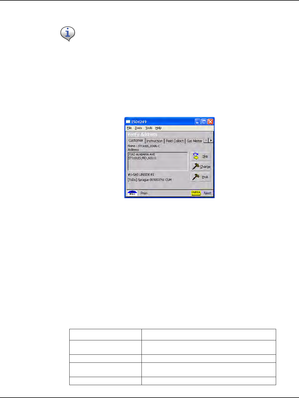
Check Address
The address screen shows the account’s address and any other information pertinent to the
installation process. If there are special instructions for the account, the screen displays an
instructions prompt; otherwise, a standard address screen displays.
Figure 3 - 5. Handheld Address with special instructions
The Customer screen displays:
• Address information
• Sequence number in list of meters (#1 is first meter to be installed)
• Meter type (for example, gas meter)
• Meter location (Lxx or Lxxx, where xx or xxx is the utility-specific location code (for example
L01)
• Read instruction code (R1xx, where xx is the utility-specific read) instruction code (for example
RI00)
• Meter ID status of this record (ToDo, Skipped, or Completed)
The Handheld PC can be shut off during installation with the automatic shutoff feature or by
pressing the FUNC and then the I/O / F1 power key The unit retains existing data and
remains at the last step performed until it is turned on again and additional data is entered.
Table 3-2. Handheld Options and Active Keys for Route Status screen
Option or Active Key Function
fåëíêìÅíáçåë aáëéä~óë=íÉñí=áåÑçêã~íáçå=~Äçìí=íÜÉ=~ÅÅçìåí=E_~Ç=ÇçÖI=oáåÖ=
ÇççêÄÉääI=ÉíÅKF
pâáé pâáéë=íÜÉ=ÅìêêÉåí=ïçêâ=çêÇÉê
`Ü~åÖÉ léÉåë=íÜÉ=`Ü~åÖÉ=ëÅêÉÉå=íç=ìéÇ~íÉ=ÇÉí~áäë=~Äçìí=íÜÉ=
~ÅÅçìåí
mêçÄ léÉåë=íÜÉ=mêçÄäÉã=ëÅêÉÉå=ïáíÜ=~=äáëí=çÑ=ìé=íç=Q=éêçÄäÉãë
Landis+Gyr Chapter 3 - Using the HandHeld Device
One-way Gas Module Installation Guide 98-3107 Rev AA 21
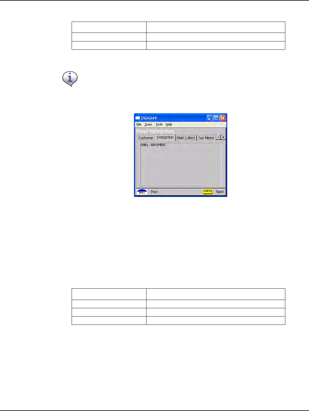
1PressENTERtoviewinstructions.
Figure 3 - 6. Handheld special instructions screen
Special instructions may include:
• Meter location
• Customer’s medical condition
• Hazardous situation (guard dog, etc.).
4PressEnter.TheUtilityFieldDataCollectionortheDialReadEntryscreendisplays.
bp` oÉíìêåë=íç=íÜÉ=mêÉîáçìë=ëÅêÉÉå
båíÉê p~îÉë=ÅÜ~åÖÉë=~åÇ=~Çî~åÅÉë=íç=íÜÉ=åÉñí=ëÅêÉÉå
If the address or instructions exceed the length of the window, vertical scroll bars display.
Arrow Cursor Pad moves the display up or down.
Table 3-3. Handheld Options and Active Keys for Special Instructions
Option or Active Key Function
båíÉê ^Çî~åÅÉë=íç=íÜÉ=åÉñí=ëÅêÉÉå
^êêçï=`ìêëçê=m~Ç eáÖÜäáÖÜíë=ÅäáÉåík~ãÉ
bp` bñáíë=íÜÉ=~ééäáÅ~íáçå
Table 3-2. Handheld Options and Active Keys for Route Status screen
Option or Active Key Function
Chapter 3 - Using the HandHeld Device Landis+Gyr
22 98-3107 Rev AA One-way Gas Module Installation Guide
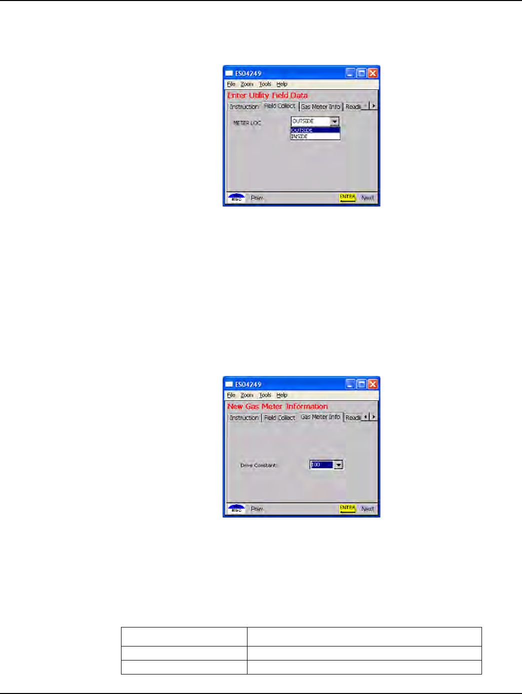
Utility Field Data Collection
Figure 3 - 7. Handheld Utility Field Data screen
This screen varies—or is not used—depending on the utility. In this example, the utility company
requires a description of meter location.
1SelecttherelevantoptionandpresstheEnterkey.
Meter Information
After pressing Enter, the Handheld PC displays the following prompts for drive constant and meter
reading.
Figure 3 - 8. Handheld Dial read entry screen
The meter information screen displays various options for drive constant (also known as the meter
constant or drive quantity). Residential gas meters have a drive constant of 1 or 2 (default value).
.
Table 3-4. Handheld Options and Active Keys for Meter Reading
Option or Active Key Function
aêáîÉ=`çåëí~åí båíÉêë=ÇêáîÉ=Åçåëí~åíK
^êêçï=`ìêëçê=m~Ç eáÖÜäáÖÜíë=íÜÉ=åÉñí=çéíáçå
Landis+Gyr Chapter 3 - Using the HandHeld Device
One-way Gas Module Installation Guide 98-3107 Rev AA 23
1Selecttheappropriatedriveconstant.
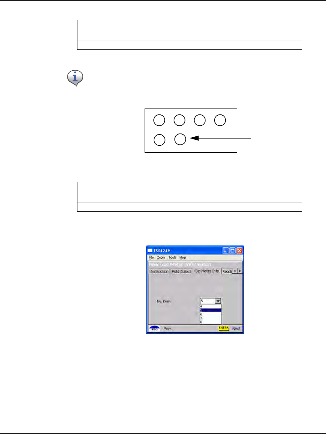
Figure 3 - 9.
Generic Meter Dial Configuration
4PressEnter.TheHandheldPCdisplaysthefollowingpromptsformeterreading.
Figure 3 - 10. Handheld number of dials selection screen
• The meter information screen displays the following options for the number of reading dials: 4,
5, or 6.
båíÉê p~îÉë=~åó=ÅÜ~åÖÉë=~åÇ=~Çî~åÅÉë=íç=íÜÉ=åÉñí=ëÅêÉÉåK
bp` oÉíìêåë=íç=íÜÉ=êçìíÉ=ëí~íìë=ëÅêÉÉå
Installer must verify that the drive constant is equivalent to the dial cubic foot as indicated
below.
Table 3-5. Drive Constant Selection
Drive Constant Dial Type
OO=Ñççí=Çá~ä
NN=Ñççí=Çá~ä
Table 3-4. Handheld Options and Active Keys for Meter Reading
Option or Active Key Function
Dial
Chapter 3 - Using the HandHeld Device Landis+Gyr
24 98-3107 Rev AA One-way Gas Module Installation Guide
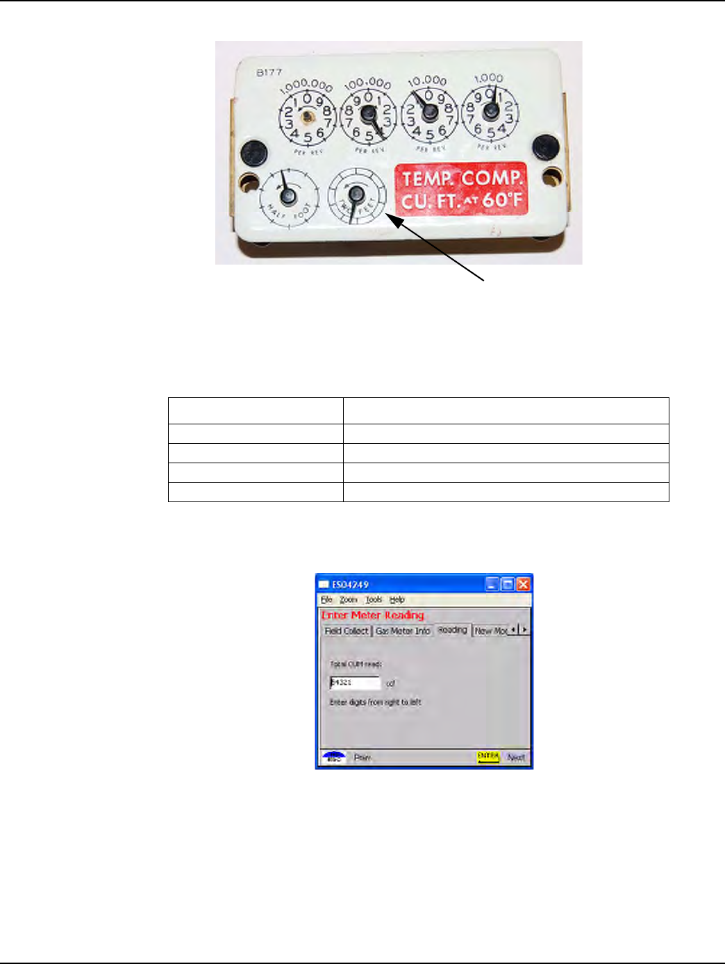
• The first dial counted is the 1,000 CF/rotation. Count up to the highest dial.
Figure 3 - 11. Handheld Start counting dials
The Numeric field is highlighted for manual entry of meter reading from existing meter.
Figure 3 - 12. Handheld dial read entry screen
The meter reading is sometimes validated based on utility parameters, such as:
• Previous reading
• Read date
• Expected rate (ccf/day)
Table 3-6. Handheld Options and Active Keys for Number of Dials selection
Option or Active Key Function
kçK=çÑ=aá~äë aáëéä~óë=Çá~ä=ÅçìåíK
^êêçï=`ìêëçê=m~Ç eáÖÜäáÖÜíë=íÜÉ=åÉñí=çéíáçå
båíÉê p~îÉë=~åó=ÅÜ~åÖÉë=~åÇ=~Çî~åÅÉë=íç=íÜÉ=åÉñí=ëÅêÉÉåK
bp` oÉíìêåë=íç=íÜÉ=êçìíÉ=ëí~íìë=ëÅêÉÉå
START HERE
Landis+Gyr Chapter 3 - Using the HandHeld Device
One-way Gas Module Installation Guide 98-3107 Rev AA 25
• Allowable percentage variation (utility specific).
If this check is not in place you will be prompted to enter the last four numbers of the meter ID and
to re-enter the read.
.
1Enterreadingforexistingmeterinmeterreadscreen.Entervaluesfromrighttoleft.
2PressEnter.Youarenowreadytoscanthechangeoutlabel.
Program the Meter Module
The following steps apply to both a meter exchange or a module retrofit. New meters with modules
do not require programming.
Begin installing the gas module by following the instructions in later chapters of this Guide.
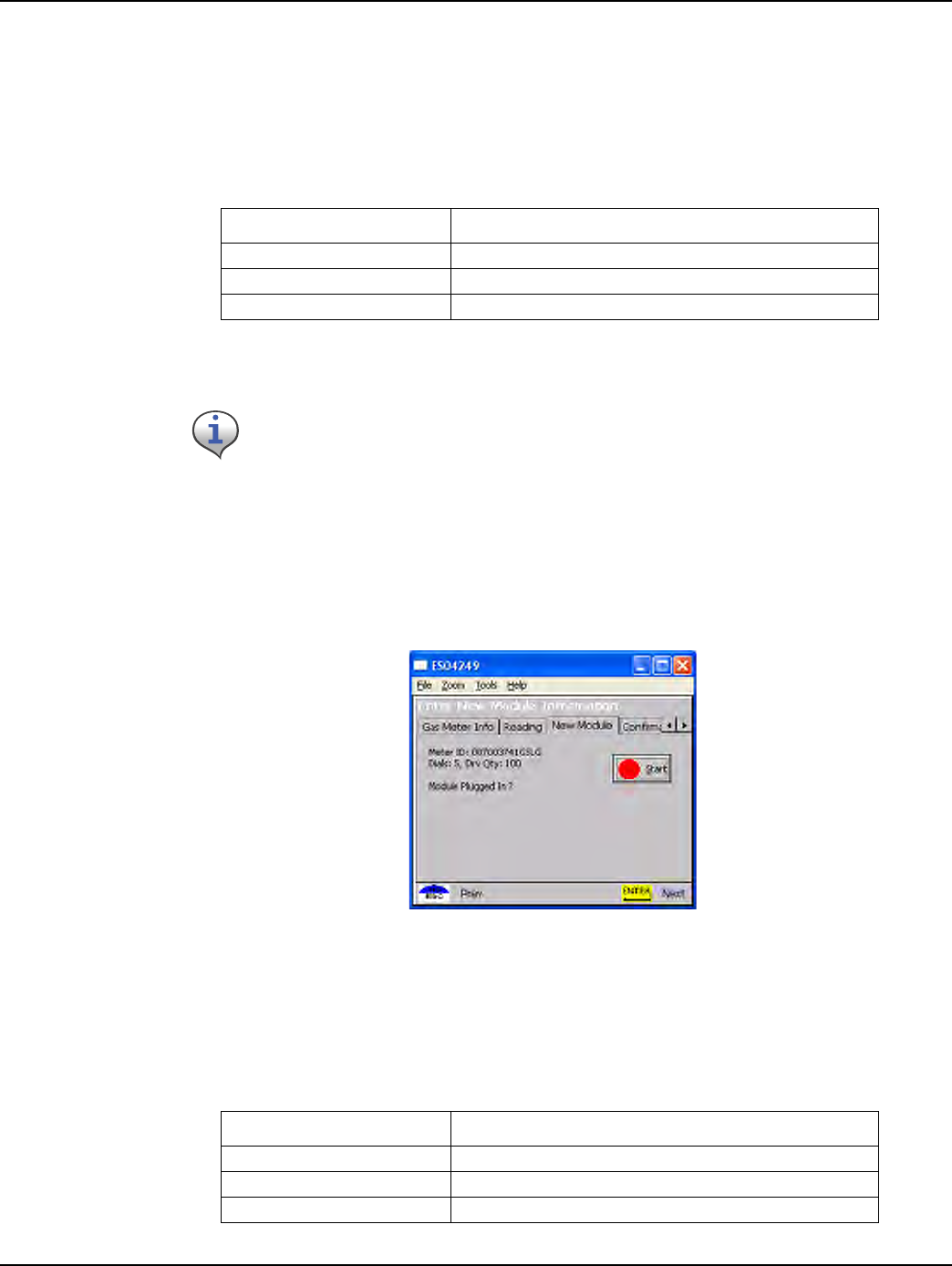
Figure 3 - 13. Handheld Initial programming screen
Program screen displays the meter information and prompts the installer to connect to the meter
module.
.
Table 3-7. Handheld Options and Active Keys for Meter Reading
Option or Active Key Function
MJV båíÉêë=êÉ~ÇK
båíÉê p~îÉë=~åó=ÅÜ~åÖÉë=~åÇ=~Çî~åÅÉë=íç=íÜÉ=åÉñí=ëÅêÉÉåK
bp` oÉíìêåë=íç=íÜÉ=êçìíÉ=ëí~íìë=ëÅêÉÉå
If the meter reading does not pass validation, refer to the section on Meter Reading Out of
Range.
Table 3-8. Handheld Options / Active Keys for initial programming screen
Option or Active Key Function
pí~êí _ÉÖáåë=éêçÖê~ããáåÖ=íÜÉ=ãçÇìäÉ
båíÉê p~îÉë=~åó=ÅÜ~åÖÉë=~åÇ=~Çî~åÅÉë=íç=íÜÉ=åÉñí=ëÅêÉÉåK
bp` oÉíìêåë=íç=íÜÉ=éêÉîáçìë=ëÅêÉÉå
Chapter 3 - Using the HandHeld Device Landis+Gyr
26 98-3107 Rev AA One-way Gas Module Installation Guide
1 ConnecttheHandheldPCtothemetermodule(refertoappropriateinstallationprocedure).
2ChecktoensurethattheinformationthatyouenteredintotheHandheldiscorrect,suchasdrive
constant,Indexread,andmeterID.Forexample,dials=4,meterID=0123456G,meterconstant=2.
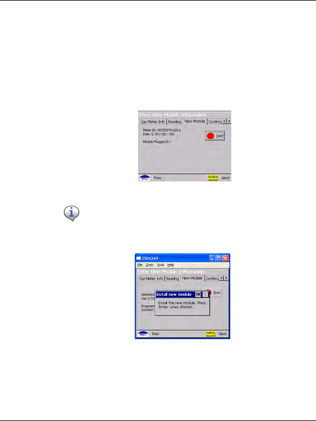
3PressENTERtobeginprogrammingthemetermodule.TheHandheldPCwilldisplaythe
followingscreensduringprogramming:
The Handheld PC searches for the connected meter module. This process will take a few seconds.
If the meter module is not connected, an error screen displays. Refer to "Special Cases" on page -27
for more information.
The meter information is downloaded to the meter module. This process takes a few seconds.
Figure 3 - 14. Handheld Enter New Module Information screen
Figure 3 - 15. Handheld Install complete
Confirmation that program has loaded.
Always enable tamper notification.
Landis+Gyr Chapter 3 - Using the HandHeld Device
One-way Gas Module Installation Guide 98-3107 Rev AA 27
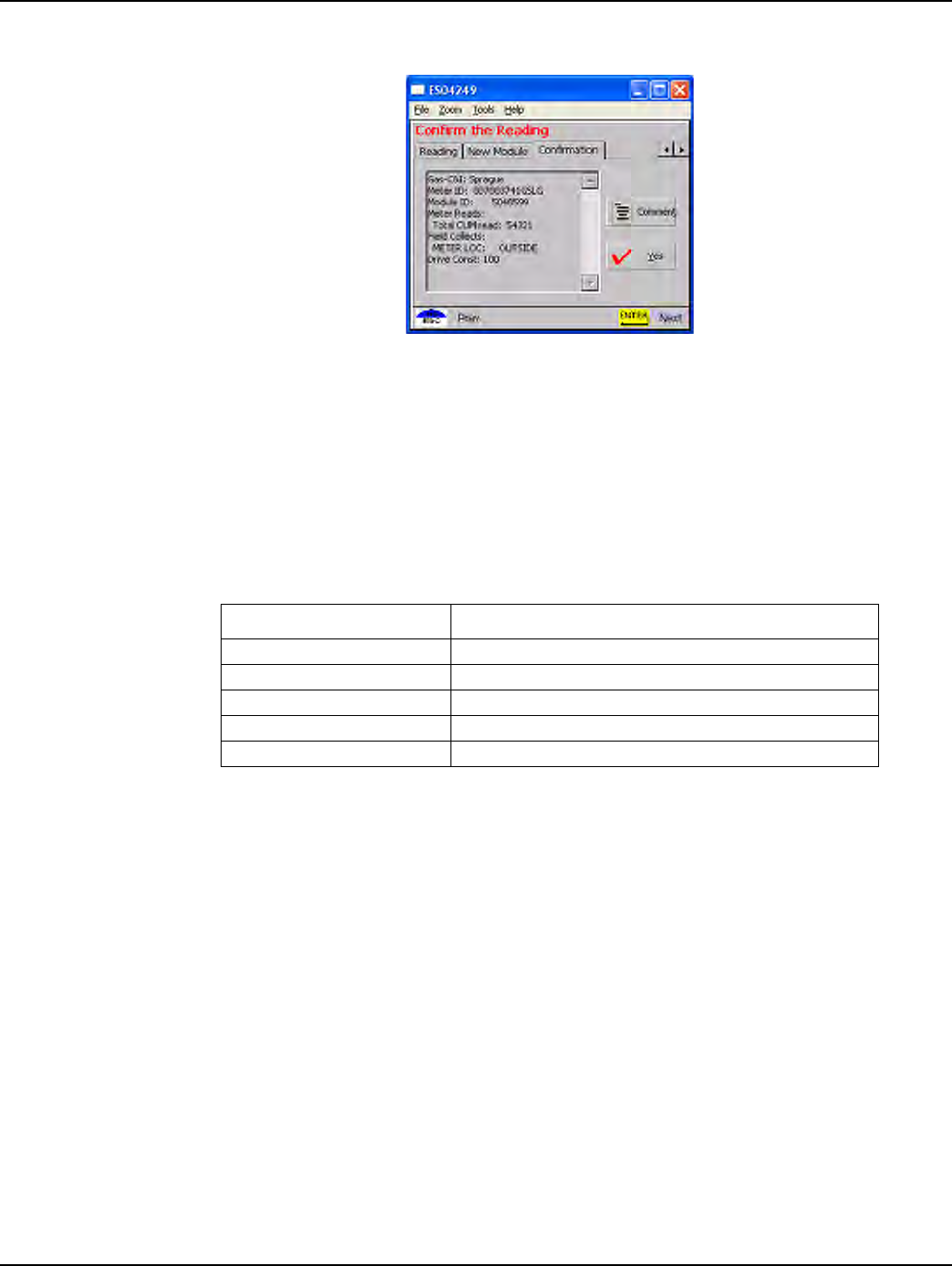
Figure 3 - 16. Handheld redisplays information
Meter information redisplays to verify the meter read and meter ID.
.
Special Cases
This section details causes of problems during an installation. However, this list may not cover all
issues.
Meter Reading Out of Range
If the meter reading is out of range during standard meter installation, the software prompts for
additional information (enter last four digits of meter ID, re-enter meter read, change meter ID if
different that expected) before allowing meter installation.
1VerifymetertypeandID.
aEntertheexistingmeterserialnumberintheHandheld.
bVerifytheexistingmeterserialnumbermatchestheexistingmeterserialnumberinthe
Handheld.
—Iftheexistingmeterserialnumberdoesnotmatchtheexistingmeterserialnumber,
intheHandheld,verifytheaddress.
Table 3-9. Handheld Options and Active Keys for Programming the Meter Module
Option or Active Key Function
vÉë ^ÅÅÉéíë=ãÉíÉê=êÉ~ÇáåÖ=~åÇ=ÅçåíáåìÉë=íç=åÉñí=~ÇÇêÉëë
kç oÉíìêåë=íç=íÜÉ=ÄÉÖáååáåÖ=çÑ=íÜÉ=ÅìêêÉåí=~ÇÇêÉëë
`çããÉåí båíÉê=áÑ=êÉèìáêÉÇ
båíÉê p~îÉë=~åó=ÅÜ~åÖÉë=~åÇ=~Çî~åÅÉë=íç=íÜÉ=åÉñí=ëÅêÉÉå
^êêçï=`ìêëçê=m~Ç eáÖÜäáÖÜíë=çéíáçåë=vÉëLkç
Chapter 3 - Using the HandHeld Device Landis+Gyr
28 98-3107 Rev AA One-way Gas Module Installation Guide
2Performtechnicalreviewofmeter.
EntertheappropriatecodeinyourHandheld,andthencallyourSupervisorforsupport.
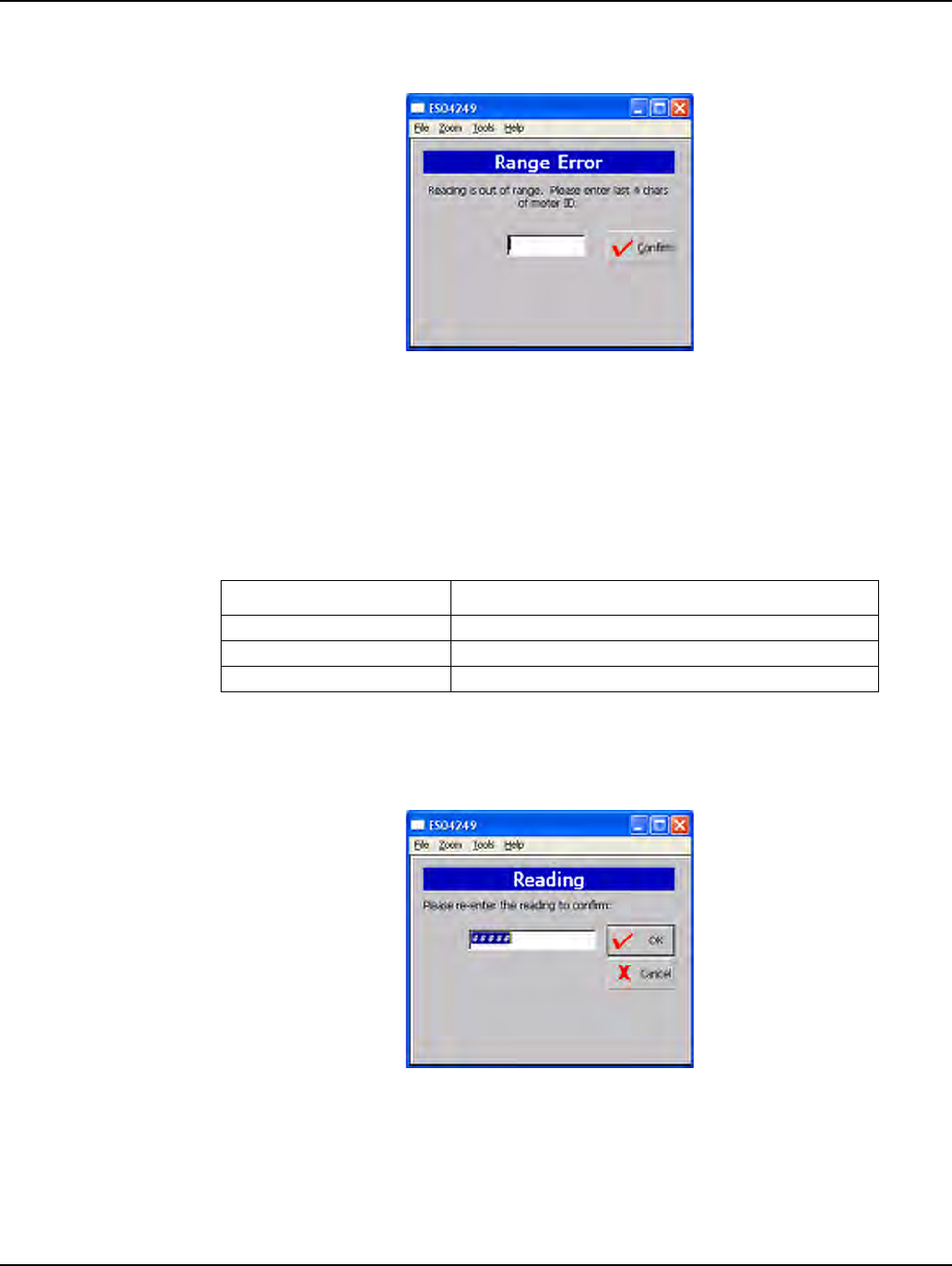
Figure 3 - 17. Handheld Read out of Range screen
The software requests the last four numbers of existing meter ID to confirm that the meter belongs to
this account. If meter ID does not match, the account address is redisplayed for verification or
depending on utility, specific instructions display.
.
4EnterthelastfourdigitsoftheexistingmeterID.Thesoftwarerequestsverificationofthemeter
read.Thishelpstoconfirmthattheinstallerisattherightlocation.
Figure 3 - 18. Handheld Re-enter meter read
Table 3-10. Handheld Options and Active Keys for Read Out of Range
Option or Active Key Function
^JwI=MJV båíÉêë=íÜÉ=ãÉíÉê=fa
båíÉê p~îÉë=~åó=ÅÜ~åÖÉë=~åÇ=~Çî~åÅÉë=íç=íÜÉ=åÉñí=ëÅêÉÉå
bp` oÉíìêåë=íç=ãÉíÉê=êÉ~Ç=ëÅêÉÉå
Landis+Gyr Chapter 3 - Using the HandHeld Device
One-way Gas Module Installation Guide 98-3107 Rev AA 29
.
4Re‐entermeterreading.
Meter ID Confirmation
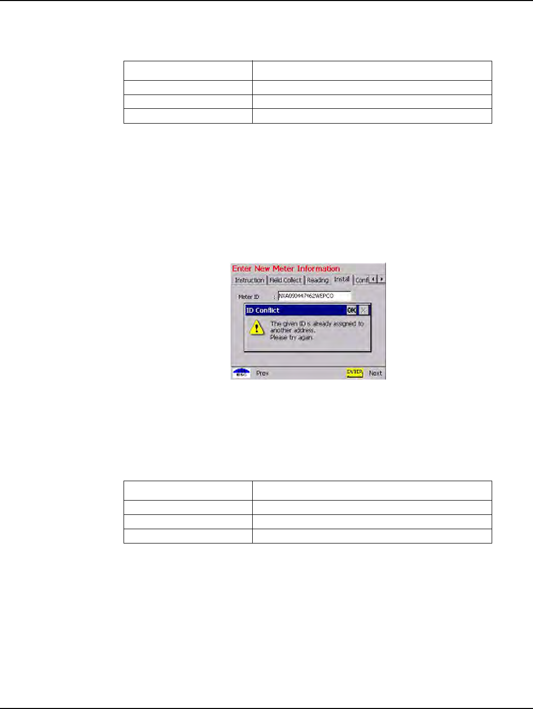
This section covers possible screens generated for invalid meter ID entries.
Figure 3 - 19. Meter already used
The changeout meter ID entered was used on another address.
Change Meter ID
If the existing meter at the account address does not match the utility database, you can enter the
correct meter ID. If so, enter skip code “Meter ID mismatch” and call Supervisor for instructions.
Table 3-11. Handheld Options and Active Keys for Read Out of Range
Option or Active Key Function
MJV båíÉêë=íÜÉ=ãÉíÉê=fa
båíÉê p~îÉë=~åó=ÅÜ~åÖÉë=~åÇ=~Çî~åÅÉë=íç=íÜÉ=åÉñí=ëÅêÉÉå
bp` oÉíìêåë=íç=ãÉíÉê=êÉ~Ç=ëÅêÉÉå
Table 3-12. Handheld Options and Active Keys for Meter Already Used
Option or Active Key Function
lh oÉíìêåë=íç=ëÅ~å=ëÅêÉÉ
båíÉê p~îÉë=~åó=ÅÜ~åÖÉë=~åÇ=~Çî~åÅÉë=íç=íÜÉ=åÉñí=ëÅêÉÉå
bp` oÉíìêåë=íç=ëÅ~å=ëÅêÉÉå
Chapter 3 - Using the HandHeld Device Landis+Gyr
30 98-3107 Rev AA One-way Gas Module Installation Guide
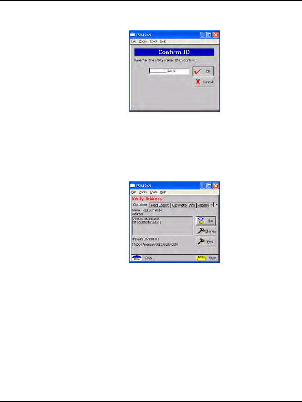
This function updates the HandHeld — even though the existing meter will be replaced with the new
change-out meter.
Figure 3 - 20. Handheld Meter ID Change screen
Skips
In some situations, you cannot install a gas module or replace the existing meter. You must skip it;
for example, the meter is located in the house or an enclosed area and requires you to make
arrangements with the customer for access.
Figure 3 - 21. Options on address screen
1SelecttheSkipoptionintheaddressscreenandpressEnterorS.TheSkipscreendisplays.
Landis+Gyr Chapter 3 - Using the HandHeld Device
One-way Gas Module Installation Guide 98-3107 Rev AA 31
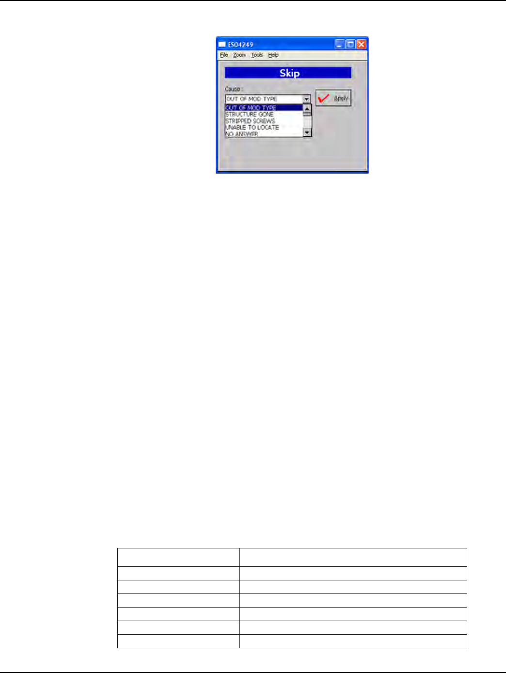
Figure 3 - 22. Handheld Skip screen
Choices on the Skip screen include:
• No access
• Key needed
• Locking ring
• Unsafe condition exists
•Medical
•Dog
• Appointment needed
•No Meter
• Meter Damaged
•Red/Yellow Tag
•Diversion
• Violence code
• Buried meter
• Tilted meter
• Found meter
• Disconnected or Shutoff meter
• Obstacle/Blocked
Table 3-1. Handheld Options and Active Keys for Skips
Option or Active Key Function
vÉë ^ÅÅÉéíë=éêçÄäÉãë=Çáëéä~óÉÇ=~åÇ=êÉíìêåë=íç=~ÇÇêÉëë=ëÅêÉÉå
kç=^ÅÅÉëë fë=íÜÉ=Ñáêëí=çÑ=~=äáëí=çÑ=ëâáé=ÅÜçáÅÉë=Çáëéä~óÉÇ=áå=íÜáë=ÑáÉäÇ
`çããÉåí ^ääçïë=íÜÉ=áåëí~ääÉê=íç=ÉåíÉê=ÅçããÉåíë
båíÉê pÉäÉÅíë=çéíáçåë=kç=^ÅÅÉëëI=vÉëI=kçI=`çããÉåí
^êêçï=`ìêëçê=m~Ç pÅêçääë=íÜêçìÖÜ=ëâáé=ÑáÉäÇë
bp` oÉíìêåë=íç=~ÇÇêÉëë=ëÅêÉÉå
Chapter 3 - Using the HandHeld Device Landis+Gyr
32 98-3107 Rev AA One-way Gas Module Installation Guide
4SelectreasonforskippingmeterandpressENTER.
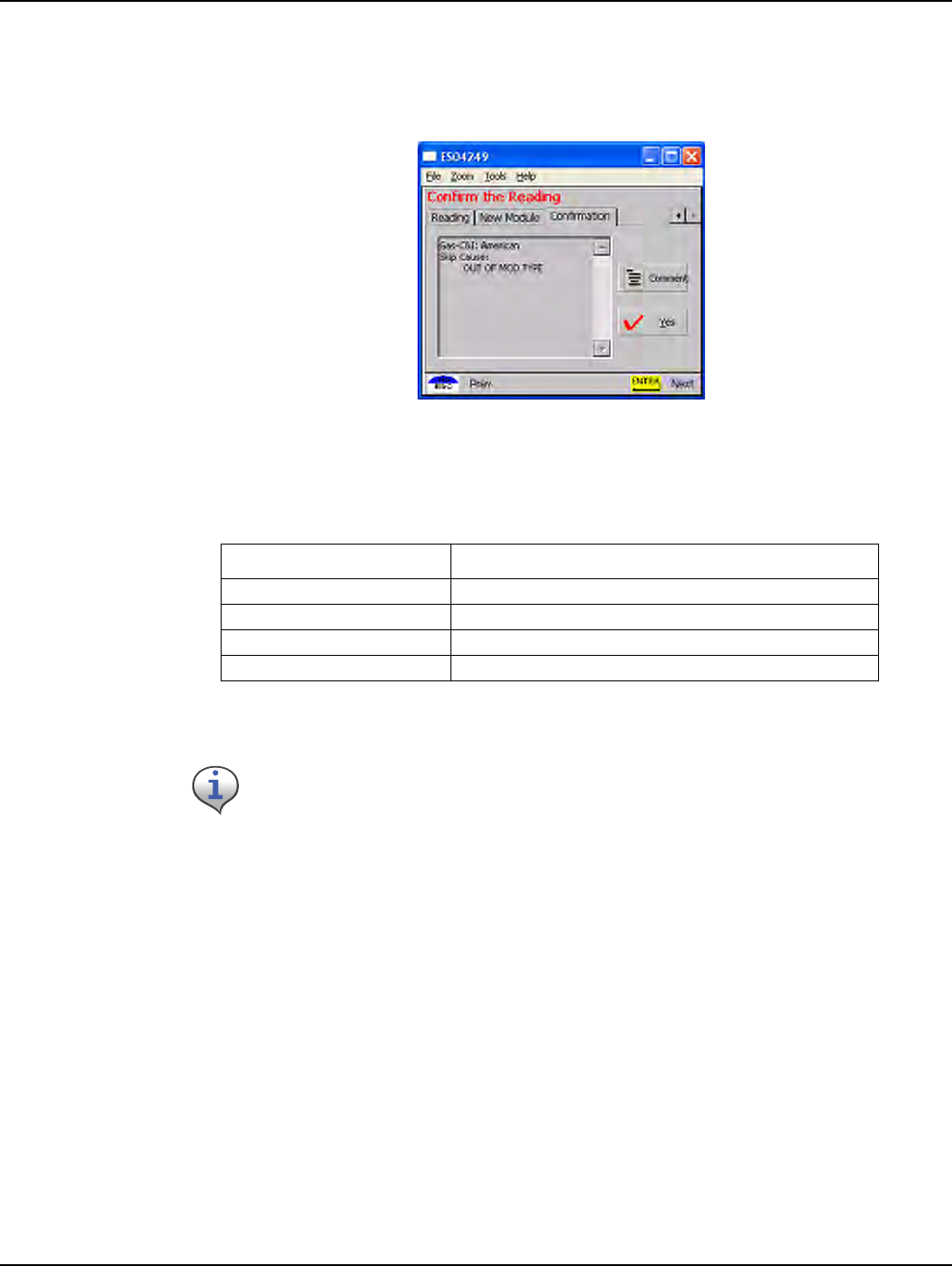
5SelectOktoacceptreasonforskippingmeterID.Ifyouwanttoaddacomment,selectthe
Commentoption.Thesoftwaredisplaystheselectedskipcauseandrequestsconfirmationto
skipmeterinstallation.
Figure 3 - 23. Handheld Skip Confirmation screen
4SelectYestoskipmeterID.Thesoftwarerecordstheskipintheroutestatusandproceedstothe
nextaddress.
Other Features
The following functions are not directly related to the installation process, but are important features
of the Handheld PC.
Table 3-14. Handheld Options and Active Keys for Skip Confirmation
Option or Active Key Function
vÉë ^ÅÅÉéíë=ëâáé=Å~ìëÉ=~åÇ=Çáëéä~óë=íÜÉ=åÉñí=~ÇÇêÉëë=ëÅêÉÉå
kç= oÉàÉÅíë=íÜÉ=ëâáé=Å~ìëÉ=~åÇ=êÉíìêåë=íç=íÜÉ=ÅìêêÉåí=~ÇÇêÉëë
^êêçï=`ìêëçê=m~Ç eáÖÜäáÖÜíë=vÉëLkç
bp` oÉíìêåë=íç=ÅìêêÉåí=~ÇÇêÉëë=ëÅêÉÉå
Medical alert is not normally used on gas meters (medical alert tags are commonly found
on an electric meter).
Landis+Gyr Chapter 3 - Using the HandHeld Device
One-way Gas Module Installation Guide 98-3107 Rev AA 33
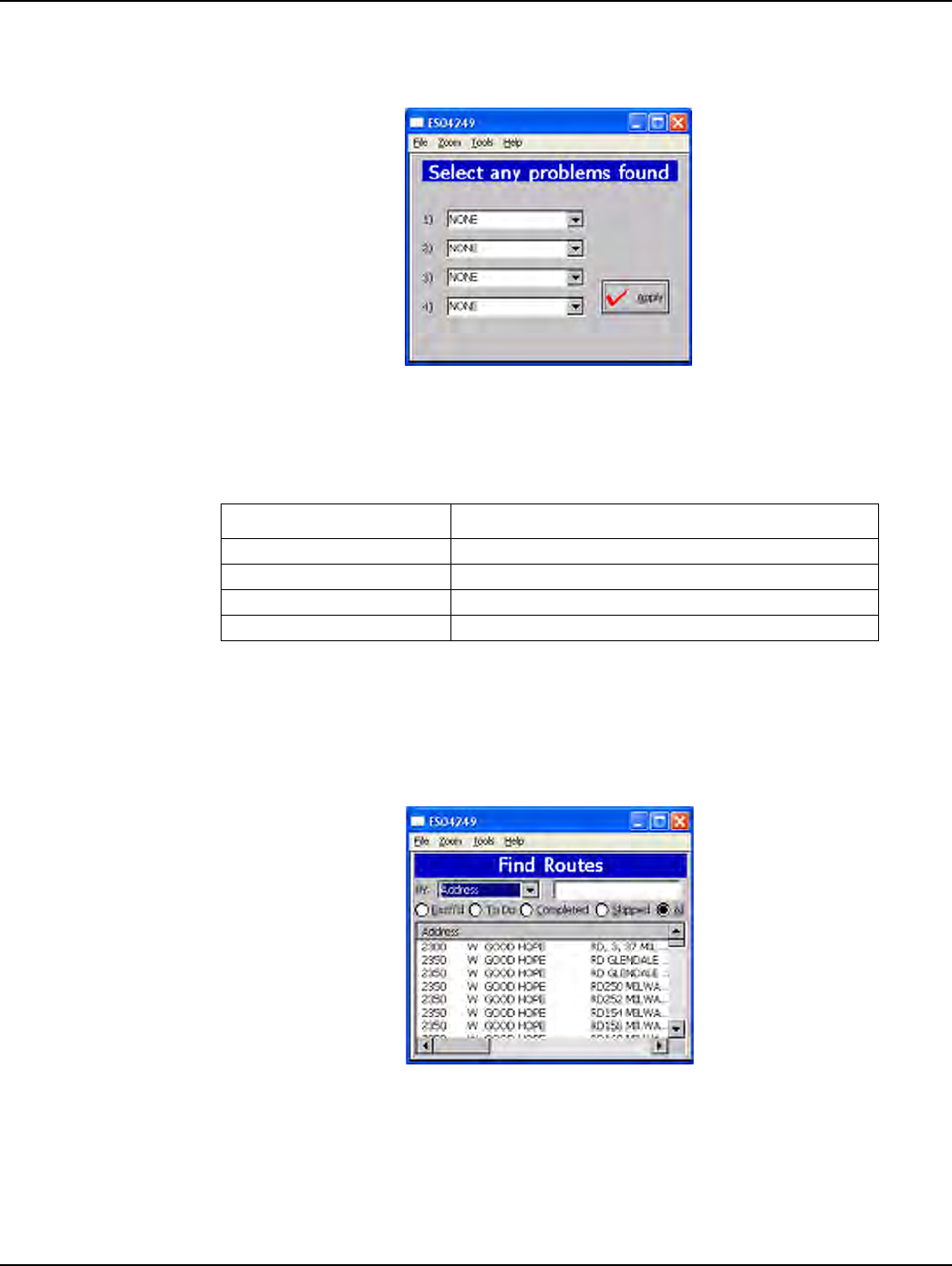
Problems
You can indicate up to four problems to record in a route’s record.
Figure 3 - 24. Problem Indication screen
Find
Use the Find feature to look up addresses, meter data, and route statistics.
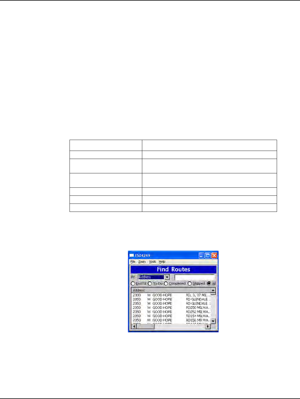
1SelectFindfromtheCustomerAddressscreen.
Figure 3 - 25. Handheld Find Screen
Meter data options include:
• Work Order
• MeterID
Table 3-15. Handheld Options and Active Keys for Route Status
Option or Active Key Function
mêçÄäÉã=ÇêçéÇçïå=äáëí aáëéä~óë=éêçÄäÉã=çéíáçåë
^êêçï=`ìêëçê=m~Ç eáÖÜäáÖÜíë=vÉëLkç
båíÉê p~îÉë=~åó=ÅÜ~åÖÉë=~åÇ=~Çî~åÅÉë=íç=íÜÉ=åÉñí=ëÅêÉÉå
bp` oÉíìêåë=íç=éêÉîáçìë=ëÅêÉÉå
Chapter 3 - Using the HandHeld Device Landis+Gyr
34 98-3107 Rev AA One-way Gas Module Installation Guide
•Address
•Customer Name
• LAN Address
Route Status Options include:
• Exchanged
•All
•ToDo
• Completed
•Skipped
Select search criteria. Two search criteria must be selected: meter data and route status. For example,
use the Arrow Cursor Pad to select Address (meter data) and Completed (route status) to search all
addresses that have been completed.
Figure 3 - 26. Handheld Sample search list
The screen shows all records containing the characters entered in the Find field.
• Alphanumeric keys are active in the Find field.
• Horizontal scroll bar is enabled if the text extends beyond the screen, as in this example.
Table 3-16. Handheld Options and Active Keys for Find
Option or Active Key Function
pÉ~êÅÜ=Äó aáëéä~óë=ãÉíÉê=Ç~í~=ëÉ~êÅÜ=çéíáçåë
qÉñí=ÑáÉäÇ båíÉê=Ñìää=çê=é~êíá~ä=~ÇÇêÉëë=áåÑçêã~íáçå=íç=êÉÇìÅÉ=íÜÉ=äáëí=
êÉíìêåÉÇ
o~Çáç=Äìííçåë vçì=Å~å=å~êêçï=óçìê=ëÉ~êÅÜ=íç=êÉíìêå=çåäó=bñÅÜ~åÖÉÇI=qç=
açI=`çãéäÉíÉÇI=pâáééÉÇI=çê=^ää=êçìíÉë
båíÉê pÉäÉÅíë=ÜáÖÜäáÖÜíÉÇ=çéíáçå
^êêçï=`ìêëçê=m~Ç pÅêçääë=íÜêçìÖÜ=ëÉ~êÅÜ=ÑáÉäÇë=~åÇ=ÜáÖÜäáÖÜíë=çéíáçåë
bp` oÉíìêåë=íç=ÑìåÅíáçå=ëÅêÉÉå
Landis+Gyr Chapter 3 - Using the HandHeld Device
One-way Gas Module Installation Guide 98-3107 Rev AA 35
• Arrow keys move the cursor from the Find field to the data records.
• Space (SP) key moves from addresses to Find field.
4SelectOkorOtoacceptsearchcriteriaanddisplaysearchrecords.
5GobacktotheSearchlist,andtypeElmtosearchalladdresseswith“Elm”intherecord.Then
selecttherelevantonebyusingthespaceSPkeytomovefromaddressestoFindfield.
6UsetheArrowCursorPadtomovethecursortothedatarecordsanduseENTERtoselectthe
desiredrecord.
From this screen, additional information may display or you can modify the data record (for
example, reinstall meter, record problem conditions, or change status to skip meter).
Table 3-17. Handheld Options and Active Keys for sample search list
Option or Active Key Function
^JwI=MJV båíÉê=ëÉ~êÅÜ=íÉñí=áåíç=íÜÉ=cáåÇ=ÑáÉäÇ
^êêçï=`ìêëçê=m~Ç pÅêçääë=íÜêçìÖÜ=ëÉ~êÅÜ=ÑáÉäÇë=~åÇ=ÜáÖÜäáÖÜíë=çéíáçå=^ÇÇêÉëëI=
qçaçI=lâ
båíÉê p~îÉë=~åó=ÅÜ~åÖÉë=~åÇ=~Çî~åÅÉë=íç=íÜÉ=åÉñí=ëÅêÉÉå
bp` oÉíìêåë=íç=ÑìåÅíáçå=ëÅêÉÉå
Table 3-18. Handheld Options and Active Keys for sample search record
Option or Active Key Function
_~Åâ oÉíìêåë=íç=cáåÇ=ëÅêÉÉå
båíÉê p~îÉë=~åó=ÅÜ~åÖÉë=~åÇ=~Çî~åÅÉë=íç=íÜÉ=åÉñí=ëÅêÉÉå
^êêçï=`ìêëçê=m~Ç eáÖÜäáÖÜíë=çéíáçåë=Ä~Åâ=çê=fåëí~ää
Notes:
36 One-way Gas Module Installation Guide
Using the HandHeld Device

4
One-way Gas Module Installation Guide 98-3107 Rev AA 37
On-Site Preparation
Arrival at Install Site
1Uponarrivingattheinstallationsite,verifytheaddressintheHandheld.ChecktheHandheld
forspecialinstructionsforthatsite(forexample,medicalcustomer,dog,keyrequiredforaccess
tometer,meterlocation,andsoon).IfamedicalalertcodeappearsintheHandheldforthat
addresstheyaretoskiptheinstallenteranappropriateskipcodeandmovetothenext
exchange.Amedicalalerttagmaybelocatedontheelectricmeter.
2IftheinstallercomesacrossameterwhereamedicalalertcodeappearsintheHandheldforthat
address,theyaretodiscontinuetheexchange,entertheappropriateskipcode,andmovetothe
nextexchange.
3VerifythatthemeterIDofthemeterattheaddressisthesameasthatintheHandheldrecord;if
not,verifyitasecondtime.IfthemeterIDdoesnotmatch,recordtheinformationtoinclude
mismatchedIDonhardcopy,recordskipcodeofmeterIDmismatchandcallyourSupervisor
fordirection.
4Checktoverifythatthesealsareintactandpresent.Ifthemeterisunsealedandthereisno
evidenceoftamperingcompletethemeterexchangeormoduleretrofit.Ifthereissuspected
tamperingorevidenceofdiversiondonotcompletetheinstall,recorddiversiononhardcopy
andenterskipcodeofdiversioninHandheldandcallyoursupervisorimmediately.
5Ifthepremiseisvacantandtheserviceisshutoffattheserviceriservalve,completethemeter
exchangeifatallpossible.Ifyouareunabletogainaccesstothepremisefinishyourroute,then
tryagainbeforereturningtotheCrossDock.EnterappropriatecodeinHandheld.
6Inspectthemeterforanygasleaks,unsafeconditions,excessiverustingordamage.While
performingthistechnicalreviewlookoverthemeterforpoorconditionssuchasexcessrust,
tampering,orodorofgas.Ifyoujudgethemeterisseriouslydamaged,reportit,enterthe
appropriatecodeintheHandheld,andcallyoursupervisorfordirections.
7Ifitisdeterminedthatthemeterhasnounsafeconditions,youarereadytoproceedwiththe
moduleretrofit.DatawillberequiredtobeenteredintotheHandheld.Ifthereadingisoutof
range(indicatedbyapromptontheHandheld),thenretypethemeteridentificationnumberʹs
lastfourdigitstore‐verifythecorrectmeter.Reenterthegasmeterindexreadintothe
Handheld.
SeeʺToBeginMeterModuleRetrofitʺonpage 43forinformationaboutmoduleexchange
instructions.
8Ifthemeteristobeexchangedanditispartiallyburied,enteraskipcodeof“buried”andmove
tothenextaccount.Ifatiltedmeteristobeexchanged,performtheexchangeandcorrectthe
tilt.Ifamoduleistobeinstalledonatiltedmeter,completetheinstall,andenteraskipcodeof
“tilted.”
9Iftheinstallerismetbyaviolentorthreateningcustomer,immediatelyleavethepremiseand
callyourSupervisor.Ifnecessary,dial911,afterwhichyouwillenterintotheHandheldandon
thehardcopyaskipcodeof“violencecode.”
Notes:
38 One-way Gas Module Installation Guide
On-Site Preparation

5
One-way Gas Module Installation Guide 98-3107 Rev AA 39
Gas Meter Exchange
Meter Exchange Process
Arriving at the Location
1Theinstallerconfirmsthattheyareattherightrouteaddressforthatappointmentusingthe
Handheld.Theinstallerarrivesatthelocationon‐timeandwithallthetoolsandequipment
necessarytocompletetheinstallationwithouthavingtoreturntothesupportvehicle.If
applicable,locatetheoutsideshutoffvalveincaseoftroubleoremergency.
2Whenthecustomeranswersthedoor,introduceyourselfandstatethereasonforyourvisit.
–verifythatthecustomerisatleasteighteenyearsofage.
– Showthecustomeryouridentification.
3Confirmthenatureoftheappointmentandthetimecommitmentrequiredfromthecustomer.
Makesurethecustomerknowsandagreesthatitisconvenientforyoutoturnoffthegasduring
theinstallationprocess.
Verifying the Meter Site
Locate the meter and confirm the existing meter number, type, and size.
–Ifthemeternumberiscorrectbuttypeandsizedonotmatchtheequipmentthatyouhave
beenissued,callyourSupervisorandrequesttheappropriateequipment.
–IfthemeterIDdoesnotmatchtheinformationinthehandheld,callyourSupervisorfor
meternumberverification.
–Ifallinformationiscorrect,continuetheinstallationprocess.
–Priortoproceedingwiththemeterexchangeprocess,inspecttheconditionofthegas
regulator.Iftheregulatorisdefective,itmustbereplaced.Followtheutility‐specific
guidelinesforregulatorexchange.

Chapter 5 - Gas Meter Exchange Landis+Gyr
40 98-3107 Rev AA One-way Gas Module Installation Guide
Confirming Proper Installation Conditions
1Fortheinstallationtoqualify,confirmALLofthefollowingpre‐existingconditions:
–Visuallyexaminetheshut‐offthatitdoesNOTshowsignsofleakingordisrepair.
–PerformthesnifftestforsignsofgasleaksusingtheNaturalGasDetectionDevice,andthen
thesoaptestontheshutoffandcouplings.
–NoDiversionorTamperingEvident‐Visuallyinspecttheservicetothemeterforsignsof
diversionortampering.
– AppropriateAccess‐Confirmthataccesstothemeterallowsaminimumacceptablework
areatobeestablished.Minimumworkareaincludeswrenchclearance,accesstoshut‐off.
– AppropriateService&PipingCondition‐Visuallyinspecttheageandconditionofthe
serviceandpiping.Confirmthatserviceandpipingarefitfortheremovalandinstallation
ofanewmeterandthattherearenopre‐existingleaks.
– AppropriateMeterOrientation‐Confirmthatthemeterisinstalledhorizontallyorsuch
thatthemeterexchangecannottakeplace.
–IfanyimproperconditionsarefoundcontactyourSupervisorimmediately.TheSupervisor
willconfirmyourassessmentandgiveyoudirectionforeithercompletingtheinstallationor
issuingaskipcodeintheHandHeld.
2Setuptheareaforinstallation.Forinsidesets,turnallavailablelightingon.Clearan
appropriateworkspaceandlayoutalltools,equipment.Prepareforleaksoremergencyshut‐
off.
Shutting Off the Service
1Notifythecustomerthatgasservicewillbeinterrupted(reconfirmallgasapparatusesareoff).
Inspectfortheproperoperationofeachgasappliance.Inspectthemetersetforcorrosion,burial
oroverbuilding,damage,improperinstallation,misalignment,outdatedregulator(Model
1213Bor043R),orthesmellofnaturalgas.
2 Connectthebondingjumperfromservicerisertothepremiseline.Verifythattheexistingmeter
isoffbyisolating(shutoff)allgasapparatusesandconfirmthatthereisnoflowonthemeter
andregister.Ifthemeterisnotfunctioningcorrectly,contacttheSupervisorimmediately.The
Supervisorwillconfirmyourassessmentandgiveyoudirection.
3 Manuallyclosethecustomerʹsshutoffvalve.
–Ifyouhaveanyproblemclosingthevalve,contactyourSupervisorfordirectionwhichmay
include,ifapplicable,usingtheoutsidecurbstopforshut‐off.
–Iftheoutsidecurbstopisactivated,theSupervisorwillnotifytheUtilitySupervisor.
4Removetheoriginalmeter.
aUsingapipewrenchandbackup,attempttoloosenthemetercouplingnuts.
bUsemildtorquebuildingtomoderatesteadytorqueuntilthecouplingnutbeginstoturn.
cDonotjerkorsnapthewrenches.Damagecouldoccur.
dLoosenbothcouplingnutsandremovetheoldmeterfromthemeterset.
Ifyouhaveanyproblemlooseningthecouplingnuts,contactyoursupervisorfordirection.
eWhenapplicable,removealloldgasketmaterialinthecouplingnuts.Inspecttheregulator
andexchangeifitisdamagedordefective.

Landis+Gyr Chapter 5 - Gas Meter Exchange
One-way Gas Module Installation Guide 98-3107 Rev AA 41
Installing the New Meter
1Removethenewmetertagfromthenewmeter.
2Writeinstalldate,address,andinitialsonnewmetertag.
3Placenewmetertagontheoldmeterregister.
4Insertnewgasketswhereapplicable.
5 Exchangetheregulatorifdamagedoroutdated,andexchangeanydamageinsulatingunions.
Levelthemetersetifthesetistilted.
6 Tightentheinlet‐couplingnut.
7Installpressuregaugetometeroutlet,slowlyopentherisevalve,andadjustregulatorto
appropriategaspressureatthemeteroutlet.
aClosetheriservalveandremovegauge.
bVerifymeteroperation.
c Reconnecttheoutletpiping.
8Beforere‐servicing‐ifservicewasshutoffpriortothemeterexchange,donotrestoreservice.
Restoring Service, Purging the Air, and Performing the Leak Test.
1Opentheshut‐offvalveveryslowly.
–IfyouhaveanyproblemopeningthevalvecontactyourSupervisorfordirection.
2Checkthetestdialformovementtomakecertainnoleaksoccurredwhileperformingthe
installation.
aSealtheregulator.
bDisconnectthebondingjumper.
cCleanandpaintthemeterset.
3Checkthecouplingnuts,serviceandpipingforleaksperform“leaktest”(snifftestforsignsof
gasleaksusingtheNaturalGasDetectionDevice,andthesoaptest)andre‐tightenifnecessary.
4 Reenterthepropertyandpurgetheairfromthegaslinebybleedingthefurthestgasapparatus
fromthemeter.Youmustbleedeachindividualapparatus.
Relighting All Apparatuses and Confirming Their Operation
Follow the procedure provided to you by the Utility for appliance relighting. If any adverse
conditions arise, immediately shut off the gas, contact your supervisor for instructions, and record
the appropriate comment in the Handheld such as, red/yellow tag defective appliance situation. Enter
a Skip code such as, “red/yellow tag” in the Handheld.
During the installation, replace all biscuits in the outlet piping, and leave meter off “as
found”.

Chapter 5 - Gas Meter Exchange Landis+Gyr
42 98-3107 Rev AA One-way Gas Module Installation Guide
Programming the Module
Refer to Chapter 3, Using the HandHeld Device.
Performing Data Collection
1SeeChapter 3,UsingtheHandHeldDevice.
2Sealthenewmeter.
Cleaning Up the Work Area
Clean up all installation tools, equipment and debris. Turn off any lights that you may have turned
on. Restore the customer premise to the pre-visit condition.
Exiting the Premise
1Doalastchecktoensurethatyouhaveallofyourequipmentandtools.
2 Thankthecustomerforallowingustoservicetheirgasmeter,exitthepremise,andprovidethe
customerwithadoorhanger.
Module Retrofit (Index or Register) Replacement
Refer to Chapter 6, Meter Module Retrofit.
Customer Skip or Cancellation
If the customer's existing conditions do not qualify for new meter installation notify your Supervisor.
Wait at the site until your Supervisor arrives for further instructions. If, in the Supervisor's opinion,
the condition of the customer's existing service piping or appliances is such that significant damage
would result from attempting to remove and replace the existing gas meter, your Supervisor will so
inform the Utility of the condition. The Supervisor will advise you to:
• Inform the customer as to why the change-out will not take place.
• Document situation in handheld.
• Direct you to your next appointment.
If There Is Damage On Site When You Arrive
• Call your Supervisor immediately. Communicate the gravity of the situation. Your Supervisor
will immediately initiate any necessary actions.
• Do not leave the customer site until directed to do so.
• It may be necessary to dial 911.
IMMEDIATELY turn off the gas. This will eliminate or minimize any property damage
to customer.

Landis+Gyr Chapter 5 - Gas Meter Exchange
One-way Gas Module Installation Guide 98-3107 Rev AA 43
Battery Change Out
When the NOC analyst notices that the battery flag (R) is set, it could be due to:
• a single end-point occurrence, where the end-point may require more current to operate. In this
case, a single battery needs to be replaced
• occurrence on several end-points, where a battery change out program needs to be implemented
within the following year
• the flag being set during the coldest part of the day, where the battery may have less than 20% of
energy left (2-4 years of service time)
• occurrence more often even during the daylight hours. In this case, the battery has even less
energy remaining (1-2 years of service time)
To Change Out The Battery
1Swipeamagnetonthelefthandsideofthemainboardcompartment
2ListenforuptotenbeepsontheRFbuster(whichensuresthatthelatestdataissavedtonon‐
volatilememory)
3Removethefourmetermountingscrews
4RemovetheGasLXmodulefromthegasmeter
5Openthebatterycompartmentdoor
6Replacethebatteryassemblywithanewone(40‐1590H)
7Closethebatterydoor
8Replacethemoduleontothegasmeterusingthefouroriginalmountingscrews
9Inserttwonewsecuritysealsintothehousing.
. .
If the gasket is old and no longer provides a good meter to module seal, replace the meter
gasket with a new one.
If the module has already gone stale, perform the above steps, with the exception that
when the battery door is open, connect the USB programming cable to Gas LX module. Use
the HH to re-enter the energy value from the mechanical index dials and re-program the
module.
Once the above steps are completed, wait for at least three hours for all flags to be cleared
(based on five transmissions per hour and Alarm Count = 10).
Notes:
44 One-way Gas Module Installation Guide
Gas Meter Exchange
6
One-way Gas Module Installation Guide 98-3107 Rev AA 45
Meter Module Retrofit
This chapter outlines the procedure for Meter Module installation. There are many meter module
types supported. Two examples appear below.
Figure 6 - 1. Two of the many supported Meter Module types
To Begin Meter Module Retrofit
Prior to beginning the meter module retrofit, make sure you have followed the steps in "If the
installer comes across a meter where a medical alert code appears in the Handheld for that address,
they are to discontinue the exchange, enter the appropriate skip code, and move to the next
exchange." on page -37.
1PlugtheprogrammingcablefromtheHandheldintotheprogrammingpowercableonthe
MeterModule.RefertoChapter 3,UsingtheHandHeldDevice.
2ProgramtheMeterModuleandchecktheHandheldforsuccessfulprogramming(example,
Dials=4,MeterID=0123456G,MeterConstant=2).
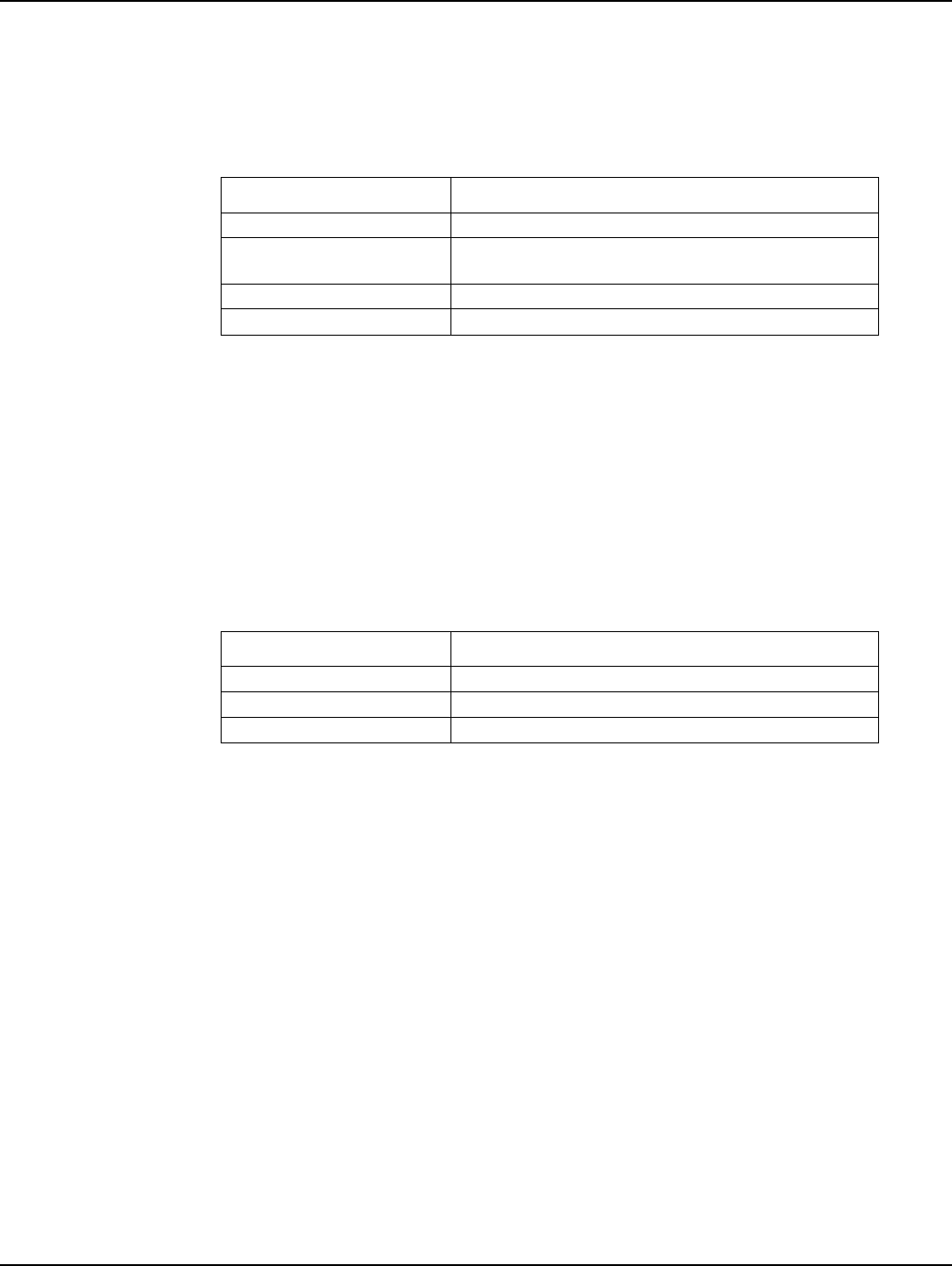
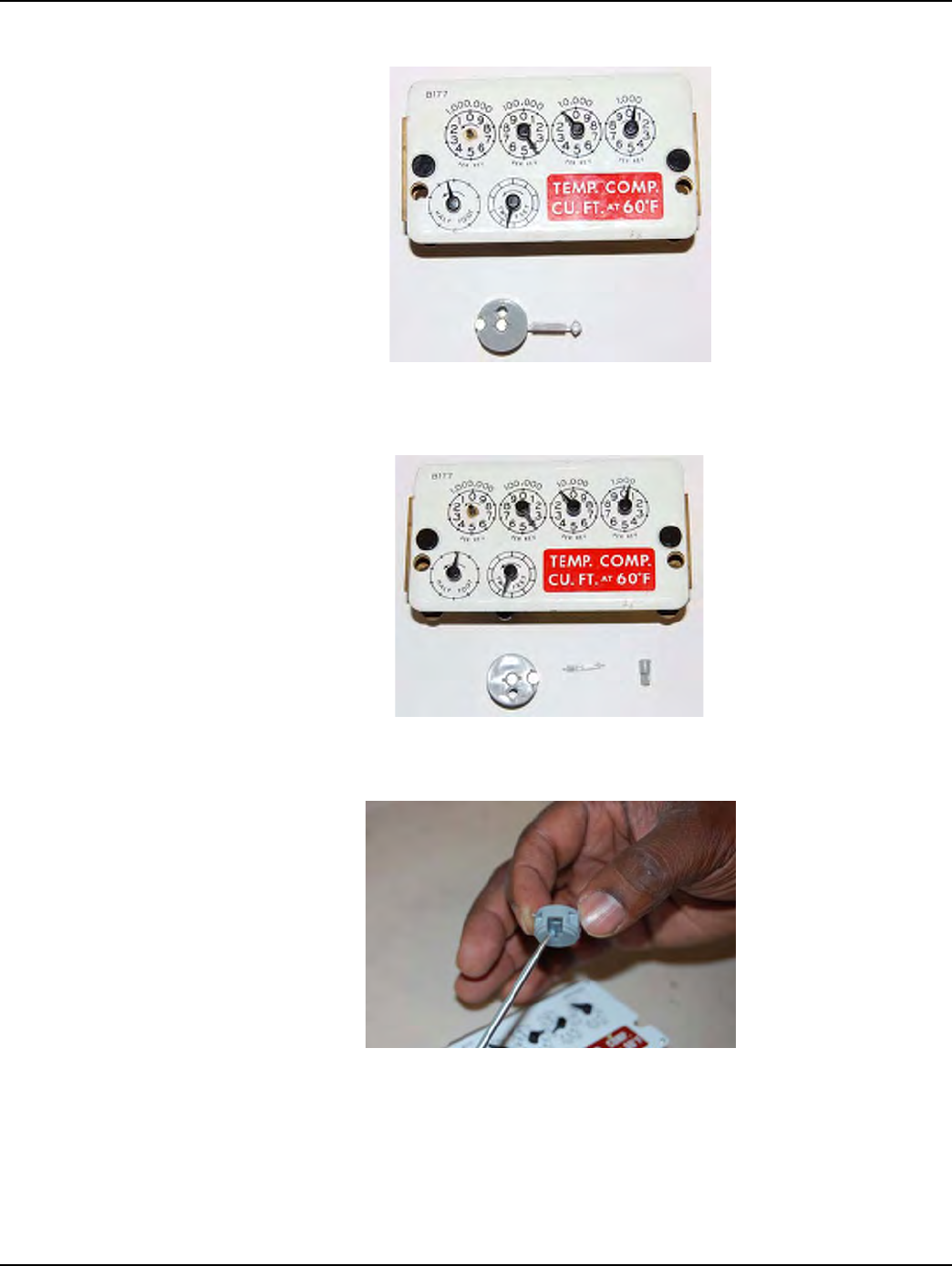
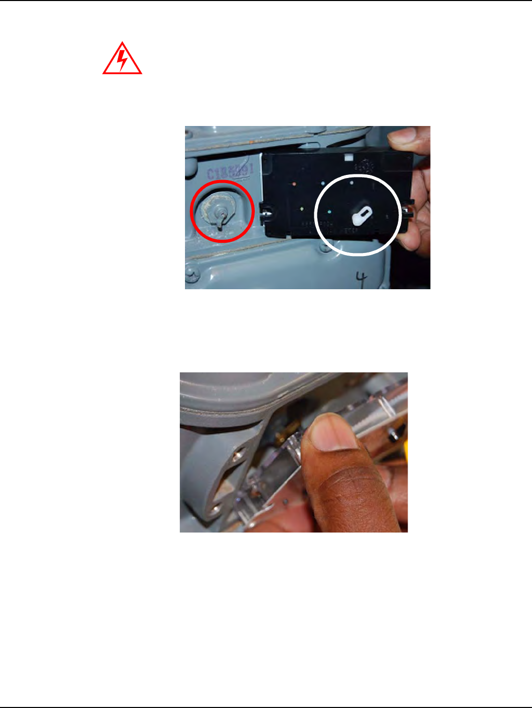
3Removethetampersealsandindexcoverfromtheoriginalgasmeter.
A Count = 2 feet
of 1 X 2 = 2 ft3
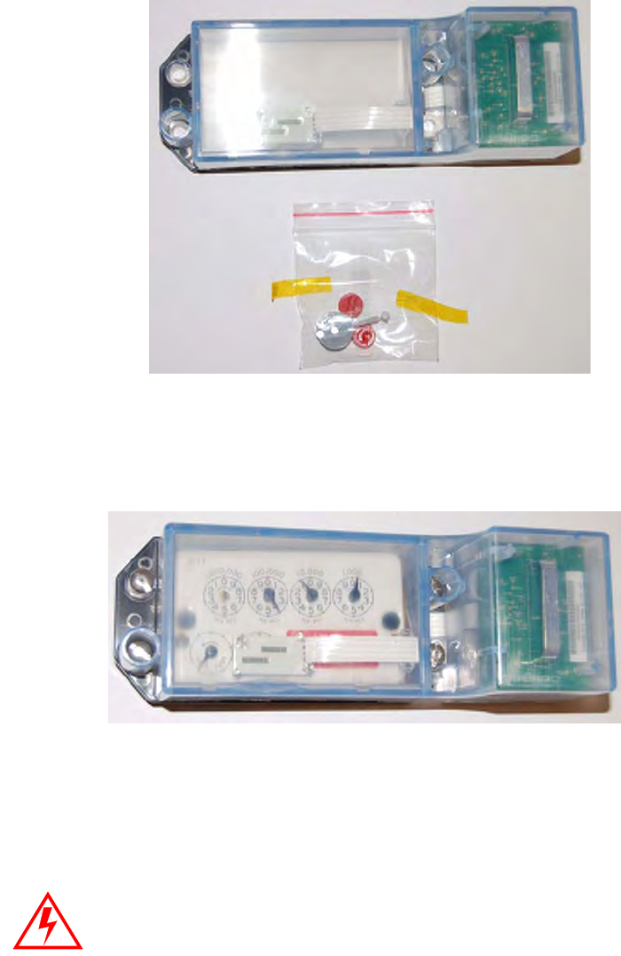
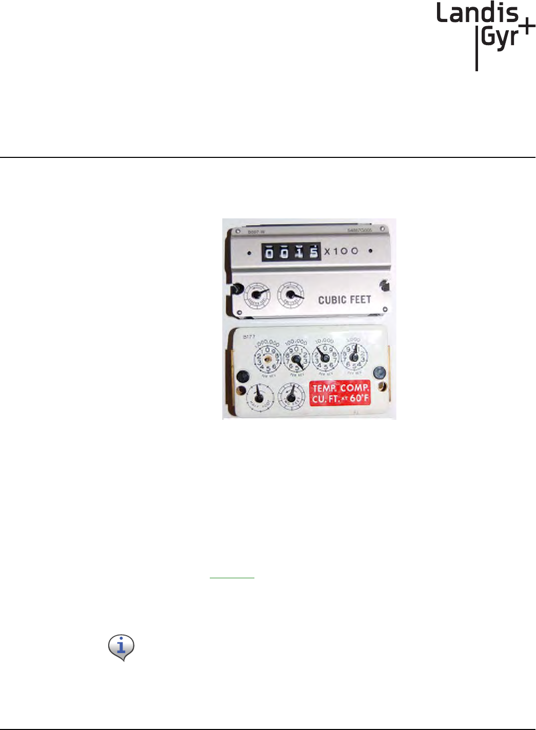
Figure 6 - 2. Meter Module kit before installation
4 Followsteps1‐4inʺToBeginMeterModuleRetrofitʺonpage ‐45.
Figure 6 - 3. Index and Gas LX Index Cover
5Removealloftheoriginalgasketmaterial.Replacetheindexifitisdamagedorifthegearsare
discolored.
Metal indexes cannot be used and must be replaced.
Landis+Gyr Chapter 5 - Meter Module Retrofit
One-way Gas Module Installation Guide 98-3107 Rev AA 47
WHENREPLACINGANINDEX,YOUMUSTENTERTHEMETERREADINTOTHE
HANDHELDANDNOTE“INDEXEXCHANGED”INTHECOMMENTSECTION.ForIndex
visualverificationandexchange,seeAppendix A,SupplementalInformationAboutIndexes.
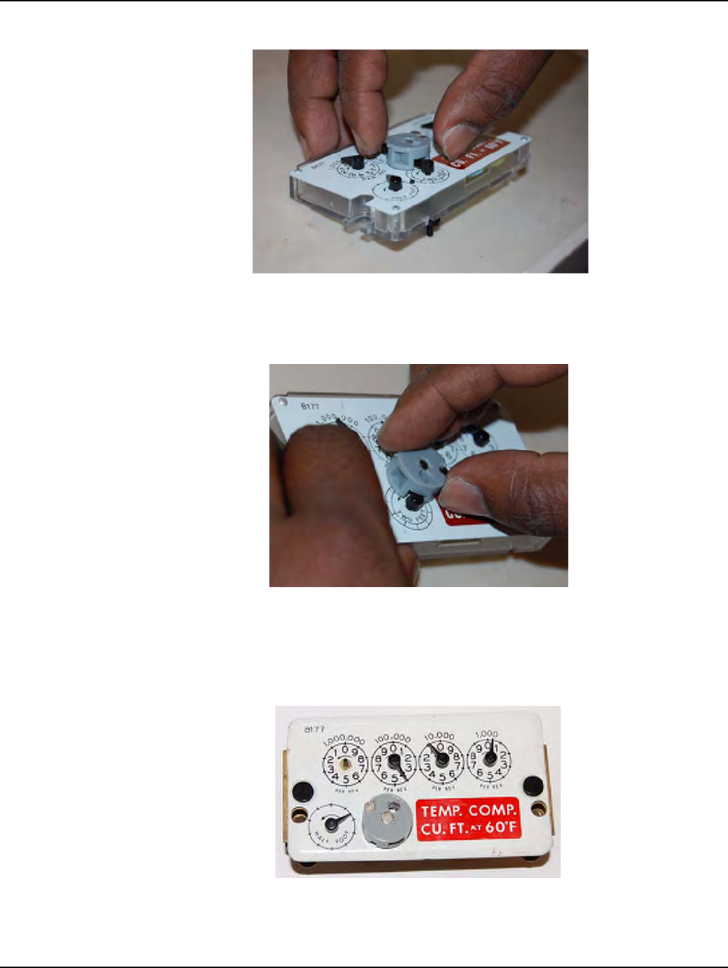
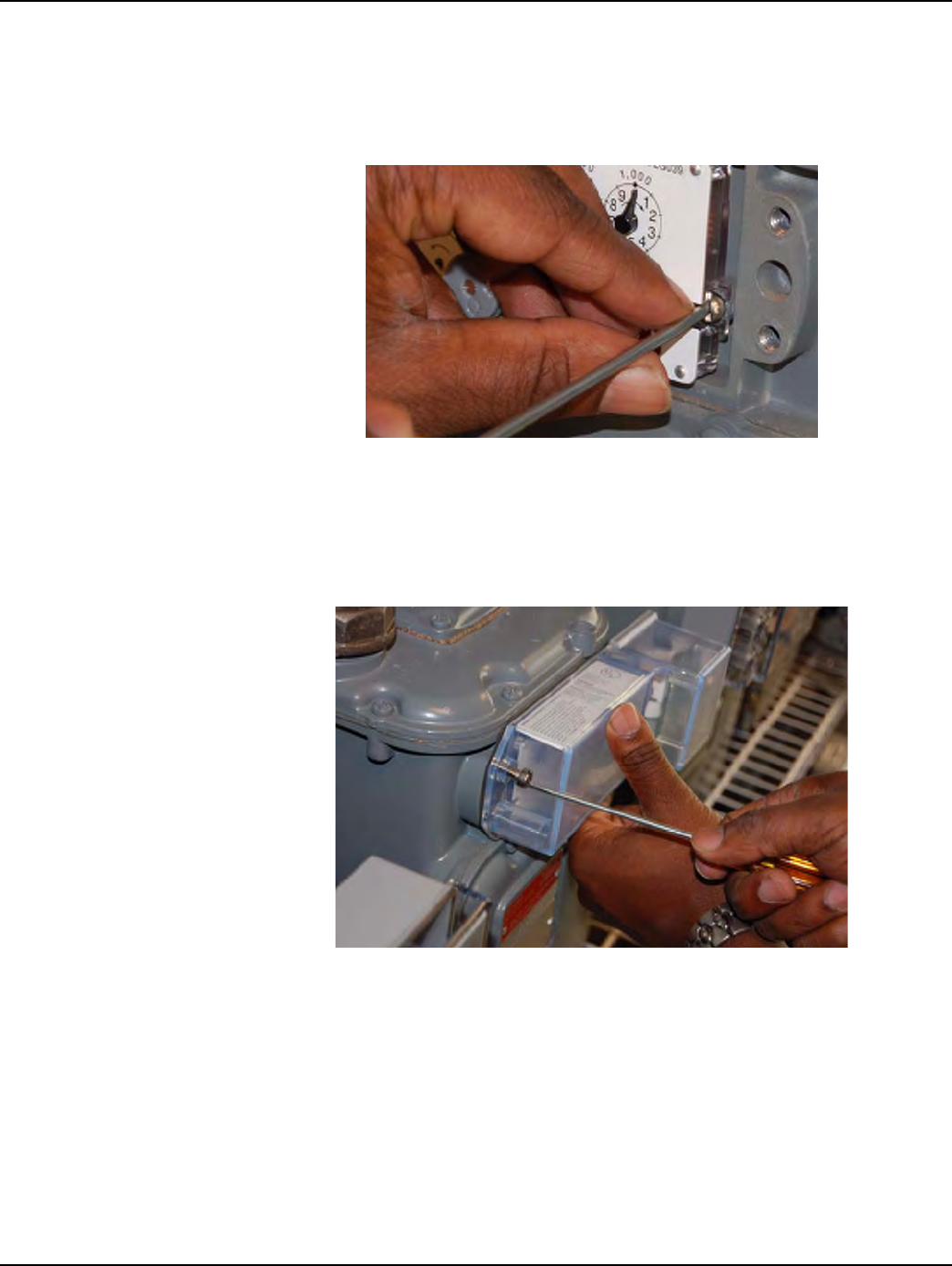
Figure 6 - 4. Removing the Index (one screw on each side)
6Cleantheareabehindtheindexandcovergasketsurfaceonthemeterwithawirebrushand
gasketscraper.
7Makesurethatthelocationofthedialsonthemeterisfreeofanydebristhatmayhamper
moduleinstallation.
8InstalltheMeterModuletothemeterbyscrewinginthefouroriginalmountingscrews.
Tightenthescrewsuntilthecoversitssnug,thentightenandadditionalquarter‐turn.
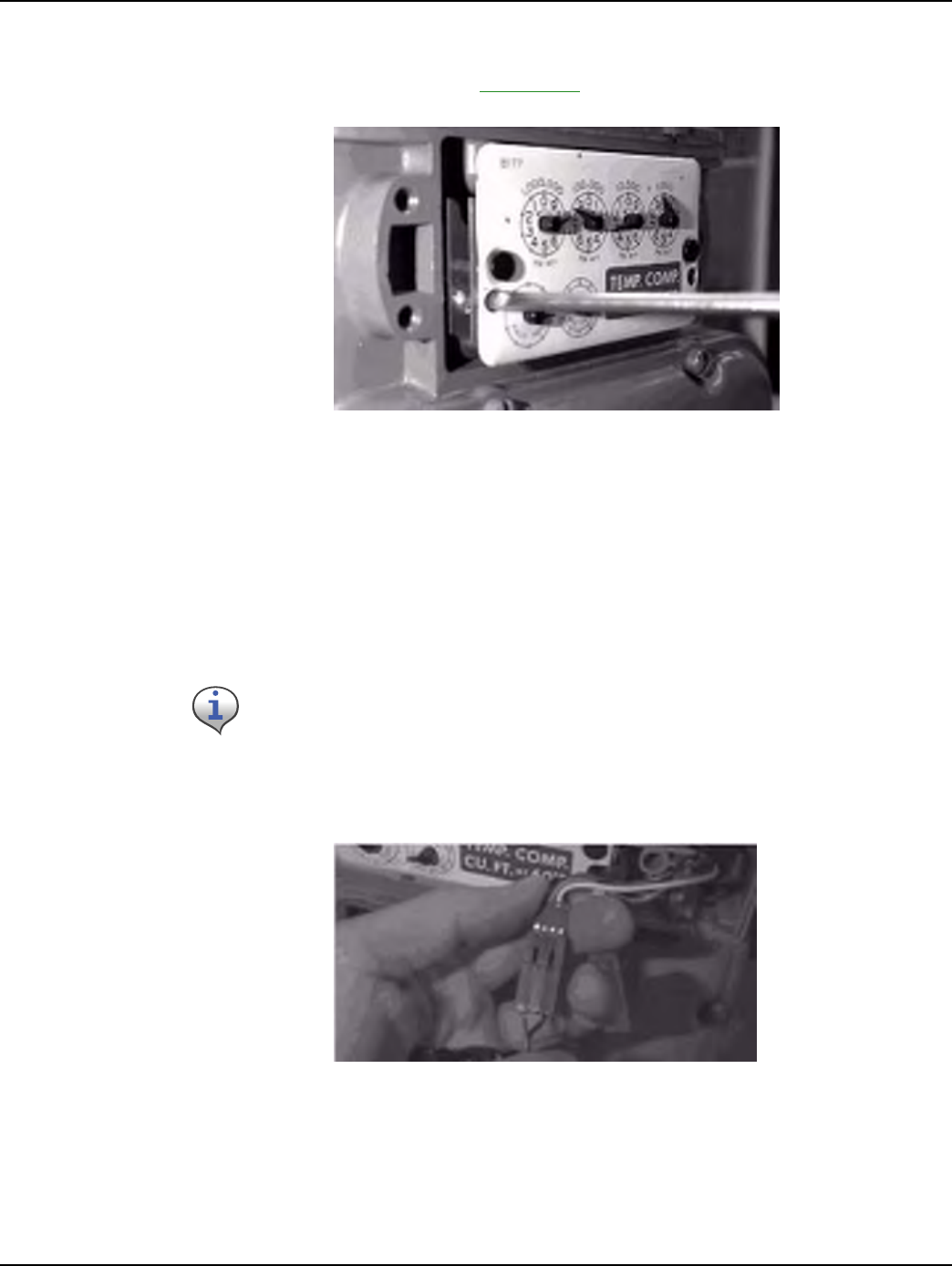
9Plugthebatteryintotheprogrammingportpowercableandplaceitinthebatterycompartment
withthebatterywiresontop.
Figure 6 - 5. Connecting the battery
Use a torque screwdriver set at 10 inch-pounds to install the screws for all module
installations.
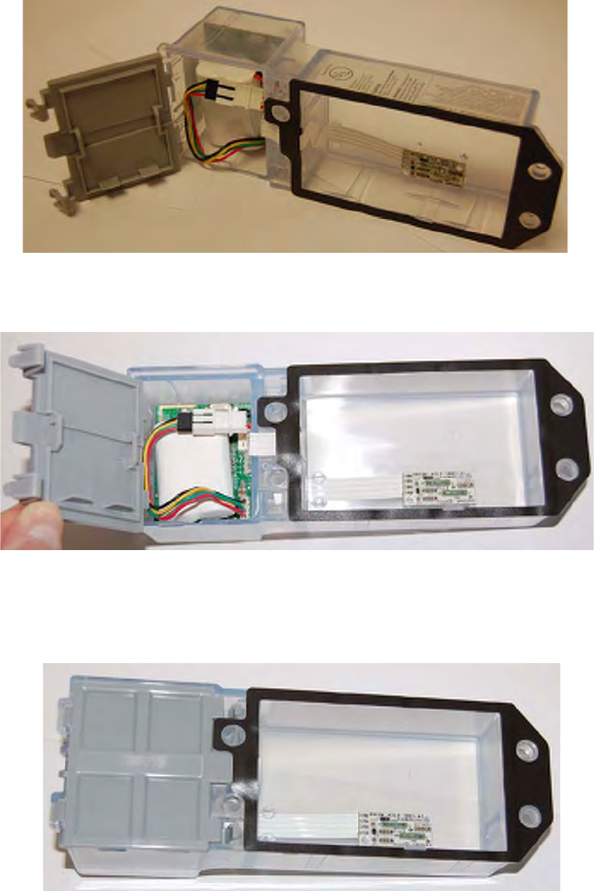
Figure 6 - 6. Installing the battery with the battery cable on top
Figure 6 - 7. Properly installed battery
Figure 6 - 8. Battery Compartment closed
Landis+Gyr Chapter 5 - Meter Module Retrofit
One-way Gas Module Installation Guide 98-3107 Rev AA 49
After the battery is installed, prepare to install the Dial Wheel .
Figure 6 - 9. Dial Wheel Kit
10 Clipthepiecesapart.
Figure 6 - 10. Dial Wheel Kit separated for installation
Figure 6 - 11. Reader Interface Dial Wheel Needle Slot
11 WhileholdingtheDialWheel(DW),notethelocationoftheNeedleSlot.Withtheindexsitting
onaworksurface,settheDWontheindexfacewiththeneedleslotorientedtowardsthe
needle.
Chapter 5 - Meter Module Retrofit Landis+Gyr
50 98-3107 Rev AA One-way Gas Module Installation Guide
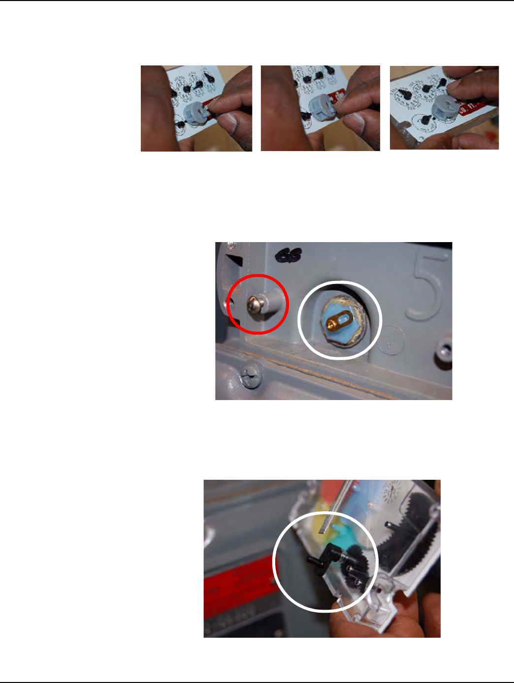
Figure 6 - 12. Dial Wheel with needle slot positioned for unit needle entrance
12 SlidetheDWtowardtheneedle...
Figure 6 - 13. Moving the Dial Wheel onto the index unit pointer
...until the DW center contacts the needle mount. The needle mount center will gently impede the
Dial Wheel.
Figure 6 - 14. Reader Interface Wheel installed
Landis+Gyr Chapter 5 - Meter Module Retrofit
One-way Gas Module Installation Guide 98-3107 Rev AA 51
13 TaketheDWPinandinsertthepinintotheDWhole.Youwillfeelagentlesnapasthe
pinseatsintoplace.
Figure 6 - 15. Installing the Dial Wheel Pin
14 PreparetomounttheDialWheelonthemeterbylocatingthemeterWigglerand
startingabareminimumofthethreadsforoneoftheMeterIndexmountingscrews.
Thefollowingpictureshowsthescrewtotheleftofthewigglerinstalled.
Figure 6 - 16. Meter Index Mounting screw and Meter Wiggler
15 Asyoupreparetomountthemeterindex,notethedrivepinontherearofthemeter
index,anditsposition.
Figure 6 - 17. Meter Index Drive Pin
Chapter 5 - Meter Module Retrofit Landis+Gyr
52 98-3107 Rev AA One-way Gas Module Installation Guide
Figure 6 - 18. “1-foot” Meter Wiggler and “1-foot” Meter Index Drive Pin
16 Whileslidingtheleft‐sideMeterIndexmountingslotundertheMImountingscrew,alignthe
MeterIndexDrivePinwiththeMeterWiggler.
Figure 6 - 19. Aligning the Meter Index Drive Pin and mounting the Meter Index
All photographs and installation steps in this procedure refer to “2-foot” meters.
For a “1-foot” meter installation, the Meter Wiggler and the Meter Index Drive Pin
are of a slightly different configuration, as shown in the following photograph. All
installation steps are identical except for the meter and drive pin configuration.
Landis+Gyr Chapter 5 - Meter Module Retrofit
One-way Gas Module Installation Guide 98-3107 Rev AA 53
17 AfteraligningtheMeterIndexDrivePinwiththeMeterWiggler,movetheMeter
Indexintooperatingposition,holdtheMeterIndexwithonehandandtightenthe
mountingscrewenoughturnstoholdtheMeterIndexinplaceasyouprepareto
installtheotherMeterIndexmountingscrew.
Figure 6 - 20. Installing the remaining Meter Index mounting screw
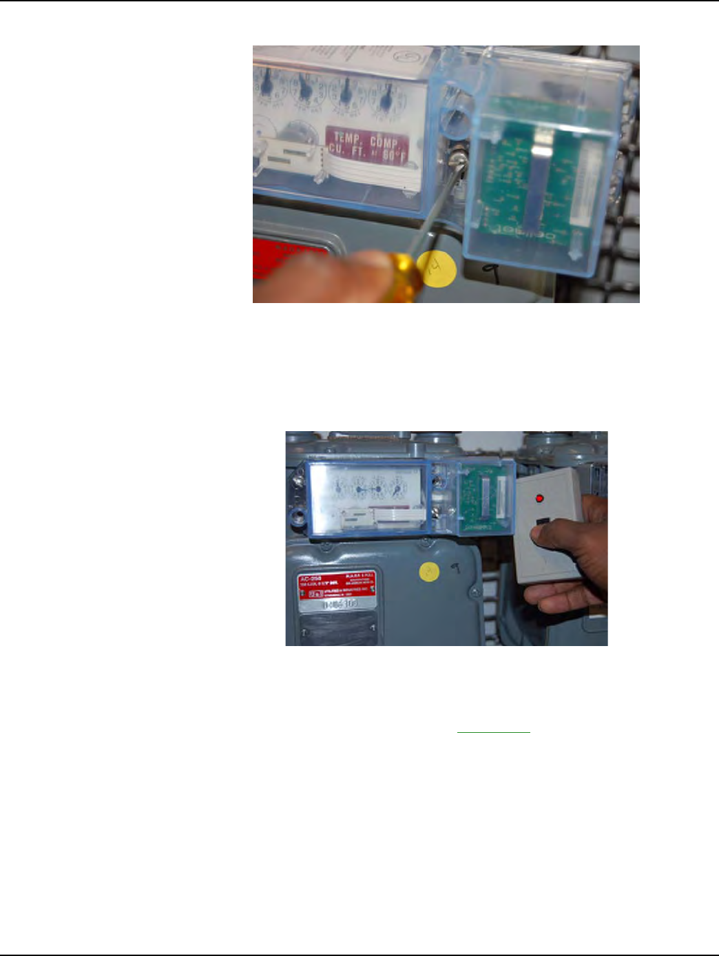
18 AfterbothscrewsaretightenedandtheMeterIndexisinstalled,positiontheGasLX
coverforinstallation.Install,butdonottightentomountingtorque,thefirstofthe
GasLXcovermountingscrews.
Figure 6 - 21. Installing the first Gas LX Cover mounting screw
Chapter 5 - Meter Module Retrofit Landis+Gyr
54 98-3107 Rev AA One-way Gas Module Installation Guide
Figure 6 - 22. Installing the next Meter Index Cover mounting screw
19 Installtheremainingscrews.Tightenthescrewsuntilthecoversitssnug,thentighten
thescrewsanadditionalquarterturn.Preparetoverifythatthemoduleis
transmitting.
Figure 6 - 23. RF Buster oriented to Gas LX Meter Module for testing
20 UsetheRFBustertoverifythatthemoduleistransmittingbyholdingtheRFBuster
withmagnetsidetothetopupperrightquadrantofthemoduleplastichousing.Hold
thebuttonuntil10beepsarereceived.SeeAppendix B,UsingtheRFBusterformore
information.
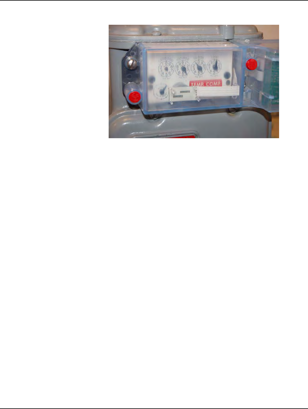
21 Installnewredtampersealsovertwodiagonalscrews(upperrightandlowerleft).
Landis+Gyr Chapter 5 - Meter Module Retrofit
One-way Gas Module Installation Guide 98-3107 Rev AA 55
Figure 6 - 24. Meter module with tamper seals installed
22 Cleanupdebrisfromtheretrofitandinstallationprocesses.Entertheappropriate
infomationonadoorhangertag.Adoorhangertagmustalwaysbeleftafterameter
isexchanged.
23 Attheendoftheday,theinstallerreturnstotheCrossDockforthecheck‐inprocess.
Theinstallershouldalsoturnininventoryofunused,defective,orbrokengasMeter
Modules.TheInstallermustcheckinallHandheldsissued.Theinstalleris
responsibleforreconcilinganydiscrepanciesinchangeddatabeforethecheck‐in
processcanbecompleted.MetersModuleswillnotbecheckedouttoaninstallerwho
hasnotcompletedthepreviousdayʹscheck‐inprocess.

Chapter 5 - Meter Module Retrofit Landis+Gyr
56 98-3107 Rev AA One-way Gas Module Installation Guide

7
One-way Gas Module Installation Guide 98-3107 Rev AA 57
Gas Meter Preparation
Program (GPrep)
The Gas Meter Preparation Program (GPrep) is a software tool that facilitates Landis+Gyr processes.
It also runs with water CPR modules. The data captured by GPrep is sent to RIMS to update the
Landis+Gyr and utilities databases. GPrep was developed for Gas LX, ResGas, C&I Gas
(Diaphragm), C&I Gas (Rotary), and Cellnet Pulse Recorder (CPR gas and water) modules to:
• Disassociate Module IDs from Meter IDs - “MRB (Material Repair Board) Mode” This feature
most commonly captures the record of disassociation when removing a module from the field.
• Validate the programmed LAN Address with the Power LAN Address label and verify that the
operational programmed parameters match those required. - “Inspect Mode”.
This feature is most commonly used when receiving meters from the factory with Landis+Gyr
modules already installed (OEM Meters) or when receiving Landis+Gyr retrofit modules
directly from Landis+Gyr’s manufacturer. Different utilities use different sampling procedures.
The meter shop should verify a percentage of inbound modules to ensure that the LAN Address
that is programmed into the gas module and matches the LAN Address on the label outside of
the module housing. The modules can also be inspected to verify that the correct Meter ID
format was used, that the rollover point is correct, and that the meter constant is correct.
• Program the module with operational parameters, including the meter-specific values such as
meter ID, rollover point, meter constant, and dial index reading (which for gas meters can be
non-zero) - “Program New or Re-Program Old Mode”.
This feature is used when assembling Landis+Gyr modules on meters in the meter shop and in
the field (for the O&M Processes).
• Save the inspection, programming, MRB disassociation record and index read results in separate
files for delivery to Landis+Gyr and the utility.
This can be an automatic process. It can be turned it off for a particular feature when it is not
necessary to save the results.
You can use GPrep in a meter shop, at a fixed location, or in the field. You can use a PC or laptop
computer. Closely monitor GPrep usage, and make the data files easily accessible. GPrep is often
used with operations and maintenance (O&M) processes. This chapter assumes that the user fully
understands these O&M processes, and at which steps in these processes GPrep captures data and
programs it into Landis+Gyr modules.
GPrep requires selective functionality depending on the site where it is in use, so there are
administrative privileges for configuring options during software installation and setup.
Each of these functions are steps in Landis+Gyr processes. You should fully understand
how data flows within the Landis+Gyr network and what data needs to be captured from or
programmed into a module before using this software.

Chapter 7 - Gas Meter Preparation Program (GPrep) Landis+Gyr
58 98-3107 Rev AA One-way Gas Module Installation Guide
Required Tools
The following is a list of required tools to operate GPrep, along with a PC / operating system
recommendation:
• Desktop PC with Windows 2000 or higher (Windows NT is not recommended when using a
laptop computer since there are sometimes problems configuring the ports)
• Copy of GPrep v. 2.3 or most recent version on a required tools CD
• Shooter Box with AC power cord, part number 26-3500 and gas shooter cable
or
1-Way Module Programming Cable PN 26-1179
• Battery, part number 40-1032 or 40-1590
•Laptop/PC
• DB9 to DB9 cable (male on one end female on the other) straight through (RS232).
Roles
•GPrep Administrator - is the local expert on GPrep. The Administrator is familiar with the
entire functionality of GPrep. The Administrator knows how to configure all internal files, and
how to grant certain permissions.
The Administrator knows how to clean all files of bad records and supersedes. How to archive
all files and e-mail them to the appropriate database administrator or RIMS analyst and how to
train the day to day users of GPrep. This person has the daily task of maintaining GPrep and its
files.
•GPrep User - needs to know the fundamentals of GPrep. They need to know how to log in, how
to marry a meter with a module, and how to inspect a module to ensure that it is properly
programmed, and what to do if it is not.
Procedures for GPrep Administrator
1Verifyyourtools.GPrepdoesnotoperatewithoutallofthetoolslistedintheRequiredTools
section.
2UnzipGPrepfilestoyourPCorlaptop.
aCustomizeGPrep.
TheGPrepinstallationfoldercontainsafilenamedGPREP.INI.Thisfiledefinesall
configurationparametersinits[Control]sectionandmaintainssettingsfromthelastGPrep
runinits[Default]section.
•Ifthisisanewinstallation,GPREP.INImustbecopiedtotheGPrepinstallationdirectory.
•Ifthisisanupgrade,thenyoucanusetheexistingGPREP.INIfiletomodifyany
configurationparametersasnecessary.
b EdittheGPREP.INIfileusingNotepadoryourpreferredASCIIfileeditor.
Before copying files go to “View” on the menu bar of your PC, select “Folder
Options”. Under a section titled “Advanced Settings” there is a folder called
“Hidden files”, under that folder choose “show all files”, then click on the OK
button.

Landis+Gyr Chapter 7 - Gas Meter Preparation Program (GPrep)
One-way Gas Module Installation Guide 98-3107 Rev AA 59
c FollowtheinstructionsinthatfiletospecifytherequiredpatternforMeterIDs,file(s)for
loggingoperations,menuselectionsthatareavailabletotheoperatorandthemaximum
memoryusedtotrackpreviouslogfileassociations.
Following is an example of a GPREP.INI file.
; The Default section remembers GPrep settings from the last run. These should
; not be changed manually.
; ------------------------------------------------------------------------------
[Default]
; The Control section contains GPrep operational parameters.
; ------------------------------------------------------------------------------
; Operator Meter Type selections are controled by variables:
;
; RGAS for ResGas
; CIGD for C&I Gas (Diaphragm)
; CIGR for C&I Gas (Rotary)
; CPRG for CPR Gas (Rotary)
;
; Setting any of these to "No" disables the menu item. The default is "Yes".
;
; Example:
; RGAS=No
; CIGR=Yes
; Disables "ResGas" selection, leaving both C&I and CPR selections enabled.
; ------------------------------------------------------------------------------
; Operator Mode selections are controled by variables:
;
; Inspect
; ProgramNew
; ProgramOld
; IndexRead
; MRBMode
;
; Setting any of these to "No" disables the menu item. The default is "Yes".
;
; Example:
; ProgramOld=No
; Inspect=Yes
; MRBMode=No
; Disables "Re-Program Old" and "MRB" selections, leaving "Inspect",
; "Program New" and "Index Read" modes enabled.
; ------------------------------------------------------------------------------
; Operator Port selections are controled by variables:
;
; COM1, COM2, COM3 and COM4
;
; Setting any of these to "No" disables the menu item. The default is "Yes".
;
; Example:
; COM4=No
; COM3=No
If you run GPrep in different modes and/or it requires different configuration settings at the
same operator station, then install multiple copies of GPrep in different directories.

Chapter 7 - Gas Meter Preparation Program (GPrep) Landis+Gyr
60 98-3107 Rev AA One-way Gas Module Installation Guide
; COM1=Yes
; Disables "COM3" and "COM4" selections, leaving "COM1" and "COM2" enabled.
; ------------------------------------------------------------------------------
; MeterID is a pattern string for scanned (or entered) Meter IDs. The length
; of the pattern gives the number of characters required and each character
; in the pattern corresponds to a character in the Meter ID; if it's:
;
; # - The character must be a decimal digit (0 - 9)
; $ - The character must be alphabetic (A - Z)
; _ - The character must be a blank
; ? - The character may be anything
; All other characters must match exactly.
;
; Note: If MeterID is not given then no pattern matching is done.
;
; Examples:
; MeterID=ABC### - IDs must must be 6 characters long, and start with
; "ABC" followed by 3 digits
; MeterID=Q???##_$$### - IDs must be 12 characters long, start with a "Q",
; followed by any 3 characters, then 2 digits, a space,
; 2 alphabetic characters, and end with 3 digits.
; MeterID=- IDs are not checked against a prototype, only for
; valid characters.
; ------------------------------------------------------------------------------
; ProgramLog is the full path and file name for logging each time a module is
; programmed. If not given, then no program log file is written.
;
; Examples:
;
; ProgramLog=c:\gprep\program.txt - program.txt in the gprep directory on drive C:
; ProgramLog=program.txt - program.txt in the GPrep program directory
; ProgramLog=program - program.txt in the GPrep program directory
; ProgramLog=- Do not write a program log file
; ------------------------------------------------------------------------------
; InspectLog is the full path and file name for logging each time a module is
; inspected. If not given, then no inspection log file is written.
;
; Examples:
;
; InspectLog=c:\gprep\inspect.txt - inspect.txt in the gprep directory on drive C:
; InspectLog=inspect.txt - inspect.txt in the GPrep program directory
; InspectLog=inspect - inspect.txt in the GPrep program directory
; InspectLog=- Do not write an inspection log file
; ------------------------------------------------------------------------------
; MRBLog is the full path and file name for logging each time a module is
; inspected in MRB Mode. If not given, then no MRB log file is written.
;
; Examples:
;
; MRBLog=c:\gprep\mrblog.txt - mrblog.txt in the gprep directory on drive C:
; MRBLog=mrblog.txt - mrblog.txt in the GPrep program directory
; MRBLog=mrblog - mrblog.txt in the GPrep program directory
; MRBLog=- Do not write an MRB log file
; ------------------------------------------------------------------------------
; ReadLog is the full path and file name for logging each time a module is
; inspected in Index Read Mode. If not given, then no read log file is written.
;
; Examples:
;
; ReadLog=c:\gprep\readdlog.txt - readdlog.txt in the gprep directory on drive C:
; ReadLog=readdlog.txt - readdlog.txt in the GPrep program directory

Landis+Gyr Chapter 7 - Gas Meter Preparation Program (GPrep)
One-way Gas Module Installation Guide 98-3107 Rev AA 61
; ReadLog=readdlog - readdlog.txt in the GPrep program directory
; ReadLog=- Do not write an inspection log file
; ------------------------------------------------------------------------------
; MaxAssociations is the maximum number of LANAddress / Meter ID associations
; checked from the log file to assure that duplications are not assigned.
; This requires 24 bytes of memory per association. Set to 0 to disable.
;
; Examples:
;
; MaxAssociations=1000 - Previous 1000 records are checked (memory = 24,000)
; MaxAssociations=10000 - Previous 10000 records are checked (memory = 240,000)
; MaxAssociations=0 - Disables duplication association checking.
; ------------------------------------------------------------------------------
Mode=ReProgram
ModuleClass=1
RolloverPoint1=1000000
MeterConstant1=0.050000
SerialPort=1
Operator=Bill
Location=xdcsu
Utility=SCG
RolloverPoint0=10000
MeterConstant0=0.020000
RolloverPoint3=100000
MeterConstant3=1.000000
RolloverPoint2=100000
MeterConstant2=0.100000
MeterConstant4=0.250000
ProgramMode=Yes
ProgramDial=Yes
RolloverPoint=100000
MeterConstant=1.000000
LastFile=WCPR.SET
[Control]
meterID=?????????
DeviceID=?????
RGAS=yes
CIGD=yes
CIGR=yes
CPRANT=yes
CPRAWT=yes
CPRCWT=yes
WCPR=yes
Inspect=yes
ProgramNew=yes
ProgramOld=yes
MRBMode=yes
IndexRead=N
ProgramLog=c:\programlog.txt
inspectLog=c:\inspectlog.txt
MRBLog=c:\MRBlog.txt
ReadLog=c:\readlog.txt
wProgramLog=c:\wprogramlog.txt
winspectLog=c:\winspectlog.txt
wMRBLog=c:\wMRBlog.txt
[RGAS]
MeterConstantCount=4

Chapter 7 - Gas Meter Preparation Program (GPrep) Landis+Gyr
62 98-3107 Rev AA One-way Gas Module Installation Guide
MeterConstant1=.01
MeterConstant2=.0112
MeterConstant3=.02
MeterConstant4=.0225
RollOverPointCount=5
RollOverPoint1=100
RollOverPoint2=1,000
RollOverPoint3=10,000
RollOverPoint4=100,000
RollOverPoint5=100000000
[CPRAWT]
MeterConstantCount=9
MeterConstant1=.01
MeterConstant2=.01121
MeterConstant3=.02
MeterConstant4=.0225
MeterConstant5=.05
MeterConstant6=.0562
MeterConstant7=.1
MeterConstant8=.112
MeterConstant9=1.0
RollOverPointCount=6
RollOverPoint1=100
RollOverPoint2=1,000
RollOverPoint3=10,000
RollOverPoint4=100,000
RollOverPoint5=100,00000
RollOverPoint6=100,000000
[CPRANT]
MeterConstantCount=10
MeterConstant1=.01
MeterConstant2=.01121
MeterConstant3=.02
MeterConstant4=.0225
MeterConstant5=.05
MeterConstant6=.0562
MeterConstant7=.1
MeterConstant8=.112
MeterConstant9=1.0
MeterConstant10=2.0
RollOverPointCount=5
RollOverPoint1=100
RollOverPoint2=1,000
RollOverPoint3=10,000
RollOverPoint4=100,000
RollOverPoint5=100,000,000
[CPRCWT]
MeterConstantCount=9
MeterConstant1=.01
MeterConstant2=.01121
MeterConstant3=.02
MeterConstant4=.0225
MeterConstant5=.05
MeterConstant6=.0562
MeterConstant7=.1
MeterConstant8=.112
MeterConstant9=1.0
RollOverPointCount=5

Landis+Gyr Chapter 7 - Gas Meter Preparation Program (GPrep)
One-way Gas Module Installation Guide 98-3107 Rev AA 63
RollOverPoint1=100
RollOverPoint2=1,000
RollOverPoint3=10,000
RollOverPoint4=100,000
RollOverPoint5=99999999
[CIGR]
MeterConstantCount=5
MeterConstant1=.05
MeterConstant2=.0562
MeterConstant3=.1
MeterConstant4=.112
MeterConstant5=1.0
RollOverPointCount=5
RollOverPoint1=100
RollOverPoint2=1,000
RollOverPoint3=10,000
RollOverPoint4=100,000
RollOverPoint5=100,0000
[CIGD]
MeterConstantCount=5
MeterConstant1=.05
MeterConstant2=.0562
MeterConstant3=.1
MeterConstant4=.112
MeterConstant5=1.0
RollOverPointCount=5
RollOverPoint1=100
RollOverPoint2=1,000
RollOverPoint3=10,000
RollOverPoint4=100,000
RollOverPoint5=100,0000
[WCPR]
MeterConstantCount=1
MeterConstant1=1
RollOverPointCount=5
RollOverPoint1=100
RollOverPoint2=1,000
RollOverPoint3=10,000
RollOverPoint4=100,000
RollOverPoint5=100,0000
Save your updates to the GPrep.ini file. GPrep is ready to use.
Data Transfer
A local RIMS analyst performs this process. The RIMS Analyst uploads MRB and Program files to
the server via FTP.
Server Side Process
The person using GPrep, or the local administrator, posts the program log and MRB files to
Landis+Gyr's FTP Server. You can use any SFTP Tool to post files from gas and water processes.
The GPREP.ini file determines the name and path of the files generated in the local machine. Each
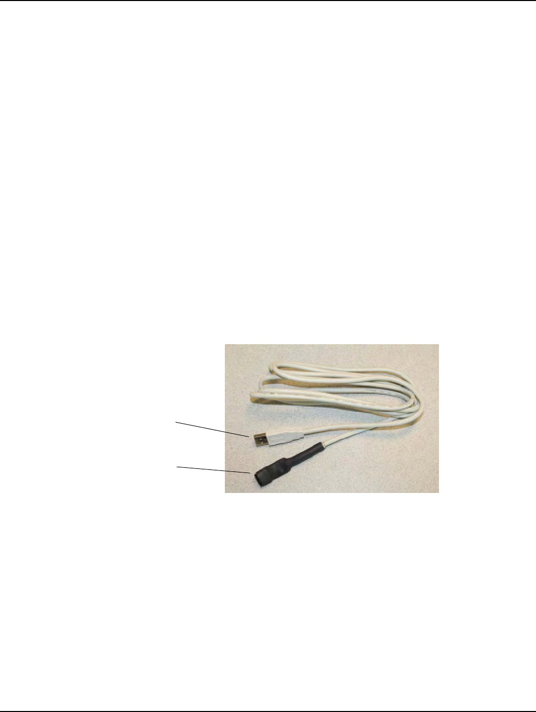
Chapter 7 - Gas Meter Preparation Program (GPrep) Landis+Gyr
64 98-3107 Rev AA One-way Gas Module Installation Guide
Utility shop location can post multiple files, as long as each file is uniquely identified. The local site
can use any logic to name these files, preferably to include date and time.
Once these files are posted, the DES server validates file format and cleanup activities by
eliminating duplicate entries and storing the program logs and MRB data in staging tables. The
server emails subscribers from source location. RIMS CRON runs nightly, processing meters and
updating the latest associations to OCDB.
Using GPrep
This section details the steps taken by the end user to operate GPrep on a daily basis. This set of
procedures assumes the following:
• Your GPrep administrator has configured the .ini file.
• You have basic knowledge of the process that you are trying to perform and understand at which
step of the process you need to use GPrep.
• Shooter box or 1-way programming cable
If you are using the programming cable (usually in the field):
1Installdriversandsetupthecableperinstructionsinthe1‐WayModuleProgrammingCable
GettingStartedGuide.
2Plugoneendofthecableintothemodule.
3PlugtheUSBintothelaptoporPC.
Figure 7 - 1. One-Way Programming Cable
If you are using the shooter box (usually in the office or shop):
1Plugthebatteryintotheshootercable.
2Powertheshooterbox.
3 ConnecttheshooterboxtoaCOMportonyourPCandchoosethecorrectCOMportfromthe
dropdownmenuonGPrep(oritdefaultstothatport).
4Plugtheshootercableintotheshooterboxandthemodule
USB Connector
Module Connector
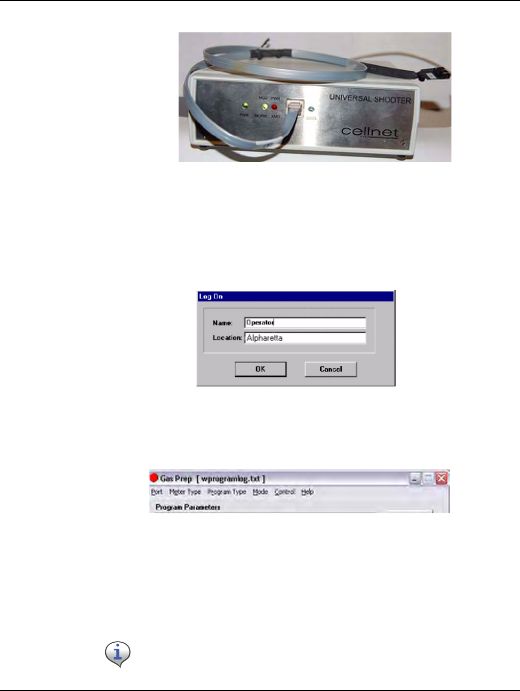
Landis+Gyr Chapter 7 - Gas Meter Preparation Program (GPrep)
One-way Gas Module Installation Guide 98-3107 Rev AA 65
.
Figure 7 - 2. Shooter box with data cable
Logging On
The Log On window displays when you launch the program.
Enter your name and location in the appropriate fields. All tasks you perform for a given meter type
(module inspection, new module programming, old module reprogramming, MRB and index read)
will be recorded.
Figure 7 - 3. Log On screen
Accessing the Main Menu
The main menu screen displays after you log on.
Figure 7 - 4. GPrep Menu Bar
The GPrep menu bar includes the following options:
Port: enables the operator to select the PC port (usually COM: 1).
Meter type: Enables the operator to select meter type from the drop-down list. The options consist
of Gas LX, ResGas, C&I Gas (Diaphragm), C&I (Rotary), CPR Form A No Tamper, CPR Form B
Tamper, CPR Form C Tamper, and CPR Water.
Certain sites may not use all options.

Chapter 7 - Gas Meter Preparation Program (GPrep) Landis+Gyr
66 98-3107 Rev AA One-way Gas Module Installation Guide
Program Type: Select Interval or Consumption type data.
Mode: provides the following choices:
•Inspect: Verifies that the programmed LAN Address has the same value as the Power LAN
Address label. In addition, “Inspect” permits validating the other pre-configured operational
parameters. Discrepancies are noted through message windows and the results of inspections are
captured in associated files.
•Program New: provides the capability to program a new meter for a specified rollover point and
a meter constant for a specific utility meter ID format.
•Re-Program Old: provides the capability to program a meter with a non-zero index. This option
was designed for utility meter shops to reprogram meter-modules pulled from the field or
program a non-zero index read. All other features for this option are similar to the Program New
mode. The “programlog.txt” file also includes the index read entered during the programming
step as the field “opening read”.
•MRB: captures the disassociation record for meters returned from the field. This option is
mainly designed for meter shop use during the O&M phase.
The unique meter ID format for a given utility is defined in the “.ini” file. Any discrepancy
in the meter ID format is noted in a message window, which prompts the operator to
re-enter the meter ID prior to module programming. The association record of
meter ID, module LAN Address, date, operator’s name, and result of operation is
captured in the file “programlog.txt”.
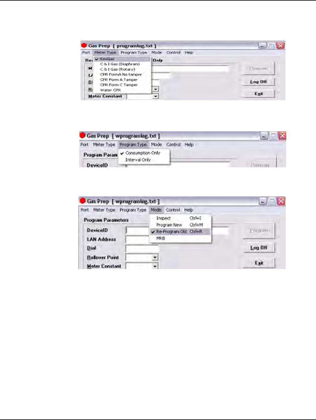
Landis+Gyr Chapter 7 - Gas Meter Preparation Program (GPrep)
One-way Gas Module Installation Guide 98-3107 Rev AA 67
The following screens show how the operator has the option of choosing inspect, program new, and
index read when Gas LX is chosen as the Meter Type.
Figure 7 - 5. Choose Gas LX as the meter type
Figure 7 - 6. Indicate the Program Type
Figure 7 - 7. Modes to choose from are “Inspect” or “Program New”
•Control: provides the capability to log on and off. The program setting remains the same when a
new operator logs on.
•Help: provides a description of GPrep functionality for each mode of operation (not yet fully
implemented).
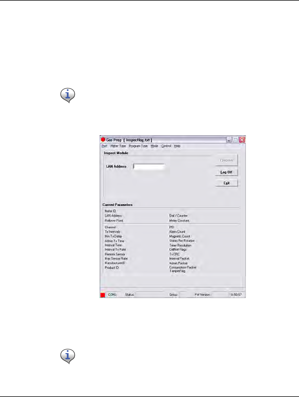
Chapter 7 - Gas Meter Preparation Program (GPrep) Landis+Gyr
68 98-3107 Rev AA One-way Gas Module Installation Guide
Module Inspection
This feature is most commonly used when receiving meters from the factory with Landis+Gyr
modules already installed (OEM Meters) or when receiving Landis+Gyr modules from
Landis+Gyr’s manufacturer. Different utilities use different sampling procedures. Landis+Gyr
recommends that the meter shop verify a percentage of inbound modules to ensure that the LAN
Address that is programmed into the module matches the LAN Address on the outside of the module
housing. The modules can also be inspected to verify that the correct Meter ID format was used, that
the rollover point is correct, and that the meter constant is correct.
1SelectInspectfromtheModedrop‐downwindowinthemainmenu.Thefollowingscreen
displays.
Figure 7 - 8. GPrep “Inspect Mode” screen
There are two distinct sections on the screen. The top section is the LAN Address field where the
module power LAN label is either scanned or typed.
Different modes of operation for Gas LX modules are provided in detail. All other meter/
module types follows the identical functionality and operations, except as noted for Water
CPR.
The program automatically truncates the leading zeros and any blank spaces in the LAN
Address field. GPrep left justifies the value in this field.
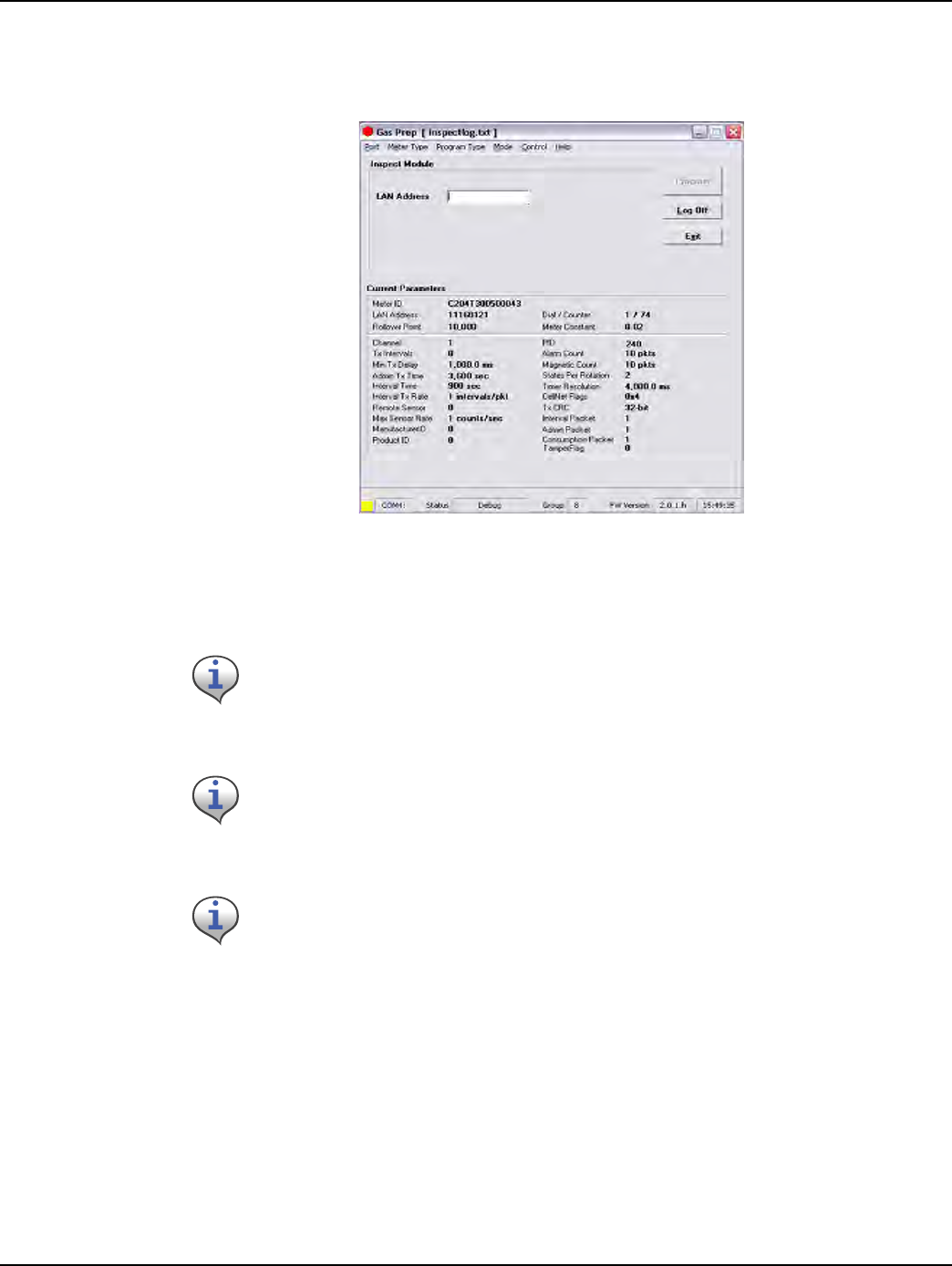
Landis+Gyr Chapter 7 - Gas Meter Preparation Program (GPrep)
One-way Gas Module Installation Guide 98-3107 Rev AA 69
The lower section, “current parameters”, displays the operational parameters and module
programmed values.
2 Connecttheshootercabletothemoduleprogrammingport.Thefollowingscreendisplays.
Figure 7 - 9. “Inspect Mode” Screen With Module Plugged In
GPrep automatically reads and displays the current parameters programmed into the module.
If the Meter Type selected does not match the module under test, GPrep displays a dialog
box indicating “wrong module Type” along with a blinking “Module reject” message. GPrep
does not allow the operator to continue with this function.
If the current parameters do not match the predetermined values, a warning message
displays. (This is normal for new modules because a module coming from the
manufacturer is programmed with test parameters).
Module PCB ID (board ID) is populated during manufacturing. Upon verification of module
inspection, this value is saved in combination with the module Power LAN Address in the
Inspect file along with date, operator’s name and location of inspection.
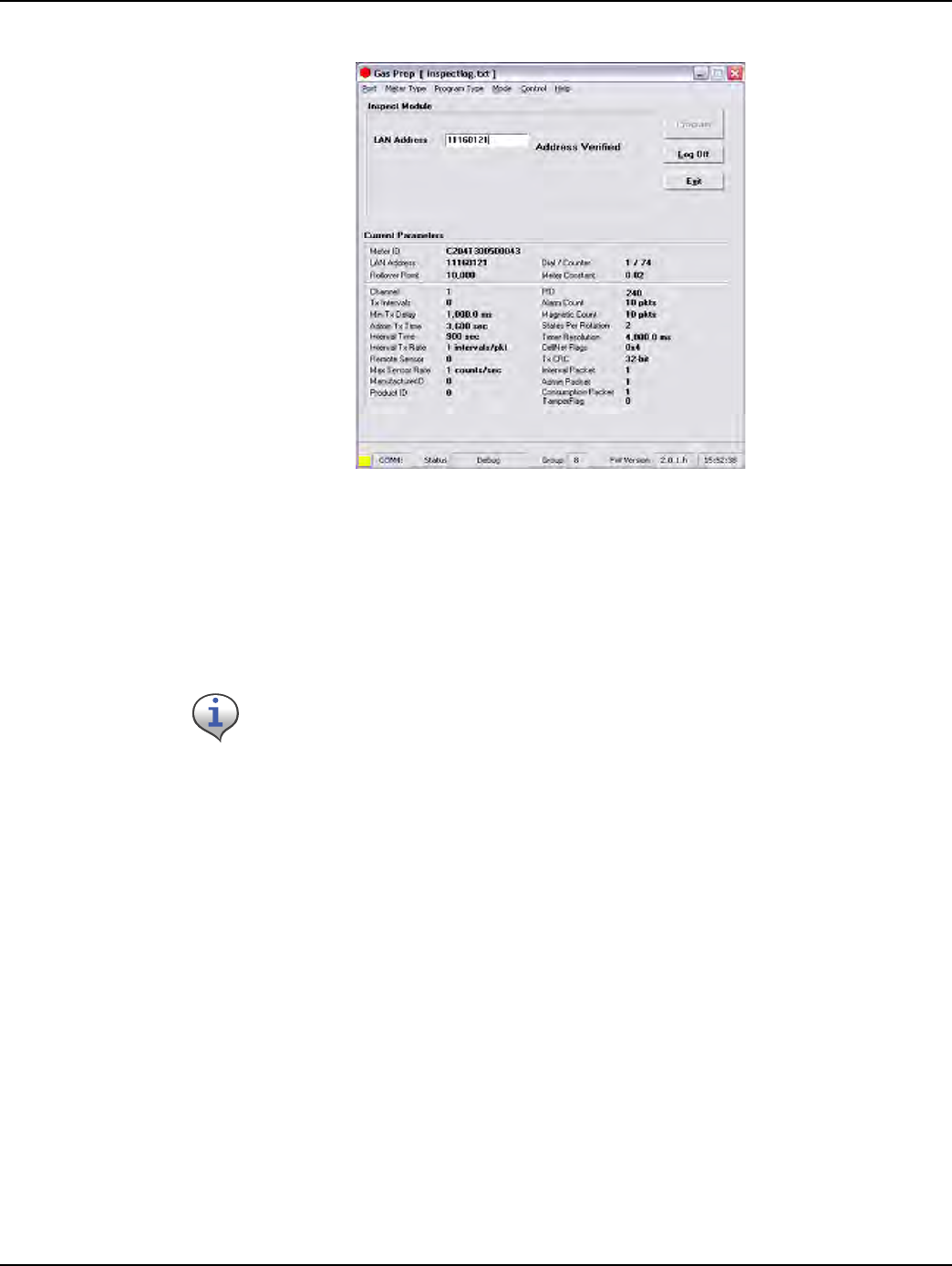
Chapter 7 - Gas Meter Preparation Program (GPrep) Landis+Gyr
70 98-3107 Rev AA One-way Gas Module Installation Guide
3Scan(enter)theModuleIDinLANAddressfield.
Figure 7 - 10. “Inspect Mode” With Power LAN Scanned In
GPrep compares the Module ID entered in this field with the LAN Address programmed into the
module. If the populated field matches the programmed value, a message displays “address
verified”. If the entered value does not match the programmed value a dialog box displays, stating
the “LAN Address does not match the programmed value” and instructs the operator to reenter the
power LAN label value, due to a misinterpretation or mis-entered value. GPrep instructs the operator
to route the module to MRB for further disposition if the entered values do not match again.
If the power LAN value does not match the programmed value, a record is also generated in the
“inspect file” showing the inspection has failed. Modules that fail inspection must be segregated and
routed to MRB.
Module Programming
There are two modes for programming the modules. Program New is used when a module is
installed on a new meter with an index that reads zero, and Re-program old is used for
programming a module that is being installed on a meter that has an index with a value other than
zero. This value is programmed into the module to log in the starting read for a meter to be installed.
(An example of this is a periodic meter check in which a meter is taken from a residence, inspected
and then re-deployed again into another residence).
Program New
1SelectProgramnewfromthemodedrop‐downwindowinthemainmenu.Thefollowing
screendisplays.
If the result of the inspection is verified, a record in the “inspect file” is created showing
that the module Inspection is successful. It also captures the PCB ID of the module in the
same record.
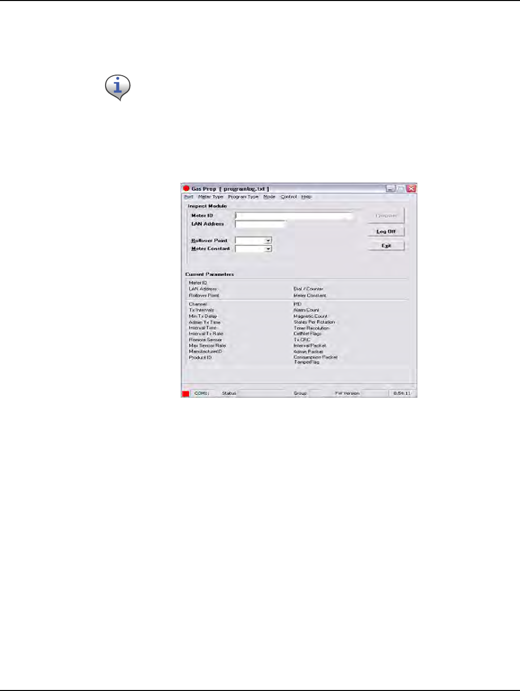
Landis+Gyr Chapter 7 - Gas Meter Preparation Program (GPrep)
One-way Gas Module Installation Guide 98-3107 Rev AA 71
There are two distinct sections in this screen as well. The top section contains the following fields
which can be modified by the user:
• Meter ID field
• LAN Address
• Roll-over point
• Meter constant.
Figure 7 - 11. “Program New” Screen
If you are programming a Water CPR module, Device ID replaces Meter ID. A CPR module is
programmed with 10-digit left-justified (zero) Module ID as MeterID. Water CPR
programming also captures optional Encoder ID information.
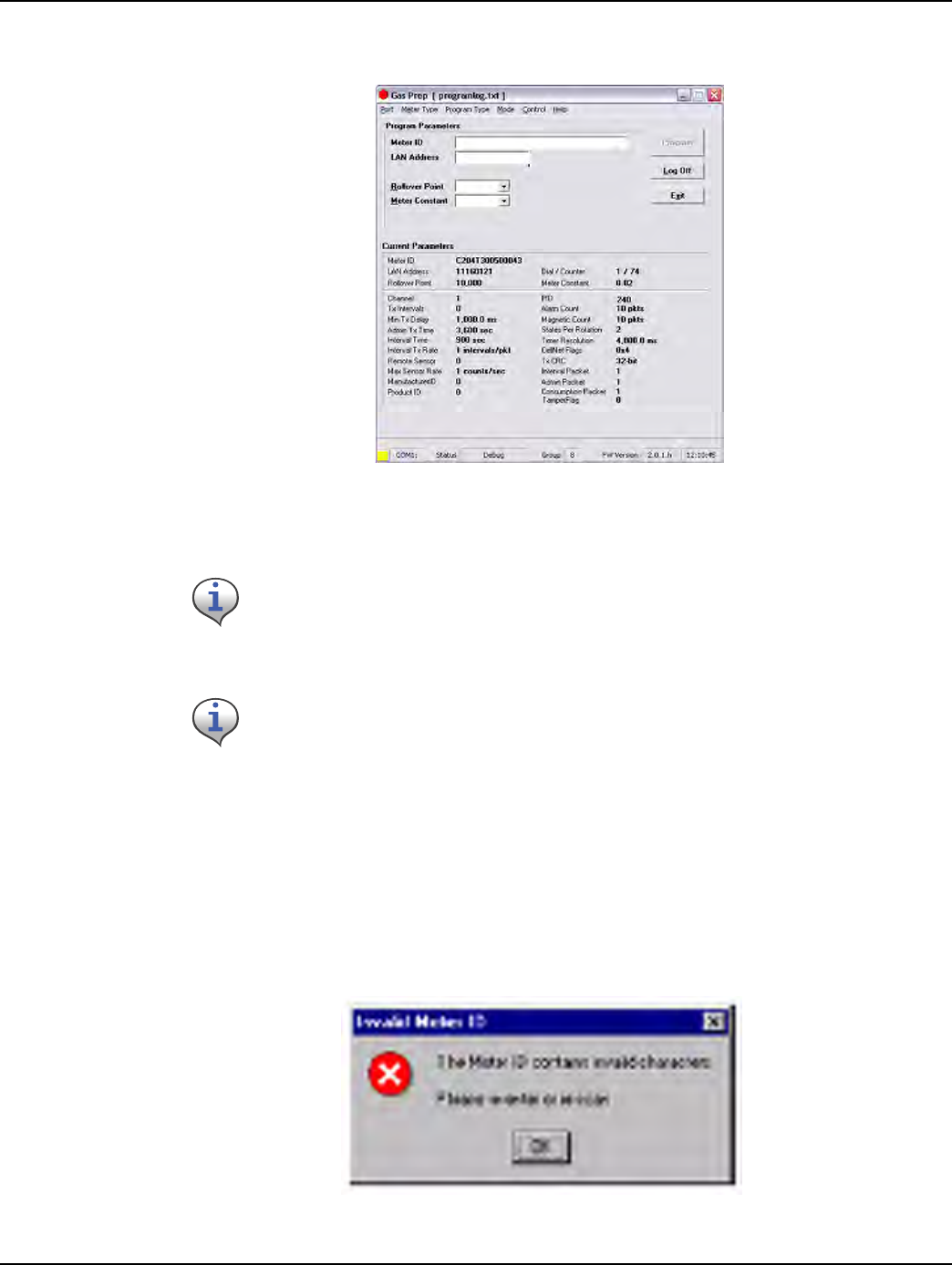
Chapter 7 - Gas Meter Preparation Program (GPrep) Landis+Gyr
72 98-3107 Rev AA One-way Gas Module Installation Guide
2 Connectthe1‐WayProgrammingCableorshootercabletothemoduleprogrammingport.The
followingscreendisplays.
Figure 7 - 12. “Program New” Screen with Module Plugged In
GPrep automatically reads and displays the current parameters programmed into the module.
3ScanorenterthemeterIDinappropriatefield.
Since the meter ID field is utility specific, there are provisions within GPrep to specify the meter ID
format. Therefore, if the meter ID format entered in this field does not match the specified utility
format, a dialog window displays indicating “meter ID field contains invalid characters” and the
operator is instructed to either rescan or re-enter the meter ID value in this field. Module
programming can not be resumed until the meter ID field populated matches the utility specific
format.
Figure 7 - 13. Error Message Displayed when The Wrong Meter ID Format Is Entered
If the Meter Type selected on the menu bar does not match the module type under test,
GPrep displays a dialog box indicating “wrong module Type” and a blinking “Module
reject” message. GPrep does not allow the operator to resume the programming function.
If the current parameters do not match the predetermined value, a warning message,
“reject parameters” displays. Upon successful completion of module programming, GPrep
populates the “current parameter” fields with correct operational values.
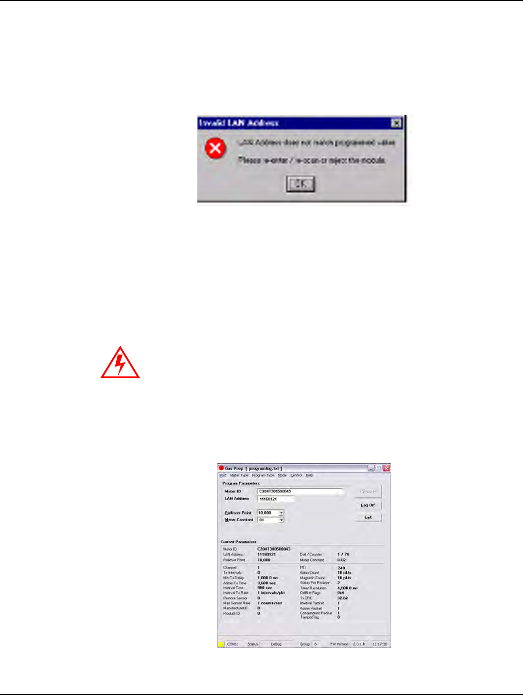
Landis+Gyr Chapter 7 - Gas Meter Preparation Program (GPrep)
One-way Gas Module Installation Guide 98-3107 Rev AA 73
4Scan(enter)thepowerLANlabelintheLANAddressfield.
“GPrep” compares the value entered in this field with the LAN Address programmed in the module.
Similar to the inspection section, any discrepancies in the values are rejected.
Figure 7 - 14. Error Message Displayed if The Scanned Power LAN Value Does Not Match the
Programmed Value
Select the Rollover Point and Meter Constant (meter specific values) prior to programming the
module from the drop-down windows. GPrep displays a message window verifying that the operator
intends to change the Rollover point and meter constant. GPrep keeps the last value entered in the
rollover point and meter constant fields as the default value.
Upon successful programming, a message “program verified” displays. GPrep also displays a green
square indicator at the lower left corner of the screen showing programming has been successful.
Figure 7 - 15. Display when parameters are verified
If you do not know what to enter for the Rollover Point or Meter Constant STOP!
Contact someone that does know or contact Landis+Gyr Customer Support. The
wrong data entered in these fields significantly affects the billing read provided to
the utility.
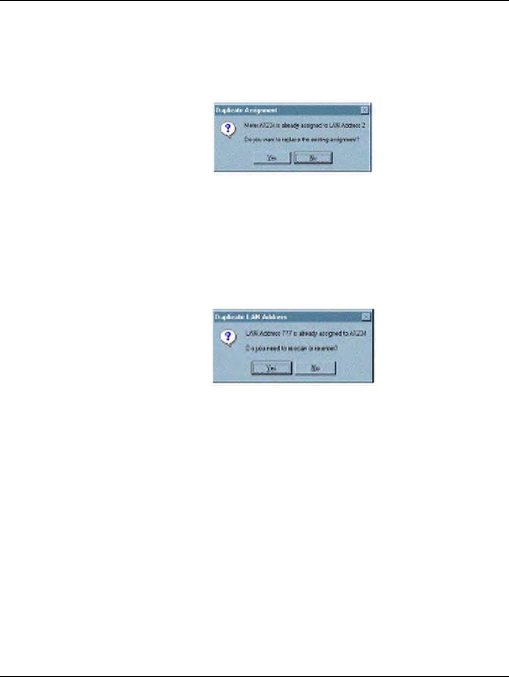
Chapter 7 - Gas Meter Preparation Program (GPrep) Landis+Gyr
74 98-3107 Rev AA One-way Gas Module Installation Guide
A record of the meter and module association is automatically captured in the “program file”
including the date and the operator’s name.
The “Programlog” only compiles the records when successful programming is verified. If a Meter
ID record already exists in programlog, the following message displays.
Figure 7 - 16. Error Message Indicating that a Meter ID Already Exists in the Programlog
• If you select “Yes”, a new record is inserted with a timestamp. It is a valid new record if the
program indicates “successful”. If you select “No”, the old record remains.
• If a record already exist in the programlog for a scanned module Power LAN Address, GPrep
displays the following message:
Figure 7 - 17. Duplicate Power LAN Address
• If you select “yes”, indicating that you entered the wrong module ID, then re-enter the meter ID
field and Power LAN Address to correct possible mis-entered values.
• If you select “No”, indicating the module ID has been entered correctly, GPrep displays a
blinking message “route to MRB”.
The result of this operation is not captured in the GPrep programlog file.
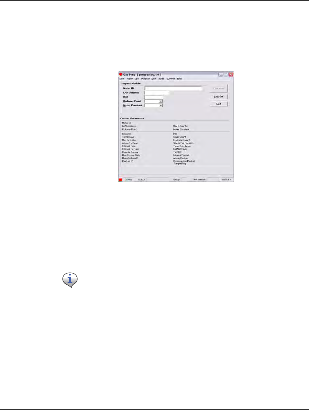
Landis+Gyr Chapter 7 - Gas Meter Preparation Program (GPrep)
One-way Gas Module Installation Guide 98-3107 Rev AA 75
Re-Program Old
The instructions and procedures for Re-Program Old are the same as those for Program New, with
the additional field “Dial”. Populate it with the index reading (dial reading). This mode is mainly
utilized during the O&M phase to program meters with non-zero indices.
1SelectRe‐ProgramOldfromthemodedrop‐downwindowinthemainmenu.Thefollowing
screendisplays.
Figure 7 - 18. “Re-Program Old” Screen
There are two distinct sections in this screen as well. The top section contains the following fields
which can be modified by the user:
• Meter ID field
• LAN Address
•Dial
• Roll-over point
• Meter constant
These are the only fields that can be populated.
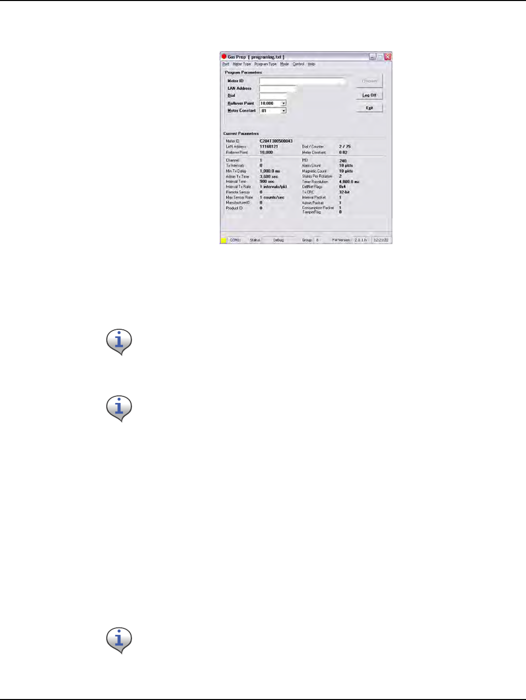
Chapter 7 - Gas Meter Preparation Program (GPrep) Landis+Gyr
76 98-3107 Rev AA One-way Gas Module Installation Guide
2 Connectthe1‐WayProgrammingCableorshootercabletothemoduleprogrammingport.The
followingscreendisplays.
Figure 7 - 19. Re-Program Old With Module Plugged In
GPrep automatically reads and displays the current parameters programmed into the module.
This functionality ensures that the correct meter type is chosen for a given meter.
3Scan(enter)themeterIDinappropriatefield.
SincethemeterIDfieldisutilityspecific,thereareprovisionswithinGPreptospecifythemeter
IDformat.Therefore,ifthemeterIDfieldformatenteredinthisfielddoesnotmatchthe
specifiedutilityformat,adialogwindowdisplaysindicating“meterIDfieldcontaininvalid
characters”andtheoperatorisinstructedtoeitherrescanorre‐enterthemeterIDvalueinthis
field.ModuleprogrammingcannotberesumeduntilthemeterIDfieldpopulatedmatchesthe
utilityspecificformat.
4Scan(enter)theModuleIDinLANAddressfield.
GPrep compares the value entered in this field with the LAN Address programmed in the module.
Similar to inspection section, any discrepancies in the values are rejected.
If the current parameters do not match the predetermined value, a warning message,
“reject parameters” displays. Upon successful completion of module programming,
“GPrep” populates the “current parameter” fields with correct operational values.
If the meter type selected from the “meter type” drop-down menu does not match the
module type, GPrep displays a message “wrong module type” and a blinking message
“reject module”.
Select the Rollover point and meter constant (meter specific values) prior to programming
the module from the drop-down windows. “GPrep” displays a message window verifying if
indeed the operator intends to change the Rollover point and meter constant. “GPrep”
keeps the last value entered in rollover point and meter constant fields as default value.
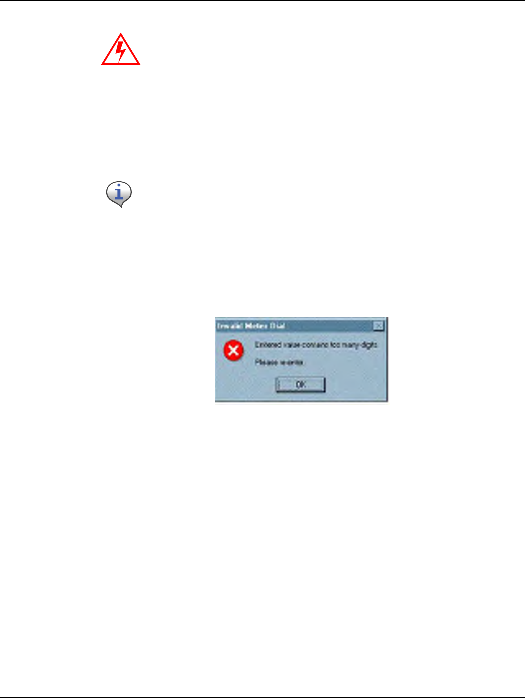
Landis+Gyr Chapter 7 - Gas Meter Preparation Program (GPrep)
One-way Gas Module Installation Guide 98-3107 Rev AA 77
5Entertheindexdialvaluesbyreadingthedialsandenteringthevaluesreadfromrighttoleft.
Figure 7 - 20. Error Message Displayed when Entered Read is too large for the Rollover Point
Select the proper Meter Constant from the drop-down box. You can typically determine the Meter
Constant from the meter index.
Upon successful programming a message “program verified” displays. GPrep also displays a green
square indicator at the lower left corner of the screen showing that the programming has been
successful (this is the same as the “verified” screen for Program New). A record of meter and
module association is automatically captured in the “programlog” including the index read entered
by operator as opening read.
MRB Mode
MRB (Material Repair Board) Mode captures the record of meter-module disassociation
disassembly as the modules are removed from the meters.
1Selectthemetertypefromthemenubarcorrespondingtothemeter–modulecombination.
If you do not know what to enter for the Rollover Point or Meter Constant STOP!
Contact someone that does know or contact Landis+Gyr Customer Support. The
wrong data entered in these fields significantly affects the billing read provided to
the utility.
The value entered in the dial field is programmed into the module as the starting meter
read at installation. Consumption is based on the initial read programmed into the module.
It is very important to be accurate on the dial index read. Note also that the dial field
requires the number of digits that correspond to the roll over point.
Example: If the roll over point is set at 10,000, then a four digit dial read would need to be
entered.
The index must have four dials if the roll over point of 10,000 is correct. Otherwise, the roll
over point must be changed accordingly. If the index read number contains more digits
than the corresponding rollover point, GPrep displays the following message prompting the
operator to reenter the index read and a blinking message in the main screen “dial
rejected” is also displayed.
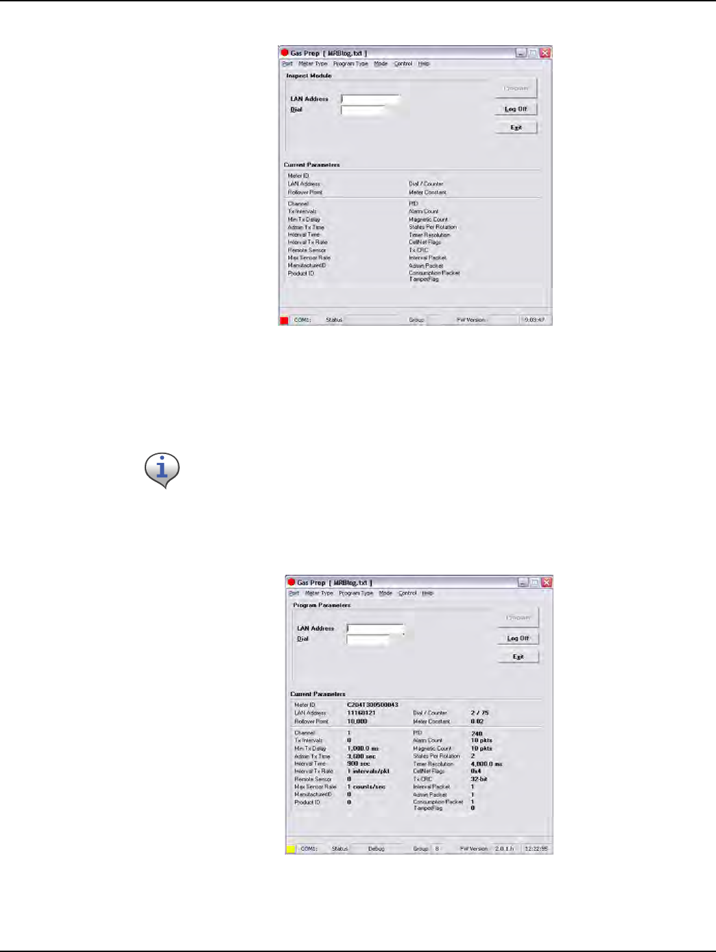
Chapter 7 - Gas Meter Preparation Program (GPrep) Landis+Gyr
78 98-3107 Rev AA One-way Gas Module Installation Guide
2SelectMRBfrommodeinthemenubar.Thefollowingscreendisplays.
Figure 7 - 21. MRB Mode Main Menu
There are two distinct sections on this screen as well. The top section contains the following fields:
• LAN Address
•Dial
3 Connectthe1‐WayProgrammingCableorshootercabletothemoduleprogrammingport.The
followingscreendisplays.
Figure 7 - 22. MRB Screen with Module Plugged In
These are the only fields that can be populated.
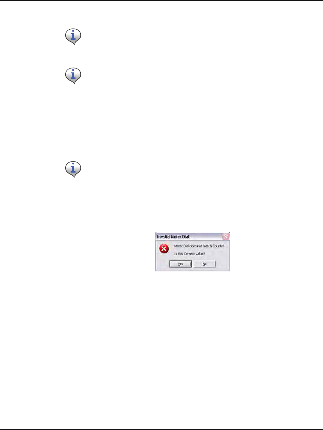
Landis+Gyr Chapter 7 - Gas Meter Preparation Program (GPrep)
One-way Gas Module Installation Guide 98-3107 Rev AA 79
4Scan(enter)theModuleIDinLANAddressfield.
GPrep compares the value entered in this field with the LAN Address programmed in the module.
GPrep rejects any discrepancies in values, and prompts you to re-enter the LAN Address or reject the
module.
5Entertheindexdialvaluesbyreadingthedialsandenteringthevaluesreadfromrighttoleft.
Figure 7 - 23. Error Message Displayed when Entered Value Does Not Match Programmed Value
If you select “Yes”, GPrep displays a blinking message stating “Dial discrepancy” and the main
screen displays that the new dial value has been logged in MRBlog. This is captured in the MRBlog
as “dial Entered”. GPrep does not capture the old value that was programmed into the module.
If you select “No”, GPrep prompts the operator to enter the correct value.
Upon acceptance of entered values for LAN Address and dial, GPrep creates a record in the MRB
including the closing index read and “Dial Verified” in addition to the association records.
The dial field requires the number of digits that correspond to the roll over point previously
programmed into the module. Example: If the roll over point is set at 1,000, then a four digit dial (or
less) read would need to be entered. The index must have four dials if the roll over point of 10,000 is
correct. If the index read number contains more digits than corresponding rollover point, GPrep
displays a message “entered value contains too many digits” prompting the operator to re-enter the
index read and a blinking message in the main screen “dial rejected” is also displayed.
If the Meter Type selected on the menu bar does not match the module type under test,
GPrep displays a dialog box indicating “wrong module Type” and a blinking “Module
reject” message. GPrep does not allow the operator to resume programming function.
If the current parameters do not match the predetermined value, a warning message,
“reject parameters” displays.
The value entered in the dial field are be compared with the module’s programmed read.
GPrep displays the following screen if there is any discrepancy and provides the option to
change the dial read if the operator has entered the wrong value

Chapter 7 - Gas Meter Preparation Program (GPrep) Landis+Gyr
80 98-3107 Rev AA One-way Gas Module Installation Guide
Frequently Asked Questions
1WhatdoesGPrepstandfor?
GasTOMMPreparation
2WhatisGPrepusedfor?
GPrepisatoolusedintheCrossDockormetershoptoprogramgasorwaterCPRmodules
withouttheuseofahandheld.ItisalsousedtodisassociategasorwaterCPRmodulesfrom
meters.
3Whatisprogrammedintothemodule?
Inthe“ProgramNew”and“Re‐ProgramOld”modes,fieldoperatingparametersare
programmedintothemodule.MeterID,RolloverPoint,DialRead,andMeterConstantarethe
onlyparametersthatcanbechangedbytheoperator.
4Howdoesameterconstantwork?
Ameterconstantisamultiplierthatconvertsthepulses/turnsofthemoduleintocubicfeet.The
reasonforthemeterconstanttobe.02onameterwitha2ftdriveisthatforeveryrotationofthe
drivedogtherehaspassed2cubicftofgas.Thisisequivalentto2%or.02or2/100thsof1point
onthesmallestofthefourdials,whichmeasureshundredsofcubicfeet.Forevery50rotations
ofthe2‐ftdogdial100cubicfeetofgashaspassed.Forevery50rotations,the1,000dialhas
increased1point(100cubicfeet)andourmodule(ifithappenstotransmitatthatmoment)
sendsoutapacketwithacountof50.OCDBmultipliesthe50bythemeterconstant.02togeta
readof1,whichwepassontotheutilityasareadof1forthatmeter.Therefore,ifthemeter
constantwerefalselysetto.01the50rotationswouldbemultipliedby.01andwouldonlyshow
thatthemeterused50cubicfeetofgas.
5WhydonʹtyouprogramthemeterIDfromthefrontofthemeterintothemodule?
The“UtilityBillingID”getsprogrammedintothemeter;thisisnotusuallythesameasthe
MeterID.
6Whatisarolloverpoint,howisitused,andwhyisitimportanttomakesurethatitisright?
Therolloverpointisthenumberatwhichthedialsofameterturnoverandstartatzeroagain.
Forafour‐dialmeter,thenumbersonthedialscannotgoover9999.Therefore,therollover
pointis10000.Forfive‐dialmeterstherolloverpointis100,000,etc.Itisimportanttoprogram
thecorrectrolloverpointintothemodulesothatoursystemreadmatchesthedialplate.
7WhatscreenshouldIuseinthesamplingprocess?
Thereareseveraldifferenttypesofsamplingdonebythemetershop.Usingthe“inspect”mode,
themostcommonsampleLandis+Gyr‐readyOEMmetersandsamplingmodulesfroma
Landis+Gyrmanufacturer.
8Whoisresponsiblefortransferringthedatafiles,howoftenarethedatafilestransferred,and
whowritesthescriptstopickupthedatafromtheserver?
ThelocaldatabaseanalystisusuallyresponsiblefortransferringthedatafromGPreptoRIMS.
Datatransfershouldbedoneeverydaythatthereisdataavailabletotransfer.Adatabasegroup
memberwritesthescripttoautomaticallypickupthisdata.
9Howsoondoesthedatagetupdatedineachsystemafteramoduleisprogrammed?
ACRONjobrunsnightlythatpicksupdataputontheLandis+Gyrserverandtransfersitto
RIMS.Ataminimumthereisaonedaydelay.
10 Whyshouldn’tItakeGPreptothefield?
DatamanagementbecomesdifficultwhentheGPrepPCisnotatafixedlocation.Thedata
capturedbyGPrepistimesensitivecustomeraccountinformationthatshouldbecopiedand
transferreddaily.TheequipmentusedtooperateGPrepisnotmadetobeusedoutdoors.If
GPrepistakentothefield,itisvitalthatthedatabetransferredassoonaspossibleuponreturn.
11 WhatdataiscapturedbyGPrep?
Thereiscurrentlynoscreenthatcapturesboththeclosingandopeningreadsonamodule(as
neededforindexchanges).MRBmodeshouldbeusedtodisassociatethemodulefromthe
meterandcapturetheclosingread.Program‐oldshouldthenbeusedtore‐programthemodule
withthenewindexread.

Landis+Gyr Chapter 7 - Gas Meter Preparation Program (GPrep)
One-way Gas Module Installation Guide 98-3107 Rev AA 81
12 WhataresometroubleshootingstepsifGPrepisnotworking?
–Ifyouareusingtheshooterbox,check:
—ACpower
—modulepluggedin
— shooterboxturnedon
— correctDB9toDB9(RS‐232)cable(Non‐NullModem)
— correctCOMport
— correctmetertypeandmode(e.g.GasLXv.commercial)
–IfyouareusingUSBonewayprogrammingcable,refertothe1‐WayModuleProgramming
CablePC/LaptopGettingStartedGuide.
13 Whatarethebenefitsofusingre‐programoldallofthetimeasopposedtoprogramnew?
Whilesomeprogramsdothis,therearenorealbenefits.Itisalittleeasiertopreparethe
programlogtosend,butinvolvesextraworkfortheenduser.
14 Whatdoesitmeanwhenafileissuperseded?
AmeterIDorLANAddresshadtobere‐entered.
15 Whoisresponsibleforcleaningthesefiles(removingsupersedes,convertingintoanExcel
spreadsheet,etc.)?
Typically,theutilitydesignatedpersonneltoperformthistaskbeforesendingthesefilestothe
databaseanalyst.
16 WhoshouldIcontactifthereisaproblem?
Contactalocaldatabaseanalyst.Ifneeded,contactLandis+GyrCustomerSupportat
ëçäìíáçåëìééçêíKå~]ä~åÇáëÖóêKÅçã.
17 Whenusingdifferentscreens,whydoesthephrase“parameterreject”flashyellowwhenIplug
inamodulethathasjustcomefromthemanufacturer?
Whenmodulesaremanufacturedandconfigured,testparametersareprogrammedtomakethe
moduletransmitmorefrequentlythanevery15minutes.Theseparametersalsoallowother
teststoberunonthemodulesforqualitycontrolprocedures.GPrep(orahandheld)replaces
thesetestparameterswithfieldparameters.
Notes:
82 One-way Gas Module Installation Guide
Gas Meter Preparation Program (GPrep)
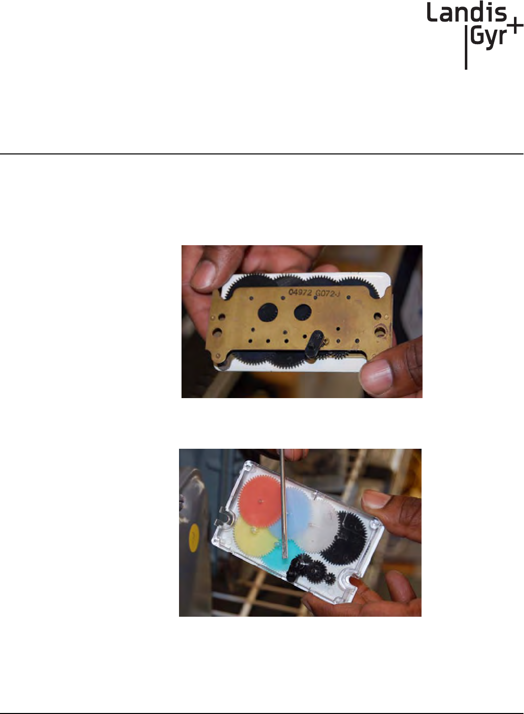
A
One-way Gas Module Installation Guide 98-3107 Rev AA 83
Supplemental Information
About Indexes
Index Type
Metal indexes cannot be used with the Gas LX system. If the meter has a metal index, the index
MUST BE EXCHANGED for a plastic index.
Figure A - 1. Metal American Index
Figure A - 2. Plastic American Index
Notes:
84 One-way Gas Module Installation Guide
Supplemental Information About Indexes

B
One-way Gas Module Installation Guide 98-3107 Rev AA 85
Using the RF Buster
This Appendix provides instructions on the proper use of the RF Buster. It covers the proper
placement of the RF Buster to ensure activation and troubleshooting for L+G gas modules.
Required Tools
RF Buster - part number 26-1050
Before using the RF Buster, test it. Press the button on the RF Buster. The RF Buster’s LED lights
red, and the internal speaker sounds for approximately ½ second. If nothing happens, or if the LED
lights and the speaker sounds continuously, the 9V battery may be low. Replace the battery and
repeat the test.
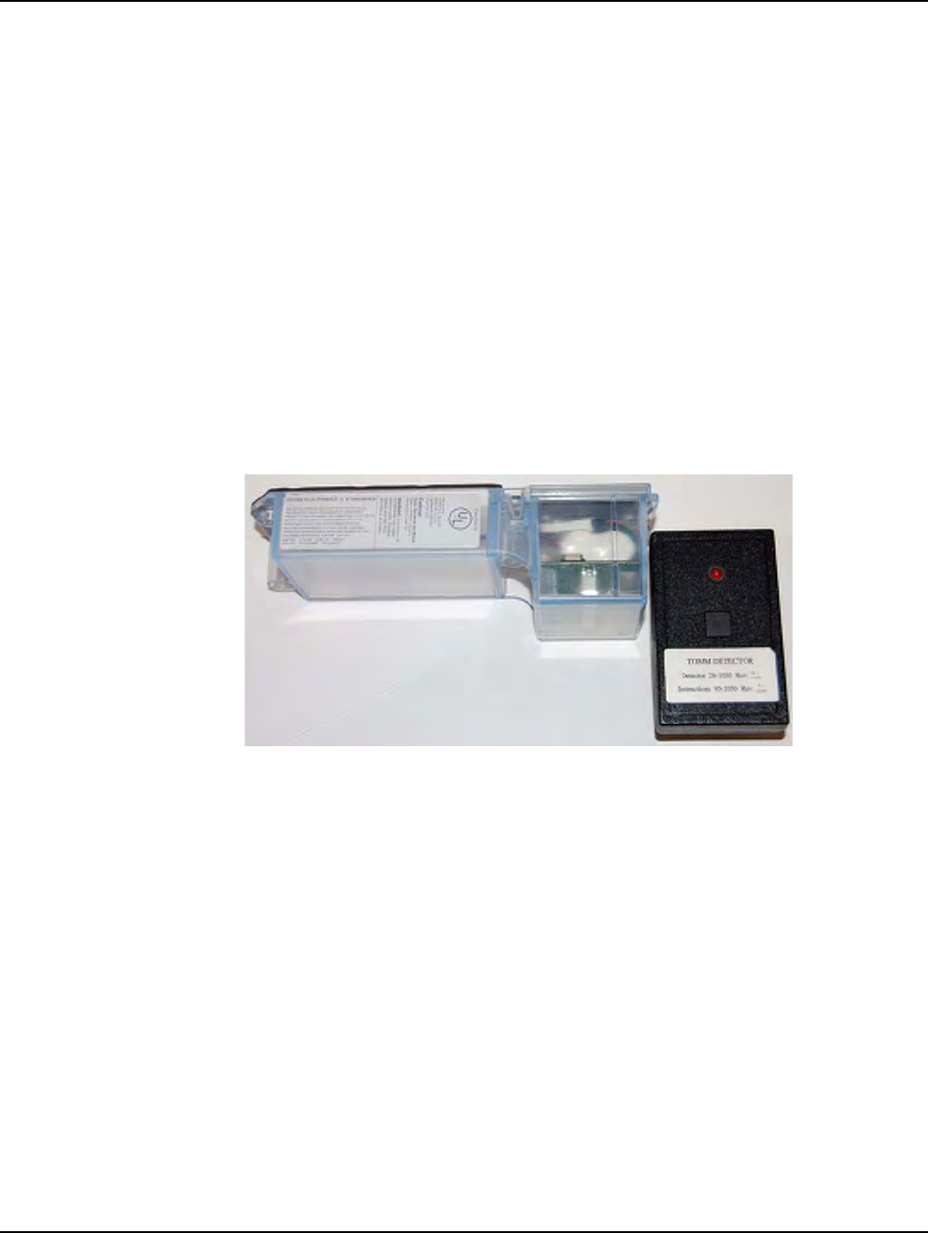
Appendix B - Using the RF Buster Landis+Gyr
86 98-3107 Rev AA One-way Gas Module Installation Guide
Residential Meter Modules
1Withthelightfacingyou,pressthebuttononthelowerendoftheRFBuster.
2PlacethecorneroftheRFBustercontainingthemagnetbythelocationofthereedswitchonthe
MeterModule.
3Continuetopressthebutton.HoldtheRFBusterwithinaboutsixinchesofthemeter.The
magnettriggerstenRFtransmissionsfromthegasmodule,witheachtransmissionseparatedby
onesecond.TheRFBusterLEDlightsandtheinternalspeakersoundsabout½secondforeach
transmissiondetected.
If the RF Buster does not detect a transmission from the module, remove the four cover screws and
place the RF Buster in the proper location. While pressing the Push Button, pull the cover off the
module.
• If the module is functional, it transmits.
If the RF Buster does not respond, consider the module defective and follow the appropriate
procedure
.
Figure B - 1. Proper Placement of the RF Buster

Landis+Gyr Appendix B - Using the RF Buster
One-way Gas Module Installation Guide 98-3107 Rev AA 87
Notes:
88 One-way Gas Module Installation Guide
Using the RF Buster
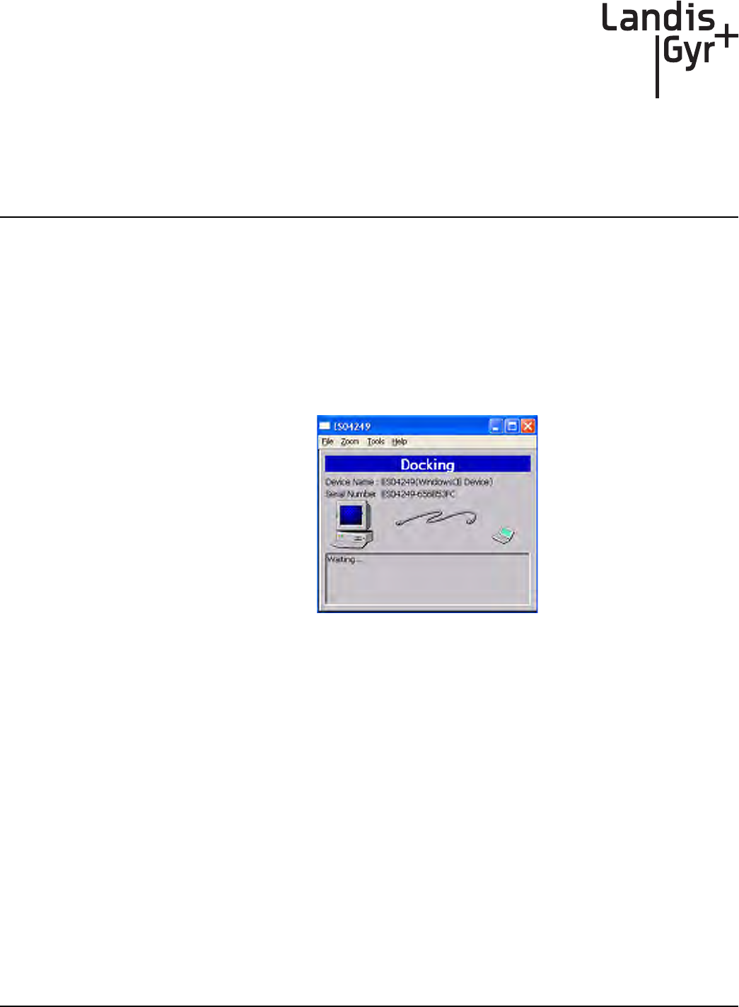
C
One-way Gas Module Installation Guide 98-3107 Rev AA 89
End of Day Handheld
Instructions
This Appendix provides detailed instructions on docking the Handheld, power requirements, and
how to change the Handheld ID. This information should only be used by experienced users.
Docking the Handheld
At the end of the day (and at other times for various reasons), dock the Handheld to upload meter
installation data and plug it in to recharge the battery.
1SelectDOCKfromthefunctionsscreen.
Figure C-1. Handheld after Dock has been selected
2 Followinstructionsonthescreen.
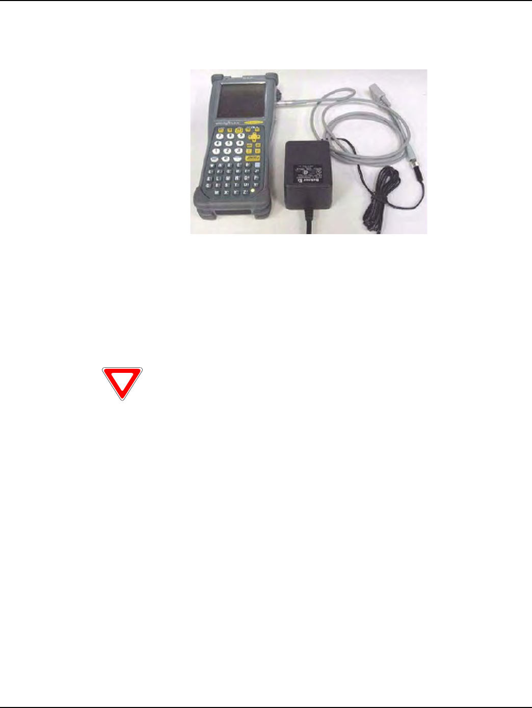
Appendix C - End of Day Handheld Instructions Landis+Gyr
90 98-3107 Rev AA One-way Gas Module Installation Guide
3Afterdatahasbeenuploaded,plugHandheldintochargingcable.
Figure C-2. Handheld DAP charging
Power Requirements
Never allow the battery to die completely. Although the route data saves to the flash memory card,
there is no EPROM memory in the Handheld. You will have to reload the code and re-calibrate the
battery.
Rebooting
There are three ways to reboot the Handheld:
1PresstheF1,9,and0simultaneouslyforapproximatelyfiveseconds.
2Pressthefollowingkeysblue,CTL,ALT,blue,DEL.
3Exittheapplication(FromtheFunctionsscreenselectDock,donotplaceincradleorpluginas
requested.PresstheshiftkeyfollowedbyF5).Type“C:”thenpressENTER.Type“reset”then
pressENTER.
Do not remove the battery. The batteries are not made to be replaced as with the other
Handhelds.

Landis+Gyr Appendix C - End of Day Handheld Instructions
One-way Gas Module Installation Guide 98-3107 Rev AA 91
How To Change The Handheld ID
Occasionally the Handheld ID may be entered incorrectly or the wrong Handheld ID may be in a
Handheld because of a memory card exchange. This section tells how to change the Handheld ID to
the correct number.
1PlacetheHandheldinthecradleanddockit.
2OpenupthemostrecentversionofHandheldEdit.
3Select“Communication”then“TransferFiles”fromthemenuonHandheldEdit.
4Ontherightsideofthepopupwindow,doubleclickonthe[CELLNET]folder.
5SelectUnitinfo.datanddeleteit.Select“Yes”toverifythatyouwanttodeletethefile.
6Select“OK”onthepopupwindowandcloseHandheldEdit.
7TheHandheldwillthenpromptyoutoenterthelast4digitsoftheserialnumberonthebackof
theHandheld.
8BeforeusingtheHandheld,makesuretheproperrouteinformationisloadedintothe
Handheld.
Known Common Problems
• If the Handheld gets jarred, the memory card may become dislodged slightly. This makes it look
like all of the data has been lost- but it is still there. Unscrew the two screws at the top of the
Handheld below the Infra-red scanner. Re-seat the card and re-tighten the cover. You may need
to re-boot the Handheld.
• If the blue key and then one of the arrow keys is pushed, part of the screen seems to disappear.
The screen was designed to hold more data. Blue key + arrow is how you shift the screen to view
that data. Push the blue button and the arrow key in the opposite direction of the screen shift.
Notes:
92 One-way Gas Module Installation Guide
End of Day Handheld Instructions

One-way Gas Module Installation Guide 98-3107 Rev AA 93
AMR AutomatedMeterReading.Energyusedatagatheringfromutility
metersbyanymeansotherthanwalkinguptothemeter,lookingatthe
dials,andrecordingthemeterreadforbilling.
C.F.H. Cubicfeetperhour
DESServer DataExchangeServer
GPrep ʺGasPrepʺAsoftwareprogramthatenablestheusertoprogram,
reprogram,inspect,read,anddispositiontoscrapanL+GgasorCPR
watermodule.
Handheld Asmallportablecomputerheldinthehand,usedtomanagedatafor
fieldinstallationofmetersandmodulesandtheprimarymeansof
dispatchingmeter‐installworkordersduringtheendpointdeployment
phase.
IDs Utility‐issuedidentificationtodenoteanindividualasanofficial
Installerfortheutility.
LAN LocalAreaNetwork:themostbasiclevelofthenetwork.TheLANisthe
constellationofendpoints,collectors,andconcentratorsthatfeeddata
upthroughthenetwork.
LP LoadProfile:methodofobtainingausagepattern,overaspanoftime,
foranemergencycustomer,typicallybasedonintervalsof15,30,or60
minutes.
MRB ʺMaterialRepairBoardʺProcessofremovingmodulesfromthefield.
OCDB OperationsCenterDataBase.EndpointManagementsystemthatreports
tonetwork,exchangesinformationwiththeutilityandRIMS.
PersonalProtectiveEquipment PersonalProtectiveEquipment,allnecessaryequipmentusedforthe
safetyoftheinstallerwhileperformingworkonmeteringequipmentas
definedinthismanual.
PSR Packetsuccessrate:Numberofgooddatapacketsreceivedpertotal
numberofpacketssent,expressedasapercentage.
RIMS RetrofitInformationManagementSystem,anOracleprogram
managingtheshopfloorassemblyandprogrammingofmodules,also
standsformyriadofdatatables.ExchangesinformationwithOCDB.
GLOSSARY
Notes:
94 One-way Gas Module Installation Guide
Glossary
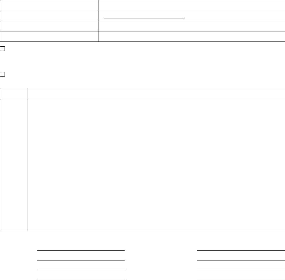
Reader’s Comment Form
AmericanResidentialMeterOne‐WayGasModuleInstallationGuide(98‐3107Rev
AA)
Pleaseusethisformonlytoidentifypublicationerrorsortorequestchangesinpublications.Your
commentsassistusinimprovingourpublications.Directanyrequestsforadditionalpublications,
technicalquestionsaboutsystems,changesinsupport,andsoon,toyourLandis+Gyrsalesrepresentative.
Youmustusethisformtocommunicateyourcommentsaboutthispublication,itsorganization,orsubject
matter,withtheunderstandingthatwemayuseordistributewhateverinformationyousupplyinany
waywebelieveappropriatewithoutincurringanyobligationtoyou.
Youcansendcommentsviaemail,conventionalmail,orfax.
Ifyourcommentdoesnotneedareply(forexample,pointingoutatypingerror),checkthisboxand
donotincludeyournameandaddressbelow.Ifyourcommentisapplicable,wewillincludeitinthe
nextrevisionofthemanual.
Ifyouwouldlikeareply,checkthisbox.Pleaseprintyournameandaddressbelow.
(Pleaseprint.)
To send your comments via... Use this contact information...
bã~áä =ëçäìíáçåëìééçêíKå~]ä~åÇáëÖóêKÅçã
`çåîÉåíáçå~ä=ã~áä i~åÇáëHdóêI=PMMMM=jáää=`êÉÉâ=^îÉKI=pìáíÉ=NMMI=^äéÜ~êÉíí~I=d^=PMMOO
c~ñ ESTUF=ORUJNRRM
Page Comments
Date CompanyName
YourName MailingAddress
PhoneNo.
Email

cçäÇ=eÉêÉ
cçäÇ=eÉêÉ
Landis+Gyr
Attn.:MarketingCommunications
30000MillCreekAve.
Suite100
Alpharetta,GA30022