Landis Gyr Technology IWRS5 Gridstream Series-5 IWR User Manual 12 0336 Exhibit Cover
Landis+Gyr Technology, Inc. Gridstream Series-5 IWR 12 0336 Exhibit Cover
Manual

5015 B.U. Bowman Drive Buford, GA 30518 USA Voice: 770-831-8048 Fax: 770-831-8598
Certification Exhibit
FCC ID: R7PIWRS5
IC: 5294A-IWRS5
FCC Rule Part: 15.247
IC Radio Standards Specification: RSS-210
ACS Project Number: 12-0336
Manufacturer: Landis+Gyr Technology, Inc.
Model: Gridstream Series-5 IWR
Manual

LANDIS+GYR CONFIDENTIAL INFORMATION
Landis+Gyr
Gridstream Series-5 IWR
Data Sheet
Publication: 98-1297 Rev AA
DRAFT 01/10/2013

Limitation on Warranties and Liability
Information in this document is subject to change without notice. This manual or any part of it thereof may not be re-
produced in any form unless permitted by contract or by written permission of Landis+Gyr.
In no event will Landis+Gyr be liable for any incidental, indirect, special, or consequential damages (including lost prof-
its) arising out of or relating to this publication or the information contained in it, even if Landis+Gyr has been advised,
knew, or should have known of the possibility of such damages.
© 201# Landis+Gyr, Inc. All Rights Reserved
Landis+Gyr Gridstream Series-5 IWR Data Sheet
Publication: 98-1297 Rev AA
Revision History
Modification Date Revision Description Author
01/10/2013 AA Work in progress Kim Utesch
Landis+Gyr
6436 County Road 11
Pequot Lakes, MN 56472
Website: www.landisgyr.com
E-mail: solutionsupport.na@landisgyr.com
Technical Support: 1-888-390-5733
© 2013 Landis+Gyr
All rights reserved.
DRAFT 01/10/2013
Data Sheet 98-1297 Rev AA 3
Landis+Gyr
Gridstream Series-5 IWR
Data Sheet
General
The Landis+Gyr Gridstream Series-5 IWR provides a basis for a powerful RF wireless mesh network
for remote data collection and end device monitoring and control. The radio provides full two-way
peer-to-peer communication to all devices within the network. The IWR also offers advanced func-
tionality, such as individual message prioritization, additional memory for localized intelligence, and
a programming language Device Control Word (DCW) used to provide interface and control to dis-
tributed automation equipment.
The IWR has one RS-232 serial port for the LAN Packet Port (LPP) and one RS-232/485 serial port
for the Transparent Packet Port (TPP). The LAN Packet Protocol Port is used to communicate to de-
vices that use the Gridstream IWR LAN Packet Protocol, such as a PC with configuration or diagnos-
tic software. The Transparent Packet Port is a general-purpose data port that is used to transport byte-
oriented data, such as DNP 3.0, Modbus, or DF1.
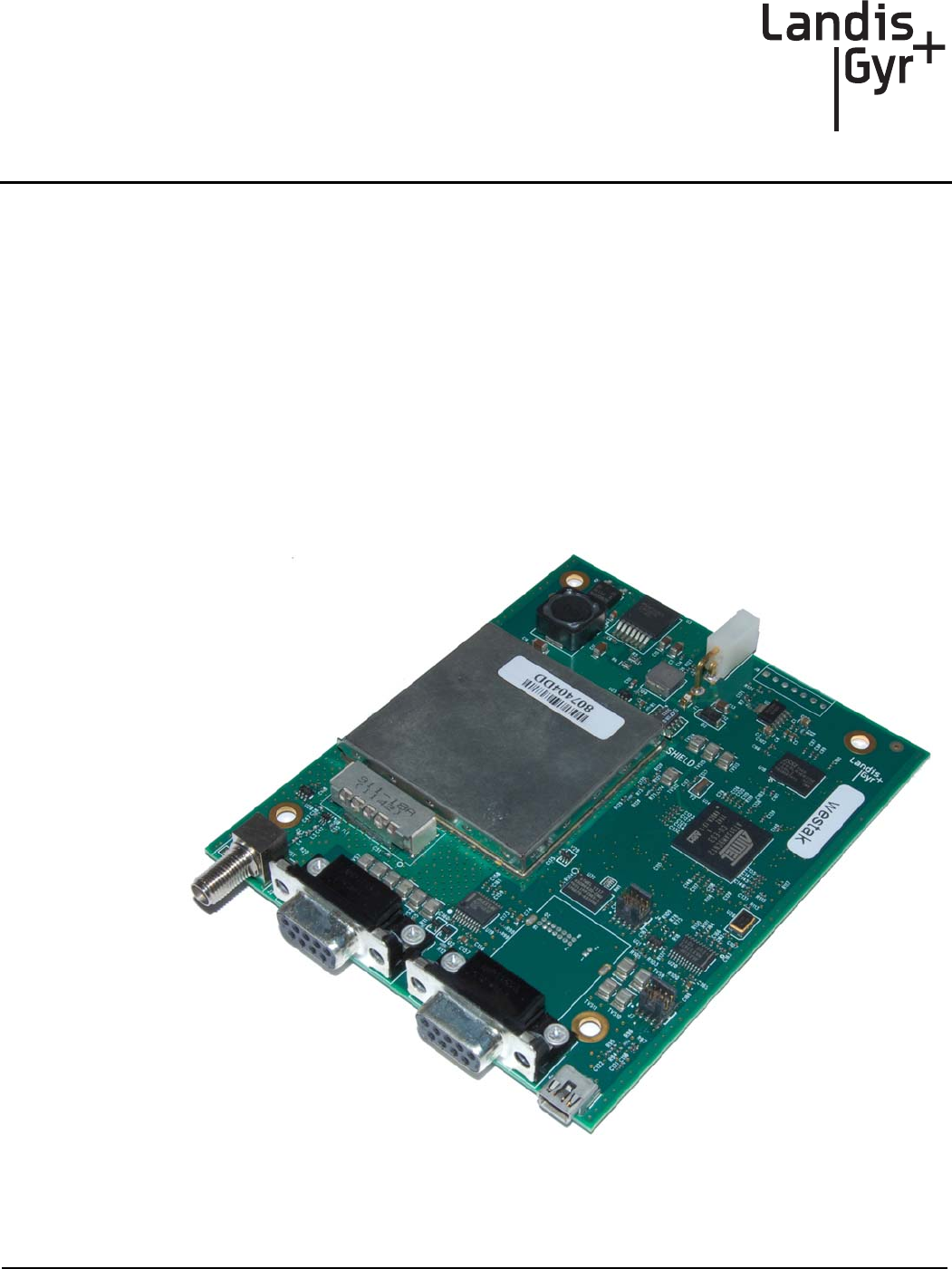
Figure 1. Landis+Gyr Gridstream Series-5 IWR
DRAFT 01/10/2013

Landis+Gyr Gridstream Series-5 IWR Data Sheet Landis+Gyr
4 98-1297 Rev AA Data Sheet
IWR Usage
The IWR was engineered specifically for varied needs of residential and commercial applications. It
enables access to the RF mesh network using a standard RS-232 connection.
Useful features of the IWR include:
•User-friendly interface via RadioShop for configuring the IWR. The interface provides:
•Current status information
•Logical configurations for:
•LPP port
•TPP port
•Simultaneous connections per RS-232 interface by:
•LPP applications
•TPP applications
FCC and Industry Canada Compliance
FCC Class B
This device complies with Part 15 of the FCC rules. Operation is subject to the following two condi-
tions:
1. This device may not cause harmful interference, and
2. This device must accept any interference received, including interference that may cause
undesired operation.
This equipment has been tested and found to comply with the limits for a Class B digital device, pur-
suant to Part 15 of the FCC Rules. These limits are designed to provide reasonable protection against
harmful interference in a residential installation. This equipment generates, uses, and can radiate radio
frequency energy and, if not installed and used in accordance with the Instructions, may cause harmful
interference to radio communications. However, there is no guarantee that interference will not occur
in a particular installation. If this equipment does cause harmful interference to radio or television re-
ception, which can be determined by turning the equipment off and on, the user is encouraged to try
to correct the interference by one or more of the following measures:
•Reorient or relocate the receiving antenna.
•Increase the separation between the equipment and receiver.
•Consult Landis+Gyr or an experienced radio technician for help
UWARNING: Changes or modifications to this device not expressly approved by Landis+Gyr
could void the user’s authority to operate the equipment.
DRAFT 01/10/2013

Landis+Gyr Landis+Gyr Gridstream Series-5 IWR Data Sheet
Data Sheet 98-1297 Rev AA 5
RF Exposure
This equipment complies with FCC radiation exposure limits set forth for an uncontrolled
environment. This equipment should be installed and operated with minimum distance of 22 cm
between the radiator and your body. This transmitter must not be co-located or operating in
conjunction with any other antenna or transmitter.
Industry Canada
This device complies with Industry Canada license-exempt RSS standard(s). Operation is subject to
the following two conditions: (1) this device may not cause interference, and (2) this device must
accept any interference, including interference that may cause undesired operation of the device.
Under Industry Canada regulations, this radio transmitter may only operate using an antenna of a
type and maximum (or lesser) gain approved for the transmitter by Industry Canada. To reduce
potential radio interference to other users, the antenna type and its gain should be so chosen that the
equivalent isotropically radiated power (e.i.r.p.) is not more than that necessary for successful
communication.
This radio transmitter (5294A-IWRS5) has been approved by Industry Canada to operate with the
antenna types listed below with the maximum permissible gain and required antenna impedance for
each antenna type indicated. Antenna types not included in this list, having a gain greater than the
maximum gain indicated for that type, are strictly prohibited for use with this device.
Approved Antenna: Omni-directional antenna, 5.5 dBi gain, 902-928 MHz, antenna impedance is 50
ohms.
Le présent appareil est conforme aux CNR d'Industrie Canada applicables aux appareils radio
exempts de licence. L'exploitation est autorisée aux deux conditions suivantes : (1) l'appareil ne doit
pas produire de brouillage, et (2) l'utilisateur de l'appareil doit accepter tout brouillage
radioélectrique subi, même si le brouillage est susceptible d'en compromettre le fonctionnement.
Conformément à la réglementation d'Industrie Canada, le présent émetteur radio peut fonctionner
avec une antenne d'un type et d'un gain maximal (ou inférieur) approuvé pour l'émetteur par Industrie
Canada. Dans le but de réduire les risques de brouillage radioélectrique à l'intention des autres utili-
sateurs, il faut choisir le type d'antenne et son gain de sorte que la puissance isotrope rayonnée équiv-
alente (p.i.r.e.) ne dépasse pas l'intensité nécessaire à l'établissement d'une communication
satisfaisante.
Le présent émetteur radio (5294A-IWRS5) a été approuvé par Industrie Canada pour fonctionner
avec les types d'antenne énumérés ci-dessous et ayant un gain admissible maximal et l'impédance
requise pour chaque type d'antenne. Les types d'antenne non inclus dans cette liste, ou dont le gain
est supérieur au gain maximal indiqué, sont strictement interdits pour l'exploitation de l'émetteur.
Host FCC Label Requirement
In the final installation, the following information must be visible:
•Contains FCC ID: R7PIWRS5
•Contains IC: 5294A-IWRS5
•Module Model: Gridstream Series-5 IWR
DRAFT 01/10/2013

Landis+Gyr Gridstream Series-5 IWR Data Sheet Landis+Gyr
6 98-1297 Rev AA Data Sheet
This device complies with Part 15 of the FCC rules. Operation is subject to the following two
conditions:
(1) This device may not cause harmful interference, and
(2) This device must accept any interference received, including interference that may cause
undesired operation.
Gridstream Series-5 IWR Specifications
Table 1. General Series-5 IWR Specifications
Electrical (General)
Input Voltage Range 6 - 28 VDC
Input Current (in transmitting mode) 320 mA typical (12 VDC operation)
Input Current (in receiving mode) 38 mA typical (12 VDC operation)
RF Frequency Range 902-928 MHz
Channel Spacing 100 or 300 kHz depending on the mode
RF Data Rate 9.6-115.2 Kbps
Receiver
Sensitivity (at 10% packet error rate) -112 dBm (9.6 Kbps) Typical / -101 dBm (115.2
Kbps) Typical
Co-channel rejection 10 dB Typical
Adjacent Channel Rejection 30 dB Typical
Alternate Channel Rejection 45 dB Typical
Transmitter
Output Power (at Antenna Connector) 21/25/30 dBm (user selectable)
Modulation Type 2-FSK, GFSK
Modulation Index 1
Out-of-band Spurious Emissions <-70 dBc
DRAFT 01/10/2013