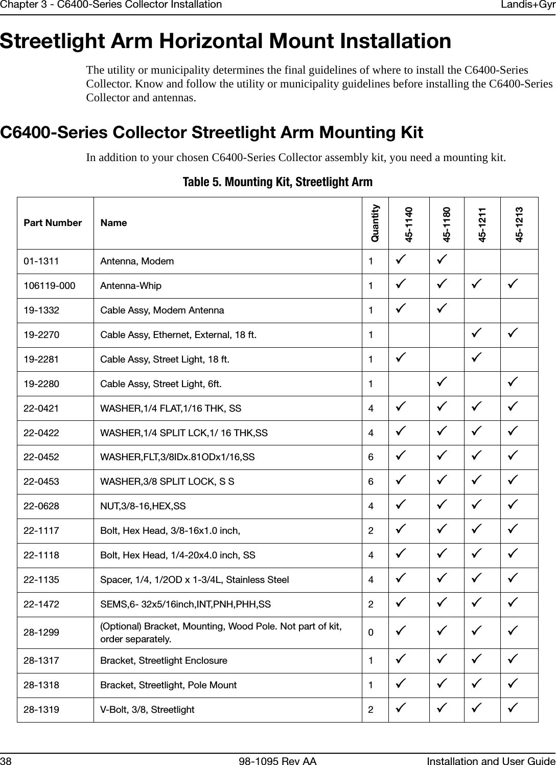
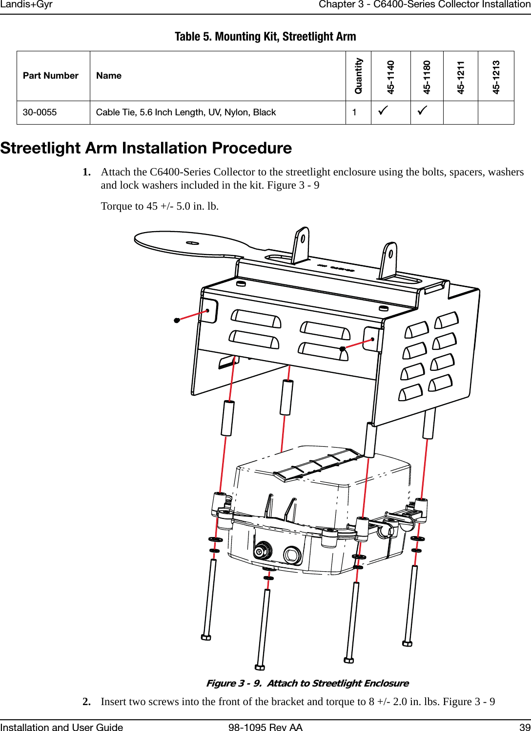
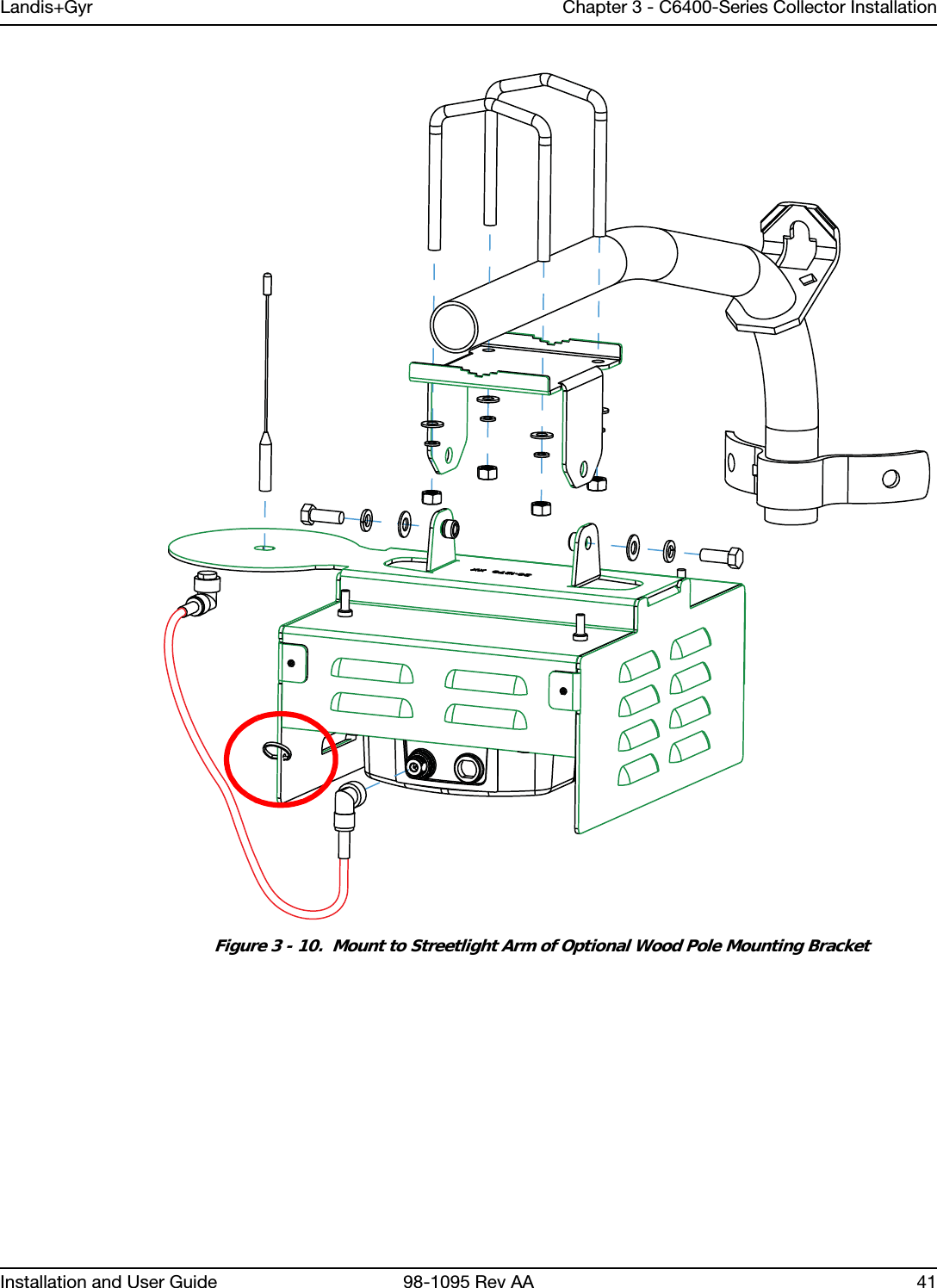
Landis Gyr Technology NG6R1S1 C6400-Series Collector User Manual 11 0082 Exhibit Cover

Landis+Gyr Technology, Inc. C6400-Series Collector 11 0082 Exhibit Cover

Manual

    5015 B.U. Bowman Drive  Buford, GA 30518 USA Voice: 770-831-8048 Fax: 770-831-8598   Certification Exhibit     FCC ID:  R7PNG6R1S1 IC: 5294A-NG6R1S1  FCC Rule Part: 15.247 IC Radio Standards Specification: RSS-210  ACS Project Number:  11-0082   Manufacturer: Cellnet Technology, Inc. Model: Collector C6400, Collector C6420, Collector C6430     Manual
LANDIS+GYR CONFIDENTIAL INFORMATIONC6400-Series CollectorInstallation andUser GuidePublication: 98-1095 Rev AA
Limitation on Warranties and LiabilityInformation in this document is subject to change without notice. This manual or any part of it thereof may not be re-produced in any form unless permitted by contract or by written permission of Landis+Gyr.In no event will Landis+Gyr be liable for any incidental, indirect, special, or consequential damages (including lost prof-its) arising out of or relating to this publication or the information contained in it, even if Landis+Gyr has been advised, knew, or should have known of the possibility of such damages.© 2011 Landis+Gyr, Inc. All Rights ReservedC6400-Series Collector Installation and User GuidePublication: 98-1095 Rev AARevision HistoryModification Date Revision Description Author11/18/2011 AA Final Review Kim UteschLandis+Gyr6436 County Road 11Pequot Lakes, MN 56472Website: www.landisgyr.comE-mail: solutionsupport.na@landisgyr.comTechnical Support: 1-888-390-5733© 2011 Landis+GyrAll rights reserved.
Installation and User Guide 98-1095 Rev AA 3Table of ContentsChapter 1:  Introduction and Overview  . . . . . . . . . . . . . . . . . . . . . . . . . . . . . . . . . . . . . . . . . . . . . . . . . .  5Overview . . . . . . . . . . . . . . . . . . . . . . . . . . . . . . . . . . . . . . . . . . . . . . . . . . . . . . . . . . . . . . . . . . . . . . . . . . . . . . . 5FCC Compliance Information . . . . . . . . . . . . . . . . . . . . . . . . . . . . . . . . . . . . . . . . . . . . . . . . . . . . . . . . . . . . . . . 6FCC Class B . . . . . . . . . . . . . . . . . . . . . . . . . . . . . . . . . . . . . . . . . . . . . . . . . . . . . . . . . . . . . . . . . . . . . . 6C6400-Series Collector FCC ID Label  . . . . . . . . . . . . . . . . . . . . . . . . . . . . . . . . . . . . . . . . . . . . . . . . . 6RF Exposure   . . . . . . . . . . . . . . . . . . . . . . . . . . . . . . . . . . . . . . . . . . . . . . . . . . . . . . . . . . . . . . . . . . . . . 6De Facto EIRP Limit  . . . . . . . . . . . . . . . . . . . . . . . . . . . . . . . . . . . . . . . . . . . . . . . . . . . . . . . . . . . . . . . 6Industry Canada  . . . . . . . . . . . . . . . . . . . . . . . . . . . . . . . . . . . . . . . . . . . . . . . . . . . . . . . . . . . . . . . . . . . 7Chapter 2:  Backhaul Configuration   . . . . . . . . . . . . . . . . . . . . . . . . . . . . . . . . . . . . . . . . . . . . . . . . . . . .  9SIM Card Installation for the C6420 Collector . . . . . . . . . . . . . . . . . . . . . . . . . . . . . . . . . . . . . . . . . . . . . . . . . . 9ESD Precautions  . . . . . . . . . . . . . . . . . . . . . . . . . . . . . . . . . . . . . . . . . . . . . . . . . . . . . . . . . . . . . . . . . . . . . . . . . 9Required Tools for SIM Card Installation and Activation  . . . . . . . . . . . . . . . . . . . . . . . . . . . . . . . . . . . . . . . . 10Installation, Replacement or Removal of a SIM Card  . . . . . . . . . . . . . . . . . . . . . . . . . . . . . . . . . . . . . . . . . . . 10Prior to Installation . . . . . . . . . . . . . . . . . . . . . . . . . . . . . . . . . . . . . . . . . . . . . . . . . . . . . . . . . . . . . . . . 10Installation Procedure   . . . . . . . . . . . . . . . . . . . . . . . . . . . . . . . . . . . . . . . . . . . . . . . . . . . . . . . . . . . . . 10Backhaul Configuration   . . . . . . . . . . . . . . . . . . . . . . . . . . . . . . . . . . . . . . . . . . . . . . . . . . . . . . . . . . . . . . . . . . 14Modem Setup for C6420 and C6430 Collectors  . . . . . . . . . . . . . . . . . . . . . . . . . . . . . . . . . . . . . . . . . 14Modem Setup Overview  . . . . . . . . . . . . . . . . . . . . . . . . . . . . . . . . . . . . . . . . . . . . . . . . . . . .   14Ethernet Setup for C6400 Collectors   . . . . . . . . . . . . . . . . . . . . . . . . . . . . . . . . . . . . . . . . . . . . . . . . . . . . . . . . 25Chapter 3:  C6400-Series Collector Installation  . . . . . . . . . . . . . . . . . . . . . . . . . . . . . . . . . . . . . . . . . .  27Pre-Installation Overview  . . . . . . . . . . . . . . . . . . . . . . . . . . . . . . . . . . . . . . . . . . . . . . . . . . . . . . . . . . . . . . . . . 27Safety Overview  . . . . . . . . . . . . . . . . . . . . . . . . . . . . . . . . . . . . . . . . . . . . . . . . . . . . . . . . . . . . . . . . . . . . . . . . 27Pre-Installation Checklist  . . . . . . . . . . . . . . . . . . . . . . . . . . . . . . . . . . . . . . . . . . . . . . . . . . . . . . . . . . . . . . . . . 27Getting Organized . . . . . . . . . . . . . . . . . . . . . . . . . . . . . . . . . . . . . . . . . . . . . . . . . . . . . . . . . . . . . . . . . . . . . . . 28C6400-Series Collector Installation Tool List  . . . . . . . . . . . . . . . . . . . . . . . . . . . . . . . . . . . . . . . . . . . 28Additional Tools Required for Metal Pole Installations  . . . . . . . . . . . . . . . . . . . . . . . . . . . . . . . . . . . 28Additional Tools Required for Building and Structure Installs . . . . . . . . . . . . . . . . . . . . . . . . . . . . . . 29Installation Material and Third Party Supplies  . . . . . . . . . . . . . . . . . . . . . . . . . . . . . . . . . . . . . . . . . . 29Antenna Mounting  . . . . . . . . . . . . . . . . . . . . . . . . . . . . . . . . . . . . . . . . . . . . . . . . . . . . . . . . . . . . . . . . 29For All Installations . . . . . . . . . . . . . . . . . . . . . . . . . . . . . . . . . . . . . . . . . . . . . . . . . . . . . . . . . . . . . . . . . . . . . . 29C6400-Series Collector Installation Sheet . . . . . . . . . . . . . . . . . . . . . . . . . . . . . . . . . . . . . . . . . . . . . . 29Power Requirements   . . . . . . . . . . . . . . . . . . . . . . . . . . . . . . . . . . . . . . . . . . . . . . . . . . . . . . . . . . . . . . 30Power Cable Preparation  . . . . . . . . . . . . . . . . . . . . . . . . . . . . . . . . . . . . . . . . . . . . . . . . . . . . . . . . . . . 30Adding Drip Loops to Cables   . . . . . . . . . . . . . . . . . . . . . . . . . . . . . . . . . . . . . . . . . . . . . . . . . . . . . . . 30Kit Part Numbers  . . . . . . . . . . . . . . . . . . . . . . . . . . . . . . . . . . . . . . . . . . . . . . . . . . . . . . . . . . . . . . . . . 31C6400-Series Collector Assembly . . . . . . . . . . . . . . . . . . . . . . . . . . . . . . . . . . . . . . . . . . . . . . . . . . . . 31Optional Parts. . . . . . . . . . . . . . . . . . . . . . . . . . . . . . . . . . . . . . . . . . . . . . . . . . . . . . . . . . . . .   31Utility Pole Mount Installation  . . . . . . . . . . . . . . . . . . . . . . . . . . . . . . . . . . . . . . . . . . . . . . . . . . . . . . . . . . . . . 31Utility Pole Mounting Kit   . . . . . . . . . . . . . . . . . . . . . . . . . . . . . . . . . . . . . . . . . . . . . . . . . . . . . . . . . . 32Utility Pole Installation Procedure . . . . . . . . . . . . . . . . . . . . . . . . . . . . . . . . . . . . . . . . . . . . . . . . . . . . 32Streetlight Arm Horizontal Mount Installation . . . . . . . . . . . . . . . . . . . . . . . . . . . . . . . . . . . . . . . . . . . . . . . . . 38C6400-Series Collector Streetlight Arm Mounting Kit . . . . . . . . . . . . . . . . . . . . . . . . . . . . . . . . . . . . 38Streetlight Arm Installation Procedure   . . . . . . . . . . . . . . . . . . . . . . . . . . . . . . . . . . . . . . . . . . . . . . . . 39
Table of Contents Landis+Gyr4 98-1095 Rev AA Installation and User GuideChapter 4:  Setting Up and Managing in Command Center  . . . . . . . . . . . . . . . . . . . . . . . . . . . . . . . . . .43Command Center Setup . . . . . . . . . . . . . . . . . . . . . . . . . . . . . . . . . . . . . . . . . . . . . . . . . . . . . . . . . . . . . . . . . . .43C6400-Series Collector Communication  . . . . . . . . . . . . . . . . . . . . . . . . . . . . . . . . . . . . . . . . . . . . . . .43Collector Auto-registration  . . . . . . . . . . . . . . . . . . . . . . . . . . . . . . . . . . . . . . . . . . . . . . . . . . . . . . . . . . . . . . . .43C6400-Series Collector General Settings Tab . . . . . . . . . . . . . . . . . . . . . . . . . . . . . . . . . . . . . . . . . . . . . . . . . .47Collector Manage Tab  . . . . . . . . . . . . . . . . . . . . . . . . . . . . . . . . . . . . . . . . . . . . . . . . . . . . . . . . . . . . . . . . . . . .48Collector Commands  . . . . . . . . . . . . . . . . . . . . . . . . . . . . . . . . . . . . . . . . . . . . . . . . . . . . . . . . . . . . . .49Statistics Tab  . . . . . . . . . . . . . . . . . . . . . . . . . . . . . . . . . . . . . . . . . . . . . . . . . . . . . . . . . . . . . . . . . . . . . . . . . . .50History Tab  . . . . . . . . . . . . . . . . . . . . . . . . . . . . . . . . . . . . . . . . . . . . . . . . . . . . . . . . . . . . . . . . . . . . . . . . . . . .52Chapter 5:  Using Endpoint Testing Manager  . . . . . . . . . . . . . . . . . . . . . . . . . . . . . . . . . . . . . . . . . . . . .53Access to Endpoint Test Manager . . . . . . . . . . . . . . . . . . . . . . . . . . . . . . . . . . . . . . . . . . . . . . . . . . . . . . . . . . .53Connecting to a C6400-Series Collector  . . . . . . . . . . . . . . . . . . . . . . . . . . . . . . . . . . . . . . . . . . . . . . . . . . . . . .53Collector Tab . . . . . . . . . . . . . . . . . . . . . . . . . . . . . . . . . . . . . . . . . . . . . . . . . . . . . . . . . . . . . . . . . . . . . . . . . . .53Collector Tab - Identification sub-tab   . . . . . . . . . . . . . . . . . . . . . . . . . . . . . . . . . . . . . . . . . . . . . . . . .55Collector Tab - Basic Configuration sub-tab  . . . . . . . . . . . . . . . . . . . . . . . . . . . . . . . . . . . . . . . . . . . .56Collector Tab - Client Routing sub-tab   . . . . . . . . . . . . . . . . . . . . . . . . . . . . . . . . . . . . . . . . . . . . . . . .58Collector Tab - Events/Alerts sub-tab   . . . . . . . . . . . . . . . . . . . . . . . . . . . . . . . . . . . . . . . . . . . . . . . . .59Statistics sub-tab . . . . . . . . . . . . . . . . . . . . . . . . . . . . . . . . . . . . . . . . . . . . . . . . . . . . . . . . . . . . . . . . . .60Appendix A:  Specifications . . . . . . . . . . . . . . . . . . . . . . . . . . . . . . . . . . . . . . . . . . . . . . . . . . . . . . . . . . .61Specifications . . . . . . . . . . . . . . . . . . . . . . . . . . . . . . . . . . . . . . . . . . . . . . . . . . . . . . . . . . . . . . . . . . . . . . . . . . .61C6400-Series Collector Dimensions  . . . . . . . . . . . . . . . . . . . . . . . . . . . . . . . . . . . . . . . . . . . . . . . . . . . . . . . . .63Appendix B:  Cable Installation  . . . . . . . . . . . . . . . . . . . . . . . . . . . . . . . . . . . . . . . . . . . . . . . . . . . . . . . .65Power Connection and Termination  . . . . . . . . . . . . . . . . . . . . . . . . . . . . . . . . . . . . . . . . . . . . . . . . . . . . . . . . .65Junction/Disconnect Box Installation . . . . . . . . . . . . . . . . . . . . . . . . . . . . . . . . . . . . . . . . . . . . . . . . . .65Direct Cable Installation to Main  . . . . . . . . . . . . . . . . . . . . . . . . . . . . . . . . . . . . . . . . . . . . . . . . . . . . .67Ethernet Cable Installation  . . . . . . . . . . . . . . . . . . . . . . . . . . . . . . . . . . . . . . . . . . . . . . . . . . . . . . . . . .68
1User and Installation Guide 98-1095 Rev AA 5Introduction and OverviewOverviewThe C6400-Series Collector is a RF mesh network device that serves a smaller number of endpoints in rural and deployment fringes.Figure 1 - 1.  C6400-Series CollectorThe C6400 Series collector is a NEMA-4 sealed enclosure with a power supply, backup battery, sys-tem processor board and hosts one Gridstream IWR radio.  The C6400 Series Collector can support IP addressability for external backhaul modems (C6400 variant) or the collector can be ordered with an integrated single backhaul modem for communication with public wireless carriers (C6420 or C6430 variants).  The C6400 Series collectors receive data from Gridstream network routers and end-points and sends the data to the host system via internet packets.  These collectors mount on a wooden utility pole or a streetlight arm.Three different C6400-Series Collector units are available:• Collector C6400. No wireless backhaul modem.• Collector C6420. Features embedded GSM/GPRS wireless backhaul modem.• Collector C6430. Features embedded CDMA/EVDO wireless backhaul modem.
Chapter 1 - Introduction and Overview Landis+Gyr6 98-1095 Rev AA User and Installation GuideFCC Compliance InformationFCC Class BThis equipment has been tested and found to comply with the limits for a Class B digital device, pur-suant to Part 15 of the FCC Rules. These limits are designed to provide reasonable protection against harmful interference in a residential installation. This equipment generates, uses, and can radiate radio frequency energy and, if not installed and used in accordance with the Instructions, may cause harmful interference to radio communications. However, there is no guarantee that interference will not occur in a particular installation. If this equipment does cause harmful interference to radio or television re-ception, which can be determined by turning the equipment off and on, the user is encouraged to try to correct the interference by one or more of the following measures: •Reorient or relocate the receiving antenna. •Increase the separation between the equipment and receiver. •Consult Landis+Gyr or an experienced radio technician for help.UWARNING: Changes or modifications to this device not expressly approved by Landis+Gyr Technology, Inc. could void the user's authority to operate the equipment.C6400-Series Collector FCC ID LabelFigure 1 - 2.  FCC/Industry Canada ID LabelRF Exposure In accordance with FCC requirements of human exposure to radio frequency fields, the radiating el-ement shall be installed such that a minimum separation distance of 22 centimeters will be main-tained. De Facto EIRP LimitThe collector meets the required FCC specifications with any customer-selectable RF power setting of the radio, using the antennas indicated in this document. FCC testing was conducted using an an-tenna with a gain of 5.5 dBi. Antennas with higher gain at higher RF power settings may result in EIRP levels in excess of the FCC limit.NOTE: If you increase the power from the factory settings, this can cause communication problemsfor other radios in the network.FCC ID: R7PNG6R1S1IC: 5294A-NG6R1S1THIS DEVICE COMPLIES WITH PART 15 OF THE FCC RULES. OPERATION IS SUBJECT TO THE FOLLOWING TWO CONDITIONS: (1) THIS DEVICE MAY NOT CAUSE HARMFUL INTERFERENCE, AND (2) THIS DEVICE MUST ACCEPT ANY INTERFERENCE RECEIVED, INCLUDING INTERFERENCE THAT MAY CAUSE UNDESIRED OPERATION.THIS PRODUCT IS PROTECTED BY ONE OR MORE OF THE FOLLOWING PATENTS: (OTHER PATENTS PENDING) 4,939,726 - 5,007,052 - 5,079,768 - 5,115,422 - 5,130,987TORQUE 1/4-20 BOLTS TO 45 LB.IN.MODEL: COLLECTOR _______ MADE IN USA900 MHz CLASS B96-277vrmsP/N _________REV: ___ MFG DATE __________
Landis+Gyr Chapter 1 - Introduction and OverviewUser and Installation Guide  98-1095 Rev AA 7Industry CanadaThe term "IC:" before the radio certification number only signifies that Industry Canada technical specifications were met.This Class B digital apparatus meets all requirements of the Canadian Interference Causing Equip-ment Regulations. Operation is subject to the following two conditions: (1) this device may not cause harmful interference, and (2) this device must accept any interference received, including interference that may cause undesired operation.Cet appareillage numérique de la classe B répond à toutes les exigences de l'interférence canadienne causant des règlements d'équipement. L'opération est sujette aux deux conditions suivantes: (1) ce dispositif peut ne pas causer l'interférence nocive, et (2) ce dispositif doit accepter n'importe quelle interférence reçue, y compris l'interférence qui peut causer l'opération peu désirée.To reduce potential radio interference to other users, the antenna type and its gain should be so chosen that the equivalent isotropically radiated power (e.i.r.p.) is not more than that permitted for successful communication.This device has been designed to operate with the antennas listed below, and having a maximum gain of 5.5 dBi. Antennas not included in this list or having a gain greater than 5.5 dBi are strictly prohib-ited for use with this device. The required antenna impedance is 50 ohms.Approved Antennas: Landis+Gyr 01-1311: Antenna, Modem; 106119-000: Antenna, Whip
Installation and User Guide 98-1095 Rev AA 92Backhaul ConfigurationSIM Card Installation for the C6420 CollectorA subscriber identification module (SIM) is a smart card that securely stores the service-subscriber key (IMSI) used to identify a subscriber on mobile telephony devices (such as mobile phones, computers and C6400-Series Collectors).Contact your local cellular carrier to obtain an Industrial Grade SIM card for each C6420 Collector to be installed. NOTE: Industrial grade SIM cards that support a temperature range of at least -40 to 85C are required for C6400-Series Collector installations.UWARNING: Do not attempt to open a C6420 Collector and install a SIM card in the field. The C6420 Collector requires SIM card installation in a meter shop environment by qualified personnel.ESD PrecautionsACAUTION: These parts are static sensitive. Prior to handling, put on a Electrostatic Discharge (ESD) wrist strap and attach it to ground.Electrostatic discharge (ESD) is the release of stored static electricity that can damage electrical circuitry. Static electricity is often stored in your body, and discharged when you come in contact with an object with a different potential. The ESD wrist strap safely channels this electricity from your body to a proper ground.Use an ESD wrist strap whenever you open a C6400-Series Collector, particularly when you will be handling SIM cards. In order to work properly, the wrist strap must make good contact at both ends (with your skin at one end, and with the ground at the other).UWARNING: The wrist strap is intended for static control only. It will not reduce or increase your risk of receiving an electric shock from electrical equipment. Follow the same precautions you would use without a wrist strap.
Chapter 2 - Backhaul Configuration Landis+Gyr10 98-1095 Rev AA Installation and User GuideRequired Tools for SIM Card Installation and ActivationThe following tools are required for SIM Card installation and activation.•Industrial grade SIM card•Torque Wrench•Endpoint Testing Manager (ETM) version 5.5.7 or later software running on an external PC or Laptop Computer•C6400-Series Collector radio antenna•External power strip connected to a 120VAC source•External AC Power cable (19-2276)Installation, Replacement or Removal of a SIM CardThe following steps are required for successful installation, replacement or removal of a SIM Card.UWARNING: The C6420 Collector can be identified by a tie-wrap around the unit when it is shipped from the factory. Cut the tie wrap and discard it before opening the unit. If there is no tie wrap, do not open the unit.Prior to Installation1. Record the SIM Card ID number located on the front of the card.Figure 2 - 1.  Front and Back of a SIM CardInstallation Procedure1. Open the C6400-Series CollectorA. Remove the 6 bolts, nuts and washers from the C6400-Series Collector enclosure.NOTE: The enclosure bolts on C6420 Collector units are hand tightened and not torqued to the required setting when shipped from the manufacturer.ID Number
Landis+Gyr Chapter 2 - Backhaul ConfigurationInstallation and User Guide 98-1095 Rev AA 11UWARNING: DO NOT DISCONNECT BATTERY PACK FROM CARRIER BOARD. The battery will not operate if is disconnected and reconnected. Figure 2 - 2.  Bolt LocationsUWARNING: Care must be taken to not disturb any other components inside the enclosure.   DO NOT UNPLUG ANY CONNECTIONS WITHIN THE ENCLOSURE. Disconnecting and reconnecting of components will cause serious communication issues. Do not allow the two sides of the enclosure to separate completely. B. Carefully open enclosure and lay flat on the work surface. •Ensure that the gasket remains on the PCB half of the enclosure. •Do not allow the two halves of the enclosure to separate completely, ensure that all connections between the two halves remain intact. •Do not unplug any components.C. Locate SIM Card slot. Remove Bolts,Nuts and Washers123456
Chapter 2 - Backhaul Configuration Landis+Gyr12 98-1095 Rev AA Installation and User GuideFigure 2 - 3.  SIM Card Location2. Install the SIM CardA. Locate the slot for the SIM card.B. Align the SIM card with the marking on the slot. The gold contacts of the SIM card face down toward the contacts of the slot.Figure 2 - 4.  Align SIM Card to SIM Card SlotC. Carefully slide SIM card in until fully inserted.GasketSIM CardSlot
Landis+Gyr Chapter 2 - Backhaul ConfigurationInstallation and User Guide 98-1095 Rev AA 13Figure 2 - 5.  SIM Card Properly Inserted3. Close the C6400-Series CollectorA. Make sure that the gasket is on the base side of the enclosure to aid in proper alignment of the top lid, see Figure 2 - 3.B. Shut lid enclosure onto base enclosure. NOTE: Ground cable and battery cable must be fully within the inside of the enclosure while it is closed.C. Replace bolts, washers and nuts, see Figure 2 - 6. To ensure a water tight seal, torque each bolt to 25 +/- 2 IN. LBS. Alternating from side to side and from top to bottom in the following sequence, 1, 4, 3, 6, 2, 5, see Figure 2 - 6. Make a second pass alternating from side to side and from top to bottom, in the same sequence, torquing each bolt to 45 +/- 5 IN. LBS.
Chapter 2 - Backhaul Configuration Landis+Gyr14 98-1095 Rev AA Installation and User GuideFigure 2 - 6.  Replace Bolts, Washers and Nuts and TightenBackhaul ConfigurationModem Setup for C6420 and C6430 CollectorsModem Setup OverviewThis Procedure requires the use of an external Gridstream RF IWR radio and Endpoint Testing Manager (ETM) version 5.5.7 or later, running on an external PC or laptop computer.•Attached both antennas to the C6400-Series Collector.•Attach antenna to the IWR.123456
Landis+Gyr Chapter 2 - Backhaul ConfigurationInstallation and User Guide 98-1095 Rev AA 15•External IWR should be powered ON when the C6400-Series Collector is powered up to allow time for radios to synchronize.•C6400-Series Collector must be within the cellular network providers service area for the activation to work correctly.•Account must be provisioned within the carrier’s cellular network in advance of activation.NOTE: C6400-Series Collectors are shipped with the default Network ID setting of 670. The external IWR radio used to communicate with the C6400-Series Collector must also be set at 670.Connect to the C6400-Series Collectors using ETMFor all modem models begin communication with the C6400-Series Collectors with the following steps. 1. Using ETM on an external PC, connect to an external IWR radio. When ETM program is started, it will require users to log in using a Command Center account.NOTE: For more information on using ETM, please see Landis+Gyr publication 98-1055: Gridstream 2-Way Endpoint Testing Manager User Guide.2. Once logged in, the ETM application connects to the previously connected serial port automatically. If it is not connecting, click on the Connection Tab and then choose the available serial port from the drop-down menu. Choose the COM port from the drop-down menu and then click on Connect. Verify Enable Field Mode in Application Settings is selected.Figure 2 - 7.  Connect to Head End3. After clicking the Connect button, the display will automatically revert to the Device Test tab. 4. Verify the Current Mode in the Mode Settings window of this tab is set to Field Mode.5. Select the Head End Radio tab and click Get WAN Nodes List. The WAN Nodes Information report will open.
Chapter 2 - Backhaul Configuration Landis+Gyr16 98-1095 Rev AA Installation and User GuideFigure 2 - 8.  Get WAN Nodes ListThe WAN Nodes list will open, see Figure 2 - 9.6. Select the radio of target C6400-Series Collector and push Test Module button located at the top of the screen.Figure 2 - 9.  WAN Nodes InformationNOTE: When the radio of the C6400-Series Collector is successfully contacted, the Collector tab will become available. If the procedure times out, press the Start Test button on the Device Test tab.C6420 Modem Setup1. (Optional Step) Attach C6400-Series Collector radio antenna.NOTE: If C6400-Series Collector is within close proximity to the IWR radio, an antenna will not be needed.2. Attach an external power strip to 120VAC source - set the switch on the power strip to the OFF position.3. Attach the external AC Power cable (19-2276) to the 7 pin Male AC socket of the C6400-Series Collector enclosure and to the power strip.GSM Modem SetupThis Procedure requires the use of an external Gridstream RF IWR radio and Endpoint Testing Manager (ETM) version 5.5.7 or later, running on an external PC or laptop computer. The external
Landis+Gyr Chapter 2 - Backhaul ConfigurationInstallation and User Guide 98-1095 Rev AA 17IWR should be powered ON when the C6400-Series Collector is powered up to allow time for radios to synchronize.NOTE: C6400-Series Collectors are shipped with the default Network ID setting of 670. The external IWR radio used to communicate with the C6400-Series Collector must also be set at 670.1. Turn the power strip switch to ON.2. Note the LAN ID of the C6400-Series Collector.3. Using ETM on an external PC, connect to an external IWR radio. When ETM program is started, it will require users to log in using a Command Center account.NOTE: For more information on using ETM, please see Landis+Gyr publication 98-1055: Gridstream 2-Way Endpoint Testing Manager User Guide.
Chapter 2 - Backhaul Configuration Landis+Gyr18 98-1095 Rev AA Installation and User Guide4. Once logged in, the ETM application connects to the previously connected serial port automatically. If it is not connecting, click on the Connection Tab and then choose the available serial port from the drop-down menu. Choose the COM port from the drop-down menu and then click on Connect. Verify Enable Field Mode in application settings is selected.NOTE: Before connecting confirm that you are in Field Mode. Figure 2 - 10. 5. Choose the COM port from the drop-down menu and then click on Connect. Figure 2 - 10.Figure 2 - 10.  Connect to Head End6. After clicking the Connect button, the display will automatically revert to the Device Test tab. 7. Verify the Current Mode in the Mode Settings window of this tab is set to Field Mode.8. Select the Head End Radio tab and click Get WAN Nodes List. The WAN Nodes Information report will open.Figure 2 - 11.  Get WAN Nodes ListThe WAN Nodes list will open.9. Select the radio of target C6400-Series Collector and push Test Module button located at the top of the screen.
Landis+Gyr Chapter 2 - Backhaul ConfigurationInstallation and User Guide 98-1095 Rev AA 19Figure 2 - 12.  WAN Nodes InformationNOTE: When the radio of the C6400-Series Collector is successfully contacted, the Collector tab will become available. Figure 2 - 13.  Collector Tab10. On the Collector tab, the following Modem Settings will be populated, see Figure 2 - 13:Confirm the presence of a SIM Card by looking at the ICC ID and IMSI entries. Confirm the entries match the account. These entries should not say Check SIM.A. Modem Type: Multi TechEDGEB. Manufacturer: Modem ManufacturerC. Model: Modem model numberD. Serial Number: Modem serial numberE. Provider: Selected carrier
Chapter 2 - Backhaul Configuration Landis+Gyr20 98-1095 Rev AA Installation and User GuideF. Revision: Modem revision.G. ICC ID: SIM Card ICC IDH. IMSI: SIM Card IMSII. Status: RASCS_OpenPort, S_OK. This message confirms that the modem is currently disabled.NOTE: If any fields say Check SIM, an error has occurred in the installation of the SIM card. Contact Landis+Gyr Customer Support at 1-888-390-5733.11. Select the Settings.... button, see Figure 2 - 13. The Modem Configuration window will open.Figure 2 - 14.  Modem Configuration Window12. Modem Configuration. This procedure requires cellular service from the carrier in question.A. Enter APN information obtained from the carrier and is specific to each customer.B. Enter a User ID and Password.C. Check the Enable cellular modem check-box.D. Select Send.13. After selecting Send, select Yes to reboot the C6400-Series Collector. Wait approximately 3-5 minutes to allow the C6400-Series Collector to reboot. Once this time has elapsed, select Fetch All, see Figure 2 - 13.14. The status change to RASCS_Connected, S_OK confirms that the unit is successfully connected to the cellular network.
Landis+Gyr Chapter 2 - Backhaul ConfigurationInstallation and User Guide 98-1095 Rev AA 21Figure 2 - 15.  Modem StatusACAUTION:  If the value noted for Battery Voltage states Error, contact Landis+Gyr Technical Support at 1-888-390-5733. This condition indicates that the battery pack became disconnected or other communication issues have occurred. As a result, battery stats will display erroneous values.C6430 Verizon CDMA Modem Setup1. Complete steps 1-6 in section See “Connect to the C6400-Series Collectors using ETM”2. After connecting to the C6400-Series Collector, please confirm the Serial Number field matches the ESN on the account to be activated. Also, ensure the Provider indicates Verizon. With Verizon it is necessary to dial an activation code to the network. This will signal NAM information to be sent over the air. This can be done by pressing the Activate button.
Chapter 2 - Backhaul Configuration Landis+Gyr22 98-1095 Rev AA Installation and User GuideFigure 2 - 16.  Initiate Verizon Service3. Once the activation process has been initiated, wait at least 5 minutes for the over the air programming of the NAM to occur. Once completed, press the Settings button Figure 2 - 16. 4. The Modem Configuration information box will open.These settings are for reference only and will not be editable. Check the Enable Internet data connection for the cellular modem check-box and select Send. Figure 2 - 17.  Modem Configuration Settings5. Select Yes from the pop-up dialog box.
Landis+Gyr Chapter 2 - Backhaul ConfigurationInstallation and User Guide 98-1095 Rev AA 23Figure 2 - 18.  Enable Modem6. Wait approximately 3-5 minutes for the C6400-Series Collector to reboot. Once this time has elapsed, attempt to Fetch All again, Figure 2 - 16. The status will change to RASCS_Connected, S_OK when the unit is successfully connected to the cellular network.Figure 2 - 19.  Connected to Cellular NetworkC6430 Sprint CDMA Modem Setup1. Complete steps 1-6 in section See “Connect to the C6400-Series Collectors using ETM”2. After connecting to the C6400-Series Collector, please confirm the Serial Number field matches the ESN on the account to be activated. Click the Settings button.
Chapter 2 - Backhaul Configuration Landis+Gyr24 98-1095 Rev AA Installation and User GuideFigure 2 - 20.  Initiate Sprint Service3. The Activation Settings information box will open displaying the Modem Configuration settings, Figure 2 - 21. Enter the Mobile IP settings obtained from the cellular service provider. Check the Enable Internet data connection for the cellular modem check-box and select Send.Figure 2 - 21.  Modem Configuration Settings4. Wait approximately 3-5 minutes for the C6400-Series Collector to reboot. Once this time has elapsed, attempt to Fetch All again, Figure 2 - 16. The status will change to RASCS_Connected, S_OK when the unit is successfully connected to the cellular network.
Landis+Gyr Chapter 2 - Backhaul ConfigurationInstallation and User Guide 98-1095 Rev AA 25Figure 2 - 22.  Connected to Cellular NetworkEthernet Setup for C6400 CollectorsThe utility determines the best configuration to connect the collector to the network.
Installation and User Guide 98-1095 Rev AA 273C6400-Series Collector InstallationPre-Installation OverviewProper planning and thorough preparation are critical to successful C6400-Series Collector installation. This chapter outlines basic requirements for the pre-installation phase of the C6400-Series Collector deployment process.Safety OverviewPrior to starting the installation process, you must develop and launch an installer safety training plan for initial, refresher, and ongoing safety training. Ensure that installers receive appropriate initial and refresher training to meet their specific safety-related responsibilities. You must provide safety training when:1. an existing installer assumes new duties for which they have not previously received training.2. new processes and methodologies representing new risks are introduced into the installation environment.3. previously unidentified risks are reported.The installation supervisory team assumes responsibility for ensuring that installers are properly trained, authorized, and continually qualified to perform their work. The team must also take responsibility for the safety of their installers and to assure safe work methodologies. Installers must understand that their supervisor’s responsibility does not relieve them from their individual responsibility to perform the work safely and to follow all safety rules and procedures applicable to their work.Pre-Installation ChecklistBe prepared before you go on site. The following list includes most pre-install items.Table 1. Pre-Install ChecklistItem DescriptionSite SurveyThe utility has surveyed the area to determine optimal locations for C6400-Series Collector installation. Landis+Gyr offers this professional service as a contract option.
Chapter 3 - C6400-Series Collector Installation Landis+Gyr28 98-1095 Rev AA Installation and User GuideGetting OrganizedC6400-Series Collector Installation Tool List•Gas or hydraulic-powered drill, 3/4 inch augur bit•Two adjustable-end wrenches•Squeeze-on crimpers and crimps•Standard socket wrench set•C6400-Series Collector and applicable install kit•C6400-Series Collector power cable with standard 120VAC outlet •Survey sheet•Personal Protection Equipment•Voltmeter•Cell phone or 2-way communication device•Phillips head screw driver•Laptop computer with serial port or USB to serial adapter•IWR Radio Kit (IWR, Power Supply, Antenna, Serial Cable)Additional Tools Required for Metal Pole Installations•Steel banding tool•Tin snips•HammerObtain Necessary PermitsWhen the C6400-Series Collector is to be installed on utility or municipal property such as utility poles, there is a general agreement to install on these poles. There may be a requirement for the utility or municipality to approve individual sites. It is the installer's responsibility to ensure that approval has been given for each installation.Network Installation TimelineThe Network Installation Plan specifies and formalizes the entire C6400-Series Collector installation plan. Perform all surveys in advance to ensure ample time for make-ready work as well as addressing any unforeseen installation issues. All C6400-Series Collectors will be installed, quality-checked, and online prior to any endpoint installation in a scheduled route.Tools and Equipment The latter part of this chapter has detailed tool and equipment information.Bucket Truck Procure all necessary barricade and traffic permits for the bucket truck as required, unless covered by prior permits.Table 1. Pre-Install ChecklistItem Description
Landis+Gyr Chapter 3 - C6400-Series Collector InstallationInstallation and User Guide 98-1095 Rev AA 29Additional Tools Required for Building and Structure Installs•Steel banding tool•Hammer drill•BitsInstallation Material and Third Party SuppliesThe installation process consists of using predetermined route information identifying C6400-Series Collectors that need to be installed and methods for recording data to document the installation. From the Cross-Dock, obtain C6400-Series Collector and installation kits to install.Additional Materials that may be needed:•Steel banding material•Mastic/vinyl tape•Crimp-on connectorsNOTE: 28-1299: Bracket, Mounting, Wood Pole, is not part of a mounting kit and must be ordered separately.Antenna MountingThe C6400-Series Collector requires two antennas to communicate with the endpoints and to relay information from the endpoint to the host application:1. One modem antenna2. One whip antennaThe LAN antenna mount on the bottom of the C6400-Series Collector. The WAN communications antenna mounts on top of the enclosure or on the antenna bracket.ACAUTION: Use only Landis+Gyr-approved antennas.For All InstallationsC6400-Series Collector Installation SheetThe utility provides a C6400-Series Collector Installation Sheet for every C6400-Series Collector to be installed. The sheet contains:•Street address•Type of mounting (wood pole, streetlight pole, building, etc.)•Access method (bucket truck or installer climb).
Chapter 3 - C6400-Series Collector Installation Landis+Gyr30 98-1095 Rev AA Installation and User GuidePower RequirementsPower requirements are listed in Product Specifications. Verify that the power source is 120V-240VAC single phase.Power Cable PreparationYou can use the following AC power cable options with any Landis+Gyr mounting kits. Cable part numbers are: • 19-2207. Cable Assy, Power Cable, 10ft• 19-2286. Cable Assy, Power Cable, 20 ft• 19-2280. Cable Assy, Street Light, 6 ft• 19-2281. Cable Assy, Street Light, 18 ftDepending on the utility requirements, physically connecting to the secondary may have additional requirements. Adding Drip Loops to CablesFor any cables in an assembly, allow some slack to rest below metal parts. The slack is called a “drip loop.” With a drip loop, water from rain and condensation drips from the cable without damaging associated mechanical equipmentFigure 3 - 1.  Cable with a drip loopSee “Cable Installation” on page 65, for additional power cable installation information.
Landis+Gyr Chapter 3 - C6400-Series Collector InstallationInstallation and User Guide 98-1095 Rev AA 31Kit Part NumbersDifferent kinds of installs may require different mounting and install kits. The following table contains a list of part numbers by installation type. This document details each kit in the appropriate install description.For information about installation types not listed here, contact Landis+Gyr Customer Operations via solutionsupport.na@landisgyr.com.C6400-Series Collector AssemblyUnless otherwise noted, all kits in this manual are specifically for the C6400-Series Collector Optional PartsLandis+Gyr can accommodate specialized needs for remote antenna installation.Utility Pole Mount InstallationThe utility or municipality determines the final guidelines of where to install the C6400-Series Collector. Know and follow the utility or municipality guidelines before installing the C6400-Series Collector and antennas.Table 2. Mounting KitsKit Number Description45-1211 Collector C6400: Mounting Kit, Street Light Arm, 18 ft. Cable45-1212 Collector C6400: Mounting Kit, Utility Pole, 20 ft. Cable45-1213 Collector C6400: Mounting Kit, Street Light Arm, 6 ft. Cable45-1214 Collector C6400: Mounting Kit, Utility Pole, 6 ft. Cable45-1140  Collector C6420/C6430: Mounting Kit, Street Light Arm, 18 ft. Cable45-1180 Collector C6420/C6430: Mounting kit, Street Light Arm, 6ft. Cable45-1141 Collector C6420/C6430: Mounting Kit, Utility Pole, 20 ft. Cable45-1367 Collector C6420/C6430: Mounting kit, Utility Pole, 10ft CableTable 3. C6400-Series CollectorPart Number Name26-1330 C6400-Series Collector w/CDMA Modem - Sprint26-1331 C6400-Series Collector w/CDMA Modem - Verizon26-1398 C6400-Series Collector, w/Edge Modem26-1399 C6400-Series Collector without Modem
Chapter 3 - C6400-Series Collector Installation Landis+Gyr32 98-1095 Rev AA Installation and User GuideUtility Pole Mounting KitIn addition to the C6400-Series Collector assembly kit, you need a mounting kit.Utility Pole Installation Procedure1. Affix the Wood Pole Arm (PN 28-1368) to the wood pole using three mounting bolts (two lag bolts and one D/A bolt) with washer and nut or steel bands. (Hardware parts are not included in kit.)Table 4. Utility Pole Mounting KitPartNumber Name Qty45-114145-136745-121245-121401-1311 Antenna, Modem 1 106119-000 Antenna-Whip 1 19-1332 Cable Assy, Modem Antenna 1 19-2270 Cable Assy, Ethernet, External, 18 ft. 1 19-2286 Cable Assy, Power Cable, 20 ft. 1 19-2207 Cable Assy, Power Cable, 10 ft. 1 22-0421 WASHER,1/4 FLAT,1/16 THK, SS 8 22-0422 WASHER,1/4 SPLIT LCK,1/ 16 THK,SS 8 22-1118 Bolt, Hex Head, 1/4-20 x 4.0 inch, SS 4 28-1367 Bracket, Wood Pole Lid 1 28-1368 Bracket, Wood Pole Arm 1 30-0055 Cable Tie, 5.6 inch Length, UV, Nylon, Black 2 HRDW-00724 SCREW, 1/4-20 x 1/2 PPH SS 4 101983-025 Nut, Serrated hex Flange Lock Nut, 1/4-20 UNC, SS 4 
Landis+Gyr Chapter 3 - C6400-Series Collector InstallationInstallation and User Guide 98-1095 Rev AA 33Figure 3 - 2.  Bracket, Wood Pole ArmNOTE: When mounting the bracket, align the bracket so that the C6400-Series Collector does not exceed 5o off perpendicular to the ground.2. Attach the C6400-Series Collector to the bracket. Use the four (4) carriage bolts, washers, lock washers and nuts included in the kit. See Figure 3 - 33. Torque bolts to 25 +/- 3.0 in. lb.When mounting, align the bracket so thatthe C6400 Series Collector does notexceed 5o o perpendicular to the ground
Chapter 3 - C6400-Series Collector Installation Landis+Gyr34 98-1095 Rev AA Installation and User GuideFigure 3 - 3.  Attach C6400-Series Collector to the Bracket4.  Kits 45-1141 and 45-1367 Only. Attach the Modem Cable Assembly directly to the C6400-Series Collector and bracket lid.A.  Remove hardware from N-bulkhead connector of modem cable.B.  Secure the connector to the bracket by applying 100 +/-  10 in. lb. torque to hex nut. C. Attach modem antenna to the N-Bulkhead connector.D. Secure modem cable to bracket lid with the cable tie provided in the kit.
Landis+Gyr Chapter 3 - C6400-Series Collector InstallationInstallation and User Guide 98-1095 Rev AA 35Figure 3 - 4.  Modem Cable Assembly Attachment
Chapter 3 - C6400-Series Collector Installation Landis+Gyr36 98-1095 Rev AA Installation and User Guide5. Attach the bracket lid to the bracket arm using washers, lock washers and screws provided with the kit. See Figure 3 - 5. Torque screws to 45 +/- 5.0 in. lbs.Figure 3 - 5.  Attach Lid to Base6. Attach the power cable assembly, secure power cable to bracket arm with cable tie provided in the kit. Figure 3 - 6.Figure 3 - 6.  Attach Power Cable, Secure with Cable Tie
Landis+Gyr Chapter 3 - C6400-Series Collector InstallationInstallation and User Guide 98-1095 Rev AA 377. Kits 45-1212 and 45-1214 Only.Attach the ethernet cable assembly, secure ethernet cable to bracket arm with the cable tie provided in the kit.Figure 3 - 7.  Attach Ethernet Cable, Secure with Cable Tie8. Attach the whip antenna to the bottom of the C6400-Series Collector.Figure 3 - 8.  Attach Antenna
Chapter 3 - C6400-Series Collector Installation Landis+Gyr38 98-1095 Rev AA Installation and User GuideStreetlight Arm Horizontal Mount InstallationThe utility or municipality determines the final guidelines of where to install the C6400-Series Collector. Know and follow the utility or municipality guidelines before installing the C6400-Series Collector and antennas.C6400-Series Collector Streetlight Arm Mounting KitIn addition to your chosen C6400-Series Collector assembly kit, you need a mounting kit.Table 5. Mounting Kit, Streetlight ArmPart Number NameQuantity45-114045-118045-121145-121301-1311 Antenna, Modem 1 106119-000 Antenna-Whip 1 19-1332 Cable Assy, Modem Antenna 1 19-2270 Cable Assy, Ethernet, External, 18 ft. 1 19-2281 Cable Assy, Street Light, 18 ft. 1 19-2280 Cable Assy, Street Light, 6ft. 1 22-0421 WASHER,1/4 FLAT,1/16 THK, SS 4 22-0422 WASHER,1/4 SPLIT LCK,1/ 16 THK,SS 4 22-0452 WASHER,FLT,3/8IDx.81ODx1/16,SS 6 22-0453 WASHER,3/8 SPLIT LOCK, S S 6 22-0628 NUT,3/8-16,HEX,SS 4 22-1117 Bolt, Hex Head, 3/8-16x1.0 inch, 2 22-1118 Bolt, Hex Head, 1/4-20x4.0 inch, SS 4 22-1135 Spacer, 1/4, 1/2OD x 1-3/4L, Stainless Steel 4 22-1472 SEMS,6- 32x5/16inch,INT,PNH,PHH,SS 2 28-1299 (Optional) Bracket, Mounting, Wood Pole. Not part of kit, order separately. 028-1317 Bracket, Streetlight Enclosure 1 28-1318 Bracket, Streetlight, Pole Mount 1 28-1319 V-Bolt, 3/8, Streetlight 2 
Landis+Gyr Chapter 3 - C6400-Series Collector InstallationInstallation and User Guide 98-1095 Rev AA 39Streetlight Arm Installation Procedure1. Attach the C6400-Series Collector to the streetlight enclosure using the bolts, spacers, washers and lock washers included in the kit. Figure 3 - 9Torque to 45 +/- 5.0 in. lb.Figure 3 - 9.  Attach to Streetlight Enclosure2. Insert two screws into the front of the bracket and torque to 8 +/- 2.0 in. lbs. Figure 3 - 930-0055 Cable Tie, 5.6 Inch Length, UV, Nylon, Black 1 Table 5. Mounting Kit, Streetlight ArmPart Number NameQuantity45-114045-118045-121145-1213
Chapter 3 - C6400-Series Collector Installation Landis+Gyr40 98-1095 Rev AA Installation and User Guide3. Attach streetlight bracket to streetlight arm or optional wood pole mounting bracket using V-bolts, washers, lock washers and nuts provided in the kit. Figure 3 - 10.Torque to 45 +/- 5.0 in. lb.4. Attach streetlight enclosure containing C6400-Series Collector to the streetlight bracket using hex head bolts, washers and lock washers provided in the kit. Figure 3 - 10.Torque to 140 +/- 10.0 in. lb.5. Kits 45-1140 and 45-1180 Only.Attach the Modem Cable Assembly directly to the C6400-Series Collector and the bracket lid, as shown in Figure 3 - 10.A.  Remove hardware from N-bulkhead connector of modem cable.B.  Secure the connector to the bracket by applying 100 +/-  10 in. lb. torque to hex nut. C. Attach modem antenna to the N-Bulkhead connector.D. Secure modem cable to bracket with cable tie provided in the kit.
Landis+Gyr Chapter 3 - C6400-Series Collector InstallationInstallation and User Guide 98-1095 Rev AA 41Figure 3 - 10.  Mount to Streetlight Arm of Optional Wood Pole Mounting Bracket
Chapter 3 - C6400-Series Collector Installation Landis+Gyr42 98-1095 Rev AA Installation and User Guide6. Kits 45-1211 and 45-1213 Only.Attach the ethernet cable assembly. See Figure 3 - 11.7. Attach power cable assembly. See Figure 3 - 11.Figure 3 - 11.  Attach Ethernet and Power Cables8. Attach the whip antenna to the bottom of the C6400-Series Collector.PowerCable EthernetCable
Installation and User Guide 98-1095 Rev AA 434Setting Up and Managing in Command CenterCommand Center SetupThe C6400-Series Collector acts as the gateway between Command Center and the endpoints in the Gridstream network. The C6400-Series Collector provides the interface for sending commands to endpoints and getting readings from endpoints. Prior to receiving readings from endpoints, C6400-Series Collectors must be established in Command Center.Successful completion of this chapter will enable you to:•Establish C6400-Series Collector communication•Enable C6400-Series Collector Auto-registration•View existing C6400-Series Collectors in the system•Manage C6400-Series CollectorsC6400-Series Collector CommunicationThe C6400-Series Collector receives data from routers and endpoints to provide to the host system via TCP/IP. The communication between the Gridstream C6400-Series Collector and Command Center works similar to the way an e-mail enabled cell-phone operates. This connection can be provided by our GPRS and CDMA cards.Collector Auto-registrationCollectors will attempt to establish a communication link with Command Center when installed. If the collector is able to do so it will appear in the Manage Collectors screen in the Discovered status.Figure 4 - 1.  Discovered Collector
Chapter 4 - Setting Up and Managing in Command Center Landis+Gyr44 98-1095 Rev AA Installation and User GuideFollowing is the procedure for completing the registration process:1. From Command Center home, select Setup > Collectors. The Manage Collectors window will open.2. Click the link for the desired C6400-Series Collector.3. Click the General Settings tab.Figure 4 - 2.  Collector General Settings4. Enter the following fields:A. RF Collector Name. Enter the C6400-Series Collector Name. This name must be unique to the organization.B. Status. Select Normal from the drop-down menu.C. Enter the Latitude/Longitude for the C6400-Series Collector.D. Registration ID. Enter the Registration ID for this collect. The RegistrationID is utility defined, if more than 255 values are required, the utility may repeat numbers, however it is recommended that C6400-Series Collectors in close proximity of each other not use the same ID.E. ZIP Code. Enter the ZIP Code for this C6400-Series Collector location. This will be used in gathering weather related data for the meters communicating through this C6400-Series Collector.5. Click Save to save C6400-Series Collector settings.Configure NTP Server IP Address/NTP Poll Interval6. Select the Manage tab.7. From the Command List drop-down menu, choose Modify Collector Settings.A. Choose NTP Server and move to the selected column by selecting the “>” symbol.B. Enter the utility NTP server IP address in x.x.x.x format.
Landis+Gyr Chapter 4 - Setting Up and Managing in Command CenterInstallation and User Guide 98-1095 Rev AA 45C. Choose NTP Poll Interval and move to Selected column by selecting the “>” symbol.D. Enter NTP Poll Interval = 8Figure 4 - 3.  Collector Manage Tab8. Click Send.Collector Time Sync Request9. From the Manage tabA. From the Command List, select Collector NTP Time Sync.B. Click SendFigure 4 - 4.  Collector NTP Time SyncCollector Time Sync Verification10. From the Manage tabA. From the Command List, select Get Collector SettingsB. All field will be displayed in the Selected column.C. Click Send
Chapter 4 - Setting Up and Managing in Command Center Landis+Gyr46 98-1095 Rev AA Installation and User GuideFigure 4 - 5.  Collector Command ResponseD. The Collector - Command Response window will open.E. Review the General Application Statistics•Confirm the current collector time is correct and that the time change was under 10 seconds.•If the collector time is not correct, issue the Collector NTP Time Sync command again.Time Keeper Flag/CRC/Registration ID 11. From the Manage tab:A. From the Command List, select Modify Collector SettingsB. Select isTimeKeeper and move to the Selected column by selecting the “>” symbol.•Set the value to TrueC. Select CRCAdder and move to the Selected column by selecting the “>” symbol.•Enter the Network ID for the utilityD. Select the RegistrationID and move to the Selected column by selecting the “>” symbol.Set the value to a unique ID assigned to this Collector by the utility (valid range 1 - 255)NOTE: The RegistrationID is utility defined, if more than 255 values are required, the utility may repeat numbers, however it is recommended that Collectors in close proximity of each other not use the same ID.
Landis+Gyr Chapter 4 - Setting Up and Managing in Command CenterInstallation and User Guide 98-1095 Rev AA 47Figure 4 - 6.  Modify C6400-Series Collector Settings12. Click Send.The C6400-Series Collector configuration is complete.C6400-Series Collector General Settings TabFigure 4 - 7.  General Settings TabGeneral Settings•RF Collector Name. The name must be unique among all active Collectors.
Chapter 4 - Setting Up and Managing in Command Center Landis+Gyr48 98-1095 Rev AA Installation and User GuideNOTE: Collector names may not contain any spaces.•Status. Indicates the current status of the collector: Normal, Discovered, Inactive.•RF Collector ID. Represents the MAC address of the C6400-Series Collector. This field is automatically populated on C6400-Series Collectors discovered in Command Center.•Time Zone. Enter the time zone for the location of the C6400-Series Collector• Longitude. Enter the longitude of the C6400-Series Collector location. Used for viewing the C6400-Series Collector in the system map.• Latitude. Enter the latitude of the C6400-Series Collector location. Used for viewing the C6400-Series Collector in the system map.• Organization Location. Select the location from the drop down list box. (Will only be visible if organization locations have been established for the utility.)•ZIP Code. Enter the ZIP Code for the C6400-Series Collector location. This ZIP Code is used to collect weather related data.• Collector Radios. The C6400-Series Collector radio ID will be automatically populated upon completion of the auto registration process.• Directions. (Optional) Enter directions to the C6400-Series Collector location.Communication Settings• Comm Type. The comm type will be automatically populated upon C6400-Series Collector discovery in Command Center.Notes•Notes. Enter any notes concerning the C6400-Series Collector in the Notes window.Click the Save button to save all data to the Central Server database.Collector Manage TabThis screen allows the user to manage commands specifically related to Collectors.1. Click Setup > Manage Collectors.The Manage Collectors screen will open.2. Click the name of the C6400-Series Collector to display the Collector Information screen.3. Click the Manage tab if it is not already displayed.
Landis+Gyr Chapter 4 - Setting Up and Managing in Command CenterInstallation and User Guide 98-1095 Rev AA 49Figure 4 - 8.  Manage Collectors Tab4. Select from among the following commands.Collector CommandsPingThe Ping command may be issued from the manage tab. It returns a response window populated with the C6400-Series Collector firmware version. The response will appear in new browser window for immediate viewing, or the response can be viewed at a future time from the C6400-Series Collector statistics tab.Get Collector Registration InfoThis Command may be issued to a C6400-Series Collector that has auto-registered with Command Center. This command would be issued to a C6400-Series Collector in Discovered status. Initiating this command would automatically populate the C6400-Series Collector Name, C6400-Series Collector ID, latitude, longitude, and radio serial number.Update Collector FirmwareAllows the user to select from a drop-down list of available firmware to send to the C6400-Series Collector.Read Radio MemoryThis command reads a specified number of bytes from an arbitrary memory address in the target radio. This command should be used by advanced Command Center users only.Get Collector SettingsThis command allows the user to select from a list of C6400-Series Collector settings, and will return the current settings for the selected values.•See publication 98-9108: RF Command Center User Guide for descriptions of all collector settings.
Chapter 4 - Setting Up and Managing in Command Center Landis+Gyr50 98-1095 Rev AA Installation and User GuideModify Collector SettingsThe Modify Collector Settings command will allow the user to select the desired settings from a drop-down list, and allow a configuration change to be sent to the C6400-Series Collector.Echo MessageThis command functions much like a PING command, however, the purpose of the command is to be able to send varying sized packets to test the link between Command Center and the endpoint. The PING is a very small command, it will often times succeed, where a larger command may not.•The C6400-Series Collector will respond to this message by sending it back to the sender immediately.Clear Collector QueuesThis command will cause the C6400-Series Collector to purge both of the collector queues. This may be recommended in the event of an extended provider outage.Collector NTP Time SyncThis command causes the C6400-Series Collector to initiate a time synchronization with the NTP server.Reset Collector PortThis command closes and re-opens the connection to the given port. In some cases this can recover a connection with a radio that has become unresponsive.Reboot Collector SystemThe Reboot Collector system command will cause the Collector processor to reboot. This is a full reboot of the operation system, and thus will take 2 or 3 minutes following issue of the command before communication with the Collector is re-established.Collector Test CC URLThis command allows the user to specify a Command Center location for the collector to test its connection. The form of the location should be in the form of an IP address or domain name preceded by http://.Collector Test NTP ServerThis command allows the user to specify the remote server that could be used as the C6400-Series Collector’s NTP server. This command will test the location and provide the results of that test once complete. The format of the location may be either IP address or a domain name.Statistics TabThe Collector Statistics tab displays a “mini dashboard” for the C6400-Series Collector. This mini dashboard will provide notification of collector events and the status of collector processes in a timely basis without user interaction.
Landis+Gyr Chapter 4 - Setting Up and Managing in Command CenterInstallation and User Guide 98-1095 Rev AA 51Figure 4 - 9.  Statistics Tab•Status. The Status section will display the number of endpoints that are in each of the different statuses. Clicking on any of the links in the Status section will open the Endpoint by Status window.• Events/Alerts. The Events/Alerts section summarizes several different endpoint-related errors that could cause a problem with obtaining proper billing data.•Statistics. The Statistics section will summarize the following data:• Last Command Request. This will list the time the last command was sent to the C6400-Series Collector.• Last Data Sent. This will list the date and time the last data was sent from the C6400-Series Collector.• Max. layer. The Max layer indicates the highest layer in this C6400-Series Collector’s pocket.• Avg. layer. The Average layer indicates the average layer in this C6400-Series Collector’s pocket.• Transceiver Firmware. Indicates the firmware version of the transceiver.• Last Network Layer Refresh. This will list the date and time the last network layer refresh was sent to the C6400-Series Collector.•Layer. The Layer section will indicate the number of endpoints on each layer within this C6400-Series Collector’s pocket. Clicking the link in the Layer section will open the Endpoint Information screen displaying a list of the endpoints on the given layer.• The Collector Readings Analysis for the last 7 days provides a graphical view of the billable readings currently available and those readings pending from the endpoints on the Collector.•File Name. The file name indicates the name of a command sent to the Collector. Selecting the link of any of these files will open the response file.
Chapter 4 - Setting Up and Managing in Command Center Landis+Gyr52 98-1095 Rev AA Installation and User GuideHistory TabThe Collector History tab will display the most recent events and errors that the C6400-Series Collector has logged. By default, the last fifty events and errors are displayed.Figure 4 - 10.  History Tab•The list can be filtered by selecting the radio button for 50, 100 or all to view the events and errors for the desired time frame.•Click any of the event or error links to view further details.Figure 4 - 11.  Event Details window
Installation and User Guide 98-1095 Rev AA 535Using Endpoint Testing ManagerAccess to Endpoint Test ManagerWith the release of Command Center 5.0, ETM users must be authenticated into Command Center prior to accessing the ETM application and communicating with devices in the network. The designated Security Administrator for the utility is responsible for configuring the connection to the Command Center server, and providing log in credentials (including user names and passwords) for those who will require access to the software.NOTE: For complete instructions on using Endpoint Testing Manager, please refer to publication 98-1055, Gridstream 2-Way Endpoint Testing Manager User GuideConnecting to a C6400-Series CollectorSee “Connect to the C6400-Series Collectors using ETM” on page 31.Collector TabFunctionality has been added to Endpoint Testing Manager that supports advanced configuration tools for C6400-Series Collector setup via a tab labeled Collector. This tab only appears when ETM is connected to a C6400-Series Collector. Use the Connection tab to connect to a C6400-Series Collector.Sub-tabs on the Collector tab support radio:1. Identification2. Basic Configuration3. Client Routing4. Events/Alerts5. StatisticsField DescriptionName Identifies the device and lists the hexadecimal descriptor.Version C6400-Series Collector software version
Chapter 5 - Using Endpoint Testing Manager Landis+Gyr54 98-1095 Rev AA Installation and User GuideUpdate Collector S/W... <button>Accesses the Select Collector Update file dialog and permits navigating to and selecting the intended software update for the currently-connected collector.Reboot Collector <button> Restarts the C6400-Series Collector main board.Fetch all <button> Updates and refreshes all displayed C6400-Series Collector dataSend All <button> Uploads all currently displayed parameters into the connected endpoint.Save All... <button>Saves all C6400-Series Collector information on the tab, independent of sub-tab display, including collector MAC Address, the radios associated with the C6400-Series Collector, etc. This information is saved as a “Settings” file into a location designated by the user on a standard Save As dialog.Restore <button>After storing all C6400-Series Collector settings to a file, collector settings can be restored automatically. This action may be needed after performing maintenance on the C6400-Series Collector. After clicking the Restore button, ETM verifies the current C6400-Series Collector radios against the ones in the saved file. If the radios are different, then ETM displays a warning dialog.Saved information includes the original C6400-Series Collector’s unique identity on the RF mesh (the WAN address) and its unique identity on the Internet (the static IP address). These two identities must be unique.In the warning dialog, ETM asks the user whether the C6400-Series Collector is a replacement for the old collector. If the response is No, then ETM does not change these two identities as it copies the data out of the saved file. You can use saved data for one C6400-Series Collector to match up all other C6400-Series Collector without creating conflicts with these two identities.Field Description
Landis+Gyr Chapter 5 - Using Endpoint Testing ManagerInstallation and User Guide 98-1095 Rev AA 55Collector Tab - Identification sub-tabFigure 5 - 1.  Collector Tab - Identification sub-tabIdentification sub-tabMAC AddressA Media Access Control Address is a unique identifier assigned to the connected C6400-Series Collector by the manufacturer for identification. It may also be known as a hardware address or physical address. IP Address Displays the IP Address (unique Internet identity) of the connected C6400-Series Collector.Network ID Displays the Network ID of the C6400-Series Collector.Door State A sensor in the collector door recognizes the door as open or closed. If no cable connects the sensor to the main board, this condition is identified.Port1 - Port 4 The down-arrow provides a reboot option for the C6400-Series Collector radio associated with the numbered port.Application Statistics Application RestartsThe C6400-Series Collector tracks the number of times that it has started. This includes both reboot operations, power events that exceed the life of the battery, application upgrades, or commands from a remote host to restart. This value *is* written to compact flash, so the count grows over time.  Running TimeThe C6400-Series Collector tracks how much time has passed since it was started. This is tracked independently from the time-of-day clock. So, for example, if the C6400-Series Collector receives a command to bump its clock forward by one hour, the “up time” computation will not change.Modem SettingsModem Type The type of modem inserted specific to a particular modem manufacturer. At this time this is either None, MultiTechEDGE (GSM), or MultiTechEVDO (CDMA).Revision The software revision of the modem.Manufacturer The manufacturer of the modem or modem chipset.ICC ID The serial number of the SIM card if one is inserted.Model The model number of the modem.IMSI For a GSM modem, the International Mobile Subscriber Identity, which uniquely associates the modem account with the network.
Chapter 5 - Using Endpoint Testing Manager Landis+Gyr56 98-1095 Rev AA Installation and User GuideCollector Tab - Basic Configuration sub-tabFigure 5 - 2.  Collector Tab - Basic Configuration sub-tabSerial Number The electronic serial number of the modem. For GSM this is IMEI. For CDMA this is either ESN or MEID.Status The status of the modem's data connection plus the result of the dial attempt to the network.Provider An attempt to determine which carrier the modem is associated with. If "Unknown" we are unable to determine this.Activate <button> Used to activate a Verizon CDMA modem only.NAM If the data connection is not active we may attempt to read the data from a CDMA modem's NAM. This is useful for debug.Settings <button> Access modem specific settings to activate the data connection on the network.Identification sub-tabBasic Configuration sub-tabTime KeeperETM always allows you to turn off the Time Keeper bit, but it only allows you to turn it on in specific cases:1) The C6400-Series Collector is already designated as a Time Keeper.2) A “Restore All” file has the Time Keeper bit set, and ETM detects that it is talking to the same C6400-Series Collector (ETM knows this by comparing the ID numbers of the radios in the C6400-Series Collector against the ID numbers stored).This case allows a user to read and save the configuration information from an existing C6400-Series Collector, swap compact flash cards in the C6400-Series Collector, and then restore the configuration to the new card.Auto RegistrationAlso called Auto-registration, this user specified parameter identifies the C6400-Series Collector so that data traffic is properly routed when endpoints register in the network.Local Radios are routersIndicates whether this neighbor can pass packets along the mesh network if that packet is not directly destined for it.For example, if radio A attempts to send a packet to radio C. Radio A cannot communicate directly with radio C. If radio A can communicate directly with radio B, and radio B is a router, then radio A can send the packet to radio B. Radio B forwards the packet to radio C. Most radios on the network are routers.
Landis+Gyr Chapter 5 - Using Endpoint Testing ManagerInstallation and User Guide 98-1095 Rev AA 57HEX - Lat/Long FormatSelect the HEX radio button to display all radio WAN addresses in their encoded 6-byte hexadecimal format. Selecting the Latitude/Longitude radio button will display the radio’s WAN address in degrees-minutes-seconds format.Default Geocode Geographic coordinates for the connected C6400-Series Collector.Security LevelLevels 0 and 1 are selectable for the connected C6400-Series Collector. Level 0 indicates OPEN (non-secured) and Level 1 is for AESECB. Levels 2 (AES Counter mode) and 3 (ECC) are exclusively administered by Command Center.Local radio encryption enabled This check box sets, disables, or identifies connected radio encryption status.NTP ServerNetwork Time Protocol. A server that can provide the C6400-Series Collector with correct time for the C6400-Series Collector. This can be entered as a physical IP address or a DNS name.Test Connection <button> Clicking this button verifies the NTP Server link.NTP Poll Interval <#> hoursTypically set for eight hours, this parameter tells the C6400-Series Collector how often to check network time.Report Time Changes...Use this data field to set the amount of time change in the C6400-Series Collector that will trigger an alert action.Windows Software Update Service WSUS AddressThis URL points to the L+G update server and provides a path for the C6400-Series Collector to receive compatible operation system updates. An incorrect URL can corrupt C6400-Series Collector main board configuration. WSUS GroupWSUS enables targeting updates to specific groups of C6400-Series Collector, ensuring that they receive the right updates at the most convenient times on a regular basis.Internet SettingsDynamic IP (DHCP) Internet Protocol - refers to the IP address of the connected C6400-Series Collector, and specifies routing for data communications.Static IP An IP address that is hard coded into the collector. Subnet MaskThe process of subnetting is the division of a network into groups that have the identical common component of their IP address designated as their routing prefix. The subnet mask is the network address plus the bits reserved for identifying the subnetwork. Default GatewayThe node on the network that the network software uses when an IP address does not match any other routes in the routing table; provides an entry point and an exit point in a network.DNS Address(es) Domain Name System. This allows the collector to look up an IP address by name rather than needing to know the exact numerical address.Primary A more frequently used DNS Address.Secondary An alternative DNS Address used in the event the primary DNS is unreachable.Basic Configuration sub-tab
Chapter 5 - Using Endpoint Testing Manager Landis+Gyr58 98-1095 Rev AA Installation and User GuideCollector Tab - Client Routing sub-tabFigure 5 - 3.  Collector Tab - Client Routing sub-tab: Port 29029Mapped Message Types are listed when a TCP Listening port is highlighted, along with check boxes for these types. Check boxes can individually selected for each port according to configuration preferences.Figure 5 - 4.  Collector Tab - Client Routing sub-tab: Port 29033TCP Listening Port 29029 Client Routing displays the Connected Client for the current session of Endpoint Testing Manager. Regarding messages, this port, as indicated below the Mapped Msg Types window, is for Commands Only.Figure 5 - 5.  Collector Tab - Client Routing sub-tab: Command Center
Landis+Gyr Chapter 5 - Using Endpoint Testing ManagerInstallation and User Guide 98-1095 Rev AA 59When the Collector-initiated port is highlighted, the Command Center Address List appears, displaying both the Send and Poll Paths, parameters for Push Data Interval and Maximum Messages per Push, and the Collector to Command Center Queue Status.Collector Tab - Events/Alerts sub-tabFigure 5 - 6.  Collector Tab - Events/Alerts sub-tabThe three choices available to the user (Disable/Event/Alert) on this screen designate the step that the C6400-Series Collector takes whenever one of these actions occurs at the collector. It is up to the user to set this configuration, according to local practice.Selections for occurrences on this screen impact the Client Routing screen. Events map to priority, Alerts map to push. Disable directs the collector to ignore a so-designated occurrence.Client Routing sub-tabTCP Listening Ports Identifies, and allows the user to select access to, the TCP ports for each radio that the collector is connected to.Collector-initiatedThese are connections the collector attempts to initiate. For example, in Command Center applications the collector is programmed with the list of addresses of Command Center instances it needs to contact.Events/Alerts sub-tab: Specific radio and network occurrences may require programmed action. This will vary according to local practice. Some incidents will require no action, while others will be logged as they occur. Certain events necessitate special notification. For the events listed below, ETM can be configured for varied response. “Disable” designates no response to the event, while “Event” and “Alert” choices send messages to the host. “Event” carries a different “command byte” than “Alert” so that the host can differentiate between the two. An “Alert” will be sent with a different priority. Neither “Event” or “Alert” actions log locally. A list of events where actions may be programmed to occur appears below.Radio Connect Radio DisconnectNetwork Connect Network DisconnectClock Change Power FailPower Restore Low BatteryDoor Tamper Software WatchdogCrypto Token Received Debug messages
Chapter 5 - Using Endpoint Testing Manager Landis+Gyr60 98-1095 Rev AA Installation and User GuideStatistics sub-tabFigure 5 - 7.  Statistics sub-tabStatistics sub-tabCurrent Time Allows a user to insert comments into the Activity Log. These time-stamped comments will also list in the Log file.Application Running Time The amount of time the collector application has been running.Boot Count The number of times the collector application has started.Time Changes A list of the most recent adjustments to the collector's system clock.Message Counters The number of messages the collector has received and processed.Radio Messages Received The number of messages the collector has received via its local Gridstream radio.Tool Messages Received The number of messages the collector has received from a tool.CC Messages Received The number of messages the collector has received from Command Center.Last Dropped Message If the collector needs to drop a message due to a full Gridstream radio queue, it is noted here.
Installation and User Guide 98-1095 Rev AA 61ASpecificationsSpecificationsTable 1. C6400-Series CollectorElement DescriptionElectrical/Power SupplySupply Voltage 96 - 277 VrmsPower Consumption 9W typical - batteries not charging18W typical - batteries chargingGridstream Radio, GeneralFrequency Range 902 - 928 MHzChannels 240 or 85 (depending on mode)Modulation FSK/GFSKBaud Rates 9.6, 19.2, 38.4 kbps (100kHz channels), 9.6, 19.2, 38.4, 50,  115.2 kbps (300kHz channels)Frequency Deviation 4.95 to 57.6 kHz (depending on baud rate)On-Channel Transmit Time < 400 msecFrequency Stability ± 10 ppm (over temperature and 10 years aging)Antenna Type External, omni-directional, vertically polarizedAntenna Gain 5.5 dBi maxGridstream Radio, TransmitterOutput Power (conducted) 28 dBm min/29 dBm typ / 30 dBm maxConducted Harmonics <-70dBc (second harmonic),  <-80dBc (all others)20dB Bandwidth 25 kHz (at 9.6 kbps), 245 kHz (at 115.2 kbps)Gridstream Radio, ReceiverSensitivity (10% PER): -112 dBm (9.6 kbps), -103 dBm (115.2 kbps) typicalAdjacent Channel Rejection: 35 dB typicalAlternate Channel Rejection: 50 dB typicalOut-of-Band Blocking (±10MHz) 5 dB typicalInput IP3: -4 dBm min, -1 dBm typical
Appendix A - Specifications Landis+Gyr62 98-1095 Rev AA Installation and User GuideMax RF Input Power (no damage) 15 dBm RSSI Accuracy: ±6 dBBackhaul ModemGSM/GPRS/EDGEFrequency Bands: 850/900/1800/1900 MHzStandards: E-GPRS class 12, GPRS class 12Data Rate: Packet data up to 240 kbps (modulation & coding scheme, MCS 1-9, mobile station class B)EV-DOFrequency Bands: 800/1900 MHzStandards: EV-DO Rev A/CDMA2000 1xRTTData Rate: Peak Downlink up to 3.1 mbps/Peak Uplink up to 1.8 mbpsInterfaceType: Gigabit Ethernet (IEEE 802.3-2008)MechanicalDimensions (excludes antennas: 5.04" H x 11.82" W x 9.30" DAntennas Two (2), one on top and one on the bottom.Weight 9.6 Lbs. Standards Compliance  FCC Part 15, Class B Operating Temperature  -40°C to 60°C Storage Temperature  -40°C to 85°C Humidity 0 to 95% relative humidity, non-condensingColor  White Enclosure Material/Type  Aluminum/NEMA-4 Battery Backup Time  8 hrs, typical Backup Battery  LiFePO4 cells in a 4s4p arrangement, 13.2V, 9200mAhrs nominalMounting Options   Utility poles and streetlightsTable 1. C6400-Series Collector
Landis+Gyr Appendix A - SpecificationsInstallation and User Guide 98-1095 Rev AA 63C6400-Series Collector DimensionsFigure A - 1.  C6400- Series Collector Dimensions5.869”7.70”3.92”3.10”7.802”4.72”10.864”1.097”6.965”3.125” 4.614”1” Typ3.73”5.84”5.04”4.01” 1.46”9.30”0.84”
BInstallation and User Guide 98-1095 Rev AA 65Cable InstallationPower Connection and TerminationFigure B - 1.  Improper Power TerminationUWARNING:  If using the 19-2207 or 19-2286 cables, the end of the cable opposite the connector (the unterminated end) must be installed in a junction box, other suitable enclosure, or drip loops at both ends of the cable should be provided. Leaving the end of the cable exposed may allow water to migrate into the cable and into the C6400-Series Collector.See below for power cable installation procedures and details.Junction/Disconnect Box InstallationWhen existing 19-2207 or 19-2286 cables are used, they must be terminated inside a junction or disconnect box. The inner wires cannot be exposed until after the cable enters the enclosure. Once inside the box, connect the power leads to wires going to the mains per local practice. Connections to the mains must use UV-stable wiring. As long as the wire is UV-stable and rated for outdoor use, the wire model and manufacturer may be selected by the programs. Part number 18-1058 wire is acceptable and recommended.
Appendix B - Cable Installation Landis+Gyr66 98-1095 Rev AA Installation and User GuideIn published examples, collector cables are shown going through conduit. Conduit is not required for C6400-Series Collectors, but the entrance to the junction box should be through a clamp at the bottom of the junction box. Junction boxes do not have a part number and are available through local vendors. As always, electrical connections need to meet the requirements of the local utility and local ordinances. The following diagram shows an installation using a junction box with a C6400-Series Collector. Figure B - 2.  Suggested Power Termination If the 19-2207 or 19-2286 cables are used, then the cable can go directly to the mains, provided drip loops are made at the point of contact with the mains and at the C6400-Series Collector. The drip loop at the point of attachment to the mains should rise above the level of the point of attachment. C6400-SeriesCollectorPOLEXFRMJUNCTION OR DISCONNECT BOX19-2207 or 19-2286 CableUV STABLE WIRESDRIP LOOP
Landis+Gyr Appendix B - Cable InstallationInstallation and User Guide 98-1095 Rev AA 67Direct Cable Installation to MainFigure B - 3.  Direct Cable Installation to MainPOLEXFRMWrap wires with mastic tape or other method of protecting from the weatherOuter jacket may be exposed where wires join19-2207 or 19-2286cableC6400- SeriesCollectorDRIP LOOPMin 6” Loop
Appendix B - Cable Installation Landis+Gyr68 98-1095 Rev AA Installation and User GuideEthernet Cable InstallationFigure B - 4.  Ethernet Cable Installation to Communication CabinetC6400-SeriesCollectorPOLEXFRMDRIP LOOPCommunications CabinetEthernet CablePOLEXFRMCommunications CabinetEthernet CableC6400- SeriesCollectorDRIP LOOPMin 6” Loop

Navigation menu