Landis Gyr Technology NG6R2S4 Mesh Extender R240 User Manual 98 1178
Landis+Gyr Technology, Inc. Mesh Extender R240 98 1178
Manual

LANDIS+GYR CONFIDENTIAL INFORMATION
Landis+Gyr Gridstream RF
Series IV Mesh Extender
Installation and User Guide
Publication: 98-1178 Rev AA
DRAFT 5.14.2012

Limitation on Warranties and Liability
Information in this document is subject to change without notice. This manual or any part of it thereof may not be re-
produced in any form unless permitted by contract or by written permission of Landis+Gyr.
In no event will Landis+Gyr be liable for any incidental, indirect, special, or consequential damages (including lost prof-
its) arising out of or relating to this publication or the information contained in it, even if Landis+Gyr has been advised,
knew, or should have known of the possibility of such damages.
© 2012 Landis+Gyr, Inc. All Rights Reserved
Landis+Gyr Gridstream RF Series IV Mesh Extender Installation and User Guide
Publication: 98-1178 Rev AA
Revision History
Modification Date Revision Description Author
5/14/2012 AA Work in progress Kim Utesch
Landis+Gyr
6436 County Road 11
Pequot Lakes, MN 56472
Website: www.landisgyr.com
E-mail: solutionsupport.na@landisgyr.com
Technical Support: 1-888-390-5733
© 2012 Landis+Gyr
All rights reserved.
DRAFT 5.14.2012

Installation and User Guide 98-1175 Rev AA 3
Table of Contents
Chapter 1: Introduction and Overview . . . . . . . . . . . . . . . . . . . . . . . . . . . . . . . . . . . . . . . . . . . . . . . . . . 5
Overview . . . . . . . . . . . . . . . . . . . . . . . . . . . . . . . . . . . . . . . . . . . . . . . . . . . . . . . . . . . . . . . . . . . . . . . . . . . . . . . 5
FCC and Industry Canada Compliance . . . . . . . . . . . . . . . . . . . . . . . . . . . . . . . . . . . . . . . . . . . . . . . . . . . . . . . . 5
FCC Class B . . . . . . . . . . . . . . . . . . . . . . . . . . . . . . . . . . . . . . . . . . . . . . . . . . . . . . . . . . . . . . . . . . . . . . 5
RF Exposure . . . . . . . . . . . . . . . . . . . . . . . . . . . . . . . . . . . . . . . . . . . . . . . . . . . . . . . . . . . . . . . . . . . . . . 6
Industry Canada . . . . . . . . . . . . . . . . . . . . . . . . . . . . . . . . . . . . . . . . . . . . . . . . . . . . . . . . . . . . . . . . . . . 6
Standards Compliance . . . . . . . . . . . . . . . . . . . . . . . . . . . . . . . . . . . . . . . . . . . . . . . . . . . . . . . . . . . . . . . . . . . . .7
Chapter 2: Installation . . . . . . . . . . . . . . . . . . . . . . . . . . . . . . . . . . . . . . . . . . . . . . . . . . . . . . . . . . . . . . . 9
For All Installations . . . . . . . . . . . . . . . . . . . . . . . . . . . . . . . . . . . . . . . . . . . . . . . . . . . . . . . . . . . . . . . . . . . . . . . 9
Safety Overview . . . . . . . . . . . . . . . . . . . . . . . . . . . . . . . . . . . . . . . . . . . . . . . . . . . . . . . . . . . . . . . . . . . 9
Safety Precautions . . . . . . . . . . . . . . . . . . . . . . . . . . . . . . . . . . . . . . . . . . . . . . . . . . . . . . . . . . . . . . . . . 9
Extender Installation Overview . . . . . . . . . . . . . . . . . . . . . . . . . . . . . . . . . . . . . . . . . . . . . . . . . . . . . . . . . . . . . 10
Power Requirements . . . . . . . . . . . . . . . . . . . . . . . . . . . . . . . . . . . . . . . . . . . . . . . . . . . . . . . . . . . . . .10
Antenna . . . . . . . . . . . . . . . . . . . . . . . . . . . . . . . . . . . . . . . . . . . . . . . . . . . . . . . . . . . . . . . . . . . . . . . . 10
Parts and Materials . . . . . . . . . . . . . . . . . . . . . . . . . . . . . . . . . . . . . . . . . . . . . . . . . . . . . . . . . . . . . . . .10
Attach Extender to Standard Mounting Bracket . . . . . . . . . . . . . . . . . . . . . . . . . . . . . . . . . . . . . . . . . . . . . . . .12
Grounding (Optional) . . . . . . . . . . . . . . . . . . . . . . . . . . . . . . . . . . . . . . . . . . . . . . . . . . . . . . . . . . . . . .14
Wood Pole Mount Installation . . . . . . . . . . . . . . . . . . . . . . . . . . . . . . . . . . . . . . . . . . . . . . . . . . . . . . . . . . . . . 14
Required Tools . . . . . . . . . . . . . . . . . . . . . . . . . . . . . . . . . . . . . . . . . . . . . . . . . . . . . . . . . . . . . . . . . . . 14
Wood Pole Installation Procedure . . . . . . . . . . . . . . . . . . . . . . . . . . . . . . . . . . . . . . . . . . . . . . . . . . . . 15
Metal Pole Mount Installation . . . . . . . . . . . . . . . . . . . . . . . . . . . . . . . . . . . . . . . . . . . . . . . . . . . . . . . . . . . . . . 18
Required Tools . . . . . . . . . . . . . . . . . . . . . . . . . . . . . . . . . . . . . . . . . . . . . . . . . . . . . . . . . . . . . . . . . . . 18
Metal Pole Installation Procedure . . . . . . . . . . . . . . . . . . . . . . . . . . . . . . . . . . . . . . . . . . . . . . . . . . . . 18
Streetlight Arm Mount Installation . . . . . . . . . . . . . . . . . . . . . . . . . . . . . . . . . . . . . . . . . . . . . . . . . . . . . . . . . . 21
Mount Extender to Streetlight Bracket . . . . . . . . . . . . . . . . . . . . . . . . . . . . . . . . . . . . . . . . . . . . . . . . 21
Mount on Streetlight Arm . . . . . . . . . . . . . . . . . . . . . . . . . . . . . . . . . . . . . . . . . . . . . . . . . . . . . . . . . .22
Grounding (Optional) . . . . . . . . . . . . . . . . . . . . . . . . . . . . . . . . . . . . . . . . . . . . . . . . . . . . . . . . . . . . . .24
Chapter 3: RadioShop and Endpoint Testing Manager (ETM) . . . . . . . . . . . . . . . . . . . . . . . . . . . . . . . 25
Configuration Using RadioShop . . . . . . . . . . . . . . . . . . . . . . . . . . . . . . . . . . . . . . . . . . . . . . . . . . . . . . . . . . . . 25
Wireless Configuration . . . . . . . . . . . . . . . . . . . . . . . . . . . . . . . . . . . . . . . . . . . . . . . . . . . . . . . . . . . . 25
Connect to Your Local Radio using RadioShop . . . . . . . . . . . . . . . . . . . . . . . . . . . . . . . . . . 25
Configure Local Radio to Match the Extender Network ID . . . . . . . . . . . . . . . . . . . . . . . . . 26
Adding New Radios to RadioShop . . . . . . . . . . . . . . . . . . . . . . . . . . . . . . . . . . . . . . . . . . . . 27
Locate your Extender using RadioShop . . . . . . . . . . . . . . . . . . . . . . . . . . . . . . . . . . . . . . . . 28
Using ETM . . . . . . . . . . . . . . . . . . . . . . . . . . . . . . . . . . . . . . . . . . . . . . . . . . . . . . . . . . . . . . . . . . . . . . . . . . . . 28
Chapter 4: Extender Configuration in Command Center . . . . . . . . . . . . . . . . . . . . . . . . . . . . . . . . . . . 29
Overview . . . . . . . . . . . . . . . . . . . . . . . . . . . . . . . . . . . . . . . . . . . . . . . . . . . . . . . . . . . . . . . . . . . . . . . . . . . . . . 29
Importing Extenders into Command Center . . . . . . . . . . . . . . . . . . . . . . . . . . . . . . . . . . . . . . . . . . . . . . . . . . . 29
Meter Manufacturer File . . . . . . . . . . . . . . . . . . . . . . . . . . . . . . . . . . . . . . . . . . . . . . . . . . . . . . . . . . .29
Create a Meter Manufacturer Data File . . . . . . . . . . . . . . . . . . . . . . . . . . . . . . . . . . . . . . . . . 29
DRAFT 5.14.2012

Table of Contents Landis+Gyr
4 98-1175 Rev AA Installation and User Guide
Import the Meter Manufacturer File. . . . . . . . . . . . . . . . . . . . . . . . . . . . . . . . . . . . . . . . . . . . 30
Generating the Import Installation File (IIF) - Optional . . . . . . . . . . . . . . . . . . . . . . . . . . . . . . . . . . . .30
Create an Import Installation File. . . . . . . . . . . . . . . . . . . . . . . . . . . . . . . . . . . . . . . . . . . . . . 31
Importing the IIF . . . . . . . . . . . . . . . . . . . . . . . . . . . . . . . . . . . . . . . . . . . . . . . . . . . . . . . . . . 32
Time Zone . . . . . . . . . . . . . . . . . . . . . . . . . . . . . . . . . . . . . . . . . . . . . . . . . . . . . . . . . . . . . . . . . . . . . . .33
Extender Management . . . . . . . . . . . . . . . . . . . . . . . . . . . . . . . . . . . . . . . . . . . . . . . . . . . . . . . . . . . . . . . . . . . .34
Remove Extender from Command Center . . . . . . . . . . . . . . . . . . . . . . . . . . . . . . . . . . . . . . . . . . . . . . . . . . . .38
Chapter 5: Product Specifications . . . . . . . . . . . . . . . . . . . . . . . . . . . . . . . . . . . . . . . . . . . . . . . . . . . . .41
Series IV Mesh Extender Specifications . . . . . . . . . . . . . . . . . . . . . . . . . . . . . . . . . . . . . . . . . . . . . . . . . . . . . .41
Technical Support . . . . . . . . . . . . . . . . . . . . . . . . . . . . . . . . . . . . . . . . . . . . . . . . . . . . . . . . . . . . . . . . . . . . . . .42
How to Contact Us . . . . . . . . . . . . . . . . . . . . . . . . . . . . . . . . . . . . . . . . . . . . . . . . . . . . . . . . . . . . . . . .42
Troubleshooting . . . . . . . . . . . . . . . . . . . . . . . . . . . . . . . . . . . . . . . . . . . . . . . . . . . . . . . . . . . . . . . . . . . . . . . . .42
DRAFT 5.14.2012
1
Installation and User Guide 98-1178 Rev AA 5
Introduction and Overview
Overview
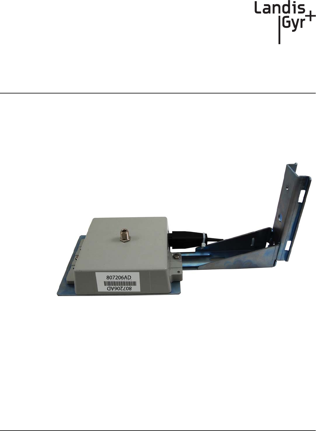
The Landis+Gyr Gridstream RF Series IV Mesh Extender is a 600mW radio transceiver operating in
the 902-928 MHz unlicensed ISM band in conjunction with other Landis+Gyr Gridstream RF radios.
It is designed to extend the range of the network in rural environments, where the distance between
neighboring endpoints is too great for them to communicate reliably.
Figure 1 - 1. Landis+Gyr Gridstream RF Series IV Mesh Extender
FCC and Industry Canada Compliance
FCC Class B
This device complies with Part 15 of the FCC rules. Operation is subject to the following two condi-
tions:
1. This device may not cause harmful interference, and
2. This device must accept any interference received, including interference that may cause
undesired operation.
DRAFT 5.14.2012

Chapter 1 - Introduction and Overview Landis+Gyr
6 98-1178 Rev AA Installation and User Guide
This equipment has been tested and found to comply with the limits for a Class B digital device, pur-
suant to Part 15 of the FCC Rules. These limits are designed to provide reasonable protection against
harmful interference in a residential installation. This equipment generates, uses, and can radiate radio
frequency energy and, if not installed and used in accordance with the Instructions, may cause harmful
interference to radio communications. However, there is no guarantee that interference will not occur
in a particular installation. If this equipment does cause harmful interference to radio or television re-
ception, which can be determined by turning the equipment off and on, the user is encouraged to try
to correct the interference by one or more of the following measures:
•Reorient or relocate the receiving antenna.
•Increase the separation between the equipment and receiver.
•Consult Landis+Gyr or an experienced radio technician for help
UWARNING: Changes or modifications to this device not expressly approved by Landis+Gyr
could void the user’s authority to operate the equipment.
RF Exposure
This equipment complies with FCC radiation exposure limits set forth for an uncontrolled
environment. This equipment should be installed and operated with minimum distance 22cm
between the radiator and your body. This transmitter must not be co-located or operating in
conjunction with any other antenna or transmitter.
Industry Canada
This device complies with Industry Canada licence-exempt RSS standard(s). Operation is subject to
the following two conditions: (1) this device may not cause interference, and (2) this device must
accept any interference, including interference that may cause undesired operation of the device.
Under Industry Canada regulations, this radio transmitter may only operate using an antenna of a
type and maximum (or lesser) gain approved for the transmitter by Industry Canada. To reduce
potential radio interference to other users, the antenna type and its gain should be so chosen that the
equivalent isotropically radiated power (e.i.r.p.) is not more than that necessary for successful
communication.
This radio transmitter 5294A-NG6R2S4 has been approved by Industry Canada to operate with the
antenna types listed below with the maximum permissible gain and required antenna impedance for
each antenna type indicated. Antenna types not included in this list, having a gain greater than the
maximum gain indicated for that type, are strictly prohibited for use with this device.
Approved Antenna: Landis+Gyr 106119-000: Antenna, Whip, 5 dBi Gain,
Le présent appareil est conforme aux CNR d'Industrie Canada applicables aux appareils radio
exempts de licence. L'exploitation est autorisée aux deux conditions suivantes : (1) l'appareil ne doit
pas produire de brouillage, et (2) l'utilisateur de l'appareil doit accepter tout brouillage
radioélectrique subi, même si le brouillage est susceptible d'en compromettre le fonctionnement.
Conformément à la réglementation d'Industrie Canada, le présent émetteur radio peut fonctionner
avec une antenne d'un type et d'un gain maximal (ou inférieur) approuvé pour l'émetteur par Industrie
Canada. Dans le but de réduire les risques de brouillage radioélectrique à l'intention des autres utilis-
DRAFT 5.14.2012

Landis+Gyr Chapter 1 - Introduction and Overview
Installation and User Guide 98-1178 Rev AA 7
ateurs, il faut choisir le type d'antenne et son gain de sorte que la puissance isotrope rayonnée équiv-
alente (p.i.r.e.) ne dépasse pas l'intensité nécessaire à l'établissement d'une communication
satisfaisante.
Le présent émetteur radio (5294A-NG6R2S4) a été approuvé par Industrie Canada pour fonctionner
avec les types d'antenne énumérés ci-dessous et ayant un gain admissible maximal et l'impédance
requise pour chaque type d'antenne. Les types d'antenne non inclus dans cette liste, ou dont le gain
est supérieur au gain maximal indiqué, sont strictement interdits pour l'exploitation de l'émetteur.
Référence: 106119-000: Antenne fouet, 5dBi, 915MHz, N Con., 50 ohms
Standards Compliance
The Gridstream RF Series IV Mesh Extender contains Smart Utility Network (SUN) 802.15.4g
ready hardware.
DRAFT 5.14.2012
DRAFT 5.14.2012

2
Installation and User Guide 98-1178 Rev AA 9
Installation
For All Installations
Proper planning and thorough preparation are critical to successful installation of the Landis+Gyr
Gridstream RF Series IV Mesh Extender (Extender).
Safety Overview
Prior to starting the installation process, you must develop and launch an installer safety training
plan for initial, refresher and ongoing safety training. Ensure that installers receive appropriate initial
and refresher training to meet their specific safety-related responsibilities. You must provide safety
training when:
•An existing installer assumes new duties for which he or she has not previously received
training.
•New processes and methodologies representing new risks are introduced into the installation
environment.
•Previously unidentified risks are reported
The installation supervisory team assumes responsibility for ensuring that installers are properly
trained, authorized, and continually qualified to perform their work. The team must also take
responsibility for the safety of their installers and to assure safe work methodologies. Installers must
understand that their supervisor’s responsibility does not relieve them from their individual
responsibility to perform the work safely and to follow all safety rules and procedures applicable to
their work
Safety Precautions
Each individual utility will have its own interpretation of local codes and regulations governing the
installation and placement of equipment on a power distribution pole. The utility or municipality
determines the final guidelines of where to install the . Know and follow the utility or municipality
guidelines before installing the Extender.
UWARNING: Follow all local safety precautions for working around high voltage lines.
ACAUTION: Follow all FCC regulations for placement of the Extender on the pole.
DRAFT 5.14.2012

Chapter 2 - Installation Landis+Gyr
10 98-1178 Rev AA Installation and User Guide
Extender Installation Overview
The final guidelines provided by the utility or municipality determine where the Extender can be
installed. It is the installer’s responsibility to know and follow the utility or municipality guidelines
before installing the Extender.
The utility provides installation information for every Extender to be installed, such as:
•Street address or Latitude/Longitude of site location.
•Type of mounting (wood pole, streetlight pole, building, etc.)
•Access method (bucket truck or climbed manually).
Power Requirements
Verify that the power source between 120 VAC and 240 VAC. Power source must have a constant
supply of voltage.
NOTE: Poles selected for Extender installation must have a constant supply of voltage. Many
streetlights are fed by a switched source that is controlled by a master switch, elsewhere. A pole
that is powered only half a day, everyday will produce a failure condition.
Antenna
The Extender requires an antenna to communicate with the endpoints and to relay information from
the endpoint to the host application. The antenna is mounted directly to the top of the Extender
enclosure by means of an N-type connector. Only the authorized antenna (provided with the
Extender) may be used. The Extender may be orientated with the antenna either up or down to obtain
the best communication path for your location.
NOTE: If the Extender is mounted upside down (antenna up), always inspect and verify the
presence of an O-ring on the antenna base. The O-ring is included with the antenna. Verify that the
O-ring has no physical deformities that could compromise the water tight seal at the base of the
antenna.
Parts and Materials
When receiving system components, carefully inspect the packaging and contents for any damage,
and file any necessary damage claims with the shipper. The table below lists all Extender-related
installation parts. (However, not all parts shown will necessarily be needed in every installation.)
Table 2-1. Extender Installation Components
Description Part Number Qty
Series IV Mesh Extender, Packaging, 10’ AC Power Cable 45-1215 1
DRAFT 5.14.2012

Landis+Gyr Chapter 2 - Installation
Installation and User Guide 98-1178 Rev AA 11
NOTE: 45-1216 does not come with a power cable. Your choice of optional cable assemblies
available are 19-1214, 19-1216, or 19-1221.
45-1215 Components
Antenna-Whip 106119-000 1
Cable Assembly, AC Power, UME, 10', #10AWG
Solid 19-1196 1
Series IV Mesh Extender 26-1903 1
Series IV Mesh Extender, Packaging, Without Power Cable 45-1216 1
45-1216 Components
Antenna-Whip 106119-000 1
Series IV Mesh Extender 26-1903 1
Landis+Gyr RF Mesh Extender Mounting Kit, Street Light Arm 45-1098 1
45-1098 Components
Nut, Serrated Hex Flange Lock Nut, 1/4-20UNC,
SS 101983-025 2
Washer, 1/4” Flat 1/16 Thick, SS 22-0421 2
Washer, Spring Lock, ID .26", SS 22-1147 2
Washer, ID .266", OD .563" X .056", SS 22-1151 2
Bolt, Hex Head, 1/4-20 x 3/4”, SS 22-1160 2
Bracket, Mounting, Wood Pole
(Optional: Sold Separately) 22-1299 0
Bracket, Streetlight Pole Mount 28-1312 1
V-Bolt, ¼-20”, Pole Mount, 1.5” to 4” Pipe
Diameter 28-1313 1
Cable Tie, 5.6 inch Length, UV, Nylon, Black 30-0055 2
Landis+Gyr RF Mesh Extender Hardware Kit 45-1093 1
45-1093 Components
Conn, Ground Barrel Lug,1 /4inch 16-1306 1
Screw, 1/4-20 X 3/4", Phillips, Pan Head, SS 22-1146 3
Washer, Spring Lock, ID.26", SS 22-1147 2
Screw, 10-32 X 3/8", Phillips, Pan Head, Self
Tapping, SS 22-1148 1
Washer, ID .266", OD .563" X .056", SS 22-1151 2
Mounting Bracket 28-1287 1
Cable Tie, 5.6 inch Length, UV, Nylon, Black 30-0055 2
Landis+Gyr RF Mesh Extender Antenna, Whip, 5 dBi 915 MHz, N Type 106119-000 1
Landis+Gyr RF Mesh Extender AC Power Cable Assembly, 30’ 19-1221 1
Landis+Gyr RF Mesh Extender Streetlight Cable Assembly, 6’ 19-1216 1
Landis+Gyr RF Mesh Extender Streetlight Cable Assembly, 18’ 19-1214 1
Table 2-1. Extender Installation Components
Description Part Number Qty
DRAFT 5.14.2012
Chapter 2 - Installation Landis+Gyr
12 98-1178 Rev AA Installation and User Guide
Attach Extender to Standard Mounting Bracket
1. Install the Extender to the mounting bracket in the orientation as shown in Figure 2 - 1:
•Insert screw (A), with a spring washer (B) and a flat washer (C) in the center hole of each
side of the Extender and align to the pem nuts in the mounting bracket (D).
Figure 2 - 1. Attach Extender to the Mounting Bracket
2. Insert the plug of the AC cable (E) into the AC socket (F).
Figure 2 - 2. Attach AC Cable
A
B
C
D
E
F
DRAFT 5.14.2012
Landis+Gyr Chapter 2 - Installation
Installation and User Guide 98-1178 Rev AA 13
NOTE: Be sure to push the plug all the way in and feel a click to lock the AC cable.
3. Insert and tighten two UV stable tie wraps (G) to attach the AC cable, while making sure the
cable is straight and not twisted up or down relative to its mating connector.
Figure 2 - 3. Tighten Cable Ties
G
DRAFT 5.14.2012
Chapter 2 - Installation Landis+Gyr
14 98-1178 Rev AA Installation and User Guide
Grounding (Optional)
If a ground wire is required for your installation, a 6 AWG solid copper wire is recommended.
1. Install a 6 AWG solid copper wire ground connector (A) by tightening the screw (B).
2. Insert the grounding wire (C) through the ground connector and into the small hole in the
enclosure (D).
3. Insert and tighten the screw (E) to fix the wire as shown.
4. Tighten the set screw (F) on the ground connector.
Figure 2 - 4. Install Ground Connector
Wood Pole Mount Installation
Required Tools
•Installation sheet
•Extender & applicable installation kit
•Extender power cable
•Extender antenna
•Optinal 6 AWG solid copper ground wire
•Personal protection equipment
•Power disconnect box
•Power drill with level, 3/4 inch augur bit
•Adjustable-end wrenches
•Standard socket wrench set
•Wire strippers
•Screwdrivers
AB
C
D
E
F
DRAFT 5.14.2012
Landis+Gyr Chapter 2 - Installation
Installation and User Guide 98-1178 Rev AA 15
•Volt meter
•5/8” DA bolt with two nuts and washers
•Miscellaneous hardware as required for installation and grounding
Wood Pole Installation Procedure
The following procedure details Extender installation on a standard wood utility pole. Ensure that
required tools and materials are on hand and available.
1. Mount the Extender and grounding components, if required, to the mounting bracket with the
hardware provided.
2. Drill one, 3/4-inch diameter hole in the utility pole. The hole must be centered side-to-side on
the pole. Hole must be straight and level through the middle of pole.
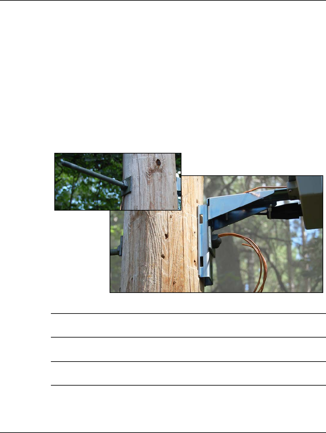
3. Hold the Extender and mounting bracket in place and insert 5/8-inch DA bolt through the center
mounting bracket hole. Place washers and nuts on both side of the pole.
Figure 2 - 5. Attach Mounting Bracket to Wood Pole
NOTE: The Extender may be mounted with either an Up or Down antenna orientation to obtain the
best communication path for your location.
4. Tighten the bolt on side of pole opposite the Extender firmly.
NOTE: 1/4” lag bolts may be used on the top and bottom holes of the mounting bracket for extra
stability.
5. Mount the optional power disconnect box on the pole according to local codes and best
practices.
DRAFT 5.14.2012
Chapter 2 - Installation Landis+Gyr
16 98-1178 Rev AA Installation and User Guide
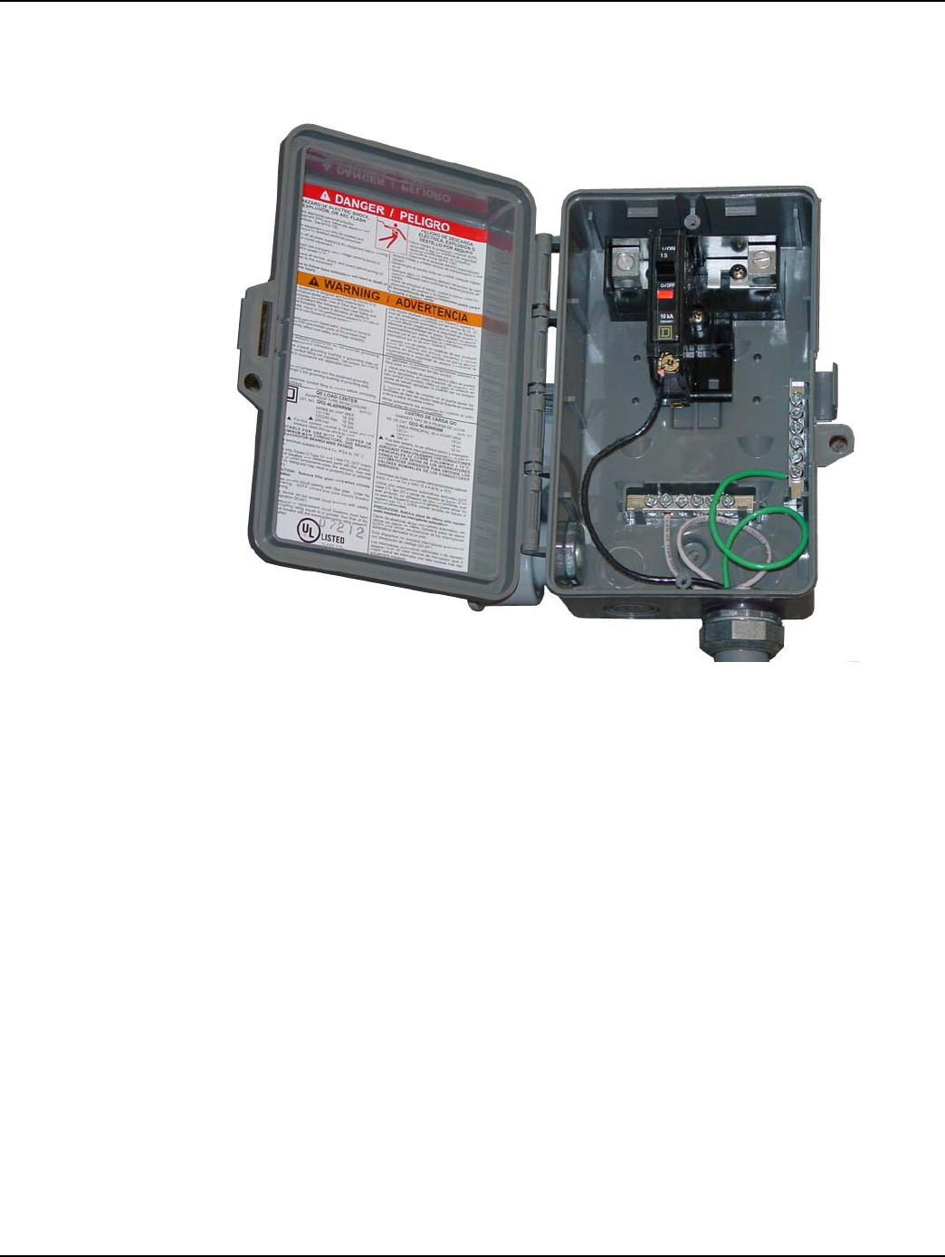
6. Attach the wires from the Extender to the screws on the terminal blocks inside the power
disconnect box. Provide enough tension relief and a drip loop on the power cable below the
power disconnnect box.
Figure 2 - 6. Sample Power Disconnect Option
•For any cables in an assembly, allow some slack to rest below metal parts. The slack is
called a “drip loop”. With a drip loop, water from rain and condensation drips from the cable
without damaging associated mechanical equipment.
7. With the power disconnect switch in the OFF (open) position, make the connection between the
Extender, power disconnect switch, and power source according to local codes and best
practices.
•Installations where the power cable is wired directly to the power source must be sealed with
waterproofing compound to prevent water ingress into the power cable.
DRAFT 5.14.2012
Landis+Gyr Chapter 2 - Installation
Installation and User Guide 98-1178 Rev AA 17
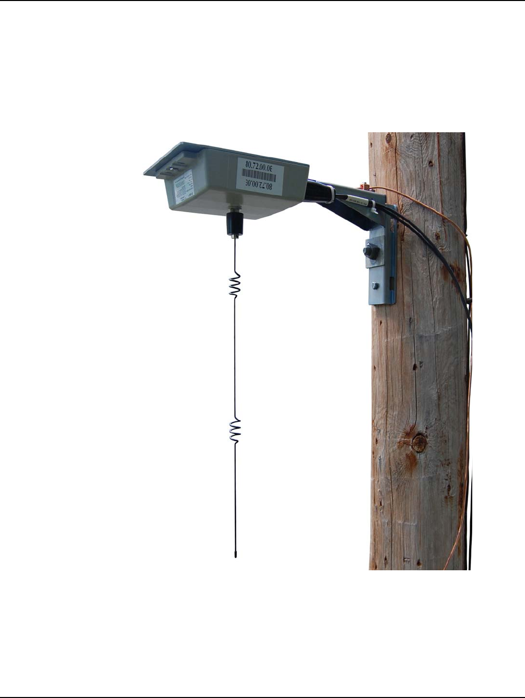
8. Securely hand tighten the included antenna on the antenna mounting connector of the Extender.
•If the Extender is mounted upside down (antenna up), always inspect and verify the presence
of an O-ring on the antenna base. The O-ring is included with the antenna. Verify that the O-
ring has no physical deformities that could compromise the water tight seal at the base of the
antenna.
•The antenna should never be more than 10° off in any direction from being perpendicular to
the ground.
Figure 2 - 7. Attach Antenna
9. Connect the grounding wire, if required, to the pole ground or neutral ground as local code
allows. If no ground wire is present, install a 8’ by 5/8” copper clad steel ground rod and connect
with the proper clamp. Attach the ground wire to the pole with the proper staples and standard
spacing.
A. Be sure to avoid right angle or sharp bends in routing the ground wire.
B. Bond this ground wire to the power neutral if local rules require.
DRAFT 5.14.2012

Chapter 2 - Installation Landis+Gyr
18 98-1178 Rev AA Installation and User Guide
10. Secure power cable to pole as needed.
NOTE: While securing the power cable to the pole, care must be taken to NOT DAMAGE the outer
jacket of the power cable. A nick in the outer jacket will allow water to migrate inside the power
disconnect switch and flood it.
Provide enough tension relief and a drip loop for the power cable.
11. Energize the Extender by moving the power disconnect to the ON (closed) position in the
installed power disconnect box.
Metal Pole Mount Installation
Required Tools
•Installation sheet
•Extender & applicable installation kit
•Extender power cable
•Extender antenna
•UV stable tie wraps
•6 AWG solid copper ground wire (optional)
•Personal protection equipment
•Power disconnect box
•Adjustable-end wrenches
•Standard socket wrench set
•Wire strippers
•Steel bands
•Steel banding tool
•Screwdrivers
•6 AWG solid copper wire ground connector (optional)
•Miscellaneous hardware as required for installation and grounding
Metal Pole Installation Procedure
The following procedure details Extender installation on a standard metal utility pole. Ensure that
required tools and materials are on hand and available.
1. Mount the Extender and grounding components, if required, to the mounting bracket with the
hardware provided.
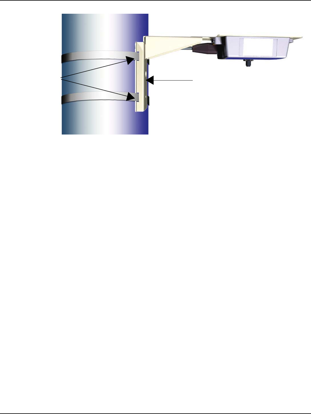
2. Install two stainless steel pole mount band clamps (A) through the slots on the back of the
mounting bracket (B) and secure around pole. The Extender should be straight and level on the
pole.
DRAFT 5.14.2012
Landis+Gyr Chapter 2 - Installation
Installation and User Guide 98-1178 Rev AA 19
Figure 2 - 8. Steel Pole Mount
3. Hold the Extender and mounting brackets in place and tighten band clamps.
•The Extender may be mounted with either an Up or Down antenna orientation to obtain the
best communication path for your location.
4. Mount the optional power disconnect box on the pole with stainless steel band and brackets or
non-corrosive bolts to tapped holes, according to local codes and best practices.
5. Attach the wires from the Extender to the screws on the terminal blocks inside the power
disconnect box.
•For any cables in an assembly, allow some slack to rest below metal parts. The slack is
called a “drip loop”. With a drip loop, water from rain and condensation drips from the cable
without damaging associated mechanical equipment.
6. With the power disconnect switch in the OFF (open) position, make the connection between the
Extender, power disconnect switch, and power source according to local codes and best
practices.
•Installations where the power cable is wired directly to the power source must be sealed with
waterproofing compound to prevent water ingress into the power cable.
7. Using UV stable tie wraps, secure the power cable to the pole.
•Landis+Gyr recommends tie wraps that are 1/2” to 3/4” wide.
•While securing the power cable to the pole, care must be taken to NOT DAMAGE the outer
jacket of the power cable. A nick in the outer jacket will allow water to migrate inside the
power disconnect switch and flood it.
•Provide enough tension relief and a drip loop for the power cable.
8. Securely hand tighten the included antenna on the antenna mounting connector on the Extender.
•The antenna should never be more than 10° off in any direction from being perpendicular to
the ground.
•If the Extender is mounted upside down (antenna up), always inspect and verify the presence
of an O-ring on the antenna base. The O-ring is included with the antenna. Verify that the O-
ring has no physical deformities that could compromise the water tight seal at the base of the
antenna.
AB
DRAFT 5.14.2012

Chapter 2 - Installation Landis+Gyr
20 98-1178 Rev AA Installation and User Guide
9. Connect the grounding wire, if required, to the pole ground or neutral ground as local code
allows. If no ground wire is present, install a 8’ by 5/8” copper clad steel ground rod and connect
with the proper clamp. Attach the ground wire to the pole with the proper staples and standard
spacing.
A. Be sure to avoid right angle or sharp bends in routing the ground wire.
B. Bond this ground wire to the power neutral if local rules require.
10. Energize the Extender by moving the power disconnect to the ON (closed) position in the
installed power disconnect box.
DRAFT 5.14.2012
Landis+Gyr Chapter 2 - Installation
Installation and User Guide 98-1178 Rev AA 21
Streetlight Arm Mount Installation
VERIFY this street light has power 24/7 and is NOT remotely switched.
Mount Extender to Streetlight Bracket
The following procedure details Extender installation on a standard steetlight arm. Ensure that
required tools and materials are on hand and available.
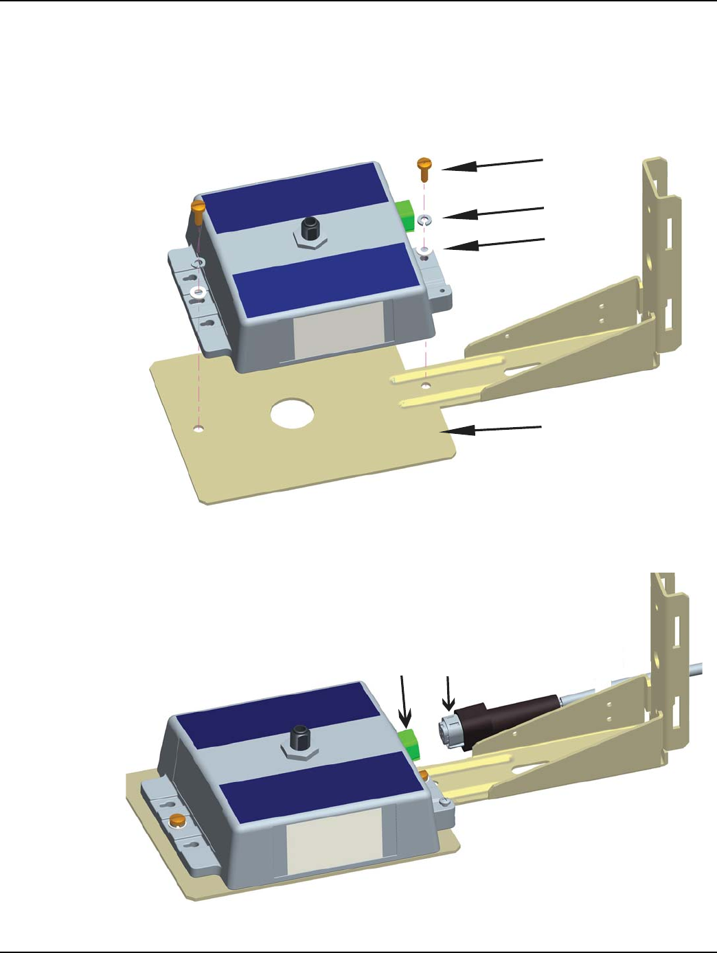
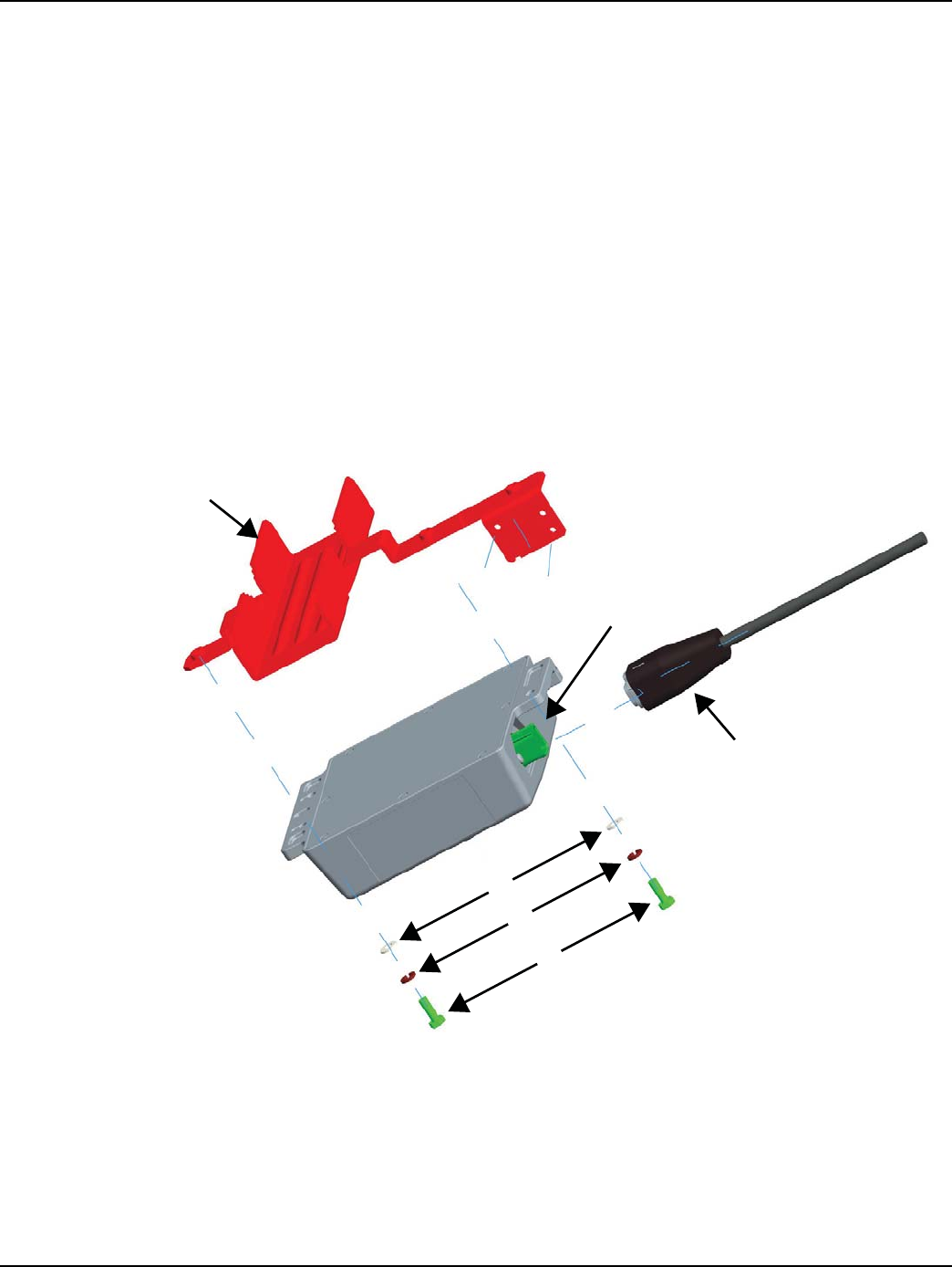
1. Attach the Extender to the streetlight mounting bracket.
A. Insert bolt (A), with a spring washer (B) and a flat washer (C) in the center hole of each side
of the Extender and align to the holes in the mounting bracket (D).
B. Tighten the screws with a torque of 45 in. lb.
C. Insert the connector of the AC power cable (E) into the AC power socket (F). Be sure to
push the connector all the way down until you feel a click which indicates the power cable is
fully engaged.
Figure 2 - 9. Mount to Streetlight Bracket
C
B
A
D
E
F
DRAFT 5.14.2012
Chapter 2 - Installation Landis+Gyr
22 98-1178 Rev AA Installation and User Guide
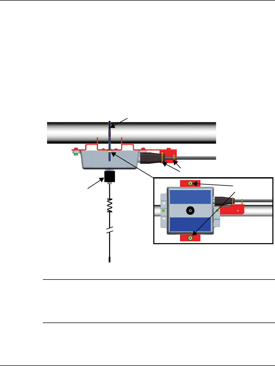
Mount on Streetlight Arm
The Extender may be mounted with either an Up or Down antenna orientation to obtain the best
communication path for your location.
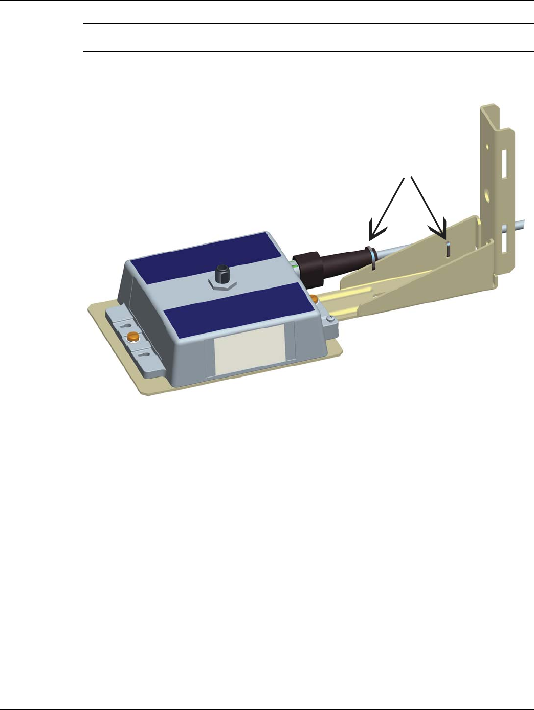
1. Attach the Extender to the streetlight arm.
A. Place the V-Bolt (A) over the streetlight arm and through the holes in the streetlight bracket.
B. Hold Extender in position and place washers (B) and nuts (C) on the threaded ends of the
bolts and torque to 45 +/- 5 lbs.
C. Tighten the two tie wraps (D) to fix the power cable to the bracket, while making sure the
cable is straight and not twisted up or down relative to its mating connector.
D. Securely hand tighten the included antenna (E) on the antenna mounting connector of the
Extender.
Figure 2 - 10. Mount to Streetlight Arm
NOTE: The antenna should never be more than 10° off in any direction from being perpendicular to
the ground.
If the Extender is mounted upside down (antenna up), always inspect and verify the presence of an
O-ring on the antenna base. The O-ring is included with the antenna. Verify that the O-ring has no
physical deformities that could compromise the water tight seal at the base of the antenna.
2. To connect the adapter, remove the photocell on the existing light head.
3. Install the adapter.
4. Lock it into place by turning clockwise.
A
B/C
D
E
DRAFT 5.14.2012
Landis+Gyr Chapter 2 - Installation
Installation and User Guide 98-1178 Rev AA 23
5. Re-install the photocell in the same manner.
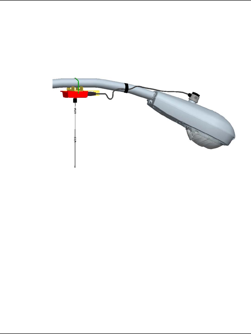
6. Using UV stable tie wraps, secure the power cable to the light head.
•Landis+Gyr recommends that tie wraps be the steroid version - about 1/2” to 3/4” wide and
very thick.
•While securing the power cable to the streetlight arm, care must be taken to NOT DAMAGE
the outer jacket of the power cable. A nick in the outer jacket will allow water to migrate
inside the Extender or the adapter.
•Provide enough tension relief and a drip loop for the power cable.
Figure 2 - 11. Extender Mounted on Streetlight Arm
DRAFT 5.14.2012
Chapter 2 - Installation Landis+Gyr
24 98-1178 Rev AA Installation and User Guide
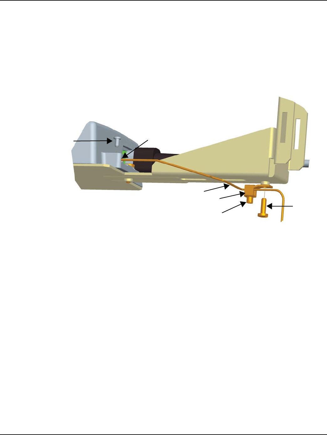
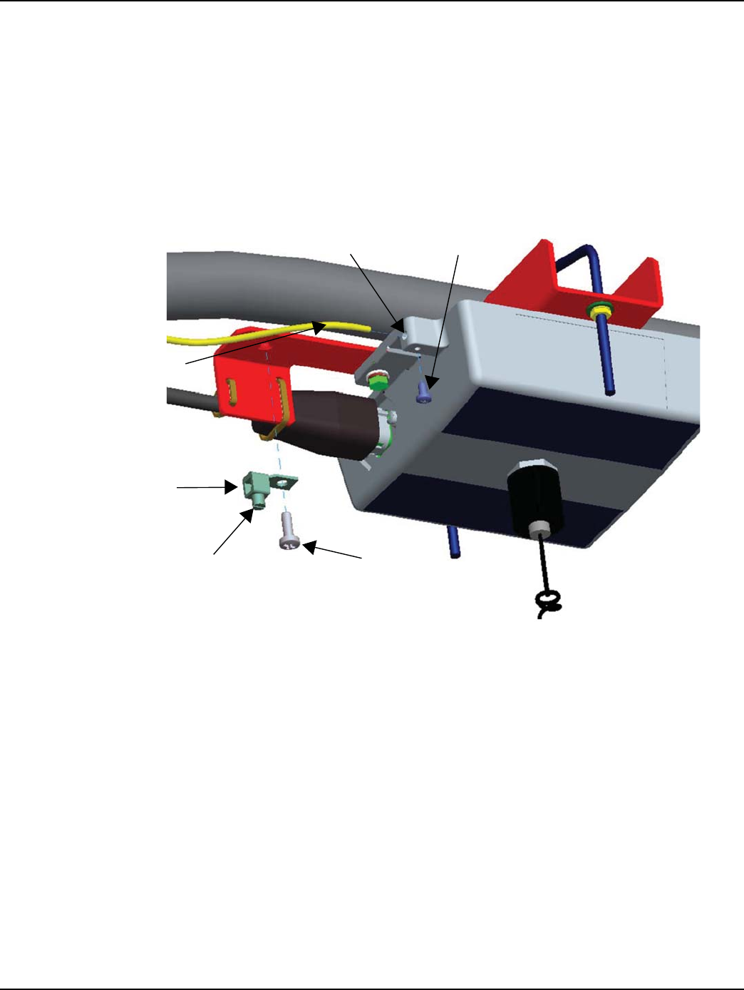
Grounding (Optional)
If a ground wire is required for your installation, a 6 AWG solid copper wire is recommended.
1. Install a 6 AWG solid copper wire ground connector (A) by tightening the screw (B).
2. Insert the grounding wire (C) through the ground connector and into the small hole in the
enclosure (D).
3. Insert and tighten the screw (E) to fix the wire as shown.
4. Tighten the set screw (F) on the ground connector.
Figure 2 - 12. Attach Ground Wire
DE
A
B
F
C
DRAFT 5.14.2012
Installation and User Guide 98-1178 Rev AA 25
3
RadioShop and Endpoint
Testing Manager (ETM)
Configuration Using RadioShop
Wireless Configuration
RadioShop 5.3 (or later), may be used for network configuration of the Extender.
After the Extender has been installed, you may use a computer to connect to a local head-end radio
(IWR), which will then be used to communicate with the Extender over the air.
For further assistance on how to connect to your local head-end radio, please refer to the latest
RadioShop user's manual.
Connect to Your Local Radio using RadioShop
Connect the LAN Packet Protocol port of your IWR to your computer's serial port using a serial
cable. Once the radio is powered up, you can launch RadioShop on your computer. RadioShop will
now connect to your local head-end radio (IWR).
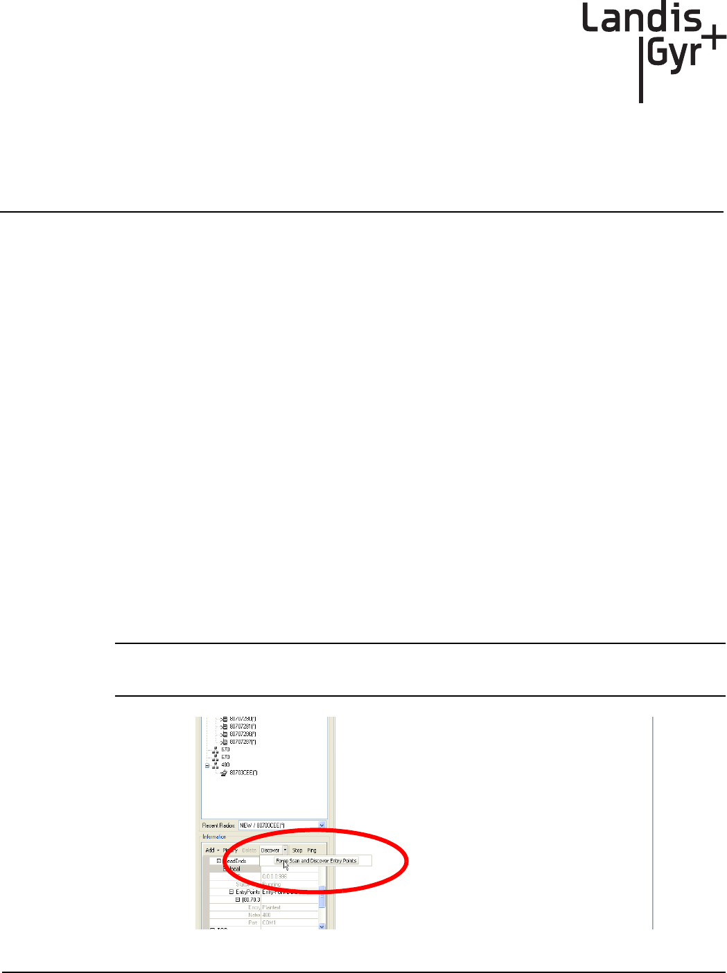
1. Open RadioShop.
2. From RadioShop home select the Head-End Mgmt tab.
3. Click Discover > Force Scan > Discover Entry Ports, or click Start.
NOTE: When the Select COM Ports for Discovery window opens, select the COM port on your
computer that is connected to the radio, and then click OK.
Figure 3 - 1. Connecting to Head-End Radio
DRAFT 5.14.2012
Chapter 3 - RadioShop and Endpoint Testing Manager (ETM) Landis+Gyr
26 98-1178 Rev AA Installation and User Guide
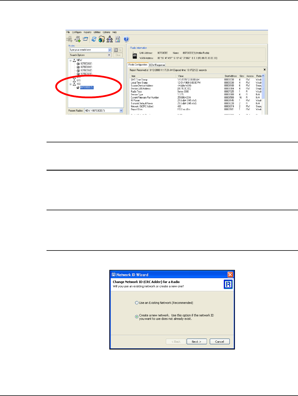
4. Once connected, the local radio's LAN address will appear on the list at the top left-hand side of
the screen, and a radio configuration report will be displayed in the main window.
Figure 3 - 2. Local Radio LAN Address
5. If your Extender is new, you must make sure your Local Radio is on Network ID 670.
NOTE: In the example above, the Network Id of the Local Radio is 450. It must be changed to 670
to be able to communicate with a new Extender. If the Extender already has been assigned a
network ID, the radio must be changed to match.
Configure Local Radio to Match the Extender Network ID
To change the Network ID of the Local Radio, perform the following steps.
NOTE: All Landis+Gyr Gridstream radios, including the Extender, ship with a default network ID, or
CRC, of 670. In order to communicate with the new Extender, your local radio will have to be
reconfigured to match the network ID (670) of the Extender. After reconfiguring the Extender to
match the customer’s unique network ID, the local radio will need to be reset to its original network
ID.
1. Select Configure > Change Network Id (CRC)..., the Network ID Wizard is displayed.
Figure 3 - 3. Specify New Network
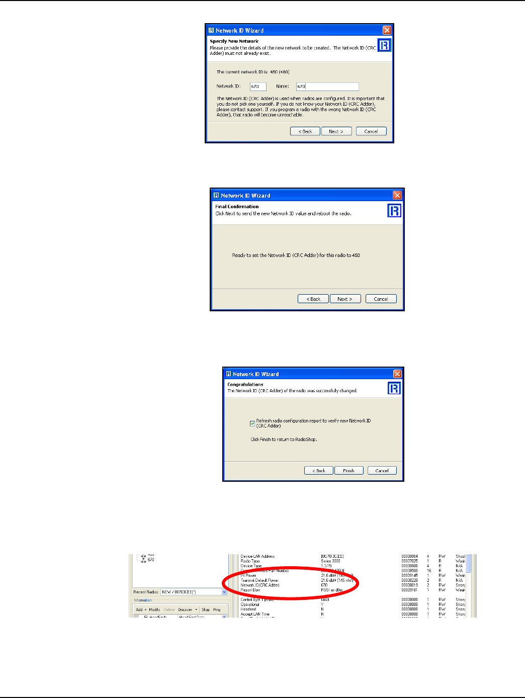
2. Click Next.
3. Specify 670 or Extender’s ID for both the Network ID and Name of the new network, and click
Next to continue.
DRAFT 5.14.2012
Landis+Gyr Chapter 3 - RadioShop and Endpoint Testing Manager (ETM)
Installation and User Guide 98-1178 Rev AA 27
Figure 3 - 4. Network ID 670
4. The Final Confirmation window will open. Click Next.
Figure 3 - 5. Final Confirmation Window
5. A confirmation message verifies that the new Network ID has been assigned to the radio. Click
Finish to return to RadioShop.
Figure 3 - 6. Click Finish to Finalize Configuration
6. RadioShop will reboot your Local Radio and run another Radio Configuration Report.
7. Make sure the Network ID of your Local Radio has changed. If the Radio Configuration Report
times out, run another one.
Figure 3 - 7. Network ID is Now 670
Adding New Radios to RadioShop
You can now add the Extender to the RadioShop database.
DRAFT 5.14.2012
Chapter 3 - RadioShop and Endpoint Testing Manager (ETM) Landis+Gyr
28 98-1178 Rev AA Installation and User Guide
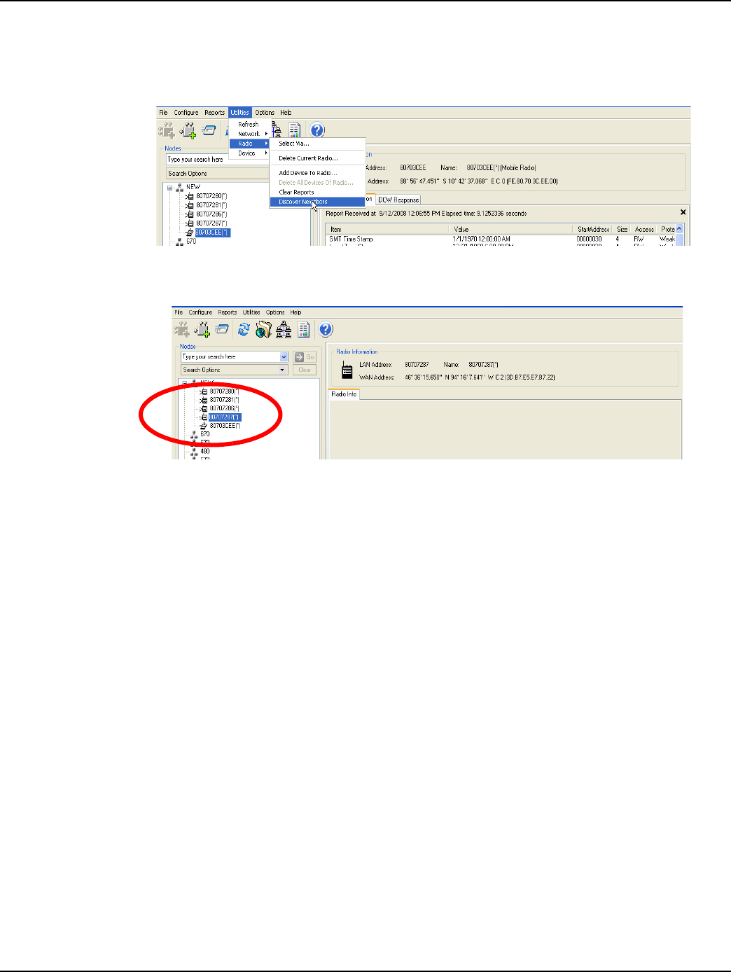
1. Make sure your local radio is highlighted on the Nodes Pane.
2. Click Generate WAN Nodes Report.
3. From RadioShop home click Utilities > Radio > Discover Neighbors.
Figure 3 - 8. Discovering Neighbors
4. Once discovered, the Extender’s LAN Address will show up on the Nodes pane.
Figure 3 - 9. Extender Added to Nodes Pane
5. Highlight the new Extender, and click Reports > Configuration > Radio to verify that you can
communicate with the Extender.
Locate your Extender using RadioShop
The Extender must be connected to power for configuration.
1. Click Generate WAN Nodes Report on the toolbar.
2. Right-Click your Local Radio and click Discover Neighbors.
3. Click your Extender’s LAN ID.
4. Generate a Radio Configuration Report to make sure that you can communicate with your
Extender.
Using ETM
If someone could tell me what ETM is used for regarding this product, I can probably find the
appropriate content.
DRAFT 5.14.2012
4
Installation and User Guide 98-1178 Rev AA 29
Extender Configuration in
Command Center
Overview
Similar to endpoints, Extenders will auto-register to Command Center. After the Extender has been
installed, it will attempt to auto register. For the Extender auto registration to complete successfully,
the following prerequisites must be observed.
•Correct Network ID must be coded into the Extender
•The Extender must be in Operational Mode
•The Extender must be loaded with Firmware version 4.0a .11 or later
•No WAN Address loaded into the Extender
•No GEO coordinates (LAT/LONG), loaded into the Extender
To complete the auto-registration process, a Meter Manufacturer File (MMF) must be imported into
Command Center.
Importing Extenders into Command Center
Meter Manufacturer File
The Meter Manufacturer File provides Command Center with information on the Extender ID and
the module serial number. This file is not currently provided at the time the Extenders are purchased,
and must be created using the MMF.csv template.
Create a Meter Manufacturer Data File
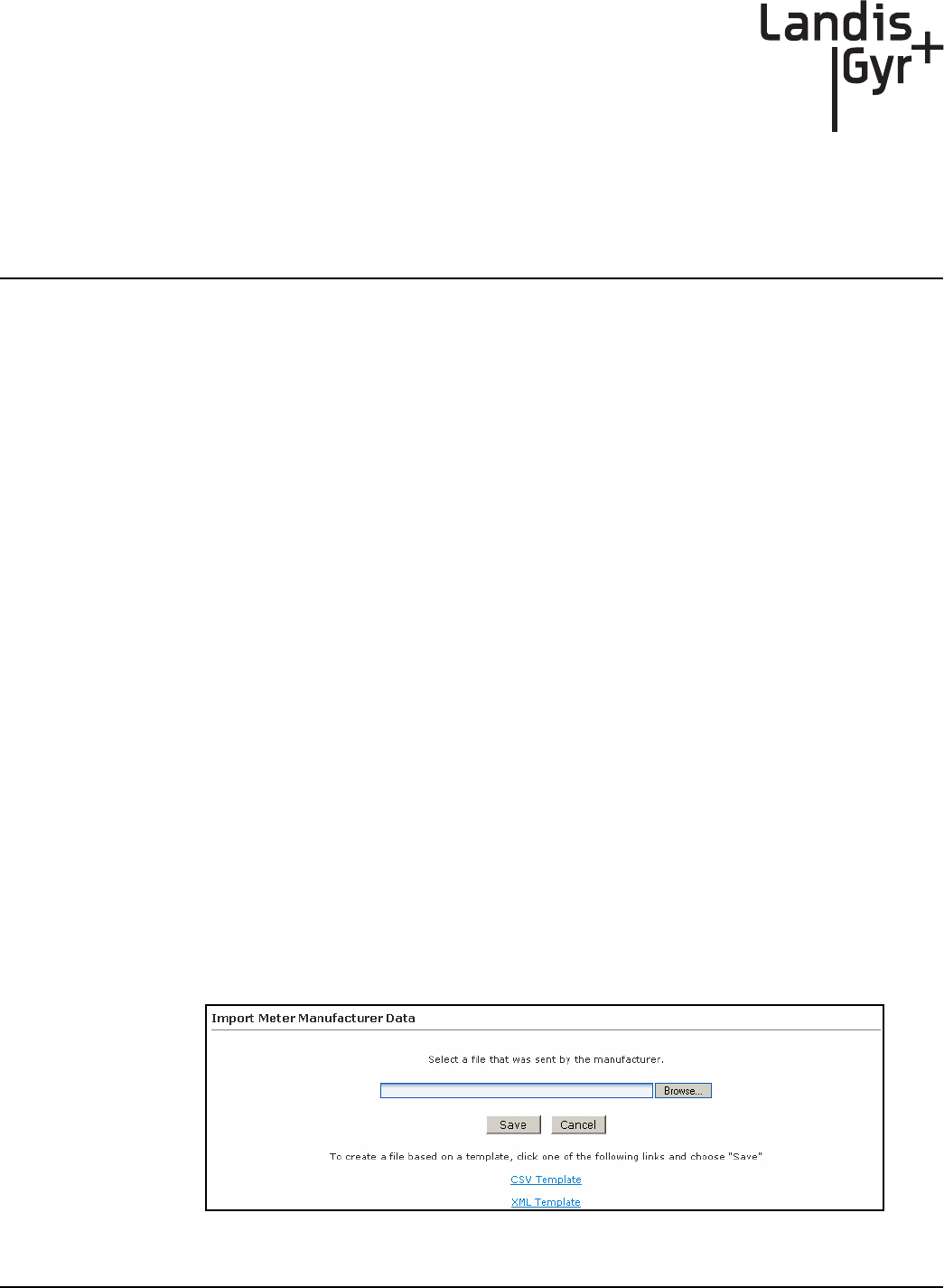
1. Click Operations > Import > Meter Manufacturer Data to display the Import Meter
Manufacturer Data screen shown in Figure 4 - 1.
Figure 4 - 1. Import Meter Manufacturer Data
DRAFT 5.14.2012
Chapter 4 - Extender Configuration in Command Center Landis+Gyr
30 98-1178 Rev AA Installation and User Guide
2. Click the CSV Template link.
3. Select Save and designate the file location.
4. Open up the saved .CSV file with Microsoft Excel.
5. Fill in the columns with the appropriate data. Each row in the document represents one Extender
(or Endpoint) and should only contain data related to that specific unit. Required fields are
Customer Number and AMR Serial Number.
6. Click the Save button and close your file.
Import the Meter Manufacturer File
1. Click Operations > Import > Meter Manufacturer Data to display the Import Meter
Manufacturer Data screen.
2. Click the Browse button to navigate to, and select, the file that you just created.
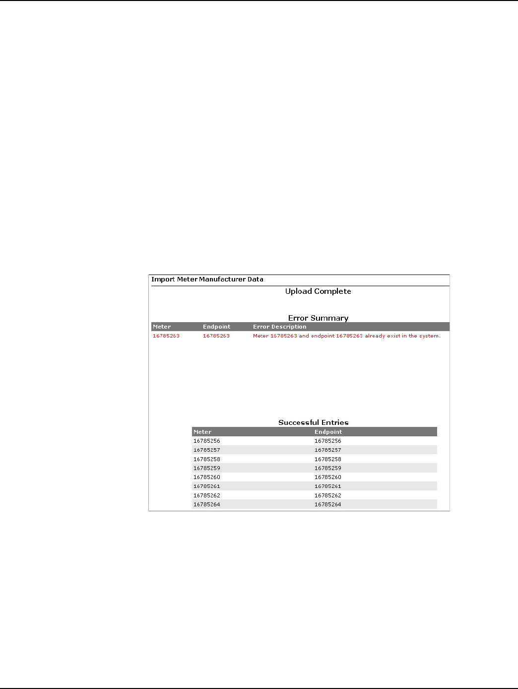
3. Click the Save button to import the file into the database.
The Meter Manufacturer Data Import (Upload Complete) window will appear displaying the
Error Summary (if applicable) and Successful Entries. Figure 4 - 2
Figure 4 - 2. Upload Complete Window
4. Successful entries will be added to inventory and will be displayed on the dashboard as
Inventory status.
Generating the Import Installation File (IIF) - Optional
When a Extender has been physically installed in the field, certain data may be reported back to the
Command Center staff in order to generate the IIF. The IIF is not required when deploying a layered
network, but provides useful data for monitoring deployments.
DRAFT 5.14.2012
Landis+Gyr Chapter 4 - Extender Configuration in Command Center
Installation and User Guide 98-1178 Rev AA 31
Create an Import Installation File
Following is the procedure to create An Import Installation File.
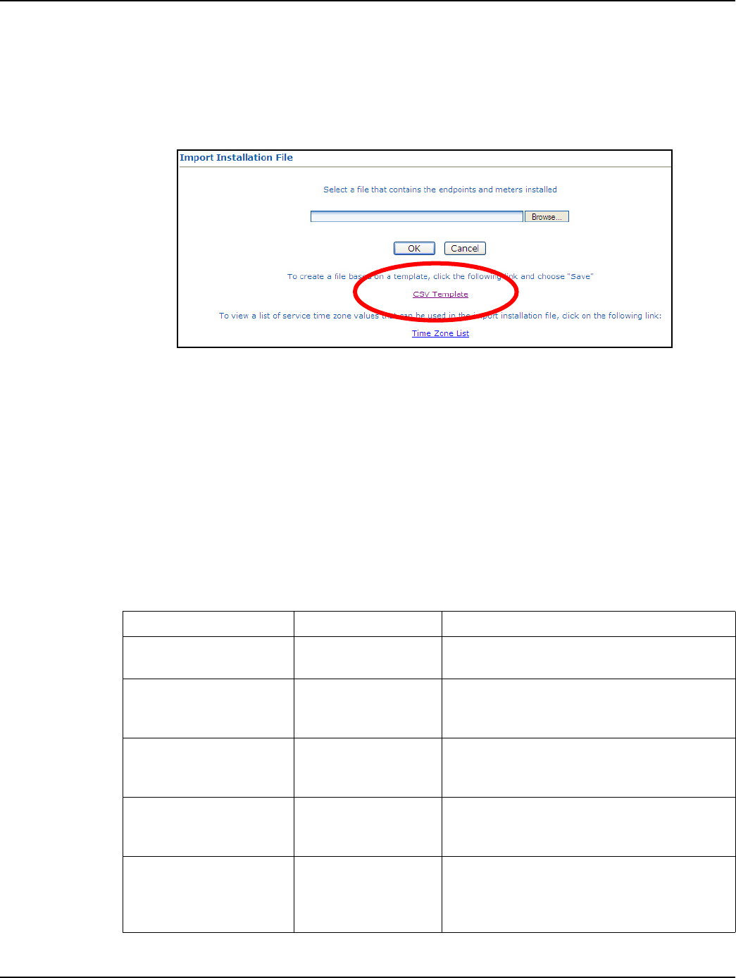
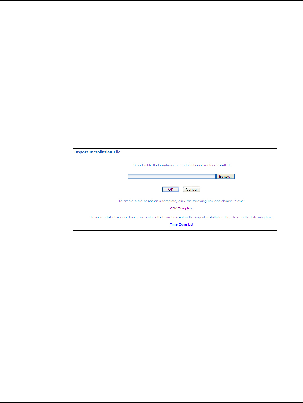
1. From Command Center home, select Operations > Import > Import Installation File.
The Import Installation File window will open.
Figure 4 - 3. Import Installation Window
2. Click the CSV Template link.
3. Select Save and designate the file location.
4. Open up the saved .CSV file with Microsoft Excel.
5. Fill in the columns with the appropriate data. Each row in the document represents one Extender
(or Endpoint) and should only contain data related to that specific unit.
CSV File Fields
Table 4-1.
Data Format Format/Description
User ID* AlphaNum (30) Login assigned by the utility for the installer.
Utility may elect to use “1” for System usage
Installation Date*
Date
MM/DD/YYYY
12/26/2009
Actual date the meter was installed. This date is
used in various Command Center reports to
track deployment statistics.
Installation Time* T i m e H H M M A M / P M
11:12 AM
Actual time the meter was installed. This date is
used in various Command Center Reports to
track deployment statistics.
Change Out meter number AlphaNum (20)
The meter being replaced with a new meter.
Meter change out information is displayed in the
notes section of the endpoint information screen.
Change Out meter kWh AlphaNum (20)
The kWh reading on the meter being replaced
Meter change out kWh information is displayed
in the notes section of the endpoint information
screen. Variable Character
DRAFT 5.14.2012
Chapter 4 - Extender Configuration in Command Center Landis+Gyr
32 98-1178 Rev AA Installation and User Guide
UWARNING: Required fields are UserID, Installed Date, InstalledTime, InstalledMeterNo, and
InstalledEndpointSN, Time Zone. If these fields are not populated, the file will not be
processed. For geo-coded routing Latitude, Longitude and Service Location are required.
Service Location is required if the Latitude and Longitude fields are populated. Command
Center will ignore the latitude and longitude values if Service Location is not provided.
Importing the IIF
After the IIF has been created and saved, it must be imported into Command Center.
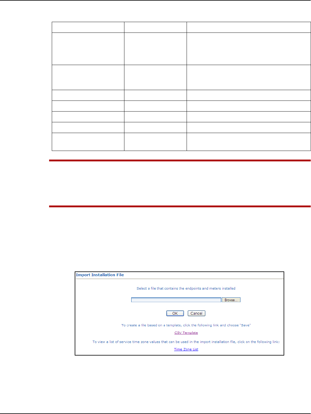
1. From Command Center home, select Operations > Import > Import Installation File.
The Import Installation File window will open.
Figure 4 - 4. Import Installation File Window
2. Enter the path to the location of the Import Installation File created earlier.
...or...
3. Click the Browse button to navigate to the location of the desired file.
Installed Meter Number* AlphaNum (20)
Meter number of the new meter being installed.
This meter must exist in Command Center prior
to importing the Import Installation File. Must
parse to Decimal format
Installed Endpoint Serial
Number* Decimal (9)
The serial number of the new meter being
installed. Note: Endpoint serial numbers must be
converted from Hex to Decimal.
Installed Meter kWh Decimal (9) Initial reading of the new meter.
Service Latitude Decimal (12,8) GPS latitude
Service Longitude Decimal (12,8) GPS longitude.
Service Location AlphaNum (100) Meter service location.
Service Time Zone* See formatting below. The service time zone may be entered to specify
the correct time zone for the service location.
Table 4-1.
Data Format Format/Description
DRAFT 5.14.2012
Landis+Gyr Chapter 4 - Extender Configuration in Command Center
Installation and User Guide 98-1178 Rev AA 33
4. Click Save to upload the file.
5. The Extender described in the IIF should now appear in Command Center. The Extender should
display the data entered for it and have the status 'Installed'.
Time Zone
In order to report readings time correctly, the Extender must be programmed with the appropriate
time zone. This is achieved by sending commands to the Extender that indicates the time zone in
which the endpoint is installed and whether Daylight Savings Time (DST) is observed in the given
time zone.
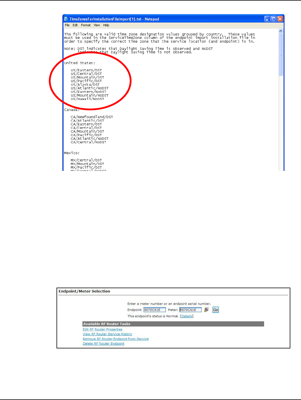
The meter installer should include the endpoint time zone in the Installation File. To make it easy for
installers to specify a time zone, the Time Zone List link will open a document that displays a list of
valid time zone designations by country.
1. From Command Center home, select Operations > Import > Import Installation File.
The Import Installation File window will open.
Figure 4 - 5. Import Installation File Window
2. Click on the Time Zone List Link. The TimeZonesForInstallation window will open.
DRAFT 5.14.2012
Chapter 4 - Extender Configuration in Command Center Landis+Gyr
34 98-1178 Rev AA Installation and User Guide
Figure 4 - 6. Time Zone List
3. Note the correct Time Zone Value for your IIF.
Extender Management
The RF Mesh Endpoint Information screen will also provide information about the Extenders and
Mesh Extenders in the utility’s RF Mesh system. This screen summarizes information about a
selected Extender and provides an interface for sending commands to the Extender.
Following is the procedure to view Gridstream RF Endpoint Information for a Extender from main
Command Center screen:
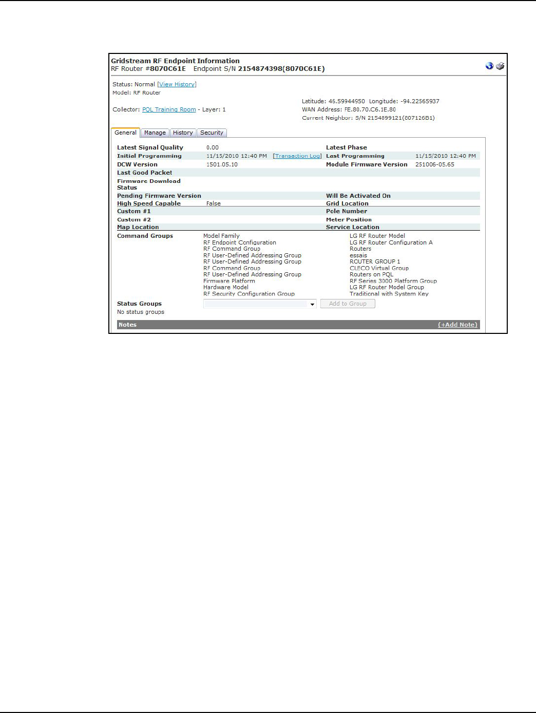
1. From Command Center home, select Operations > Endpoints. The Endpoint/Meter Selection
window will open.
Figure 4 - 7. Endpoint/Meter Selection
2. Enter the Extender Serial Number or Meter Number
3. Click Go. The Endpoint/Meter Selection screen will refresh and display tasks available for the
Extender.
DRAFT 5.14.2012
Landis+Gyr Chapter 4 - Extender Configuration in Command Center
Installation and User Guide 98-1178 Rev AA 35
4. Click the Details link. The Gridstream RF Endpoint Information Screen will open for the
Extender, shown in Figure 4 - 8
Figure 4 - 8. Gridstream RF Endpoint Information
The following information is displayed:
• Status. Displays the current status of the Extender. Select the View History link to see the
Status Changes window.
•Model. Displays the model type.
• Collector. Displays the name of the collector the Extender has most recently used for
communication. Select the Collector link to view the Collector screen.
• Latitude/Longitude. Displays the latitude and longitude of the endpoint.
• WAN Address. Displays the mobile WAN address assigned to the Extender.
The following tabs are available:
• General. The General Settings screen displays the endpoint’s current settings.
•Manage. The Manage screen allows the user to issue commands to the current Extender, as
well as, view commands previously issued.
•History. The History screen displays history of commands, events and errors logged by the
Extender.
• Security. The Security tab will be displayed to only the users with security permissions.
General Settings Tab
DRAFT 5.14.2012

Chapter 4 - Extender Configuration in Command Center Landis+Gyr
36 98-1178 Rev AA Installation and User Guide
Figure 4 - 9. General Settings Tab
The General Settings tab displays current Extender settings. Data displayed includes:
• Latest Signal Quality. N/A
• Latest Phase. N/A
• Initial Programming. Indicates the date the Extender was originally programmed and
deployed in the field.
• Last Programming. Displays the last date the Extender was programmed.
•Last Good Packet. Indicates the date of the last good packet received from this Extender.
• Firmware download status: This will display the progress of a new firmware download.
• Pending Firmware Version. Indicates the firmware version currently queued for download
to the Extender.
• Will be active on. Indicates the date the pending firmware version will be downloaded to
the Extender.
•Grid Location. Displays the Extender’s grid location (if applicable).
• Pole Number. Displays the Extender’s pole number (if applicable).
• Meter Position. Displays the Extender’s position (if applicable)
•Custom #1. User defined data field (if applicable)
•Custom #2. User defined data field (if applicable)
• Service Location. Displays the Extender’s service location number (if applicable).
• Command Groups. Displays the Extenders command group membership. A Extender may
be a member of 8 command groups.
•Notes. Lists notes entered by the user.
DRAFT 5.14.2012

Landis+Gyr Chapter 4 - Extender Configuration in Command Center
Installation and User Guide 98-1178 Rev AA 37
Manage Tab
The Manage screen, allows the user to issue commands to the current Extender, as well as, view
commands previously issued.
The following commands may be issued to the Extender:
•Ping. This command returns a basic response from the Extender. This command is useful in
determining if communication is available to the Extender via the mesh network.
• Get Network Stats. The Get Network Stats command response. provides useful diagnostic
information on how the Extender is performing within the network.
• Get Endpoint Info. The Get Endpoint Information command will provide firmware and
DCW versions.
• Get WAN Node List. The Get WAN Node List command response, shown in Figure 4 - 10,
displays the total number of devices communicating with this Extender, and details of the
top ten devices. This provides useful information for determining how the Extender is
functioning within the mesh.
Figure 4 - 10. Get WAN Nodes List command response
• Set WAN Address. This command allows the utility to set the WAN address (latitude and
longitude) of the Extender.
• Endpoint Firmware Download. This commands allows the user to select the desired
firmware to be downloaded. The user may also choose to immediately download the
firmware or specify an activation date, as shown in Figure 4 - 11.
Figure 4 - 11. Endpoint Firmware Download command
• DCW Download. This command allows the utility to send a selected DCW to the Extender.
DRAFT 5.14.2012

Chapter 4 - Extender Configuration in Command Center Landis+Gyr
38 98-1178 Rev AA Installation and User Guide
History Tab
The History Tab, shown in Figure 4 - 12, provides a list of the events and errors that have been
logged by this Extender.
Figure 4 - 12. Extender History tab
Remove Extender from Command Center
This function allows the user to remove a deployed Extender from service. The removed Extender
can either be put back into inventory or archived.
1. From Command Center, select Operations > Endpoints. The Endpoint/Meter Selection
window will open.
2. Enter the Extender serial number in the Endpoint field.
3. Click GO. The Available Tasks list will appear.
Figure 4 - 13. Endpoint Meter/Selection Available Tasks
4. From the Available Tasks, select the Remove Endpoint from Service link. The Remove
Endpoint From Service window will open.
DRAFT 5.14.2012

Landis+Gyr Chapter 4 - Extender Configuration in Command Center
Installation and User Guide 98-1178 Rev AA 39
Figure 4 - 14. Remove Endpoint From Service
5. Enter Removed Electric Meter Information:
A. Enter the Final kWh Reading. N/A.
B. Enter the Final Reading Date. N/A.
C. Enter Removed Endpoint Information. Select a reason for the removal from the drop
down list box.
D. Awaiting Redeployment. This option will transition the endpoint to Inventory status.
E. Permanently Remove From Service. This option will archive the endpoint. An endpoint in
archived status will not be included in any Command Center reports.
6. Click Save to save changes. A message indicating the success or failure of the removal will be
displayed.
DRAFT 5.14.2012
DRAFT 5.14.2012

Installation and User Guide 98-1178 Rev AA 41
5
Product Specifications
Series IV Mesh Extender Specifications
Electrical Voltage 120-277 VAC
Transmitter Frequency (MHz) Condition Specification
RF Output, Minimum 902-928
Referenced to Antenna
Input, CW conducted
power at the N
connector
+27.5 dBm
RF Output, Typical +29.81 dBm
Frequency Range f0 902.2~927.9 MHz
Frequency Deviation +/- 4.95 to +/-57.6 kHz,
depending on data rate
Output Impedance 50 ohms
Frequency Stability -40C~+85C f0 +/-3ppm
Receiver
Data Rates 9.6, 19.2, 38.4, 115.2 kbps
Frequency Stability -40C ~ +85C f0 +/- 3ppm
Receiver Sensitivity
9.6 kbps -110 dBm typ / -107 dBm min
19.2 kbps -108 dBm typ / -105 dBm min
38.4 kbps -105 dBm typ / -102 dBm min
115.2 kbps -100 dBm typ / -97 dBm min
IIP3 915 >-30 dBm
Adjacent Channel Rejection >35 dB
Worst Case Image Rejection >20 dB
Standards
Compliance
FCC Title 47 CFR Part
15.247
Radio Frequency Devices, Subparts A - General and
B - Unintentional Radiators
SUN Mode 50kbps
DRAFT 5.14.2012

Chapter 5 - Product Specifications Landis+Gyr
42 98-1178 Rev AA Installation and User Guide
Technical Support
Landis+Gyr has a team of professionals who are full-time experts on our products. They work hard
to find you answers quickly and provide you with the best technical solutions available.
How to Contact Us
Assistance can be obtained using any of the following methods.
•Technical Support toll-free hotline at: 1-888-390-5733
•Email: solutionsupport.na@landisgyr.com
•Internet: www.landisgyr.com
Troubleshooting
The Extender has been designed as a field replaceable unit. As such, there are no serviceable parts in
the unit.
If you suspect parts within the Extender have failed:
1. Perform a visual inspection to determine if there are any indications of damage to the unit.
2. Verify that AC power is being supplied to the unit. If there is power then proceed to step 3.
3. Try to connect with a locally connected IWR configured the same Network ID as the Extender.
If after 5 minutes, the locally connected IWR does not acquire the Extender in its neighbors list,
the Extender should be replaced.
For additional assistance for this product, contact Technical Support.
Environmental
General Environmental Outdoor, rain-protected, sunlight-exposed
Operating Temperature
Range -40 to +85C
Storage Temperature
Range -40 to +85C
Humidity 0 to 95% relative humidity, non-condensing
Mechanical
Size 8.75 x 7 x 2.25 inches, typical
Weight 2.8 lbs., typical
Enclosure Material/Type Aluminum/NEMA-4
Color Gray
Mounting Options Wood pole, Metal pole, Streetlight arm
DRAFT 5.14.2012