Landis Gyr Technology UWE-PIT Cellnet Water Endpoint - Pit User Manual users manual
Landis+Gyr Technology, Inc. Cellnet Water Endpoint - Pit users manual
users manual

5015 B.U. Bowman Drive Buford, GA 30518 USA Voice: 770-831-8048 Fax: 770-831-8598
FCC Part 15 Subpart C
Transmitter Certification
Direct Sequence Spread Spectrum Transmitter
Test Report
FCC ID: R7PUWE-PIT
FCC Rule Part: 15.247
ACS Report Number: 05-0412 - 15C
Manufacturer: Cellnet Technology, Inc.
Model: Cellnet Water Endpoint – Pit
Installation Guide

Cellnet Water Endpoint
6010/6020 Pit
Installation Guide
áá
Proprietary Rights Notice
This manual is an unpublished work and contains the trade secrets and confidential
information of Cellnet, which are not to be divulged to third parties and may not be
reproduced or transmitted in whole or part, in any form or by any means, electronic or
mechanical for any purpose, without the express written permission of Cellnet. All rights
to designs or inventions disclosed herein, including the right to manufacture, are reserved
to Cellnet.
The information contained in this document is subject to change without notice. Cellnet
reserves the right to change the product specifications at any time without incurring any
obligations.
Trademarks Used in This Manual
6010 and 6020 are trademarks of Cellnet Innovations, Inc.
Cellnet® is a registered trademark of Cellnet Innovations, Inc.
3M
Badger
Sensus
Neptune
ProRead
Scotchlok
Microtex
Other brands or product names are the trademarks or registered trademarks of their
respective holders.
Cellnet Water Endpoint
6010/6020 Pit
Installation Guide
t^JMMVRJd_JMNKMS
`ÉääåÉí
PMMMM=jáää=`êÉÉâ=^îÉåìÉ
pìáíÉ=NMM
^äéÜ~êÉíí~I=d^=PMMOO
qÉäW=ESTUF=ORUJNRMM
c~ñW=ESTUF=ORUJNRRM
`çéóêáÖÜí«=OMMS
`ÉääåÉí
^ää=êáÖÜíë=êÉëÉêîÉÇK

tOMNM=máí=jfr=fåëí~ää~íáçå ááá
TABLE OF CONTENTS
CHAPTER 1 INTRODUCTION
qllip=^ka=bnrfmjbkq=K=K=K=K=K=K=K=K=K=K=K=K=K=K=K=K=K=K=K=K=K=K=K=K=K=K=K=K=K=K=K=K=K=K=K=K=K=K=K=K=K=K=K=K=K=K=K=K=K=K=K=K=K=K=K=K=K=K=K=K= =NJO
bèìáéãÉåí= =K=K=K=K=K=K=K=K=K=K=K=K=K=K=K=K=K=K=K=K=K=K=K=K=K=K=K=K=K=K=K=K=K=K=K=K=K=K=K=K=K=K=K=K=K=K=K=K=K=K=K=K=K=K=K=K=K=K=K=K=K=K=K=K=K=K=K=K= =NJO
qççäë=K=K=K=K=K=K=K=K=K=K=K=K=K=K=K=K=K=K=K=K=K=K=K=K=K=K=K=K=K=K=K=K=K=K=K=K=K=K=K=K=K=K=K=K=K=K=K=K=K=K=K=K=K=K=K=K=K=K=K=K=K=K=K=K=K=K=K=K=K=K=K=K=K= =NJQ
p^cbqv=^ka=bksfolkjbkq= =K=K=K=K=K=K=K=K=K=K=K=K=K=K=K=K=K=K=K=K=K=K=K=K=K=K=K=K=K=K=K=K=K=K=K=K=K=K=K=K=K=K=K=K=K=K=K=K=K=K=K=K=K=K=K=K= =NJS
mêÉäáãáå~êó=`ÜÉÅâë= K=K=K=K=K=K=K=K=K=K=K=K=K=K=K=K=K=K=K=K=K=K=K=K=K=K=K=K=K=K=K=K=K=K=K=K=K=K=K=K=K=K=K=K=K=K=K=K=K=K=K=K=K=K=K=K=K=K=K=K=K=K= =NJS
páíÉ=oÉèìáêÉãÉåíë= =K=K=K=K=K=K=K=K=K=K=K=K=K=K=K=K=K=K=K=K=K=K=K=K=K=K=K=K=K=K=K=K=K=K=K=K=K=K=K=K=K=K=K=K=K=K=K=K=K=K=K=K=K=K=K=K=K=K=K=K=K=K= =NJS
c``=C=fkarpqov=`^k^a^=fkcloj^qflk=ql=qeb=rpbo= K=K=K=K=K=K=K=K=K=K=K=K=K=K=K=K=K=K=K=K=K=K=K=K=K=K=K=K=K=K=K=K=K=K= =NJT
c``=`ä~ëë=_=K=K=K=K=K=K=K=K=K=K=K=K=K=K=K=K=K=K=K=K=K=K=K=K=K=K=K=K=K=K=K=K=K=K=K=K=K=K=K=K=K=K=K=K=K=K=K=K=K=K=K=K=K=K=K=K=K=K=K=K=K=K=K=K=K=K=K= =NJT
oc=bñéçëìêÉ= =K=K=K=K=K=K=K=K=K=K=K=K=K=K=K=K=K=K=K=K=K=K=K=K=K=K=K=K=K=K=K=K=K=K=K=K=K=K=K=K=K=K=K=K=K=K=K=K=K=K=K=K=K=K=K=K=K=K=K=K=K=K=K= =NJT
fåÇìëíêó=`~å~Ç~= K=K=K=K=K=K=K=K=K=K=K=K=K=K=K=K=K=K=K=K=K=K=K=K=K=K=K=K=K=K=K=K=K=K=K=K=K=K=K=K=K=K=K=K=K=K=K=K=K=K=K=K=K=K=K=K=K=K=K=K=K=K=K=K= =NJT
c``=faW=oTmrtbJmfq= =K=K=K=K=K=K=K=K=K=K=K=K=K=K=K=K=K=K=K=K=K=K=K=K=K=K=K=K=K=K=K=K=K=K=K=K=K=K=K=K=K=K=K=K=K=K=K=K=K=K=K=K=K=K=K=K= =NJU
f`W=ROVQ^Jrtbmfq= =K=K=K=K=K=K=K=K=K=K=K=K=K=K=K=K=K=K=K=K=K=K=K=K=K=K=K=K=K=K=K=K=K=K=K=K=K=K=K=K=K=K=K=K=K=K=K=K=K=K=K=K=K=K=K=K=K=K= =NJU
CHAPTER 2 INSTALLING THE CELLNET WATER ENDPOINT
fåëí~ääáåÖ=íÜÉ=SMNM=båÇéçáåí= K=K=K=K=K=K=K=K=K=K=K=K=K=K=K=K=K=K=K=K=K=K=K=K=K=K=K=K=K=K=K=K=K=K=K=K=K=K=K=K=K=K=K=K=K=K=K=K=K=K=K=K= =OJO
fabkqfcvfkd=qeb=obdfpqbo=clo=fkpq^ii^qflk==K=K=K=K=K=K=K=K=K=K=K=K=K=K=K=K=K=K=K=K=K=K=K=K=K=K=K=K=K=K=K=K=K=K=K=K=K=K=K=K= =OJO
`çååÉÅíáåÖ=~=kÉéíìåÉ=çê=pÉåëìë=båÅçÇÉê=oÉÖáëíÉê=ïáíÜ=pÅêÉï=qÉêãáå~äë= =K=K=K=K=K=K=K=K=K=K=K=K=K=K=K=K=K=K=K=K= =OJQ
`çååÉÅíáåÖ=~=_~ÇÖÉêI=kÉéíìåÉ=çê=pÉåëìë=båÅçÇÉê=oÉÖáëíÉê=ïáíÜ=mçííÉÇ=iÉ~Çë= K=K=K=K=K=K=K=K=K=K=K=K=K=K=K=K= =OJS
`çååÉÅíáåÖ=~=_~ÇÖÉê=oqo=oÉÖáëíÉê=ïáíÜ=mçííÉÇ=iÉ~Çë= K=K=K=K=K=K=K=K=K=K=K=K=K=K=K=K=K=K=K=K=K=K=K=K=K=K=K=K=K=K=K=K=K=K= =OJNN
mêçÖê~ããáåÖ=SMNM=ÉåÇéçáåí=Ñçê=çéÉê~íáçå=ïáíÜ=~=_~ÇÖÉê=oqo=oÉÖáëíÉê= K=K=K=K=K=K=K=K=K=K=K=K=K=K=K=K=K=K= =OJNR
fkpq^iifkd=`biikbq=t^qbo=bkamlfkq=SMOM=mfq=lk=^=?`biikbq=SMOM=ob^av?=obdfpqbo= K=K=K=K= =OJNS
molJob^a=bk`labo=obdfpqbo==K=K=K=K=K=K=K=K=K=K=K=K=K=K=K=K=K=K=K=K=K=K=K=K=K=K=K=K=K=K=K=K=K=K=K=K=K=K=K=K=K=K=K=K=K=K=K=K=K=K=K=K= =OJNT
oÉéêçÖê~ããáåÖ=~=mêçoÉ~Ç=ÉåÅçÇÉê=Ñêçã=OJïáêÉ=íç=PJïáêÉ= K=K=K=K=K=K=K=K=K=K=K=K=K=K=K=K=K=K=K=K=K=K=K=K=K=K=K=K=K=K=K= =OJNT
CHAPTER 3 TESTING THE ENDPOINT
CHAPTER 4 ENDPOINT REPLACEMENT
CHAPTER 5 TROUBLESHOOTING
GLOSSARY
INDEX

áî tOMNM=máí=jfr=fåëí~ää~íáçå

`ÉääåÉí=t~íÉê=båÇéçáåí=fåëí~ää~íáçå=dìáÇÉ î
Figure Figure Titles Page
LIST OF FIGURES
OKN SMOM=båÇéçáåí=ïáíÜ=~=ï~íÉê=ëìÄãÉêëáÄäÉI=êÉìë~ÄäÉI=ÑÉã~äÉ=QJéáå=ÅçååÉÅíçê=K=K=K=K=K=K=K=K=K=K=K=K=K=K=K=K= =OJN
OKO SMNM=máí=båÇéçáåí=ÉñéäçÇÉÇ=îáÉï =K=K=K=K=K=K=K=K=K=K=K=K=K=K=K=K=K=K=K=K=K=K=K=K=K=K=K=K=K=K=K=K=K=K=K=K=K=K=K=K=K=K=K=K=K=K=K=K= =OJN
OKP ^åíÉåå~=ÜçäÉ=áå=éáí=äáÇ =K=K=K=K=K=K=K=K=K=K=K=K=K=K=K=K=K=K=K=K=K=K=K=K=K=K=K=K=K=K=K=K=K=K=K=K=K=K=K=K=K=K=K=K=K=K=K=K=K=K=K=K=K=K=K=K=K= =OJO
OKQ qÜêÉ~ÇáåÖ=íÜÉ=~åíÉåå~=åìíK=K=K=K=K=K=K=K=K=K=K=K=K=K=K=K=K=K=K=K=K=K=K=K=K=K=K=K=K=K=K=K=K=K=K=K=K=K=K=K=K=K=K=K=K=K=K=K=K=K=K=K=K=K= =OJO
OKR SQJNVNV=táêÉ=ëíêáééÉê K=K=K=K=K=K=K=K=K=K=K=K=K=K=K=K=K=K=K=K=K=K=K=K=K=K=K=K=K=K=K=K=K=K=K=K=K=K=K=K=K=K=K=K=K=K=K=K=K=K=K=K=K=K=K=K=K= =OJQ
OKS SQJNVOO=táêÉ=ëíêáééÉê K=K=K=K=K=K=K=K=K=K=K=K=K=K=K=K=K=K=K=K=K=K=K=K=K=K=K=K=K=K=K=K=K=K=K=K=K=K=K=K=K=K=K=K=K=K=K=K=K=K=K=K=K=K=K=K=K= =OJQ
OKT qÜêÉ~ÇáåÖ=íÜÉ=Å~ÄäÉ=~êçìåÇ=íÜÉ=ëíê~áå=êÉäáÉÑ=éçëíë=K=K=K=K=K=K=K=K=K=K=K=K=K=K=K=K=K=K=K=K=K=K=K=K=K=K=K=K=K=K=K=K=K=K=K=K= =OJR
OKU ^ééäóáåÖ=ãçáëíìêÉ=ÅçãéçìåÇ=K=K=K=K=K=K=K=K=K=K=K=K=K=K=K=K=K=K=K=K=K=K=K=K=K=K=K=K=K=K=K=K=K=K=K=K=K=K=K=K=K=K=K=K=K=K=K=K=K=K=K= =OJR
OKV táêÉ=ÅìííÉê=C=ëíêáééÉê =K=K=K=K=K=K=K=K=K=K=K=K=K=K=K=K=K=K=K=K=K=K=K=K=K=K=K=K=K=K=K=K=K=K=K=K=K=K=K=K=K=K=K=K=K=K=K=K=K=K=K=K=K=K=K=K=K= =OJS
OKNM SQJNVNV=táêÉ=píêáééÉêK=K=K=K=K=K=K=K=K=K=K=K=K=K=K=K=K=K=K=K=K=K=K=K=K=K=K=K=K=K=K=K=K=K=K=K=K=K=K=K=K=K=K=K=K=K=K=K=K=K=K=K=K=K=K=K=K= =OJS
OKNN PJtáêÉ=Å~ÄäÉ=K=K=K=K=K=K=K=K=K=K=K=K=K=K=K=K=K=K=K=K=K=K=K=K=K=K=K=K=K=K=K=K=K=K=K=K=K=K=K=K=K=K=K=K=K=K=K=K=K=K=K=K=K=K=K=K=K=K=K=K=K=K=K=K= =OJS
OKNO táêÉë=éìëÜÉÇ=áåíç=pÅçíÅÜäçâ=ÅçååÉÅíçê =K=K=K=K=K=K=K=K=K=K=K=K=K=K=K=K=K=K=K=K=K=K=K=K=K=K=K=K=K=K=K=K=K=K=K=K=K=K=K=K=K=K=K==OJT
OKNP pÅçíÅÜiçâ=ÅçååÉÅíçê=áå=ÅêáãéáåÖ=íççä=à~ïë K=K=K=K=K=K=K=K=K=K=K=K=K=K=K=K=K=K=K=K=K=K=K=K=K=K=K=K=K=K=K=K=K=K=K=K=K=K=K=K=K= =OJU
OKNQ `êáãéÉÇ=pÅçíÅÜäçâë=ÇáëÅÜ~êÖÉ=ÖÉä =K=K=K=K=K=K=K=K=K=K=K=K=K=K=K=K=K=K=K=K=K=K=K=K=K=K=K=K=K=K=K=K=K=K=K=K=K=K=K=K=K=K=K=K=K=K=K= =OJU
OKNR mä~ÅáåÖ=éä~ëíáÅ=íáÉë=çå=Å~ÄäÉëK=K=K=K=K=K=K=K=K=K=K=K=K=K=K=K=K=K=K=K=K=K=K=K=K=K=K=K=K=K=K=K=K=K=K=K=K=K=K=K=K=K=K=K=K=K=K=K=K=K=K=K= =OJV
OKNS fåëÉêíáåÖ=ëéäáÅÉ=~ëëÉãÄäó=áåíç=ëáäáÅçåÉJÑáääÉÇ=ëéäáÅÉ=ÉåÅäçëìêÉ=K=K=K=K=K=K=K=K=K=K=K=K=K=K=K=K=K=K=K=K=K=K=K=K=K=K=K=K= =OJV
OKNT táêÉ=ÅìííÉê=C=ëíêáééÉê =K=K=K=K=K=K=K=K=K=K=K=K=K=K=K=K=K=K=K=K=K=K=K=K=K=K=K=K=K=K=K=K=K=K=K=K=K=K=K=K=K=K=K=K=K=K=K=K=K=K=K=K=K=K=K=K= =OJNN
OKNU SQJNVNV=táêÉëíêáééÉê =K=K=K=K=K=K=K=K=K=K=K=K=K=K=K=K=K=K=K=K=K=K=K=K=K=K=K=K=K=K=K=K=K=K=K=K=K=K=K=K=K=K=K=K=K=K=K=K=K=K=K=K=K=K=K=K= =OJNN
OKNV PJtáêÉ=Å~ÄäÉ=K=K=K=K=K=K=K=K=K=K=K=K=K=K=K=K=K=K=K=K=K=K=K=K=K=K=K=K=K=K=K=K=K=K=K=K=K=K=K=K=K=K=K=K=K=K=K=K=K=K=K=K=K=K=K=K=K=K=K=K=K=K=K= =OJNO
OKOM táêÉë=áåëÉêíÉÇ=áåíç=pÅçíÅÜäçâ=ÅçååÉÅíçê K=K=K=K=K=K=K=K=K=K=K=K=K=K=K=K=K=K=K=K=K=K=K=K=K=K=K=K=K=K=K=K=K=K=K=K=K=K=K=K=K=K= =OJNO
OKON pÅçíÅÜiçâ=ÅçååÉÅíçê=áå=ÅêáãéáåÖ=íççä=à~ïë K=K=K=K=K=K=K=K=K=K=K=K=K=K=K=K=K=K=K=K=K=K=K=K=K=K=K=K=K=K=K=K=K=K=K=K=K=K=K=K= =OJNP
OKOO `êáãéÉÇ=pÅçíÅÜäçâë=ÇáëÅÜ~êÖÉ=ÖÉä =K=K=K=K=K=K=K=K=K=K=K=K=K=K=K=K=K=K=K=K=K=K=K=K=K=K=K=K=K=K=K=K=K=K=K=K=K=K=K=K=K=K=K=K=K=K= =OJNP
OKOP mä~ÅáåÖ=éä~ëíáÅ=íáÉë=çå=Å~ÄäÉëK=K=K=K=K=K=K=K=K=K=K=K=K=K=K=K=K=K=K=K=K=K=K=K=K=K=K=K=K=K=K=K=K=K=K=K=K=K=K=K=K=K=K=K=K=K=K=K=K=K=K= =OJNQ
OKOQ fåëÉêíáåÖ=ëéäáÅÉ=~ëëÉãÄäó=áåíç=ëáäáÅçåÉJÑáääÉÇ=ëéäáÅÉ=ÉåÅäçëìêÉ=K=K=K=K=K=K=K=K=K=K=K=K=K=K=K=K=K=K=K=K=K=K=K=K=K=K=K= =OJNQ
OKOR jáÅêqÉñ=c~ëíêÉ~ÇÉê=ÅçååÉÅíÉÇ=íç=a^m=e~åÇeÉäÇ=K=K=K=K=K=K=K=K=K=K=K=K=K=K=K=K=K=K=K=K=K=K=K=K=K=K=K=K=K=K=K=K=K=K=K= =OJNR
OKOS ^åíÉåå~=ÜçäÉ=áå=éáí=äáÇ =K=K=K=K=K=K=K=K=K=K=K=K=K=K=K=K=K=K=K=K=K=K=K=K=K=K=K=K=K=K=K=K=K=K=K=K=K=K=K=K=K=K=K=K=K=K=K=K=K=K=K=K=K=K=K=K= =OJNS
OKOT qÜêÉ~ÇáåÖ=íÜÉ=ãçìåíáåÖ=åìí =K=K=K=K=K=K=K=K=K=K=K=K=K=K=K=K=K=K=K=K=K=K=K=K=K=K=K=K=K=K=K=K=K=K=K=K=K=K=K=K=K=K=K=K=K=K=K=K=K=K=K= =OJNS
OKOU qáÖÜíÉåáåÖ=ÅçååÉÅíçê=ëÅêÉï =K=K=K=K=K=K=K=K=K=K=K=K=K=K=K=K=K=K=K=K=K=K=K=K=K=K=K=K=K=K=K=K=K=K=K=K=K=K=K=K=K=K=K=K=K=K=K=K=K=K=K= =OJNS
PKN eçêëÉëÜçÉ=pÜ~éÉÇ=j~ÖåÉí=póãÄçä =K=K=K=K=K=K=K=K=K=K=K=K=K=K=K=K=K=K=K=K=K=K=K=K=K=K=K=K=K=K=K=K=K=K=K=K=K=K=K=K=K=K=K=K=K=K= =PJN

îá `ÉääåÉí=t~íÉê=båÇéçáåí=fåëí~ää~íáçå=dìáÇÉ
Figure Figure Titles Page

`ÉääåÉí=t~íÉê=båÇéçáåí=fåëí~ää~íáçå=dìáÇÉ NJN
CHAPTER 1 INTRODUCTION
This manual explains how to correctly install Cellnet Water Endpoints (CWE) for
pit applications. It covers endpoint installation, encoder register connection, pulse
register programming, and troubleshooting.
fåíêçÇìÅíáçå
NJO `ÉääåÉí=t~íÉê=båÇéçáåí=fåëí~ää~íáçå=dìáÇÉ
TOOLS AND EQUIPMENT
This section outlines the necessary tools and equipment for installing a Cellnet
Water Endpoint for pit applications. A "potted" register requires more equipment
than a "screw terminal" register.
Equipment
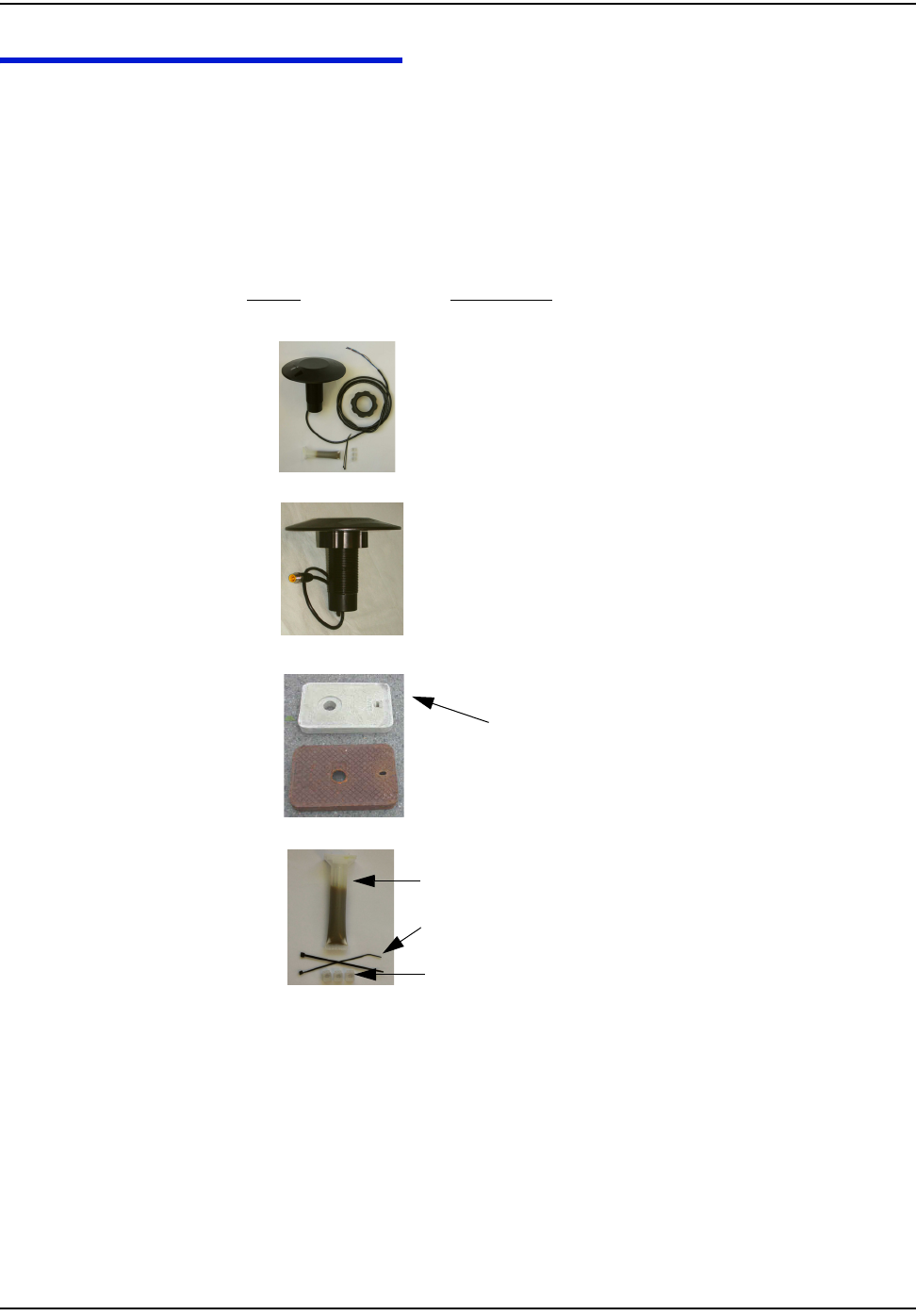
The following table contains all required equipment:
Image Description
`ÉääåÉí=t~íÉê=båÇéçáåí=jçÇÉä=SMNM=J=máí=ïáíÜ=iÉ~ÇëI=páåÖäÉ=
mçêí
lo
`ÉääåÉí=t~íÉê=båÇéçáåí=jçÇÉä=SMOMJmáíI=ïáíÜ=ÅçååÉÅíçêI=ïáíÜ=
ëìÄãÉêëáÄäÉ=ÅçååÉÅíçê
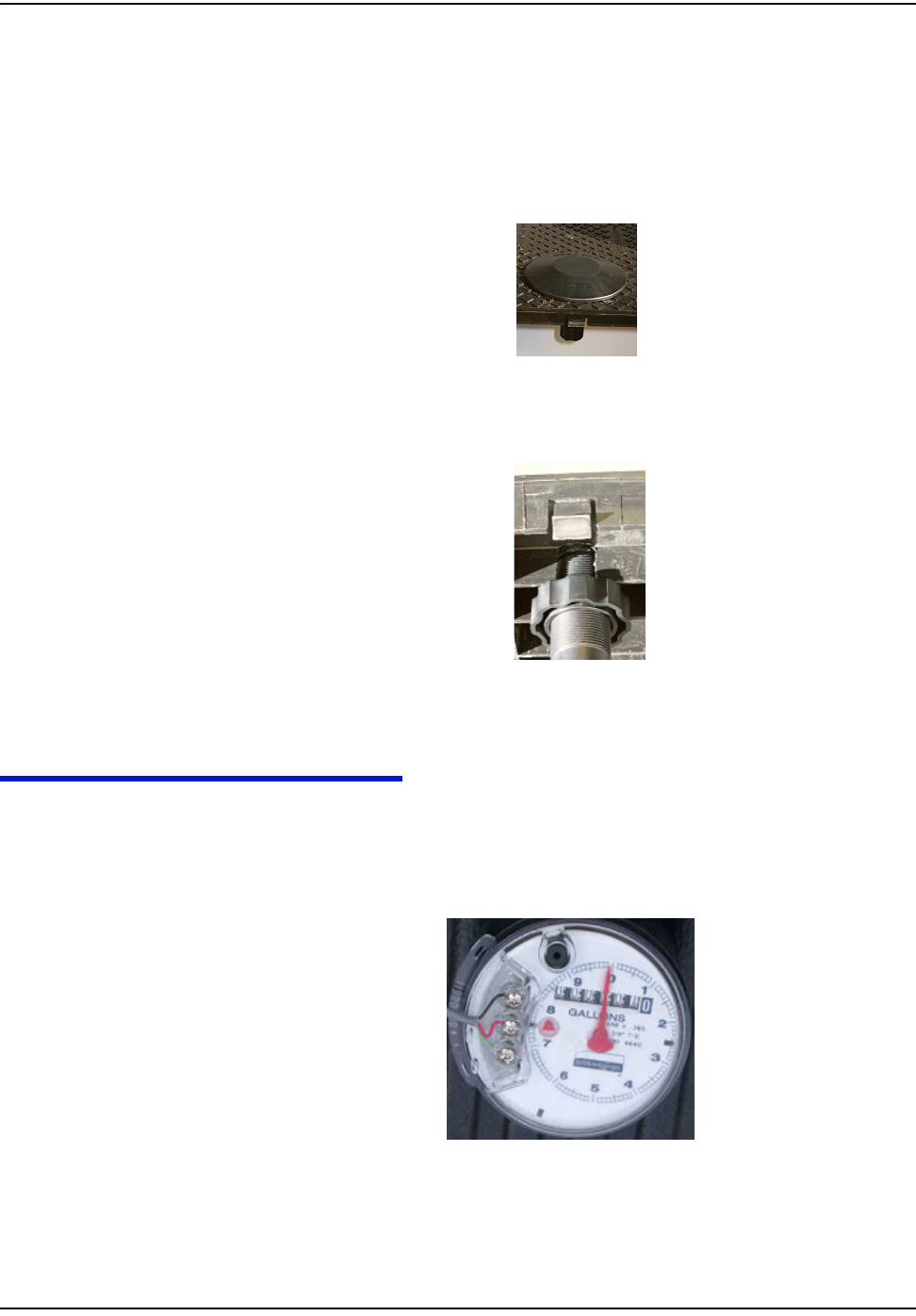
máí=iáÇë
NOTE: A pit lid with a recessed antenna hole to flush-mount the
antenna is recommended, particularly for the street or
sidewalk, shown here a polymer lid with a recessed hole.
_~ÇÖÉê=cáÉäÇ=péäáÅÉ=háí=SOMUQJMMN
image ëÅçíÅÜäçâ
image dÉä=ëÉ~ä~åí=êÉãçîÉê
Polymer
Metal
péäáÅÉ=båÅäçëìêÉ
qáÉ=ïê~éë
Pj=pÅçíÅÜäçâëI=jçÇÉä=rvO=çê=bèìáî~äÉåí

fåíêçÇìÅíáçå
`ÉääåÉí=t~íÉê=båÇéçáåí=fåëí~ää~íáçå=dìáÇÉ NJP
^ÇÇáíáçå~ä=Å~ÄäÉ
péÉÅáÑáÅ~íáçå=OOJ^tdKKK
Image Description
NJQ `ÉääåÉí=t~íÉê=båÇéçáåí=fåëí~ää~íáçå=dìáÇÉ
fåíêçÇìÅíáçå
Tools
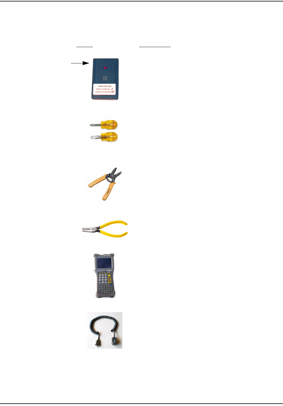
The following table contains all required tools:
Image Description
oc=_ìëíÉê
mLk=OSJNMRM
pÅêÉïÇêáîÉêë=EÑä~í=~åÇ=mÜáääáéëF
táêÉ=`ìííÉê=~åÇ=píêáééÉê
pÅçíÅÜäçâ®=bJVv=`êáãéáåÖ=qççä=çê=bèìáî~äÉåí
ïïïKPjKÅçã
a^m=e~åÇeÉäÇ=`çãéìíÉê=
ïïïKÇ~éKÅçã
jáÅêçíÉñ=c~ëíêÉ~ÇÉê=mêçÄÉ
mLk=coNiJa^mJNU
ïïïKãáÅêçíÉñKÅçã
j~ÖåÉí
fåíêçÇìÅíáçå
`ÉääåÉí=t~íÉê=båÇéçáåí=fåëí~ää~íáçå=dìáÇÉ NJR
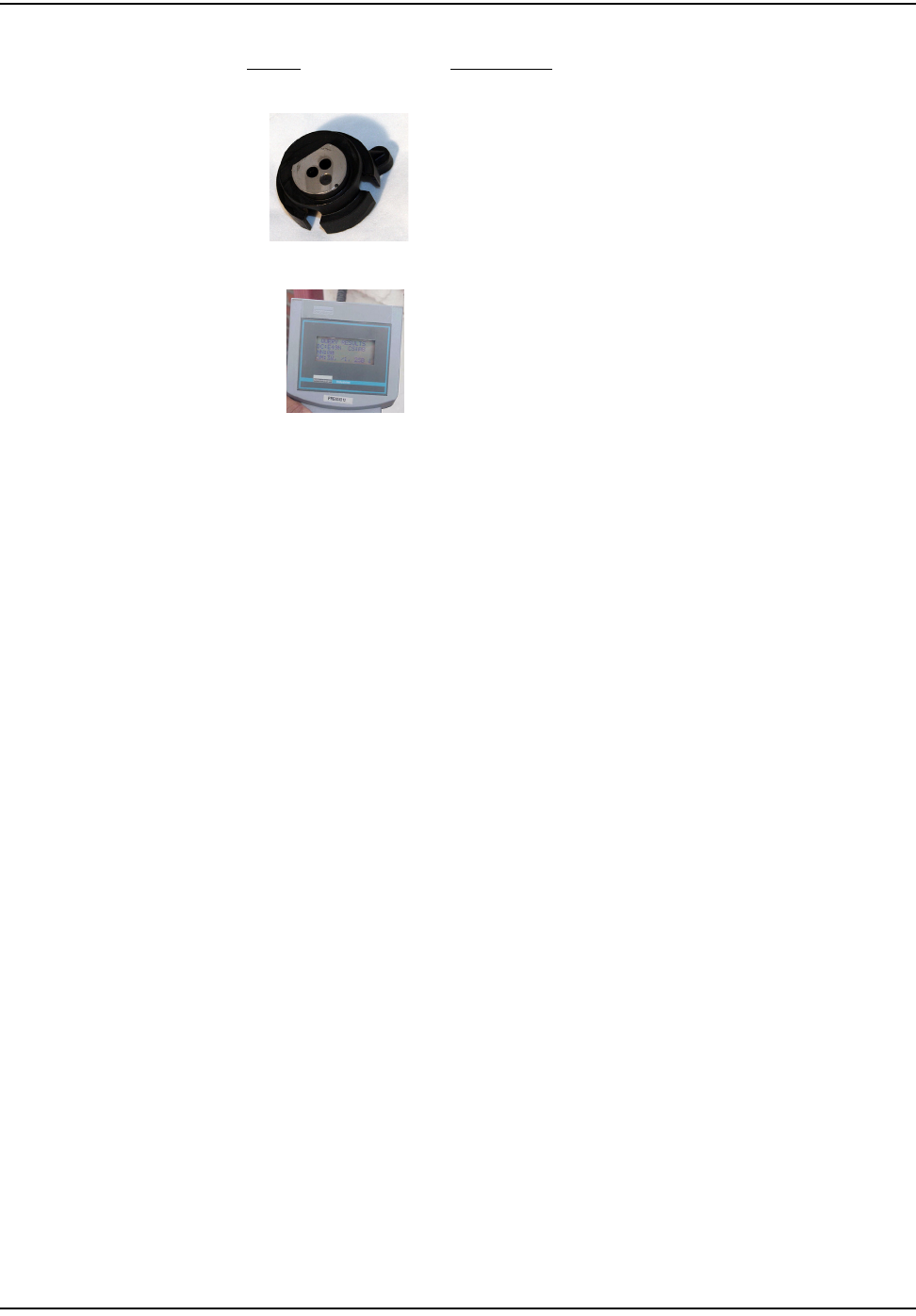
léíáÅ~ä=mêçÄÉ=^Ç~éíÉê=Eléíáçå~äF
mêçoÉ~Ç=cáÉäÇ=mêçÖê~ããÉê=Eçåäó=êÉèìáêÉÇ=Ñçê=kÉéíìåÉ=
ÉåÅçÇÉêëF
ïïïKåÉéíìåÉíÖKÅçã
Image Description

fåíêçÇìÅíáçå
NJS `ÉääåÉí=t~íÉê=båÇéçáåí=fåëí~ää~íáçå=dìáÇÉ
SAFETY AND ENVIRONMENT
Preliminary Checks
The installer should already be able to operate the DAP handheld computer.
Additionally, you should already have route information and the required
number of endpoints.
• Verify that you are at the correct site, specified on the handheld computer or
work order.
• Verify that the site is safe for you and your equipment.
• Notify the customer of your presence. Tell the customer that you must have
access to the water meter. If necessary, have the customer sign the work order.
• When installing meters, follow any guidelines issued by your company in
addition to those given in this guide.
• Never perform an installation during a lightning storm or under excessively
wet conditions.
Site Requirements
The site must comply with the following criteria:
• There is no chance that another object will be set over the antenna.
• There is enough room in the pit for the endpoint. Because the meter position
is fixed, the antenna is usually installed off-center.
• The pit is not flooded; it is debris free.
• The endpoint has an attached cable, but in some instances it may require
additional cable. The maximum cable length between the encoder register
and the endpoint depends on the register's manufacturer and model.
Table 1.1, lists maximum cable lengths, meeting the manufacturer’s published
specification for wire length between encoder and remote receptacle.
Table 1.1
Encoder Register Maximum Cable Length
_~ÇÖÉê=^ab OMM=ÑÉÉí=ESN=ãÉíÉêëF
_~ÇÖÉê=oqo OMM=ÑÉÉí=ESN=ãÉíÉêëF
kÉéíìåÉ=mêçoÉ~Ç=E^o_=sfF OMM=ÑÉÉí=ESN=ãÉíÉêëF
pÉåëìë=b`oJff OMM=ÑÉÉí=ESN=ãÉíÉêëF
pÉåëìë=b`oJfff OMM=ÑÉÉí=ESN=ãÉíÉêëF
fåíêçÇìÅíáçå
`ÉääåÉí=t~íÉê=båÇéçáåí=fåëí~ää~íáçå=dìáÇÉ NJT
FCC & INDUSTRY CANADA INFORMATION TO THE USER
FCC Class B
This equipment has been tested and found to comply with the limits for a Class B
digital device, pursuant to Part 15 of the FCC Rules. These limits are designed to
provide reasonable protection against harmful interference in a residential
installation. This equipment generates, uses, and can radiate radio frequency
energy and, if not installed and used in accordance with the Instructions, may
cause harmful interference to radio communications. However, there is no
guarantee that interference will not occur in a particular installation. If this
equipment does cause harmful interference to radio or television reception, which
can be determined by turning the equipment off and on, the user is encouraged to
try to correct the interference by one or more of the following measures:
• Reorient or relocate the receiving antenna.
• Increase the separation between the equipment and receiver.
• Connect the equipment into an outlet on a circuit different from that to which
the receiver is connected.
• Consult the dealer or an experienced radio/TV technician for help.
RF Exposure
In accordance with FCC requirements of human exposure to radio frequency
fields, the radiating element shall be installed such that a minimum separation
distance of 20 centimeters will be maintained.
Industry Canada
This Class B digital apparatus meets all requirements of the Canadian
Interference Causing Equipment Regulations. Operation is subject to the
following two conditions: (1) this device may not cause harmful interference, and
(2) this device must accept any interference received, including interference that
may cause undesired operation.
Cet appareillage numérique de la classe B répond à toutes les exigences de
l'interférence canadienne causant des règlements d'équipement. L'opération est
sujette aux deux conditions suivantes: (1) ce dispositif peut ne pas causer
l'interférence nocive, et (2) ce dispositif doit accepter n'importe quelle interférence
reçue, y compris l'interférence qui peut causer l'opération peu désirée.
Changes or modifications to this device not expressly approved by Cellnet
Technology, Inc. could void the user's authority to operate the equipment.

fåíêçÇìÅíáçå
NJU `ÉääåÉí=t~íÉê=båÇéçáåí=fåëí~ää~íáçå=dìáÇÉ
FCC ID: R7PUWE-PIT
This device complies with Part 15 of the FCC rules. Operation is subject to the
following two conditions:
(1) This device may not cause harmful interference, and
(2) This device must accept any interference received, including interference that
may cause undesired operation.
IC: 5294A-UWEPIT
This Class B digital apparatus complies with Canadian ICES-003.
Cet appareil numérique de la classe B est conforme à la norme NMB-003 du
Canada.
tOMNM=máí=jfr=fåëí~ää~íáçå OJN
CHAPTER 2 INSTALLING THE CELLNET WATER ENDPOINT
If the meter register inside the pit is pre-potted with a 'Cellnet 6020 ready'
submersible cable, and reusable, female 4-pin connector on its open end, proceed
to "Installing Cellnet Water Endpoint 6020 Pit on a "Cellnet 6020 ready" Register" on
page 2-16.
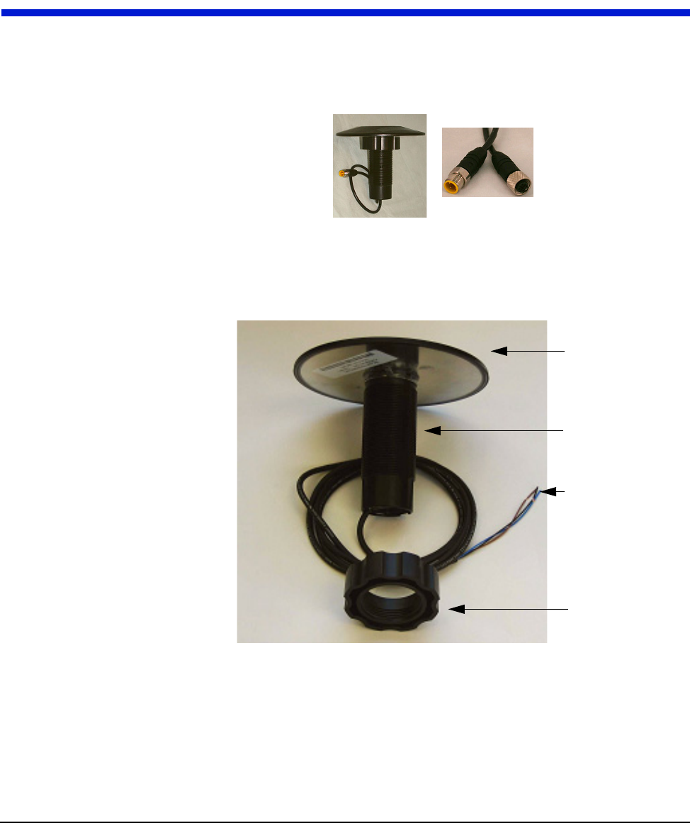
Figure 2.1 6020 Endpoint with a water submersible, reusable, female 4-pin connector
All other registers use:
Figure 2.2 6010 Pit Endpoint exploded view
Callouts indicate the assembly parts.
^åíÉåå~
qìÄÉ=båÅäçëìêÉ
píêáééÉÇ=~åÇ=oÉí~áåÉÇ=
iÉ~Ç
jçìåíáåÖ=kìí
fåëí~ääáåÖ=íÜÉ=`ÉääåÉí=t~íÉê=båÇéçáåí
OJO tOMNM=máí=jfr=fåëí~ää~íáçå
Installing the 6010 Endpoint
1 Unscrew the nut from the 6010 endpoint. Reserve it for later.
2 Route the endpoint (attached cable first) through the antenna hole in the pit
lid from the top.
Certain installations may require you to remove the existing touchpad from
the antenna hole before you can insert the antenna.Verify that there is enough
room in the pit for the endpoint, and that the cable is long enough.
Figure 2.3 Antenna hole in pit lid
3 Thread the nut to the top of the antenna, tightening it against the bottom of
the pit lid.
Figure 2.4 Threading the antenna nut
4 Put the pit lid with the 6010 endpoint aside for later.
IDENTIFYING THE REGISTER FOR INSTALLATION
Register connecting instructions listed by register type:
• If the register has screw terminals, proceed to "Connecting a Neptune or Sensus
Encoder Register with Screw Terminals" on page 2-4
update photo
fåëí~ääáåÖ=íÜÉ=`ÉääåÉí=t~íÉê=båÇéçáåí
tOMNM=máí=jfr=fåëí~ää~íáçå OJP
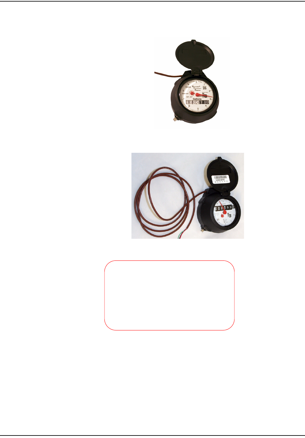
• If the register is a badger RTR with the words “Recordall Transmitter
Register” recorded on the face, proceed to"Connecting a Badger RTR Register
with Potted Leads" on page 2-11
• If the register is not a Badger RTR and has potted leads, proceed to
"Connecting a Badger, Neptune or Sensus Encoder Register with Potted Leads" on
page 2-6
•"Pro-Read Encoder Register" on page 2-17
photo
OJQ tOMNM=máí=jfr=fåëí~ää~íáçå
fåëí~ääáåÖ=íÜÉ=`ÉääåÉí=t~íÉê=båÇéçáåí
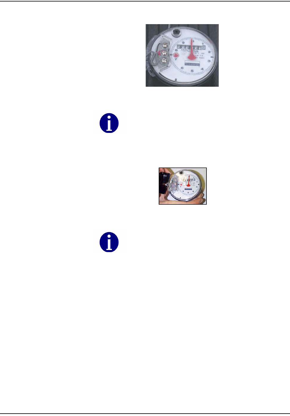
Connecting a Neptune or Sensus Encoder Register with Screw Terminals
Remove terminal cover. Use a manufacturer-approved gel sealant remover on the
terminals to remove gel from existing encoder installations before connecting the
6010 cable to the screws. Use clean, disposable towels or rags to wipe the gel
away from the terminals and screws. After the gel is removed, disconnect any
wires connected to the terminals. Clean the terminals and screws again. Be careful
not to lose any screws when disconnecting the wires or cleaning the screw
terminals.
If the cable to be connected to the screw terminals has been pre-stripped, proceed
to step 3 below.
1 Using the #10 AWG position (second largest hole) on the 64-1919 wire
stripper, remove 1.5 inches of external insulation from the cable coming from
the 6010.
Figure 2.5 64-1919 Wire stripper
2 Using the #22 AWG wire-stripping hole of 64-1922 tool, strip .5 inch of
insulation from each of the three internal wires.
Figure 2.6 64-1922 Wire stripper
3 Connect the three-conductor wire from the 6010 endpoint to the encoder
register's terminals, matching colors carefully, using the following table.
Do not damage the internal wire insulation when removing the
external insulation.
Table 1
Encoder Register 6010 Wire Color/Encoder Terminal
Neptune ProRead (ARB
VI)
pic with proper config of wires
Blk/G Green/R Red/B
Sensus ECR-II, ECR-III
(ICE)
pic with proper config of wires
Blk/B Green/G Red/R
fåëí~ääáåÖ=íÜÉ=`ÉääåÉí=t~íÉê=båÇéçáåí
tOMNM=máí=jfr=fåëí~ää~íáçå OJR
4 Thread the cable around the strain relief posts of the encoder register.
Figure 2.7 Threading the cable around the strain relief posts
5 Apply moisture protection compound to terminal screws and exposed wires
(Dow Corning Compound #4 or Novagard® G661™)
Figure 2.8 Applying moisture compound
6 Snap the cover onto the encoder register.
7 Wipe away excess compound.
8 Clean the area and remove all disposable materials.
9 Proceed to Chapter 3, Testing the Endpoint.
Position the end of the cable jacket so that the compound will cover
it and it will not be visible when the cover is installed, as shown.
Be sure that the waterproofing compound completely seals the wires.
Apply compound under the cable and individual wires. Cover the top of the
cable, wires, and screws. Use enough compound so it flows from
openings when the cover is attached.
fåëí~ääáåÖ=íÜÉ=`ÉääåÉí=t~íÉê=båÇéçáåí
OJS tOMNM=máí=jfr=fåëí~ää~íáçå
Connecting a Badger, Neptune or Sensus Encoder Register with Potted Leads
Use the following installation procedure for sites equipped with potted encoders.
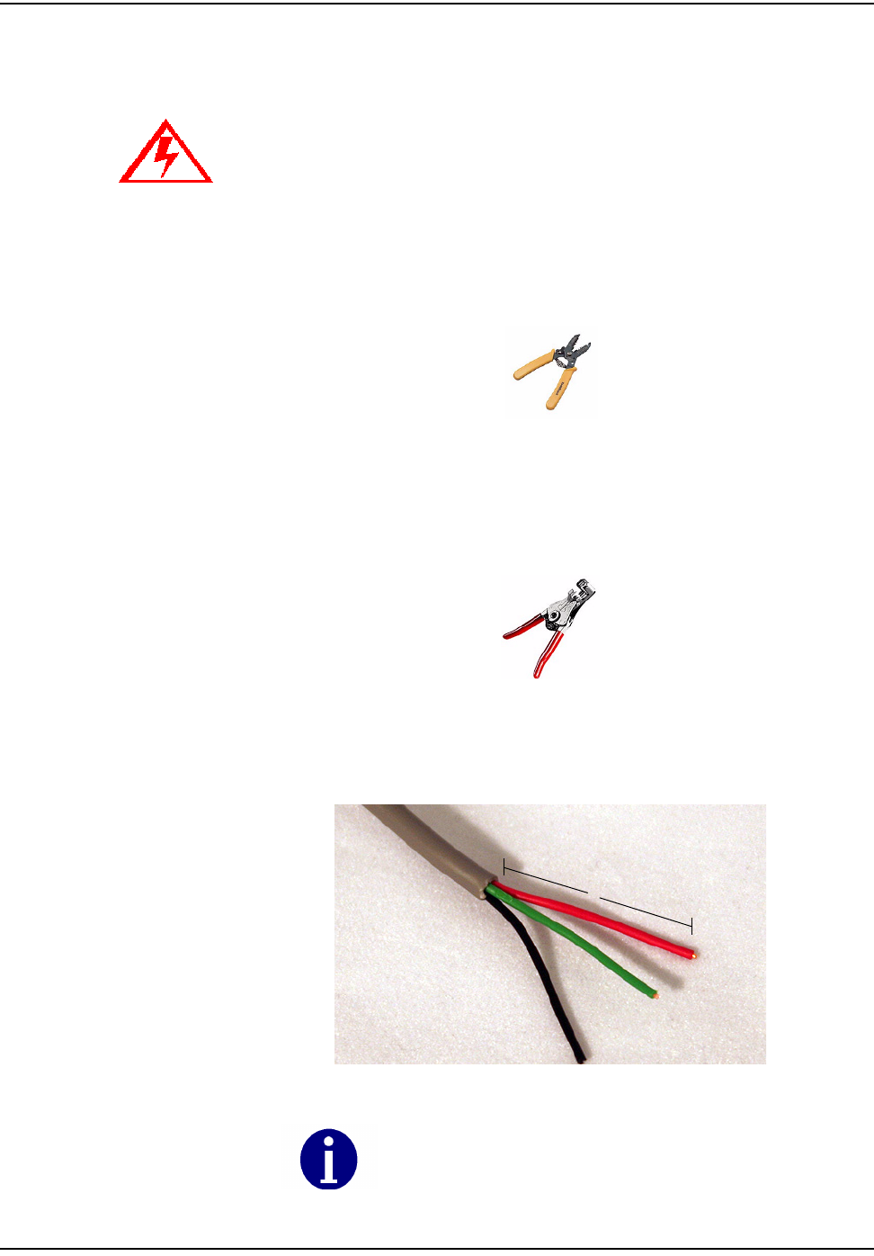
1 Using the cutting blade portion of the Wire Cutter and Stripper tool, cut the
wire connecting the encoder register to the touchpad (or other device). The
wire attached to the encoder register should contain at least three wires. If
not, replace the encoder register with a 3-wire version.
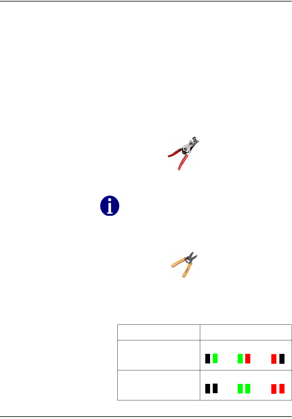
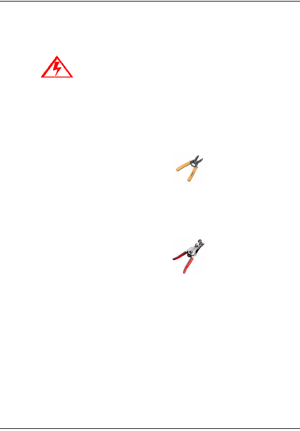
Figure 2.9 Wire cutter & stripper
2 Using the #10 AWG position (second largest hole) on the 64-1919 wire
stripper, remove 1 inch of the external insulation from the cable coming from
the encoder register. Do not strip the insulation from the internal wires.
Figure 2.10 64-1919 Wire Stripper
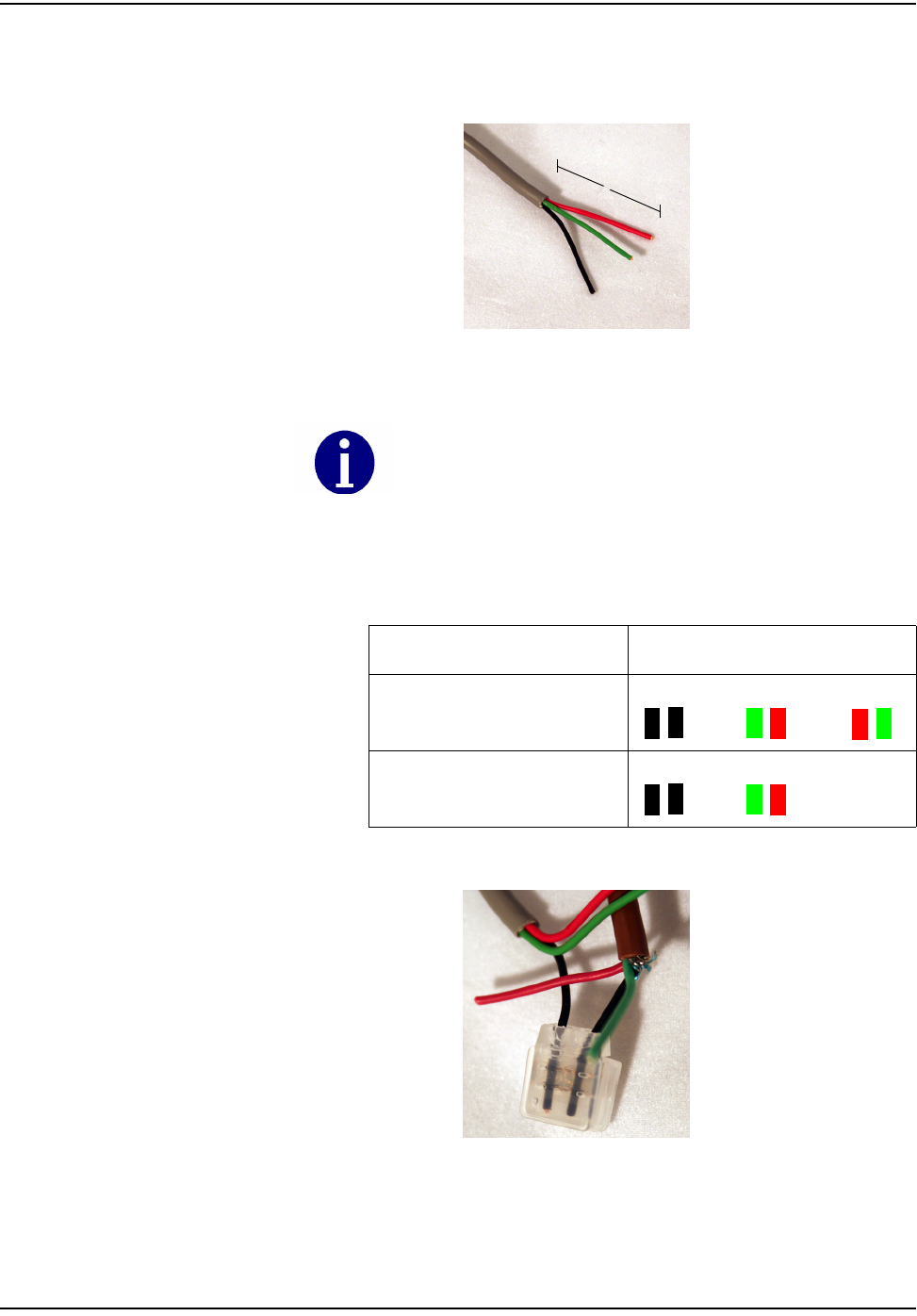
3 Peel back foil, if present; cut excess foil and uninsulated wire.
4 Repeat this procedure for the cable coming from the 6010 endpoint, if
necessary.
Figure 2.11 3-Wire cable
Do not open a potted encoder for any reason. This will void the manufacturer’s
warranty.
Do not damage the internal wire insulation when removing the external
insulation.
1”
fåëí~ääáåÖ=íÜÉ=`ÉääåÉí=t~íÉê=båÇéçáåí
tOMNM=máí=jfr=fåëí~ää~íáçå OJT
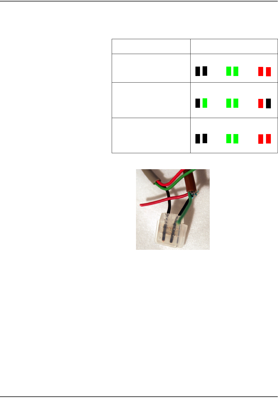
5 Splice the wires from the UWE to the encoder wires. Match colors carefully
according to the table below:
6 Push the wires to be connected as far as possible into the Scotchlok connector.
Figure 2.12 Wires pushed into Scotchlok connector
Table 2
Encoder Register 6010 Wire Color/Encoder Terminal
Badger ADE
pic with proper config of wires Blk/Blk Green/Green Red/Red
Neptune ProRead (ARB
VI)
pic with proper config of wires
Blk/Grn Green/Green Red/Blk
Sensus ECR-II, ECR-III
(ICE)
pic with proper config of wires
Blk/Blk Green/Green Red/Red

fåëí~ääáåÖ=íÜÉ=`ÉääåÉí=t~íÉê=båÇéçáåí
OJU tOMNM=máí=jfr=fåëí~ää~íáçå
7 Place the Scotchlok connector (with wires) into the jaws of the crimping tool.
Figure 2.13 ScotchLok connector in crimping tool jaws
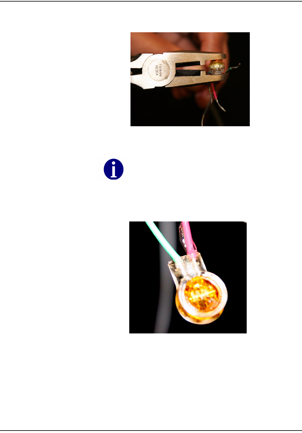
8 Crimp the Scotchlok connector by squeezing the handles until it discharges
gel. Continue to apply pressure for three seconds..
Figure 2.14 Crimped Scotchloks discharge gel
Always use 3M Parallel Jaw Crimping Tool 3M Model E-
9Y or equivalent.
fåëí~ääáåÖ=íÜÉ=`ÉääåÉí=t~íÉê=båÇéçáåí
tOMNM=máí=jfr=fåëí~ää~íáçå OJV
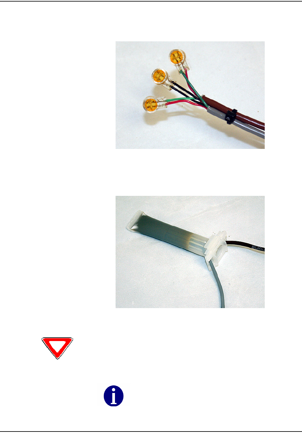
9 Place two plastic cable ties on wires and tighten securely for strain relief.
Remove excess cable tie with wire cutters..
Figure 2.15 Placing plastic ties on cables
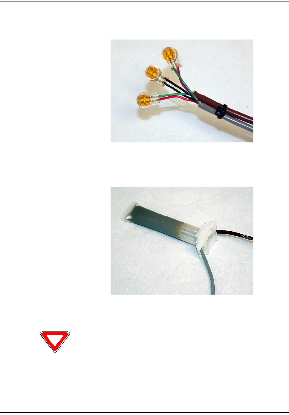
10 Insert the entire splice assembly into the silicone-filled splice enclosure. Close
the cover with leads exiting alternate sides
Figure 2.16 Inserting splice assembly into silicone-filled splice enclosure
Cellnet strongly recommends a splice enclosure, particularly for Badger RTR
installations. Failure to use a splice enclosure may invalidate the manufacturer’s
warranty.
The 3M Gel splice connector is NOT reusable. Replace the splice if
necessary.
match up wires with above

fåëí~ääáåÖ=íÜÉ=`ÉääåÉí=t~íÉê=båÇéçáåí
tOMNM=máí=jfr=fåëí~ää~íáçå OJNN
Connecting a Badger RTR Register with Potted Leads
Badger manufactures "potted" RTR registers for water meter applications. These
registers have a three-conductor cable already attached to the register. The factory
seals them with a "potting compound".
Use the following installation procedure for sites equipped with potted RTR
registers.
1 Using the cutting blade portion of the Wire Cutter and Stripper tool, cut the
wire connecting the encoder register to the touchpad (or other device). The
wire attached to the encoder register should contain at least three wires. If
not, replace the encoder register with a 3-wire version.
Figure 2.17 Wire cutter & stripper
2 Using the #10 AWG position (second largest hole) on the 64-1919 wire
stripper, remove 1 inch of the external insulation from the cable coming from
the encoder register. Do not strip the insulation from the internal wires.
Figure 2.18 64-1919 Wirestripper
3 Peel back foil, if present. Cut excess foil and uninsulated wire.
Do not open a potted encoder for any reason. This will void the manufacturer’s
warranty.
correct wire color config
fåëí~ääáåÖ=íÜÉ=`ÉääåÉí=t~íÉê=båÇéçáåí
OJNO tOMNM=máí=jfr=fåëí~ää~íáçå
4 Repeat this procedure for the cable coming from the 6010 endpoint, if
necessary.
Figure 2.19 3-Wire cable
5 Splice wires from UWE to Badger RTR. Match colors carefully according to
the table below.
6 Push the wires to be connected as far as possible into the Scotchlok connector.
Figure 2.20 Wires inserted into Scotchlok connector
Do not damage the internal wire insulation when removing the external
insulation.
Table 3
Encoder Register 6010 Wire Color/Encoder Terminal
Badger RTR 3-Wire Blk/Blk Green/Red Red/Green
_~ÇÖÉê=oqo=OJtáêÉ Blk/Blk Green/Red
1”
photo
fåëí~ääáåÖ=íÜÉ=`ÉääåÉí=t~íÉê=båÇéçáåí
tOMNM=máí=jfr=fåëí~ää~íáçå OJNP
7 Place the Scotchlok connector (with wires) into the jaws of the crimping tool.
Figure 2.21 ScotchLok connector in crimping tool jaws
8 Crimp the Scotchlok connector by squeezing the handles until it discharges
gel. Continue to apply pressure for three seconds..
Figure 2.22 Crimped Scotchloks discharge gel
Always use 3M Parallel Jaw Crimping Tool 3M Model E-
9Y or equivalent.
match wire colors
fåëí~ääáåÖ=íÜÉ=`ÉääåÉí=t~íÉê=båÇéçáåí
OJNQ tOMNM=máí=jfr=fåëí~ää~íáçå
9 Place two plastic cable ties on wires and tighten securely for strain relief.
Remove excess cable tie with wire cutters..
Figure 2.23 Placing plastic ties on cables
10 Insert the entire splice assembly into the silicone-filled splice enclosure. Close
the cover with leads exiting alternate sides
Figure 2.24 Inserting splice assembly into silicone-filled splice enclosure
Cellnet strongly recommends a splice enclosure, particularly for Badger RTR
installations. Failure to use a splice enclosure may invalidate the manufacturer’s
warranty.
fåëí~ääáåÖ=íÜÉ=`ÉääåÉí=t~íÉê=båÇéçáåí
tOMNM=máí=jfr=fåëí~ää~íáçå OJNR
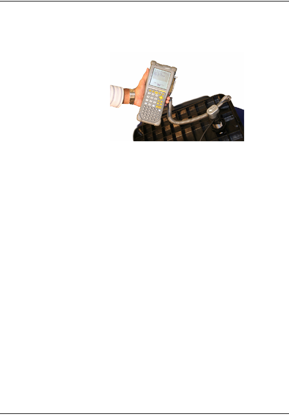
Programming 6010 endpoint for operation with a Badger RTR Register
You must program the 6010 endpoint with the DAP HandHeld computer before it
can operate with a Badger RTR register. Connect the MicroTex Fastreader Probe
to the DAP HandHeld as shown below
Figure 2.25 MicrTex Fastreader connected to DAP HandHeld
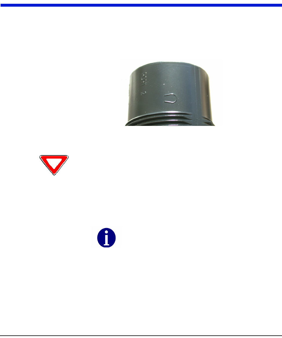
1 Place the optic probe adaptor over the top of the 6010 endpoint tube, using
the keyed slot. Align the magnet tab on the optic adapter with the horseshoe
shaped magnet symbol on the housing.
2 Attach the Microtex Fastreader Probe optic head to the optic probe adapter.
3 Ensure that the Microtex Fastreader Probe is properly connected to the
HandHeld LEMO connector.
4 Follow the HandHeld computer prompts to program the endpoint.
5 Once the programming is complete, proceed to Chapter 3, Testing the Endpoint.
fåëí~ääáåÖ=íÜÉ=`ÉääåÉí=t~íÉê=båÇéçáåí
OJNS tOMNM=máí=jfr=fåëí~ää~íáçå
INSTALLING CELLNET WATER ENDPOINT 6020 PIT ON A "CELLNET 6020 READY"
REGISTER
1 Unscrew the mounting nut from the 6020 endpoint. Reserve it for later.
2 Route the endpoint (attached cable first) through the antenna hole in the pit
lid from top.
Certain installations may require you to remove the existing touchpad from
the antenna hole before you can insert the antenna.
3 Pull the cable through the hole.
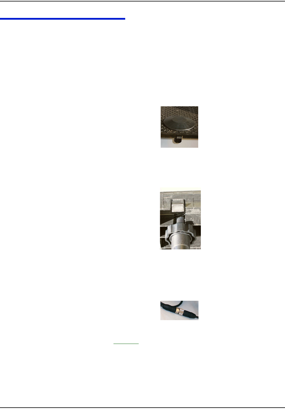
4 Insert the antenna into the antenna hole, flush with the top surface of the pit
lid.
Figure 2.26 Antenna hole in pit lid
5 Verify that there is enough room in the pit for the endpoint, and that the cable
is long enough. Thread the nut to the top of the antenna, tightening it against
the bottom of the pit lid.
Figure 2.27 Threading the mounting nut
6 Put the pit lid with the 6020 endpoint aside for later.
7 Bring the mating connector parts (female attached to the register, male
attached to the endpoint) of the water submersible connector together. Align
the keyed connector and tighten the screw until it is snug.
Figure 2.28 Tightening connector screw
8 Proceed to Chapter 3, Testing the Endpoint.
fåëí~ääáåÖ=íÜÉ=`ÉääåÉí=t~íÉê=båÇéçáåí
tOMNM=máí=jfr=fåëí~ää~íáçå OJNT
PRO-READ ENCODER REGISTER
Before removing the ProRead receptable, ensure that the ProRead register is
programmed for three-wire mode.
• If a two-wire conductor cable is connected to a "potted" ProRead encoder
register, replace the register with a three-wire register.
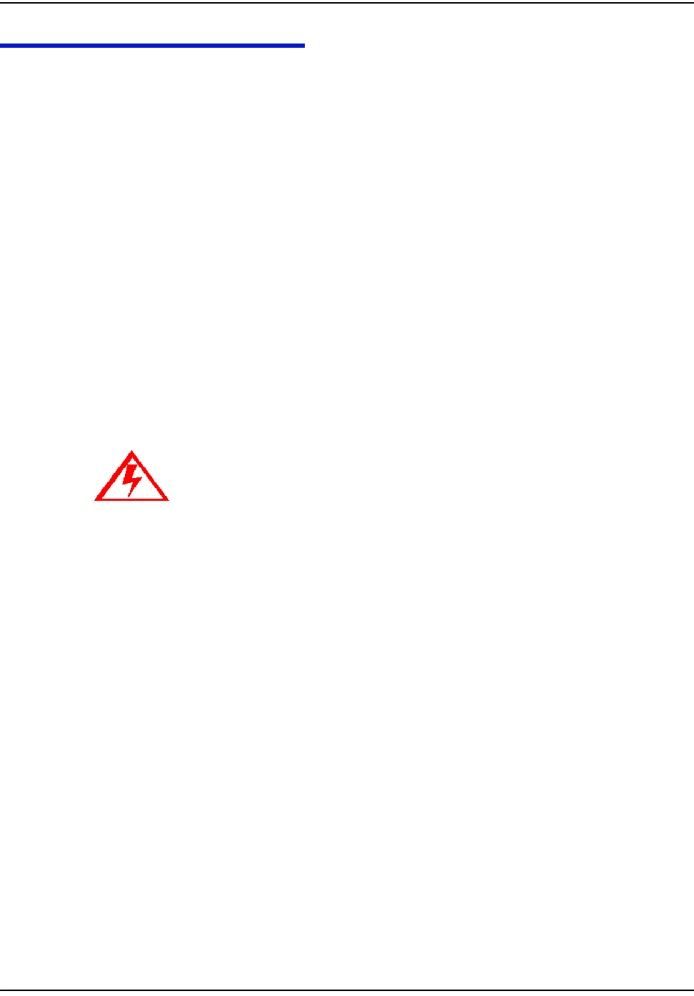
Reprogramming a ProRead encoder from 2-wire to 3-wire
It may sometimes be necessary to reprogram a ProRead register encoder from 2-
wire to 3-wire mode. Accomplish this with a Neptune ProRead field programmer.
A basic overview of the steps is as follows:
1 Connect to the remote receptacle with the field programmer.
2 Interrogate the encoder register to determine its operating mode (2 or 3-wire).
3 Reconfigure the encoder register to make it operate in 3-wire model.
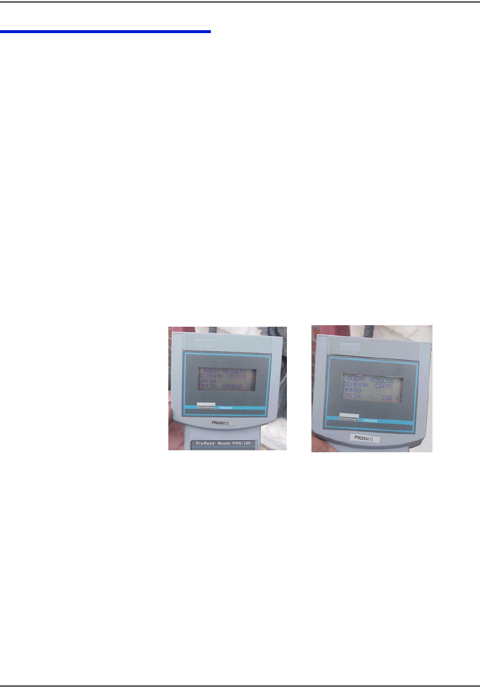
4 Verify that the reconfiguration was successful by looking at the Field
Programmer screen. The OM field should be 3W (see below).
Table 2.1
If the register has screw terminals, proceed to "Connecting a Neptune or Sensus
Encoder Register with Screw Terminals" on page 2-4.
If the register has potted leads, proceed to "Connecting a Badger, Neptune or Sensus
Encoder Register with Potted Leads" on page 2-6.
Before Reprogramming
(2-wire mode)
After Reprogramming
(3-wire mode)

fåëí~ääáåÖ=íÜÉ=`ÉääåÉí=t~íÉê=båÇéçáåí
OJNU tOMNM=máí=jfr=fåëí~ää~íáçå
`ÉääåÉí=t~íÉê=båÇéçáåí=fåëí~ää~íáçå=dìáÇÉ PJN
CHAPTER 3 TESTING THE ENDPOINT
After you have completed the installation process, test the installation by passing
a magnet near the endpoint’s sensor. The CWE tests the connection to the register
and transmits a pattern to indicate if the installation is good or bad. The RF Buster
detects the transmission pattern, beeps and lights the LED.
1 Using the RF Buster, activate the CWE by holding the magnet for less than 1
second against the horseshoe-shaped magnet symbol on the tube housing.
Figure 3.1 Horseshoe Shaped Magnet Symbol
2 Press and hold the button on the RF Buster. Position the RF Buster less than 6
inches away from the top of the CWE. The RF Buster makes audible beeps
and the LED flashes to confirm transmission of an RF packet from the
endpoint.
3 If the RF Buster detects 6-10 packets within 1 minute, the installation is good
and the endpoint has been activated properly. If the RF Buster detects 3 or
fewer packets, it indicates a bad connection between the endpoint and the
register, a bad register, or a bad endpoint. Refer to the troubleshooting section
of this guide to fix the problem.
Caution: If you hold the RF Buster magnet near the endpoint horseshoe magnet sensor for
more than 2 seconds, the endpoint attempts to connect to the DAP Handheld Computer. It
will not transmit the installation test pattern. If you do not hear beeps, hold the RF Buster
away from the CWE for 15 seconds to allow it to reset to normal operating mode.
Do not use a cell phone or any other RF device while conducting
this test.

qÉëíáåÖ=íÜÉ=båÇéçáåí
PJO `ÉääåÉí=t~íÉê=båÇéçáåí=fåëí~ää~íáçå=dìáÇÉ
4 When you are satisfied that the CWE and the register are functioning
correctly, clean up any installation debris.
5 Replace lid onto pit.
6 Double-check that all necessary information is recorded in the handheld.
Proceed to the next location in the route.

`ÉääåÉí=t~íÉê=båÇéçáåí=fåëí~ää~íáçå=dìáÇÉ QJN
CHAPTER 4 ENDPOINT REPLACEMENT
Lift the pit lid and put it aside safely.
If you are replacing a:
•6020
Unscrew and disconnect the submersible connector. Remove the nut that
secures the 6020 the lid. Pull the endpoint out of the antenna hole along with
the attached wires completely.
•6010 connected directly to the encoder register terminals
Remove the terminal cover, loosen screws on terminals, and remove wires.
Loosen the nut that secures the 6010 endpoint to the lid. Pull the endpoint
out of the antenna hole along with the attached wires completely.
•6010 connected with gel splice connectors
Cut off the old splice. Loosen the nut that secures the 6010 endpoint to the lid.
Pull the endpoint out of the antenna hole along with the attached wires
completely.
Proceed to "Identifying the Register for Installation" on page 2-2.

båÇéçáåí=oÉéä~ÅÉãÉåí
QJO `ÉääåÉí=t~íÉê=båÇéçáåí=fåëí~ää~íáçå=dìáÇÉ

`ÉääåÉí=t~íÉê=båÇéçáåí=fåëí~ää~íáçå=dìáÇÉ RJN
CHAPTER 5 TROUBLESHOOTING
What if the register is not compatible with the CWE?
Verify that the register is one of the following:
• Badger ADE
• Badger RTR
• Neptune ProRead (ARB VI)
• Sensus ECR-II
• Sensus ECR-III
If the register is not one of the models listed above, replace with a supported
register type and/or the appropriate meter.
What if the RF Buster does not beep when testing the installation?
Does the RF Buster beep and light the LED when the switch is initially pressed? if
not, the battery in the RF Buster is dead. Replace the RF Buster battery, or use
another RF Buster.
Be careful not to hold the RF Buster magnet near the magnet symbol on the CWE
for more than 1 second.
After activating the magnetic switch on the CWE, hold the RF Buster switch on
continuously. Point the LED end of the RF Buster toward the top of the CWE.
Hold the RF Buster between 6” and 12” from the top of the CWE. Wait 10 seconds.
If the RF Buster does not beep, replace the CWE.
What if the RF Buster does not beep more than 6 times when testing the
installation?
Re-check the manufacturer and model of the register that you are installing. Make
sure you have used the correct color code for that register.
Check the wire between the CWE and the register for cuts, nicks, or broken wires.
Repair or replace the cable if necessary.
If you are using a Pro-read encoder, make sure it is programmed for 3-wire mode.
If you are using a Badger RTR, double-check the programming of the CWE.
If the CWE still does not transmit more than 6 times, replace it.

qêçìÄäÉëÜççíáåÖ
RJO `ÉääåÉí=t~íÉê=båÇéçáåí=fåëí~ää~íáçå=dìáÇÉ
How can I tell the difference between a Sensus ECR-I and ECR-II encoder
register?
The easiest way to determine the difference between ECRI and ECRII is physical
appearance. ECRI is a “high top” design with odometer wheels behind a a flange.
If you still cannot determine which encoder register it is, please contact your local
Sensus Meter Representative.

`ÉääåÉí=t~íÉê=båÇéçáåí=fåëí~ää~íáçå=dìáÇÉ dJN
6010/6020 Cellnet manufactured water endpoint (CWE) - available for pit
installations
MIU Meter Interface Unit
CWE Cellnet Water Endpoint
Register Device used for registering water usage. This can be an Encoder or a
Pulse-counting device
ADE Absolute Digital Encoder
RTR Recordall Transmitter Register
Concentrator Collects all information provided by the Cellnet endpoints.
Pit Cement/metal box containing water meter
PowerLAN Unique network address of endpoints
RF Radio Frequency
Screw terminal Terminal with stripped and retained leads
Potted terminal Terminal with integrated, water submersible, reusable connector
RF Buster Device used to verify RF transmission from endpoint
GLOSSARY

däçëë~êó
dJO `ÉääåÉí=t~íÉê=båÇéçáåí=fåëí~ää~íáçå=dìáÇÉ
Notes:

`ÉääåÉí=t~íÉê=båÇéçáåí=fåëí~ää~íáçå=dìáÇÉ fJN
INDEX
A
^ëëÉãÄäó=é~êíë OJN
B
_~ÇÖÉê=^ab NJS
_~ÇÖÉê=oqo NJS
C
`ÉääåÉí=máí=jfr NJNI=NJO
`ÉääåÉí=máí=jfr=^ëëÉãÄäó NJO
D
a^m=e~åÇeÉäÇ=`çãéìíÉê NJQI=NJS
E
bèìáéãÉåí NJO
N
kÉéíìåÉ=mêçoÉ~Ç=E^o_=sfF NJS
P
máí=iáÇ NJO
mçííÉÇ=ÉåÅçÇÉê NJO
mêçoÉ~Ç=cáÉäÇ=mêçÖê~ããÉê NJR
R
oc=_ìëíÉê NJQ
S
pÅçíÅÜäçâ∆=`êáãéáåÖ=qççä NJQ
pÅêÉï=íÉêãáå~ä=ÉåÅçÇÉê NJO
pÅêÉïÇêáîÉêë NJQ
pÉåëìë=b`oJff NJS
pÉåëìë=b`oJfff NJS
píêáééÉê NJQ
pìÄãÉêëáÄäÉ=Å~ÄäÉ OJN
pìÄãÉêëáÄäÉ=ÅçååÉÅíçê NJO
T
qçç ä ë N J Q
W
táêÉ=`ìííÉê NJQ
INDEX

fJO `ÉääåÉí=t~íÉê=båÇéçáåí=fåëí~ää~íáçå=dìáÇÉ