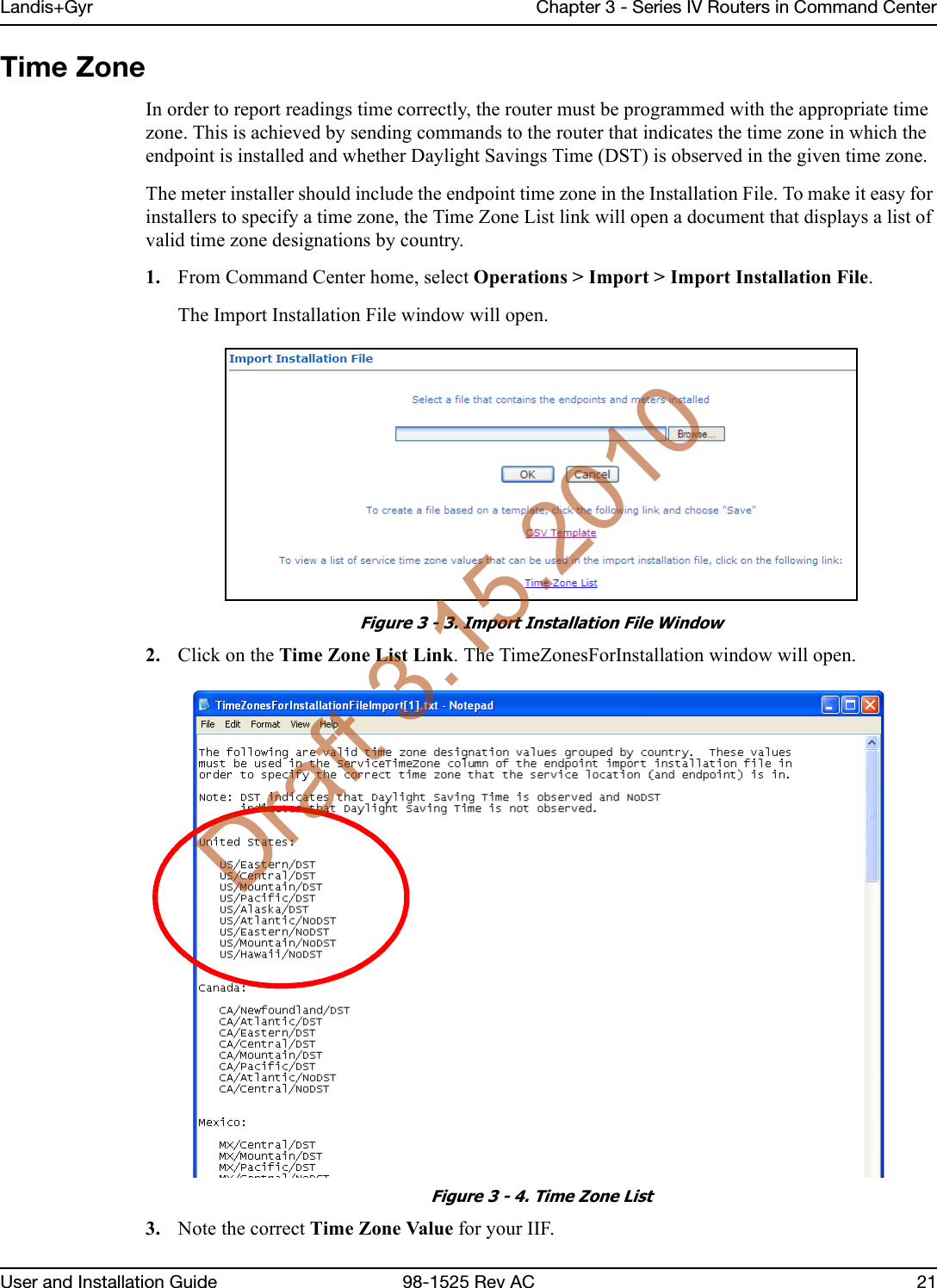
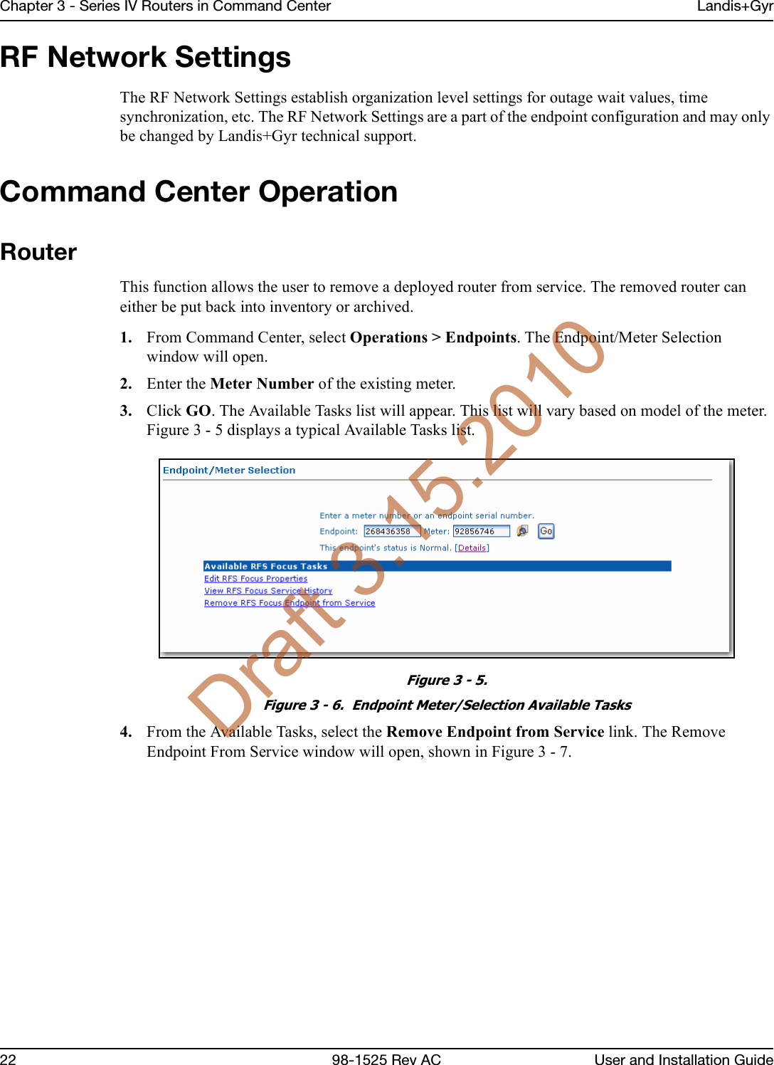
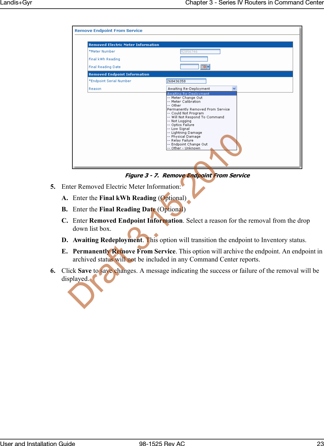
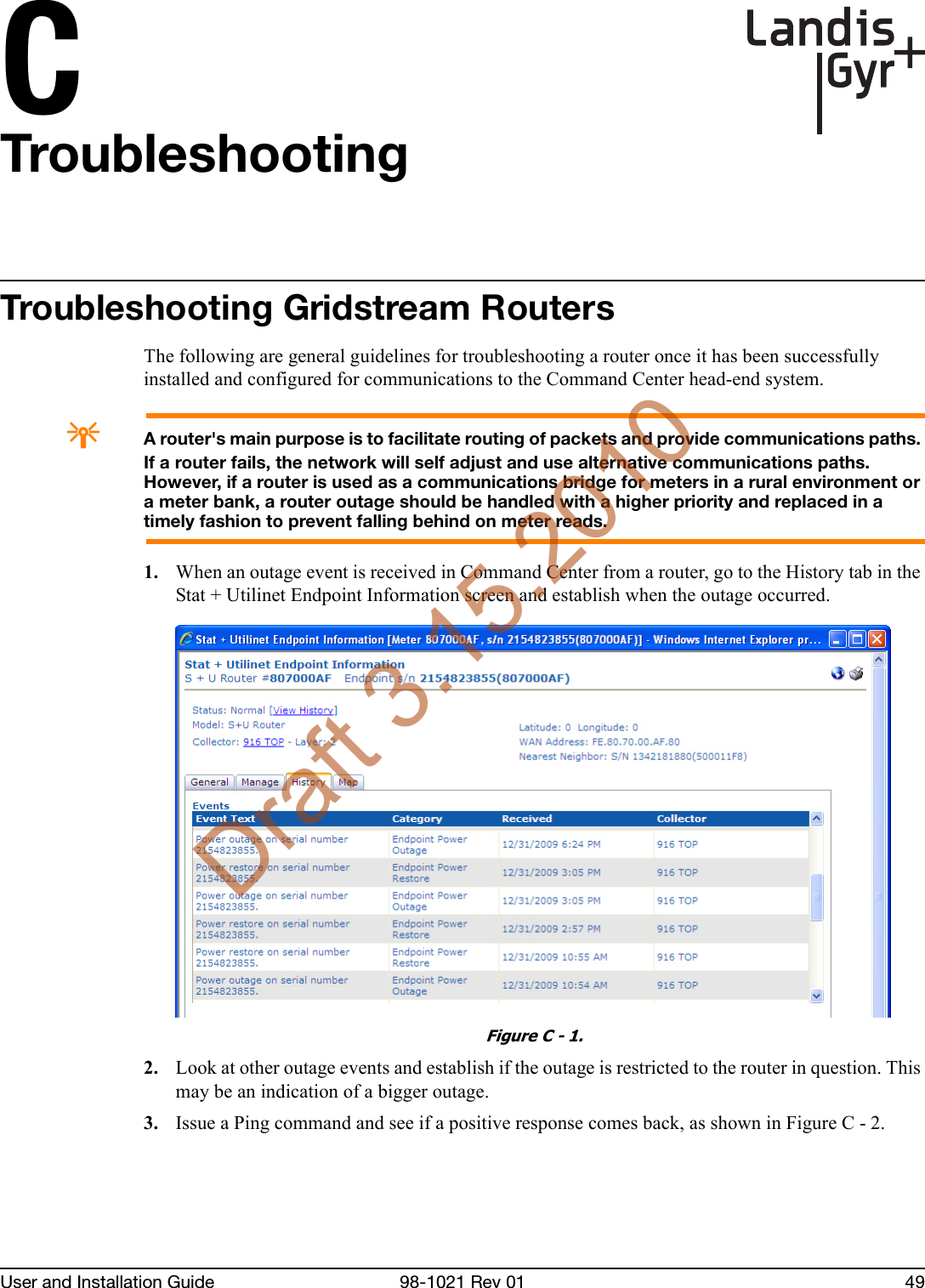
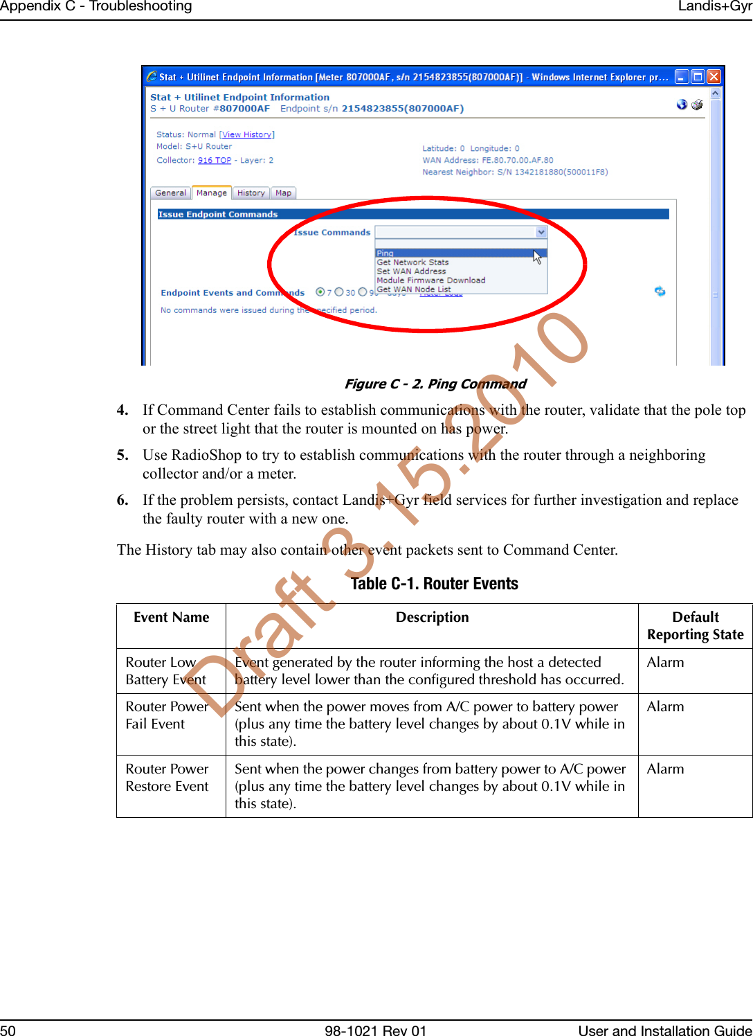
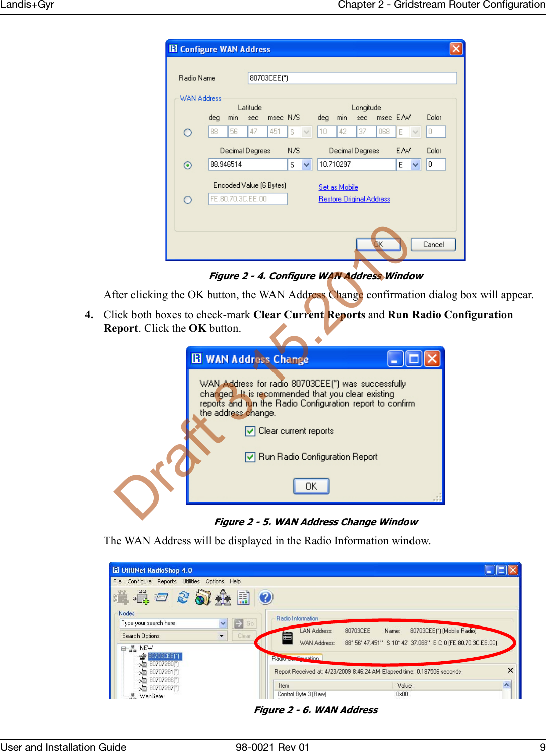
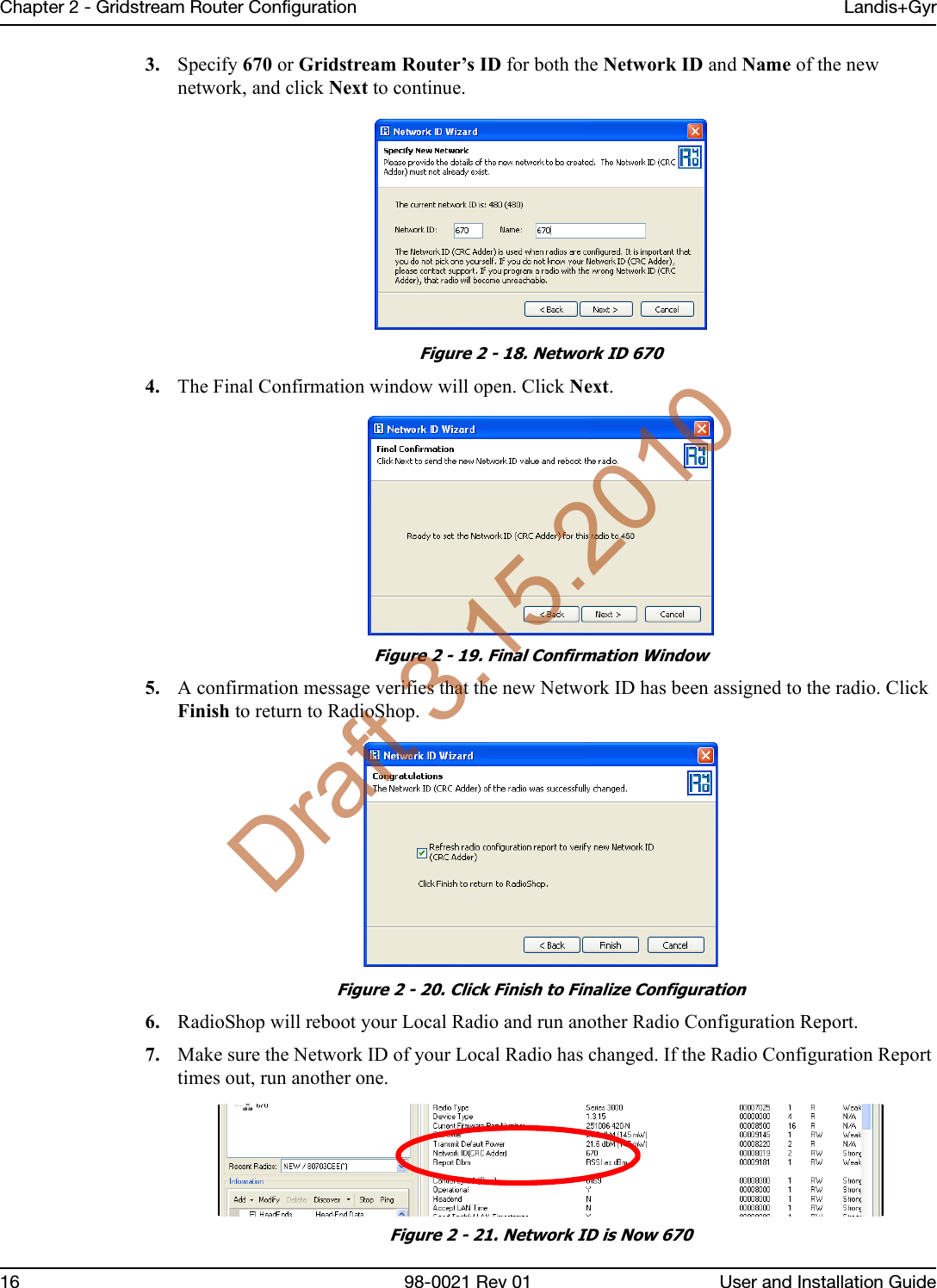
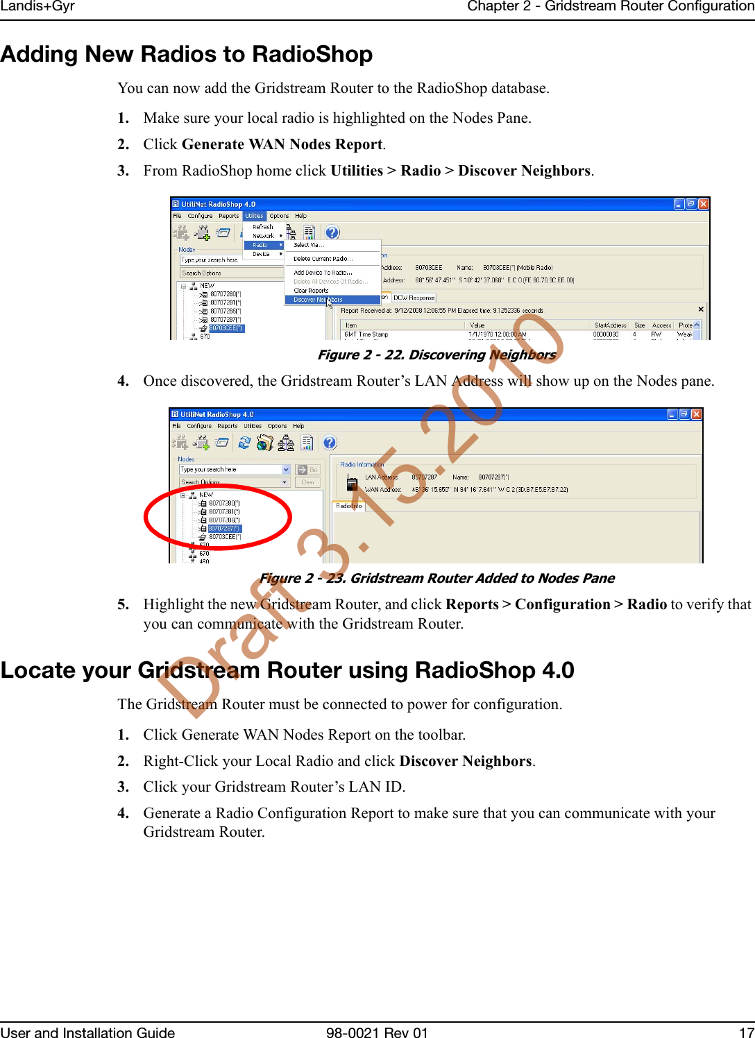
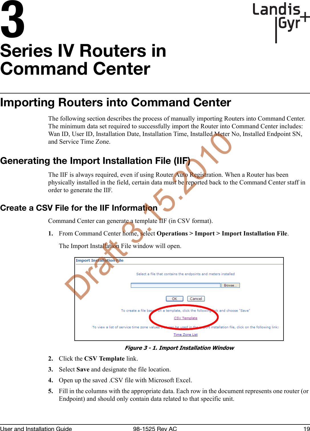
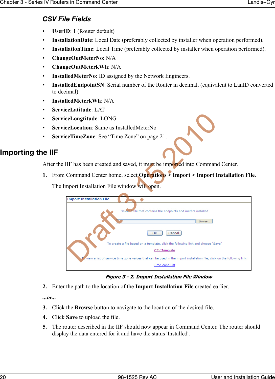
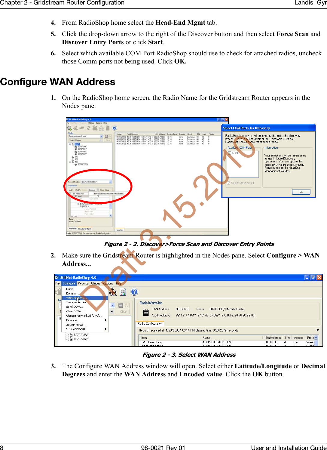
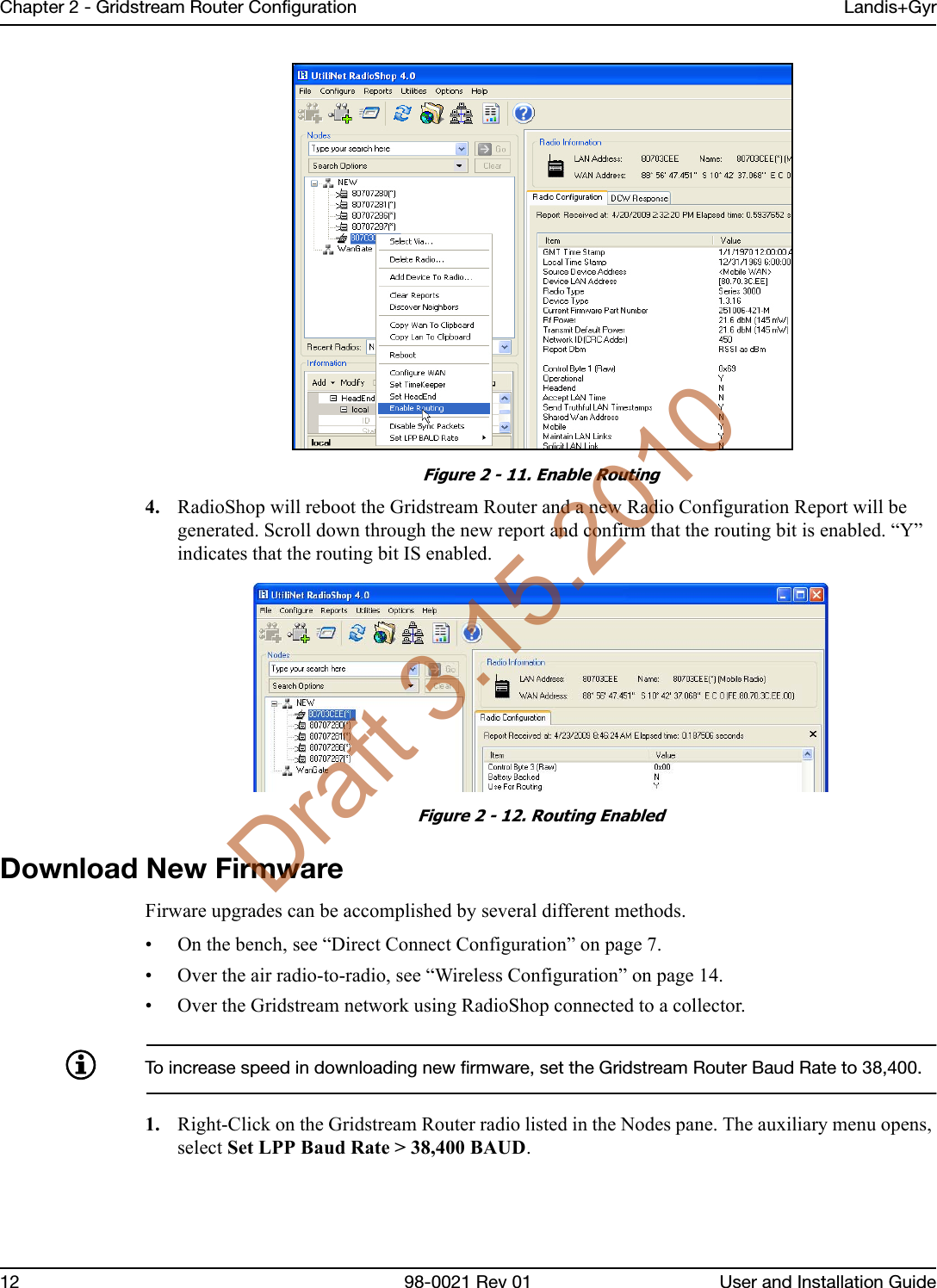
Landis Gyr Technology WGRS4 Gridstream Wangate User Manual XX XXXX Exhibit Cover

Landis+Gyr Technology, Inc. Gridstream Wangate XX XXXX Exhibit Cover

Manual

    5015 B.U. Bowman Drive  Buford, GA 30518 USA Voice: 770-831-8048 Fax: 770-831-8598   Certification Exhibit     FCC ID:  R7PWGRS4  FCC Rule Part: 15.247  ACS Report Number:  09-0421.W03.11.A   Manufacturer: Cellnet Technology, Inc. Model: Gridstream Wangate     Manual
LANDIS+GYR CONFIDENTIAL INFORMATIONLandis+GyrSeries IV Gridstream RF Router User andInstallation GuidePublication: 98-1021 Rev 01Draft 3.15.2010
Limitation on Warranties and LiabilityInformation in this document is subject to change without notice. This manual or any part of it thereof may not be reproduced in any form unless permitted by contract or by written permission of Landis+Gyr.In no event will Landis+Gyr be liable for any incidental, indirect, special, or consequential damages (including lost profits) arising out of or relating to this publication or the information contained in it, even if Landis+Gyr has been advised, knew, or should have known of the possibility of such damages.© 2010 Landis+Gyr, Inc. All Rights Reserved.TrademarksWanGate®, Cellnet®, UtiliNet®, and RadioShop® are registered trademarks of Landis+Gyr.Landis+Gyr Series IV Gridstream RF Router User and Installation GuidePublication: 98-1021 Rev 01Revision HistoryModification Date Revision Description Author3/15/10 01 Work in progress Kim UteschLandis+Gyr6436 County Road 11Pequot Lakes, MN 56472Website: www.landisgyr.comE-mail: solutionsupport.na@landisgyr.comTechnical Support: 1-888-390-5733Copyright© 2010 Landis+Gyr, Inc.All rights reserved.Draft 3.15.2010
User and Installation Guide 98-1021 Rev 01 3Table of ContentsChapter 1:  Gridstream Series IV Router  . . . . . . . . . . . . . . . . . . . . . . . . . . . . . . . . . . . . . . . . . . . . . . . . .  5Overview  . . . . . . . . . . . . . . . . . . . . . . . . . . . . . . . . . . . . . . . . . . . . . . . . . . . . . . . . . . . . . . . . . . . . . . . . . . . . . 5Notes on International version . . . . . . . . . . . . . . . . . . . . . . . . . . . . . . . . . . . . . . . . . . . . . . . . . . . . . . . . . . . . . 6Chapter 2:  Gridstream Router Configuration  . . . . . . . . . . . . . . . . . . . . . . . . . . . . . . . . . . . . . . . . . . . . .  7Direct Connect Configuration  . . . . . . . . . . . . . . . . . . . . . . . . . . . . . . . . . . . . . . . . . . . . . . . . . . . . . . . . . . . . . 7Pre-Installation Configuration Steps  . . . . . . . . . . . . . . . . . . . . . . . . . . . . . . . . . . . . . . . . . . . . . . . . . . . . . . . . 7Configure WAN Address . . . . . . . . . . . . . . . . . . . . . . . . . . . . . . . . . . . . . . . . . . . . . . . . . . . . . . . . . . . . . . . . . 8Setting the Network ID   . . . . . . . . . . . . . . . . . . . . . . . . . . . . . . . . . . . . . . . . . . . . . . . . . . . . . . . . . . . . . . . . . 10Enabling the Routing Bit  . . . . . . . . . . . . . . . . . . . . . . . . . . . . . . . . . . . . . . . . . . . . . . . . . . . . . . . . . . . . . . . . 11Download New Firmware  . . . . . . . . . . . . . . . . . . . . . . . . . . . . . . . . . . . . . . . . . . . . . . . . . . . . . . . . . . . . . . . 12Wireless Configuration   . . . . . . . . . . . . . . . . . . . . . . . . . . . . . . . . . . . . . . . . . . . . . . . . . . . . . . . . . . . . . . . . . 14Connect to Your Local Radio using RadioShop 4.0  . . . . . . . . . . . . . . . . . . . . . . . . . . . . . . . . . . . . . . . . . . . 14Configure Local Radio to Match the Gridstream Router Network ID   . . . . . . . . . . . . . . . . . . . . . . . . . . . . . 15Adding New Radios to RadioShop  . . . . . . . . . . . . . . . . . . . . . . . . . . . . . . . . . . . . . . . . . . . . . . . . . . . . . . . . 17Locate your Gridstream Router using RadioShop 4.0 . . . . . . . . . . . . . . . . . . . . . . . . . . . . . . . . . . . . . . . . . . 17Chapter 3:  Series IV Routers in Command Center  . . . . . . . . . . . . . . . . . . . . . . . . . . . . . . . . . . . . . . . . 19Importing Routers into Command Center  . . . . . . . . . . . . . . . . . . . . . . . . . . . . . . . . . . . . . . . . . . . . . . . . . . . 19Generating the Import Installation File (IIF)  . . . . . . . . . . . . . . . . . . . . . . . . . . . . . . . . . . . . . . . . . . . . . . . . . 19Time Zone  . . . . . . . . . . . . . . . . . . . . . . . . . . . . . . . . . . . . . . . . . . . . . . . . . . . . . . . . . . . . . . . . . . . . . . . . . . . 21RF Network Settings  . . . . . . . . . . . . . . . . . . . . . . . . . . . . . . . . . . . . . . . . . . . . . . . . . . . . . . . . . . . . . . . . . . . 22Command Center Operation   . . . . . . . . . . . . . . . . . . . . . . . . . . . . . . . . . . . . . . . . . . . . . . . . . . . . . . . . . . . . . 22Router   . . . . . . . . . . . . . . . . . . . . . . . . . . . . . . . . . . . . . . . . . . . . . . . . . . . . . . . . . . . . . . . . . . . . . . . . . . . . . . 22Chapter 4:  Installation Best Practices  . . . . . . . . . . . . . . . . . . . . . . . . . . . . . . . . . . . . . . . . . . . . . . . . .  25Gridstream Router Installation . . . . . . . . . . . . . . . . . . . . . . . . . . . . . . . . . . . . . . . . . . . . . . . . . . . . . . . . . . . . 25Safety Precautions  . . . . . . . . . . . . . . . . . . . . . . . . . . . . . . . . . . . . . . . . . . . . . . . . . . . . . . . . . . . . . . . . . . . . . 25Power Requirements   . . . . . . . . . . . . . . . . . . . . . . . . . . . . . . . . . . . . . . . . . . . . . . . . . . . . . . . . . . . . . . . . . . . 25Gridstream Router Parts and Materials  . . . . . . . . . . . . . . . . . . . . . . . . . . . . . . . . . . . . . . . . . . . . . . . . . . . . . 26Gridstream Router Installation Location  . . . . . . . . . . . . . . . . . . . . . . . . . . . . . . . . . . . . . . . . . . . . . . . . . . . . 28Above-Conductor Gridstream Router Installation . . . . . . . . . . . . . . . . . . . . . . . . . . . . . . . . . . . . . . . . . . . . . 29Tools Required . . . . . . . . . . . . . . . . . . . . . . . . . . . . . . . . . . . . . . . . . . . . . . . . . . . . . . . . . . . . . . . . . . . . . . . . 30Installation Overview . . . . . . . . . . . . . . . . . . . . . . . . . . . . . . . . . . . . . . . . . . . . . . . . . . . . . . . . . . . . . . . . . . . 31Gridstream Router Mounting Kit 45-1018   . . . . . . . . . . . . . . . . . . . . . . . . . . . . . . . . . . . . . . . . . . . . . . . . . . 32Gridstream Router Mounting Kit 45-1081   . . . . . . . . . . . . . . . . . . . . . . . . . . . . . . . . . . . . . . . . . . . . . . . . . . 33Draft 3.15.2010
Table of Contents Landis+Gyr4 98-1021 Rev 01 User and Installation GuideChapter 5:  Gridstream Router and Component Specifications  . . . . . . . . . . . . . . . . . . . . . . . . . . . . . . .35Gridstream Router Component Details  . . . . . . . . . . . . . . . . . . . . . . . . . . . . . . . . . . . . . . . . . . . . . . . . . . . . . 35AC Power Cables . . . . . . . . . . . . . . . . . . . . . . . . . . . . . . . . . . . . . . . . . . . . . . . . . . . . . . . . . . . . . . . . . . . . . . 35DC Power/Programming Cables  . . . . . . . . . . . . . . . . . . . . . . . . . . . . . . . . . . . . . . . . . . . . . . . . . . . . . . . . . . 38RS-232 Programming Cable  . . . . . . . . . . . . . . . . . . . . . . . . . . . . . . . . . . . . . . . . . . . . . . . . . . . . . . . . . . . . . 39Battery Replacement Kit (P/N 45-1027)  . . . . . . . . . . . . . . . . . . . . . . . . . . . . . . . . . . . . . . . . . . . . . . . . . . . . 40Gridstream Router Radio Specifications  . . . . . . . . . . . . . . . . . . . . . . . . . . . . . . . . . . . . . . . . . . . . . . . . . . . . 41Gridstream Router Dimensions  . . . . . . . . . . . . . . . . . . . . . . . . . . . . . . . . . . . . . . . . . . . . . . . . . . . . . . . . . . . 41Gridstream Router Pinout   . . . . . . . . . . . . . . . . . . . . . . . . . . . . . . . . . . . . . . . . . . . . . . . . . . . . . . . . . . . . . . . 42Gridstream Router International Pinout . . . . . . . . . . . . . . . . . . . . . . . . . . . . . . . . . . . . . . . . . . . . . . . . . . . . . 42Specifications Tables  . . . . . . . . . . . . . . . . . . . . . . . . . . . . . . . . . . . . . . . . . . . . . . . . . . . . . . . . . . . . . . . . . . . 43Chapter 6:  Regulatory Compliance . . . . . . . . . . . . . . . . . . . . . . . . . . . . . . . . . . . . . . . . . . . . . . . . . . . . .45FCC (Part 15.247)  . . . . . . . . . . . . . . . . . . . . . . . . . . . . . . . . . . . . . . . . . . . . . . . . . . . . . . . . . . . . . . . . . . . . . 45FCC Class B . . . . . . . . . . . . . . . . . . . . . . . . . . . . . . . . . . . . . . . . . . . . . . . . . . . . . . . . . . . . . . . . . . . . . . . . . . 45RF Exposure   . . . . . . . . . . . . . . . . . . . . . . . . . . . . . . . . . . . . . . . . . . . . . . . . . . . . . . . . . . . . . . . . . . . . . . . . . 45Chapter 7:  Power Cable Installation . . . . . . . . . . . . . . . . . . . . . . . . . . . . . . . . . . . . . . . . . . . . . . . . . . . .47Power Connection and Termination   . . . . . . . . . . . . . . . . . . . . . . . . . . . . . . . . . . . . . . . . . . . . . . . . . . . . . . . 47Recommendations  . . . . . . . . . . . . . . . . . . . . . . . . . . . . . . . . . . . . . . . . . . . . . . . . . . . . . . . . . . . . . . . . . . . . . 48Chapter 8:  Troubleshooting   . . . . . . . . . . . . . . . . . . . . . . . . . . . . . . . . . . . . . . . . . . . . . . . . . . . . . . . . . .49Troubleshooting Gridstream Routers . . . . . . . . . . . . . . . . . . . . . . . . . . . . . . . . . . . . . . . . . . . . . . . . . . . . . . . 49Draft 3.15.2010
1User and Installation Guide 98-0021 Rev 01 5GridstreamSeries IV RouterOverviewThe Landis+Gyr Gridstream Router is designed for outdoor mounting. The Gridstream Router supports RS-232/485 serial interface for Transparent Packet Protocol (TPP) and RS-232 serial interface for LAN Packet Protocol (LPP). The LAN Packet Protocol line is used to communicate to devices which use LPP, such as a PC with configuration or diagnostic software, or an end device which has implemented LPP. The TPP provides a general data port and is used to transport byte-oriented data, such as that generated by industry standard protocols.In an AMI system, Gridstream Routers are used to create a robust communications path to a collector or for Smart Grid applications. In a Distribution Automation application it is commonly interfaced with such devices as Remote Terminal Units (RTUs), Programmable Logic Controllers (PLCs), and other Intelligent End Devices (IEDs) and communicates via RS-232/485 TPP to end devices. The Gridstream Router Radio (see Figure 1 - 1) is provided in a 120/240 Volt AC/DC version. An optional RF filter has been included for reducing interference. The filter can be enabled or disabled in the field by qualified personnel using RadioShop. The Gridstream Router when used internationally, will have to be programmed via a Device Control Word (DCW) to meet the specific country RF (Frequencies and output power) requirements. These country specific requirements may reduce the RF power or number of operational frequencies available.The Gridstream Router radios are approved for operation in Australia (915-928 MHz) and New Zealand(921-928 MHz). For current specific RF requirements for your country, contact Landis+Gyr customer service.Figure 1 - 1. Gridstream Router RadioDraft 3.15.2010
Chapter 1 - Gridstream Series IV Router Landis+Gyr6 98-0021 Rev 01 User and Installation GuideThe Gridstream Router radio is provided in a white, die-cast aluminum enclosure. It has two connectors—one for AC power and one for RS-232/485 signal and 12/24 DC power. The Gridstream Router will operate between 120VAC (+/-20%) and 277 VAC (+/-15%) without having to change any settings. 12/24 VDC can be applied through the same port that provides the RS-232 lines. RS-232 lines are provided for both LPP and TPP communication. The radio is provide with a standard N-Female antenna connector and mounting hardware.If programming before installation, an optional programming cable should be ordered with Gridstream Routers radios for initial configuration (see P/N 105617-000 and 105616-000). If you are connecting the Gridstream Router to an RS-232 end device, you will also need to order a signal cable (see P/N 105554-000 and P/N 105552-000).A battery version is available for backup during a power outage. The battery is factory-installed into the radio enclosure.ADisconnecting the power cable at the radio will also disconnect the battery.A filter version is available for attenuation of out-of-band interference. The filter is factory-installed into the radio enclosure.This band pass filter attenuates out-of-band signals and is used to reject interference from sources such as paging and cellular phone. Only sites that exhibit interference from out-of-band sources require this filter. Gridstream Routers are designed to be in-band interference tolerant. In-band interference has rarely ever been a problem.ASeries I Gridstream Router cables are not compatible with Series III (current version) Gridstream Router radios.Notes on International version• The radio must be programmed to meet the specific RF requirements of the country it is to be used in. These requirements may reduce the RF power or number of channels available.   • The Gridstream Router radios, when used in Australia and New Zealand, operate from 915 MHz to 928 MHz. The filter is not recommended for these radios. • At present, there is only one power cable available, P/N 19-1224. The cable uses a VDE/SEV/UL approved connector. The wire harness uses the international coloring scheme of brown for active, blue for return and yellow/green for earth ground.Draft 3.15.2010
2User and Installation Guide 98-0021 Rev 01 7Gridstream Router ConfigurationDirect Connect ConfigurationThe Gridstream Router, when shipped to the customer, may require configuration prior to network deployment. Occasionally it may be necessary to update the configuration before the Gridstream Router is installed. See “Gridstream Router Parts and Materials” on page 28 for a list of optional programming cables.Pre-Installation Configuration StepsUBefore the router can be configured, it must be connected to a computer using the optional programming cable labeled LAN Packet Protocol.1. Remove the cover from the router communications port and connect the optional programming cable to the router and PC.2. Connect the AC power cable to the router, and plug the AC power cable into the AC supply.Figure 2 - 1. Router Connections3. Open RadioShop 4.0 or later. For complete information on using RadioShop, please see Publication 98-1008: Gridstream RadioShop® 4.1 Getting Started Guide.AC PowerInputCommunicationsPortDraft 3.15.2010
Chapter 2 - Gridstream Router Configuration Landis+Gyr8 98-0021 Rev 01 User and Installation Guide4. From RadioShop home select the Head-End Mgmt tab.5. Click the drop-down arrow to the right of the Discover button and then select Force Scan and Discover Entry Ports or click Start.6. Select which available COM Port RadioShop should use to check for attached radios, uncheck those Comm ports not being used. Click OK.Configure WAN Address1. On the RadioShop home screen, the Radio Name for the Gridstream Router appears in the Nodes pane.Figure 2 - 2. Discover>Force Scan and Discover Entry Points2. Make sure the Gridstream Router is highlighted in the Nodes pane. Select Configure > WAN Address...Figure 2 - 3. Select WAN Address3. The Configure WAN Address window will open. Select either Latitude/Longitude or Decimal Degrees and enter the WAN Address and Encoded value. Click the OK button.Draft 3.15.2010
Landis+Gyr Chapter 2 - Gridstream Router ConfigurationUser and Installation Guide 98-0021 Rev 01 9Figure 2 - 4. Configure WAN Address WindowAfter clicking the OK button, the WAN Address Change confirmation dialog box will appear. 4. Click both boxes to check-mark Clear Current Reports and Run Radio Configuration Report. Click the OK button.Figure 2 - 5. WAN Address Change WindowThe WAN Address will be displayed in the Radio Information window.Figure 2 - 6. WAN AddressDraft 3.15.2010
Chapter 2 - Gridstream Router Configuration Landis+Gyr10 98-0021 Rev 01 User and Installation GuideSetting the Network IDTo assign the Network ID to the Gridstream Router, perform the following steps.All Landis+Gyr Gridstream radios, including the Gridstream Router, ship with a default network ID, or CRC, of 670. 1. Select Configure > Change Network Id (CRC)..., the Network ID Wizard is displayed.2. Select Use an Existing Network. Click Next.Figure 2 - 7. Network ID Wizard Window3. On the Choose an Existing Network dialog box, click the drop-down menu arrow next to the Available Networks data field to display available networks. Highlight the desired choice to enter it into the data field and click Next to continue.Figure 2 - 8. Choose Desired NetworkDraft 3.15.2010
Landis+Gyr Chapter 2 - Gridstream Router ConfigurationUser and Installation Guide 98-0021 Rev 01 11If you have not been assigned a Network ID, contact Landis+Gyr customer service.4. The Final Confirmation window will open. Click Next.Figure 2 - 9. Final Confirmation WindowA confirmation message verifies that the new Network ID has been assigned to the radio. Click Finish to return to RadioShop.Figure 2 - 10. Click Finish to Finalize Configuration5. RadioShop will reboot your Local Radio and run another Radio Configuration Report.6. Make sure the Network ID of your Gridstream Router has changed. If the Radio Configuration Report times out, run another one.Enabling the Routing BitThe routing bit must be enabled in the Gridstream Router so it can route packets to other radios.1. Make sure the Gridstream Router is highlighted on the Nodes Pane.2. In the Radio Configuration window, scroll down to Use for Routing. Note whether or not the routing bit is enabled. “N” indicates that the routing bit is NOT enabled.3. Right-Click on the Gridstream Router radio listed in the Nodes pane. The auxiliary menu opens, select Enable Routing.Draft 3.15.2010
Chapter 2 - Gridstream Router Configuration Landis+Gyr12 98-0021 Rev 01 User and Installation GuideFigure 2 - 11. Enable Routing4. RadioShop will reboot the Gridstream Router and a new Radio Configuration Report will be generated. Scroll down through the new report and confirm that the routing bit is enabled. “Y” indicates that the routing bit IS enabled.Figure 2 - 12. Routing EnabledDownload New FirmwareFirware upgrades can be accomplished by several different methods.• On the bench, see “Direct Connect Configuration” on page 7.• Over the air radio-to-radio, see “Wireless Configuration” on page 14.• Over the Gridstream network using RadioShop connected to a collector.To increase speed in downloading new firmware, set the Gridstream Router Baud Rate to 38,400. 1. Right-Click on the Gridstream Router radio listed in the Nodes pane. The auxiliary menu opens, select Set LPP Baud Rate > 38,400 BAUD.Draft 3.15.2010
Landis+Gyr Chapter 2 - Gridstream Router ConfigurationUser and Installation Guide 98-0021 Rev 01 13Figure 2 - 13. Select Baud RateDirect Connection Firmware Download1. Make sure the Gridstream Router is selected in the Nodes pane.2. Select Configure > Firmware > Download New Firmware.... The NMP Configuration window will open.Figure 2 - 14. NMP Configuration WindowDraft 3.15.2010
Chapter 2 - Gridstream Router Configuration Landis+Gyr14 98-0021 Rev 01 User and Installation Guide3. Select the Use This PC radio button. Choose the firmware version to download under the Part Number drop-down menu arrow.4. After selecting the firmware version, click the OK button. After the firmware download begins, the Get Download Information dialog box opens. Click the No button.5. The Get Download Information dialog closes and the Download Progress window displays a progress bar. When the action concludes, close RadioShop.6. Disconnect the PLL and the AC Power cables from the Gridstream Router.7. Re-install the protective cap onto the Gridstream Router’s communications connector.Wireless ConfigurationRadioShop 4.0 (or later), is required for network configuration of the Gridstream Router. After the Gridstream Router has been installed, you may use a computer to connect to a local head-end radio (IWR), which will then be used to communicate with the Gridstream Router over the air. For further assistance on how to connect to your local head-end radio, please refer to the latest RadioShop user's manual.Connect to Your Local Radio using RadioShop 4.0Connect the LAN Packet Protocol port of your IWR to your computer's serial port using a serial cable. Once the radio is powered up, you can launch RadioShop 4.0 on your computer. RadioShop will now connect to your local head-end radio (IWR).1. Open RadioShop 4.0 or later.2. From RadioShop home select the Head-End Mgmt tab.3. Click Discover > Force Scan > Discover Entry Ports, or click Start.When the Select COM Ports for Discovery window opens, select the COM port on your computer that is connected to the radio, and then click OK.Figure 2 - 15. Connecting to Head-End RadioDraft 3.15.2010
Landis+Gyr Chapter 2 - Gridstream Router ConfigurationUser and Installation Guide 98-0021 Rev 01 154. Once connected, the local radio's LAN address will appear on the list at the top left-hand side of the screen, and a radio configuration report will be displayed in the main window.Figure 2 - 16. Local Radio LAN Address5. If your Gridstream Router is new, you must make sure your Local Radio is on Network ID 670.In the example above, the Network Id of the Local Radio is 450. It must be changed to 670 to be able to communicate with a new Gridstream Router. If the Gridstream Router already has been assigned a network ID, the radio must be changed to match. Configure Local Radio to Match the Gridstream Router Network IDTo change the Network ID of the Local Radio, perform the following steps.All Landis+Gyr Gridstream radios, including the Gridstream Router, ship with a default network ID, or CRC, of 670. In order to communicate with the new Gridstream Router, your local radio will have to be reconfigured to match the network ID (670) of the Gridstream Router. After reconfiguring the Gridstream Router to match the customer’s unique network ID, the local radio will need to be reset to its original network ID.1. Select Configure > Change Network Id (CRC)..., the Network ID Wizard is displayed.Figure 2 - 17. Specify New Network2. Click Next.Draft 3.15.2010
Chapter 2 - Gridstream Router Configuration Landis+Gyr16 98-0021 Rev 01 User and Installation Guide3. Specify 670 or Gridstream Router’s ID for both the Network ID and Name of the new network, and click Next to continue.Figure 2 - 18. Network ID 6704. The Final Confirmation window will open. Click Next.Figure 2 - 19. Final Confirmation Window5. A confirmation message verifies that the new Network ID has been assigned to the radio. Click Finish to return to RadioShop.Figure 2 - 20. Click Finish to Finalize Configuration6. RadioShop will reboot your Local Radio and run another Radio Configuration Report.7. Make sure the Network ID of your Local Radio has changed. If the Radio Configuration Report times out, run another one.Figure 2 - 21. Network ID is Now 670Draft 3.15.2010
Landis+Gyr Chapter 2 - Gridstream Router ConfigurationUser and Installation Guide 98-0021 Rev 01 17Adding New Radios to RadioShopYou can now add the Gridstream Router to the RadioShop database. 1. Make sure your local radio is highlighted on the Nodes Pane.2. Click Generate WAN Nodes Report.3. From RadioShop home click Utilities > Radio > Discover Neighbors.Figure 2 - 22. Discovering Neighbors4. Once discovered, the Gridstream Router’s LAN Address will show up on the Nodes pane.Figure 2 - 23. Gridstream Router Added to Nodes Pane5. Highlight the new Gridstream Router, and click Reports > Configuration > Radio to verify that you can communicate with the Gridstream Router.Locate your Gridstream Router using RadioShop 4.0The Gridstream Router must be connected to power for configuration.1. Click Generate WAN Nodes Report on the toolbar.2. Right-Click your Local Radio and click Discover Neighbors.3. Click your Gridstream Router’s LAN ID.4. Generate a Radio Configuration Report to make sure that you can communicate with your Gridstream Router.Draft 3.15.2010
Draft 3.15.2010
3User and Installation Guide 98-1525 Rev AC 19Series IV Routers inCommand CenterImporting Routers into Command CenterThe following section describes the process of manually importing Routers into Command Center. The minimum data set required to successfully import the Router into Command Center includes: Wan ID, User ID, Installation Date, Installation Time, Installed Meter No, Installed Endpoint SN, and Service Time Zone.Generating the Import Installation File (IIF)The IIF is always required, even if using Router Auto Registration. When a Router has been physically installed in the field, certain data must be reported back to the Command Center staff in order to generate the IIF.Create a CSV File for the IIF InformationCommand Center can generate a template IIF (in CSV format).1. From Command Center home, select Operations > Import > Import Installation File. The Import Installation File window will open.Figure 3 - 1. Import Installation Window2. Click the CSV Template link.3. Select Save and designate the file location.4. Open up the saved .CSV file with Microsoft Excel.5. Fill in the columns with the appropriate data. Each row in the document represents one router (or Endpoint) and should only contain data related to that specific unit.Draft 3.15.2010
Chapter 3 - Series IV Routers in Command Center Landis+Gyr20 98-1525 Rev AC User and Installation GuideCSV File Fields•UserID: 1 (Router default)•InstallationDate: Local Date (preferably collected by installer when operation performed).•InstallationTime: Local Time (preferably collected by installer when operation performed).•ChangeOutMeterNo: N/A•ChangeOutMeterkWh: N/A•InstalledMeterNo: ID assigned by the Network Engineers.•InstalledEndpointSN: Serial number of the Router in decimal. (equivalent to LanID converted to decimal)•InstalledMeterkWh: N/A•ServiceLatitude: LAT•ServiceLongtitude: LONG•ServiceLocation: Same as InstalledMeterNo•ServiceTimeZone: See “Time Zone” on page 21.Importing the IIFAfter the IIF has been created and saved, it must be imported into Command Center.1. From Command Center home, select Operations > Import > Import Installation File. The Import Installation File window will open.Figure 3 - 2. Import Installation File Window2. Enter the path to the location of the Import Installation File created earlier....or...3. Click the Browse button to navigate to the location of the desired file.4. Click Save to upload the file.5. The router described in the IIF should now appear in Command Center. The router should display the data entered for it and have the status 'Installed'.Draft 3.15.2010
Landis+Gyr Chapter 3 - Series IV Routers in Command CenterUser and Installation Guide 98-1525 Rev AC 21Time ZoneIn order to report readings time correctly, the router must be programmed with the appropriate time zone. This is achieved by sending commands to the router that indicates the time zone in which the endpoint is installed and whether Daylight Savings Time (DST) is observed in the given time zone. The meter installer should include the endpoint time zone in the Installation File. To make it easy for installers to specify a time zone, the Time Zone List link will open a document that displays a list of valid time zone designations by country.1. From Command Center home, select Operations > Import > Import Installation File. The Import Installation File window will open.Figure 3 - 3. Import Installation File Window2. Click on the Time Zone List Link. The TimeZonesForInstallation window will open.Figure 3 - 4. Time Zone List3. Note the correct Time Zone Value for your IIF.Draft 3.15.2010
Chapter 3 - Series IV Routers in Command Center Landis+Gyr22 98-1525 Rev AC User and Installation GuideRF Network SettingsThe RF Network Settings establish organization level settings for outage wait values, time synchronization, etc. The RF Network Settings are a part of the endpoint configuration and may only be changed by Landis+Gyr technical support.Command Center OperationRouter This function allows the user to remove a deployed router from service. The removed router can either be put back into inventory or archived.1. From Command Center, select Operations > Endpoints. The Endpoint/Meter Selection window will open.2. Enter the Meter Number of the existing meter.3. Click GO. The Available Tasks list will appear. This list will vary based on model of the meter. Figure 3 - 5 displays a typical Available Tasks list.Figure 3 - 5. Figure 3 - 6.  Endpoint Meter/Selection Available Tasks4. From the Available Tasks, select the Remove Endpoint from Service link. The Remove Endpoint From Service window will open, shown in Figure 3 - 7.Draft 3.15.2010
Landis+Gyr Chapter 3 - Series IV Routers in Command CenterUser and Installation Guide 98-1525 Rev AC 23Figure 3 - 7.  Remove Endpoint From Service 5. Enter Removed Electric Meter Information: A. Enter the Final kWh Reading (Optional)B. Enter the Final Reading Date (Optional)C. Enter Removed Endpoint Information. Select a reason for the removal from the drop down list box.D. Awaiting Redeployment. This option will transition the endpoint to Inventory status.E. Permanently Remove From Service. This option will archive the endpoint. An endpoint in archived status will not be included in any Command Center reports.6. Click Save to save changes. A message indicating the success or failure of the removal will be displayed.Draft 3.15.2010
Draft 3.15.2010
4User and Installation Guide 98-0021 Rev 01 25Installation Best PracticesGridstream Router InstallationThe final guidelines provided by the utility or municipality determine where the Gridstream Router can be installed. It is the installer’s responsibility to know and follow the utility or municipality guidelines before installing the Gridstream Router. The utility provides installation information for every Gridstream Router to be installed, such as:• Street address or Latitude/Longitude of site location• Type of mounting (wood pole, streetlight pole, building, etc.)• Access method (bucket truck or pole-climb)Safety PrecautionsEach individual utility will have its own interpretation of local codes and regulations governing the installation and placement of equipment on a power distribution pole. The utility or municipality determines the final guidelines of where to install the Gridstream Router. Know and follow the utility or municipality guidelines before installing the Router.UFollow all local safety precautions for working around high voltage lines.Power RequirementsVerify that the power source is between 120 VAC and 240 VAC. The power source must have a constant supply of voltage.Poles selected for Gridstream Router installation must have a constant supply of voltage. Many streetlights are fed by a switched source that is controlled by a master switch, elsewhere. A pole that is powered only half a day, everyday will produce a failure condition.Draft 3.15.2010
Chapter 4 - Installation Best Practices Landis+Gyr26 98-0021 Rev 01 User and Installation GuideFigure 4 - 1. Gridstream Router Installed on a Swivel BracketGridstream Router Parts and MaterialsWhen receiving system components, carefully inspect the packaging and contents for any damage, and file any necessary damage claims with the shipper. The table below lists Gridstream Router-related installation parts. (However, not all parts will necessarily be needed in every installation.)Table 4-1. Gridstream Router Parts and MaterialsDescription Part Number QtyGridstream Router RadiosGridstream Router Radio 26-1047 1Gridstream Router Radio with Battery 26-1057 1Gridstream Router Radio with Internal RF Filter 26-1058 1Gridstream Router Radio Battery Backed, Internal RF Filter, AMI FW 26-1059 1Gridstream Router Radio, Series 3, Battery Backed Internal RTU 26-1060 1Gridstream Router Radio, Series 3, Battery Backed, Internal RTU, RF Filter 26-1082 1Gridstream Router Radio, Series 3 w/o Brackets 26-1166 1Gridstream Router Radio International Version 26-1229 1Gridstream Router Radio International Version Battery Backed 26-1235 1Gridstream Router Radio Battery Backed, Internal RF Filter, Command Center26-1290 1  *North America Version Only**International Version Only† Included with Gridstream Router.Draft 3.15.2010
Landis+Gyr Chapter 4 - Installation Best PracticesUser and Installation Guide 98-0021 Rev 01 27Gridstream Router Radio with Mounting KitsGridstream Router Kit, Radio and Streetlight Accessories 45-1102 145-1102 Components Gridstream Router Radio Battery Backed, Internal RF Filter, AMI FW26-1290 1Gridstream Router Swivel Brackets Kit 45-1101 1Gridstream Router Kit, Radio and Streetlight Brackets with 18 ft Power Cable 45-1106 145-1106 Components Gridstream Router Radio Battery Backed, Internal RF Filter, AMI FW26-1290 1Gridstream Router Swivel Brackets Kit and 18 ft Power Cable45-1105 1AC Power CablesUnterminated, two wire - #16 SJO* 105704-00X 110' Unterminated, two wire - #10 SJO* 105627-000 120’ Unterminated, two wire - #10 SJO* 105627-001 16' Terminated with 110/120 VAC Plug (In shop use)* 105628-000 1Streetlight Photo Cell Adapter, 4' Terminated #16* 103826-000 12 meter Unterminated, International Input Power, three-wire** 19-1224 1DC Power/Programming CablesRS-232 (LPP & Transparent) & DC Power Cable 10' Unterminated 105552-000 1RS-232 (LPP & Transparent) Cable, 40', Unterminated 105554-000 1RS-232 (LPP & Transparent) & DC Power Cable 10' Terminated (w/car plug) 105616-000 1RS-232 (LPP & Transparent) 6' Terminated w/DB9 connectors 105617-000 1Mounting KitsGridstream Router Mounting Kit 45-1018 145-1018 Components Mounting Bracket, 3 to 5 inch Pole 28-1061 2Washers 22-0421 4Carriage Bolts 101887-350 4Lock Nuts 101983-025 4Table 4-1. Gridstream Router Parts and MaterialsDescription Part Number Qty  *North America Version Only**International Version Only† Included with Gridstream Router.Draft 3.15.2010
Chapter 4 - Installation Best Practices Landis+Gyr28 98-0021 Rev 01 User and Installation GuideGridstream Router Installation LocationThe following is general information regarding below-conductor router installation. 1. Ensure that required parts, tools, and materials are on hand and available.2. Decide on the location at which the Gridstream Router will be installed.3. Landis+Gyr suggests installing the Gridstream Router at least 30 inches below a transformer, 40 inches from any primary service conductor, and at least 30 inches above or below any communication lines (if present) while staying as high as possible. Figure 4 - 2Gridstream Router Mounting Kit 45-1081 145-1081 Components Washer,1/4 Flat,1/16 Thk, SS 22-0421 4Washer,1/4 Slit Lock,1/ 16 Thk,SS 22-0422 4Washer,Flat,3/8IDx.81ODx1/16,SS 22-0452 6Bolt, Hex Head, 3/8-16x6.0 inch, Fully Threaded, SS22-1116 4Bolt, Hex Head, 3/8-16x1.0 inch, SS 22-1117 2Bolt, Hex Head, 1/4-20x2.0 inch, SS 22-1137 4Bracket, Pole 28-1256 4Bracket, Base 28-1278 1Bracket, Adjustable, w/o Ground Plane 28-1288 1Gridstream Router Swivel Brackets Kit 45-1101 145-1101 Components Cable, Assy, Street Light, 4 ft 103826-000 1Gridstream Router Mounting Kit 45-1081 1Gridstream Router Mounting Kit, Swivel Brackets, 18 ft Power Cable 45-1105 145-1105 Components Power Cable 18’ 105704-003 1Gridstream Router Mounting Kit 45-1081 1Accessories/ReplacementAntenna † 106119-000 1Battery Replacement Kit 45-1027 1Mounting Bracket, Wood Pole (Optional) † 28-1299 1Table 4-1. Gridstream Router Parts and MaterialsDescription Part Number Qty  *North America Version Only**International Version Only† Included with Gridstream Router.Draft 3.15.2010
Landis+Gyr Chapter 4 - Installation Best PracticesUser and Installation Guide 98-0021 Rev 01 29Figure 4 - 2. Gridstream Router Mounting OverviewAbove-Conductor Gridstream Router InstallationAbove conductor router installation components and minimum distances.1. Gridstream Router.2. Power Cable, 10’, #10 AWG.3. Bracket Arm 6’.CommunicationsCables (if present)RF RouterInstallation Location30” MinimumBelow Transformer40” MinimumBelow Conductor30” Minimum BelowCommunications Cables30” Minimum AboveCommunications CablesAs High asPossible18”Min.Draft 3.15.2010
Chapter 4 - Installation Best Practices Landis+Gyr30 98-0021 Rev 01 User and Installation Guide4. UGuard, 1”, length as required.Figure 4 - 3. Above-Conductor Gridstream Router InstallationTools RequiredOpen End Wrenches Wire StripperBubble Level ScrewdriversVinyl and Mastic Tape UV-Rated Cable TiesDraft 3.15.2010
Landis+Gyr Chapter 4 - Installation Best PracticesUser and Installation Guide 98-0021 Rev 01 31Installation Overview1. The Gridstream Router mounting kit may be preassembled for ease of installation on a streetlight mast.2. Slide a lock washer and a flat washer onto each of the two 3/8-16 bolts, attach the swivel bracket to the mounting plate by threading bolt into press nut on mounting plate. 3. Slide a lock washer and a flat washer onto each of the four 1116 3/8-16 bolts, you are now ready to thread the bolts through the clamps that will go around the streetlight mast.To install the swivel bracket to the mast, open one side of the bracket to permit mast entry. 4. Hang the Gridstream Router mount assembly off the mast and re-install the mast clamp bolts, taking care to keep the flat washer and lock washer on the mast clamp bolts with the lock washer closer to the head of the bolt.5. Install the antenna and connect the power supply cable assembly to the Gridstream Router.UIf using the 105704-000, 105704-001, 105704-002, 105704-003, or 19-1224 cables, the end of the cable opposite the connector (the unterminated end) must be installed in a junction box or other suitable enclosure. Leaving the end of the cable exposed may allow water to migrate into the cable and into the Gridstream Router. See Appendix B for power cable installation procedures and details.6. As the mast clamps are tightened, align the Gridstream Router so that the antenna does not exceed 5o off perpendicular to the ground.The antenna should never be more than 5° off in any direction from being perpendicular to the ground.7. Route the power cable and connect the cable photo-eye adapter to the streetlight for power to the Gridstream Router.The mounting bracket can be adjusted to compensate for the angle of the streetlight arm. This allows the Gridstream Router to be perpendicular to the ground plane. A small bubble level is useful to ensure that the antenna is correctly positioned.8. Verify that the antenna is perpendicular within tolerance and tighten all bolts per specifications.9. Secure the power cable to the light arm using UV-resistant cable ties. Trim the waste ends from the ties for a clean installation. 10. Use short lengths of Rubber Mastic Tape to wrap around the antenna connector and the power supply cable assembly connector joints. Wrap two layers of mastic tape around the joints.11. Finish with a layer of vinyl tape around the Mastic Tape.Draft 3.15.2010
Chapter 4 - Installation Best Practices Landis+Gyr32 98-0021 Rev 01 User and Installation GuideVERIFY this street light has power 24/7 and is NOT remotely switchedGridstream Router Mounting Kit 45-1018 Figure 4 - 4. Gridstream Router Mounting Kit Installation on Street Light ArmDraft 3.15.2010
Landis+Gyr Chapter 4 - Installation Best PracticesUser and Installation Guide 98-0021 Rev 01 33Gridstream Router Mounting Kit 45-1081Figure 4 - 5. Gridstream Router Mounting Kit Installation With Optional Wood Pole BracketDraft 3.15.2010
Draft 3.15.2010
5User and Installation Guide 98-0021 Rev 01 35Gridstream Router and Component SpecificationsGridstream Router Component DetailsAC Power CablesUIf using the 105704-000, 105704-001, 105704-002, 105704-003, or 19-1224 cables, the end of the cable opposite the connector (the unterminated end) must be installed in a junction box or other suitable enclosure.Leaving the end of the cable exposed may allow water to migrate into the cable and into the Gridstream Router.See Appendix B for power cable installation procedures and details.Unterminated #16 SJO (P/N 105704-00X)This Gridstream Router AC power cable (see Figure 5 - 1) has #16 wires within an SJO cable.Disconnecting the power cable at the radio will also disconnect the battery in a battery-backed Gridstream Router radio.Figure 5 - 1. AC Power Cable #16 SJOINTERCONNECTION DIAGRAMEDCBAJ1BLACKWHITEJ1CONNECTOREND VIEWenlarged toshow detailDraft 3.15.2010
Chapter 5 - Gridstream Router and Component Specifications Landis+Gyr36 98-0021 Rev 01 User and Installation Guide10’ Unterminated #10 SJO Two Wires (P/N 105627-000)This Gridstream Router AC power cable (see Figure 5 - 2) is 10 feet long and is split into two #10 wires.Disconnecting the power cable at the radio will also disconnect the battery in a battery backed Gridstream Router radio.Figure 5 - 2. AC Power Cable #10 SJO4' Terminated #16 Streetlight Photo Cell Adapter (P/N 103826-000)This Gridstream Router AC power cable (see Figure 5 - 3) is 4 feet long with a streetlight photo cell adapter.Disconnecting the power cable at the radio will also disconnect the battery in a battery-backed Gridstream Router radio.Figure 5 - 3. Streetlight Photo Cell AdapterINTERCONNECTION DIAGRAMEDCBAJ1BLACKBLACKJ1CONNECTOREND VIEWenlarged toshow detailINTERCONNECTION DIAGRAMJ1CONNECTOREND VIEWenlarged toshow detail48" ± 6" 2" ± .50" Draft 3.15.2010
Landis+Gyr Chapter 5 - Gridstream Router and Component SpecificationsUser and Installation Guide 98-0021 Rev 01 376’ Terminated AC Plug (P/N 105628-000)This Gridstream Router AC power cable (see Figure 5 - 4) is 6 feet long and terminates in an AC plug. It is used to plug into an AC outlet. Since the Gridstream Router is usually wired directly to AC with one of the unterminated cables (see P/N 105704-00X and P/N 105627-000) in a final installation, this cable is typically only used for demonstration and test purposes.Disconnecting the power cable at the radio will also disconnect the battery in a battery-backed Gridstream Router radio.Figure 5 - 4. AC Power Cable 6’AC Power Cable for Gridstream Router International (P/N 19-1224)The power cable for the Gridstream Router International consists of a VDE/SEV/UL approved connector. It is a 2 meter long cable. The wire harness uses the international coloring scheme of brown for active, blue for return and yellow/green for earth ground.Disconnecting the power cable at the radio will also disconnect the battery in a battery-backed Gridstream Router radio.Figure 5 - 5. Gridstream Router International Power CableDraft 3.15.2010
Chapter 5 - Gridstream Router and Component Specifications Landis+Gyr38 98-0021 Rev 01 User and Installation GuideDC Power/Programming CablesRS-232 Signal & DC Power Cable, 10’ Unterminated (P/N 105552-000)This Gridstream Router cable (see Figure 5 - 6) connects to the RS-232 port of the radio and provides access to the RS-232 lines for both Gridstream LAN Packet Protocol communication and transparent port data. In addition, it also furnishes the lines to power the Gridstream Router with 12/24 VDC. It is 10 feet long and unterminated.Figure 5 - 6. RS-232 Signal and Power CableRS-232 Signal, 40’ Unterminated (P/N 105554-000)This Gridstream Router cable (see Figure 5 - 7) connects to the RS-232 port of the radio and provides access to the RS-232 lines for both Gridstream LAN Packet Protocol communication and transparent port data. It is 40 feet long and unterminated.Figure 5 - 7. RS-232 SignalDraft 3.15.2010
Landis+Gyr Chapter 5 - Gridstream Router and Component SpecificationsUser and Installation Guide 98-0021 Rev 01 39RS-232 Programming Cable10’ Terminated w/12V vehicle adapter plug (105616-000)This Gridstream Router cable (see Figure 5 - 8) connects to the RS-232 port of the radio and provides access to the RS-232 line, the Gridstream LAN Packet Protocol Port and the RS-232/485 Transparent Port. It is 10 feet long and terminated in two Female DB-9 connectors for easy programming connection and a 12 volt vehicle adapter plug for power.It is typically used to connect the Gridstream Router radio to a computer for the initial configuration and can also be used for test purposes. At least one programming cable should be ordered with Gridstream Router radios for initial configuration of the radios.Figure 5 - 8. RS-232 Programming Cable6’ Terminated Two DB-9 (105617-000)This Gridstream Router cable (see Figure 5 - 9) connects to the RS-232 port of the radio and provides access to the RS-232 line, the Gridstream LAN Packet Protocol Port and the RS-232/485 Transparent Port. It is 6 feet long and terminated in two Female DB-9 connectors for easy connection. It is typically used to connect the Gridstream Router radio to a computer for the initial configuration and can also be used for test purposes. At least one programming cable should be ordered with Gridstream Router radios for initial configuration of the radios.Figure 5 - 9. RS-232 Programming CableDraft 3.15.2010
Chapter 5 - Gridstream Router and Component Specifications Landis+Gyr40 98-0021 Rev 01 User and Installation GuideBattery Replacement Kit (P/N 45-1027)A battery (see Figure 5 - 10) is provided for backup during a power outage. If a Gridstream Router radio is initially ordered without a battery, a battery kit can be ordered later. The battery kit can also be ordered when the battery has to be replaced.Figure 5 - 10. Battery Replacement KitThe battery replacement kit is P/N 45-1027 and contains the battery, the gasket used to seal the two sections of the radio enclosure and a tie wrap used to hold the battery leads. When the enclosure is opened, it is recommended that the gasket between the two sections of the enclosure be replaced at the same time. Over time the gasket takes a set, and failure to replace the gasket will result in a radio that is not properly sealed.This is a sealed lead acid battery. Because it is sealed, it is safe to ship the radio and the radio can be mounted in any desired position.AOnly use an approved battery. There is a risk of damage or explosion if the battery is replaced with an incorrect type.The waste battery must be recycled in according with local laws and regulations. Contact Landis+Gyr if more information is required.Draft 3.15.2010
Landis+Gyr Chapter 5 - Gridstream Router and Component SpecificationsUser and Installation Guide 98-0021 Rev 01 41Gridstream Router Radio SpecificationsGridstream Router DimensionsFigure 5 - 11. Gridstream Router RadioDraft 3.15.2010
Chapter 5 - Gridstream Router and Component Specifications Landis+Gyr42 98-0021 Rev 01 User and Installation GuideGridstream Router PinoutFigure 5 - 12. Gridstream Router PinoutGridstream Router International PinoutFigure 5 - 13. Gridstream Router International PinoutDraft 3.15.2010
Landis+Gyr Chapter 5 - Gridstream Router and Component SpecificationsUser and Installation Guide 98-0021 Rev 01 43Specifications TablesTable 5-1. Gridstream RF Router SpecificationsElectricalPower SupplyInput AC Voltage 96-317 VACInput Current, Receive mode, 120 VAC Operation 15 mA (max)Input Current, Transmit mode, 120 VAC Operation 95 mA peak, 25 mA averageInput Current, Battery charging, 120 VAC operation 30 mA (max)Radio, GeneralRF Frequency Range 902-928 MHz (U.S.), 915-92 (International)Channel Spacing 100 kHz, 300 kHz (depending on mode)RF Baud Rates 9.6-38.4 kbps (100 kHz channels), 9.6-115.2 kbps (300 kHz channels)Frequency Stability +/- 3 ppm over temperatureRadio, ReceiverSensitivity (at 10% packet error rate) -112 dBm (9.6 kbps), -102 dBm (115.2 kbps) typicalCo-channel rejection 10 dB typicalAdjacent Channel Rejection 30 dB typicalAlternate Channel Rejection 45 dB typicalRadio, TransmitterOutput Power 20, 24, 29 dBm (user selectable)Modulation Type 2-FSK, GFSKModulation Index 1Out-of-band Spurlous Emissions <-70 dBcProcessingCPU M16C/65Clock Speed 14.7456 MHzSRAM 47 KB (in processor) + 512 KB (additional)Flash 768 KB (in processor) + 1 MB (additional)LAN Packet PortSerial Interface RS-232CProtocol Gridstream LAN packet protocolParity NoneDraft 3.15.2010
Chapter 5 - Gridstream Router and Component Specifications Landis+Gyr44 98-0021 Rev 01 User and Installation GuideData Bits 8Stop Bits 1Duplex FullTransparent PortSerial Interface RS-232C/RS-485Protocol Any asynchronous byte-oriented protocolParity NoneData Bits 7 or 8Stop Bits 1 or 2Duplex FullEnvironmentalOperating Temperature Range -40 to 85 C (internal ambient of enclosure)Storage Temperature Range -40 to 85 COperating Vibration ANSI C12.1Operating Shock ANSI C12.1Relative Humidity 5%-85%, non-condensingIP Rating (International Version) IP65Salt Spray ANSI C12.1Rain Tightness 4” per hour rainfall at 70 mph, per MIL Std 810E, method 506.3, procedure I, Blowing RainEMI & Power/Control SusceptibilityElectromagnetic Radiated Emissions ANSI C12.1Electromagnetic Susceptibility ANSI C12.1Surge Withstanding Capability ANSI C12.1Electrostatic Discharge ANSI C12.1International Version AS/NZS CISPR 22:2006, EN 55022:2006Agency ApprovalsFCC Certified Part 15.247Gridstream Router International ACMA Radio communications (Short Range Devices) Standard 2004; AS/NZS 4268:2003Table 5-1. Gridstream RF Router SpecificationsDraft 3.15.2010
AQuick Start Guide 98-0021 Rev 01 45Regulatory ComplianceFCC (Part 15.247)This device complies with Part 15 of the FCC Rules. Operation is subject to the following two conditions:1. This device may not cause harmful interference, and2. This device must accept any interference received, including interference that may cause undesired operation.AChanges or modifications not expressly approved by Landis+Gyr for compliance could void the user’s authority to operate the equipment.FCC Class BThis equipment has been tested and found to comply with the limits for a Class B digital device, pursuant to Part 15 of the FCC Rules. These limits are designed to provide reasonable protection against harmful interference in a residential installation. This equipment generates, uses, and can radiate radio frequency energy and, if not installed and used in accordance with the instructions, may cause harmful interference to radio communications. However, there is no guarantee that interference will not occur in a particular installation. If this equipment does cause harmful interference to radio or television reception, which can be determined by turning the equipment off and on, the user is encouraged to try to correct the interference by one or more of the following measures:• Reorient or relocate the receiving antenna• Increase the separation between the equipment and receiver• Connect the equipment to an outlet on a circuit different from that to which the receiver is connected• Consult the dealer or an experienced radio/TV technician for helpRF ExposureThis equipment complies with FCC radiation exposure limits set forth for an uncontrolled environment. This equipment should be installed and operated with minimum distance of 22cm between the radiator and your body. This transmitter must not be co-located or operated in conjunction with any other antenna or transmitter.Draft 3.15.2010
Draft 3.15.2010
BUser and Installation Guide 98-0021 Rev 01 47Power Cable InstallationPower Connection and TerminationFigure B - 1. Improper Power TerminationUIf using the 105704-000, 105704-001, 105704-002, 105704-003, or 19-1224 cables, the end of the cable opposite the connector (the unterminated end) must be installed in a junction box or other suitable enclosure.Leaving the end of the cable exposed may allow water to migrate into the cable and into the Gridstream Router.See below for power cable installation procedures and details.If power connections of this type are to be made, the 105627-000 and 105627-001 must be used. Note that a drip loop at both ends of the cable is needed. Draft 3.15.2010
Appendix B - Power Cable Installation Landis+Gyr48 98-0021 Rev 01 User and Installation GuideRecommendationsWhen existing 105704-XXX cables are used, they must be terminated inside a junction or disconnect box. The inner wires cannot be exposed until after the 105704-XXX cable enters the enclosure. Once inside the  box, connect the power leads to wires going to the mains per local practice. Connections to the mains must use UV-stable wiring. As long as the wire is UV-stable and rated for outdoor use, the wire model and manufacturer may be selected by the programs. Part number 18-1033 wire is acceptable and recommended.In published examples, collector cables are shown going through conduit. Conduit is not required for Routers, but the entrance to the junction box should be through a clamp at the bottom of the junction box. Junction boxes do not have a part number and are available through local vendors. As always, electrical connections need to meet the requirements of the local utility and local ordinances.  The following diagram shows an installation using a junction box with a Router. If the 105704-XXX cable is used, this is a required installation procedure. Figure B - 2. Suggested Power Termination If the 105627-XXX cable is used, then the cable can go directly to the mains, provided drip loops are made at the point of contact with the mains and at the Router. The drip loop at the point of attachment to the mains should rise above the level of the point of attachment.  RF RouterPOLEXFRMJUNCTION OR DISCONNECT BOX105704-XXX CABLEUV STABLE WIRESDRIP LOOPDraft 3.15.2010
CUser and Installation Guide 98-1021 Rev 01 49TroubleshootingTroubleshooting Gridstream RoutersThe following are general guidelines for troubleshooting a router once it has been successfully installed and configured for communications to the Command Center head-end system.AA router's main purpose is to facilitate routing of packets and provide communications paths. If a router fails, the network will self adjust and use alternative communications paths. However, if a router is used as a communications bridge for meters in a rural environment or a meter bank, a router outage should be handled with a higher priority and replaced in a timely fashion to prevent falling behind on meter reads.1. When an outage event is received in Command Center from a router, go to the History tab in the Stat + Utilinet Endpoint Information screen and establish when the outage occurred.Figure C - 1. 2. Look at other outage events and establish if the outage is restricted to the router in question. This may be an indication of a bigger outage.3. Issue a Ping command and see if a positive response comes back, as shown in Figure C - 2.Draft 3.15.2010
Appendix C - Troubleshooting Landis+Gyr50 98-1021 Rev 01 User and Installation GuideFigure C - 2. Ping Command4. If Command Center fails to establish communications with the router, validate that the pole top or the street light that the router is mounted on has power.5. Use RadioShop to try to establish communications with the router through a neighboring collector and/or a meter.6. If the problem persists, contact Landis+Gyr field services for further investigation and replace the faulty router with a new one.The History tab may also contain other event packets sent to Command Center.Table C-1. Router EventsEvent Name Description Default Reporting StateRouter Low Battery EventEvent generated by the router informing the host a detected battery level lower than the configured threshold has occurred.AlarmRouter Power Fail EventSent when the power moves from A/C power to battery power (plus any time the battery level changes by about 0.1V while in this state).AlarmRouter Power Restore EventSent when the power changes from battery power to A/C power (plus any time the battery level changes by about 0.1V while in this state).AlarmDraft 3.15.2010

Navigation menu