Larcan DTR10SC Digital Television Translator User Manual service manual
Larcan Inc Digital Television Translator service manual
UserManual.wiki
>
Larcan
>
DTR10SC User Manual
>
service manual
Contents
1.
Installation and operating manual
2.
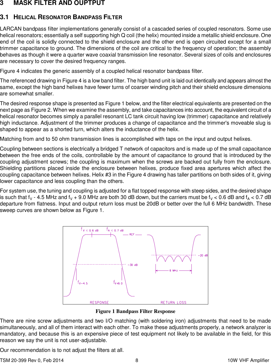
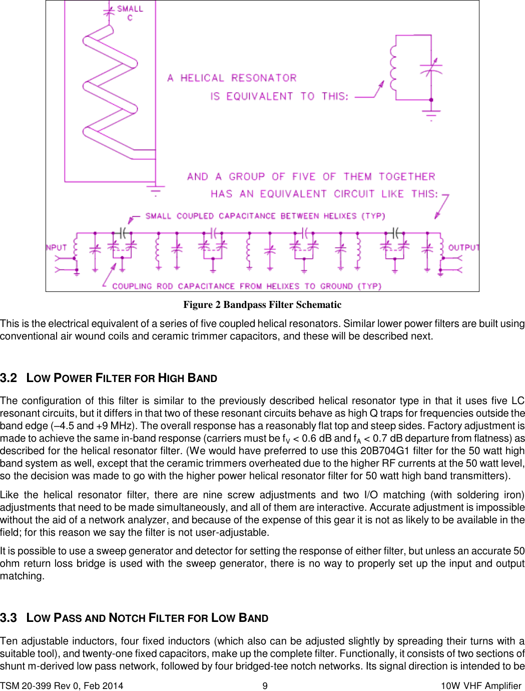
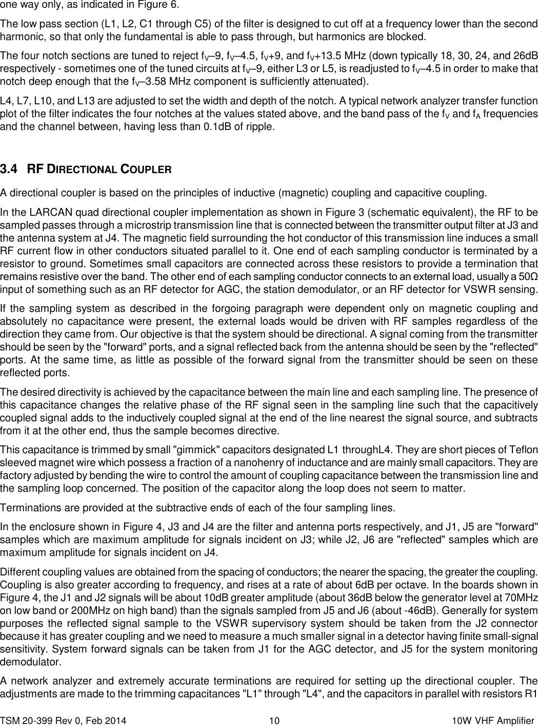
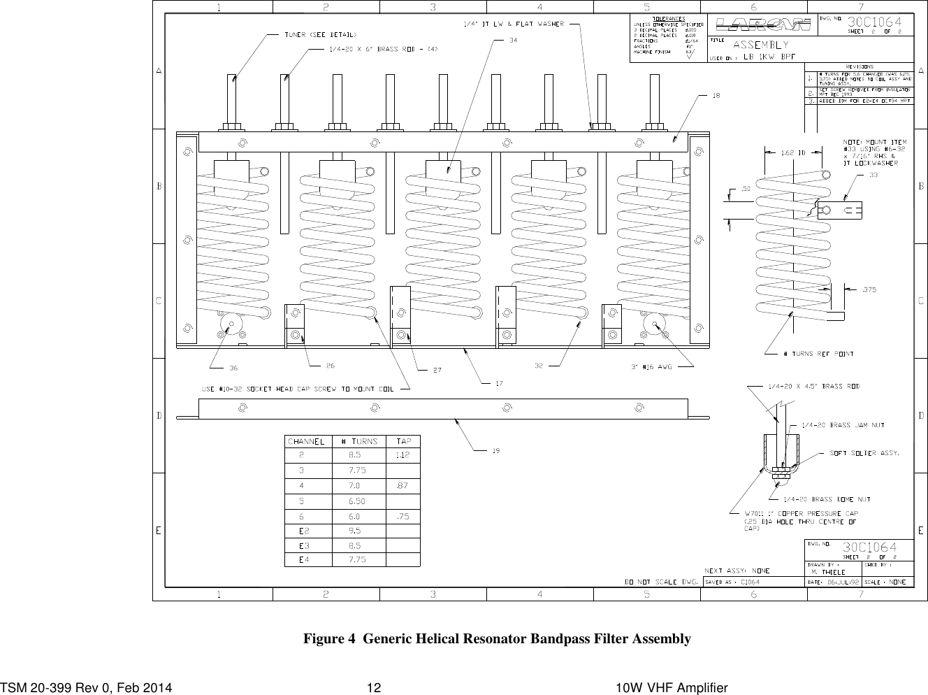
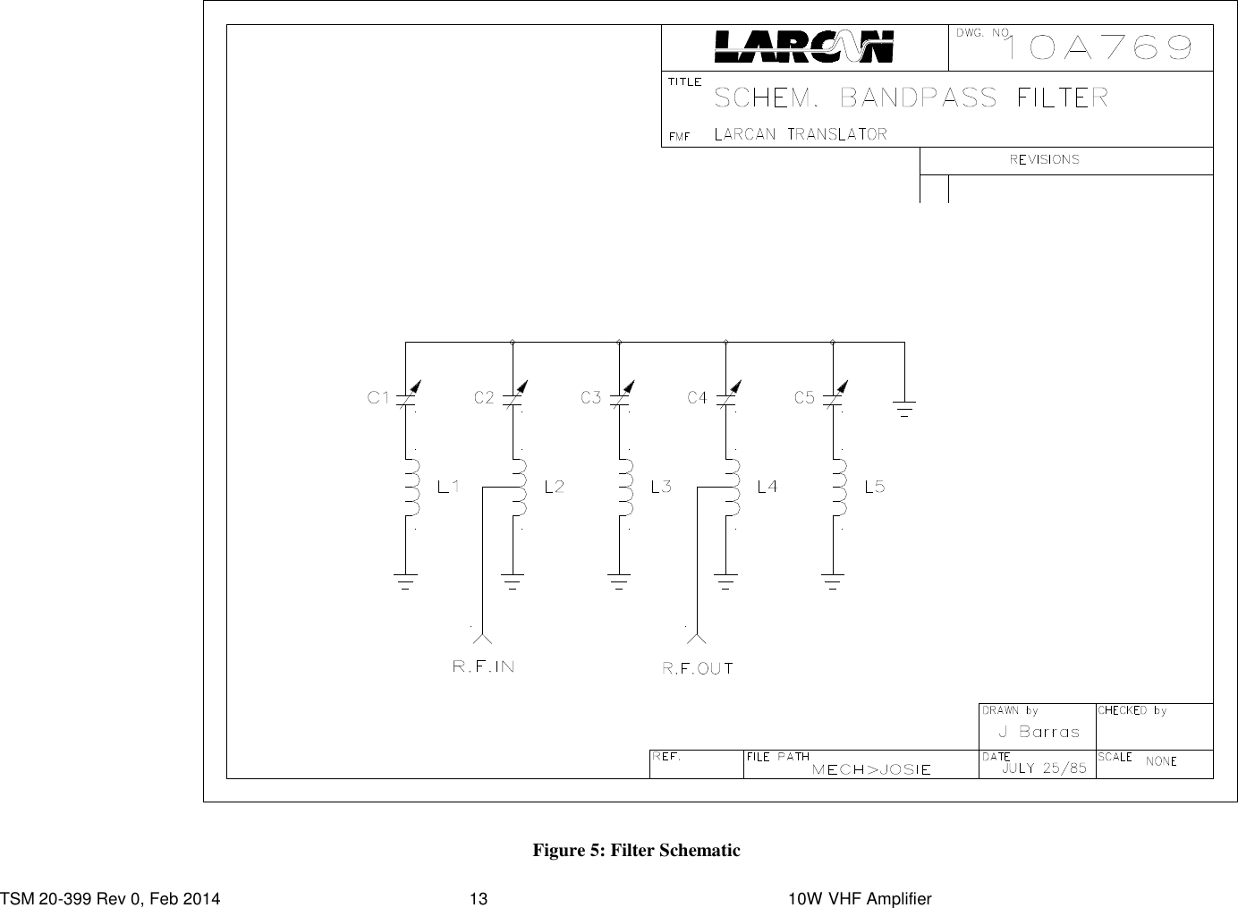
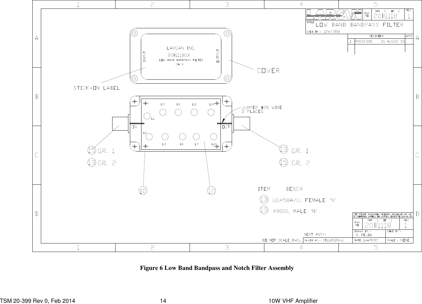
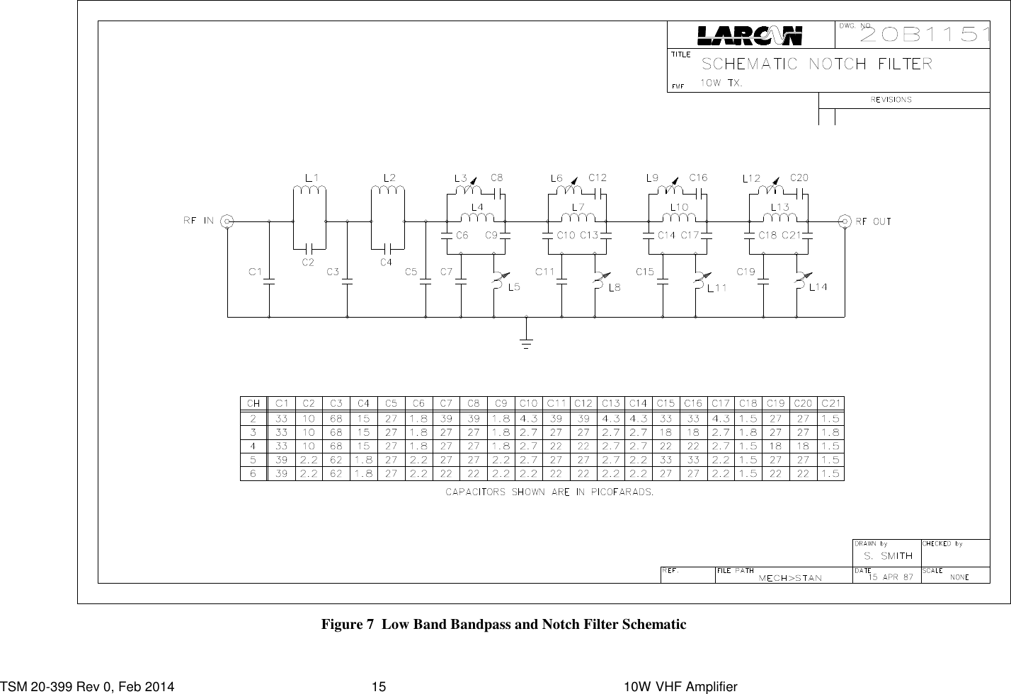
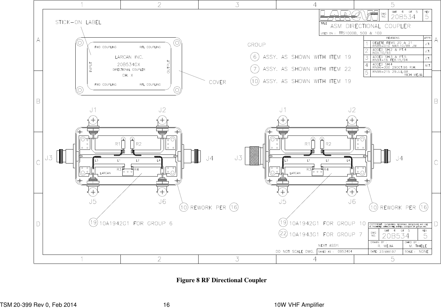
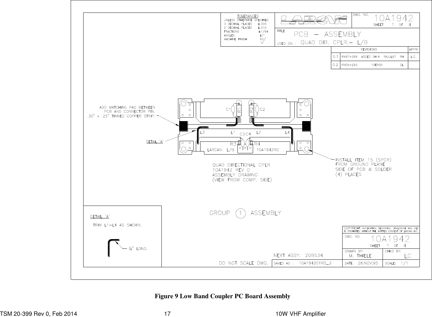
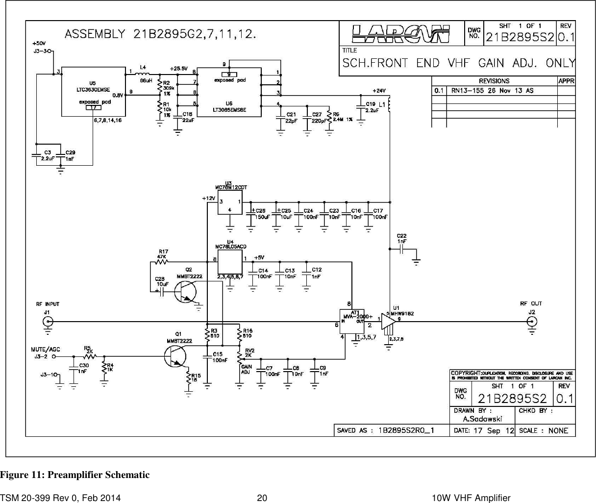
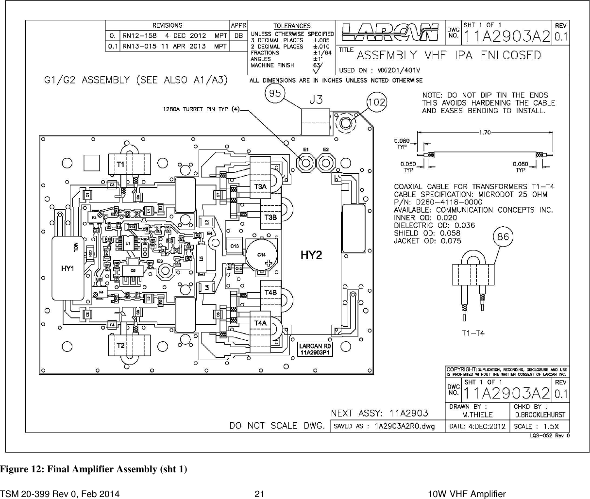
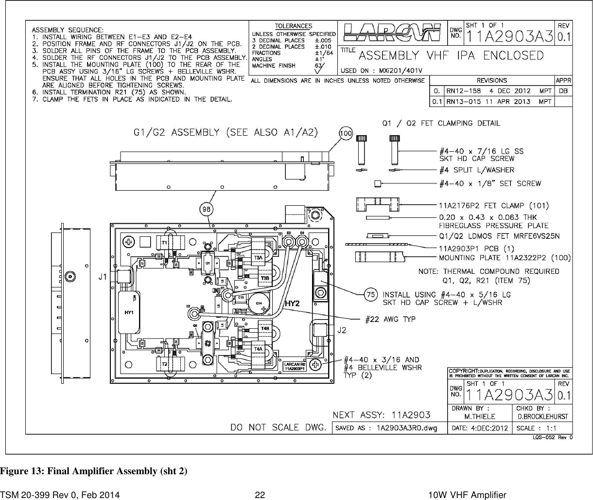
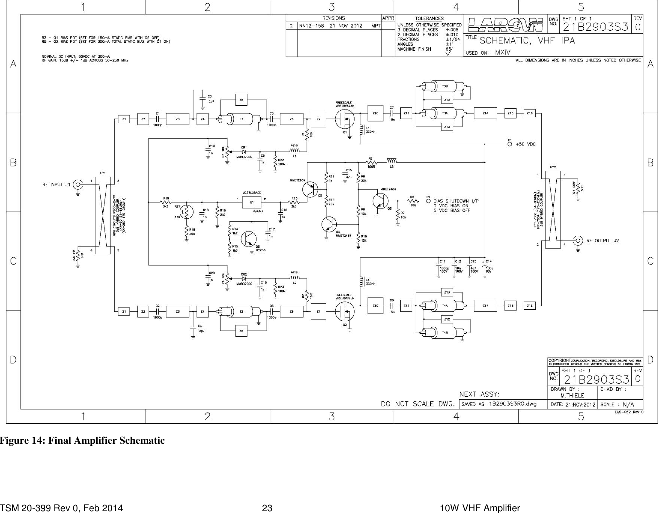
service manual
service manual
Navigation menu
Upload a User Manual
Namespaces
Wiki Guide
HTML
PDF
Info
Views
User Manual
Discussion / Help
Navigation