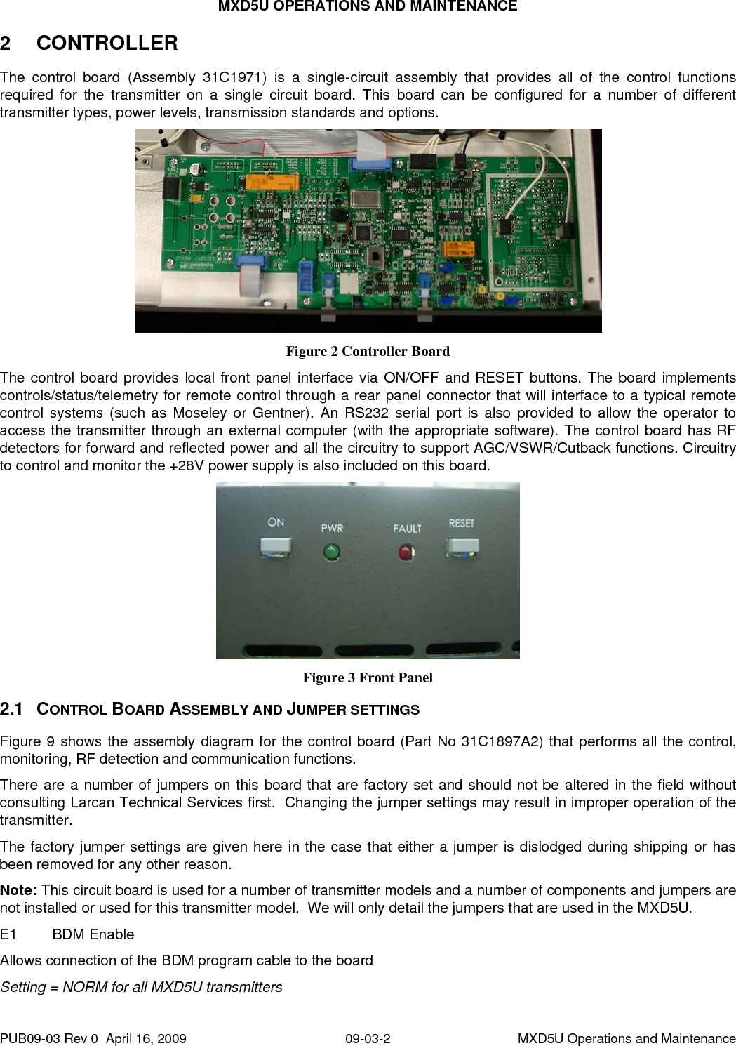
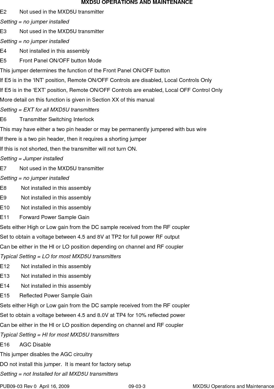
Larcan MXD5U Digital Television Broadcast Translator User Manual Heading 3
Larcan Inc Digital Television Broadcast Translator Heading 3
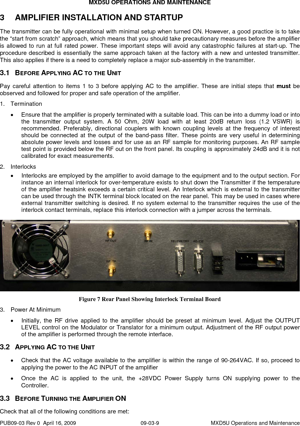
UserManual.wiki
>
Larcan
>
MXD5U User Manual
Users Manual
Navigation menu
Upload a User Manual
Namespaces
Wiki Guide
HTML
PDF
Info
Views
User Manual
Discussion / Help
Navigation

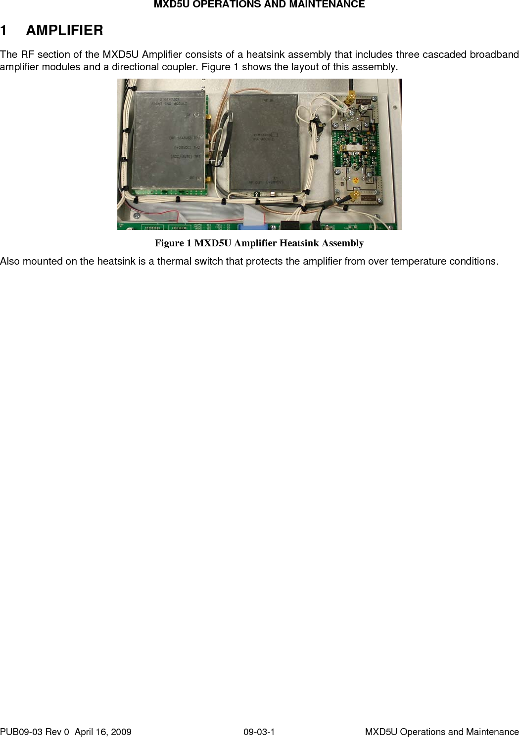
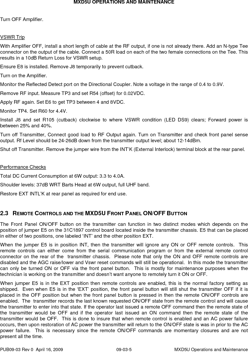
![MXD5U OPERATIONS AND MAINTENANCE 2.4.3 Remote Status Outputs There are only two remote statuses available to the operator, these being transmitter ON and an Error status. In the table of remote signals, all remote status have a RS_ prefix. The transmitter ON status is a relay contact that with one side of the contact connected to ground. When the transmitter is in the ON state, this relay closes providing a path to ground to the RS_TXON signal. Thus when this status sinks current to ground, it indicates that the transmitter is ON. The transmitter Error status is also an active low current sink to ground, but is implemented with the output transistor of an opto-isolator as shown in the diagram below. When the transistor sinks current to ground, it indicates that there is some fault condition with the transmitter. This fault is an indication to the operator that there is some problem with the transmitter (such as a VSWR trip, Interlock open or Power supply problem) that needs some attention. A ground reference pin is provided at pin 12 to ease the interface task since all these remote commands are active low and require a short to ground. The Error status is a current sinking open collector output that comes directly from the NPN transistor outputs of the opto-isolator devices. The available output sink current is dependent on the opto-isolator transfer ratio. Generally, one can expect at least 20mA of sinking current for each output listed here. Because these are open collector, they can be connected to maximum 30 VDC output. The active (true) condition whether high or low will depend on the specific status output. Figure 6 Remote Status Outputs 2.4.4 External1 Interlock There is a pair of terminals on the D-connector that is used for an external interlock to interface to any site alarms or shutdown conditions. These pins would expect a dry contact that is closed when there is no error condition. This External #1 interlock is in parallel with the two pin terminal block on the rear of the transmitter chassis. The transmitter applied its own +12V to one side of this interlock (the Ext1+ line) and will sense this +12V on the other interlock side (the Ext1- line). REMOTE SIGNAL PIN# DESCRIPTION RC_TXON 1 Control, Transmitter ON RC_VSWRRst 2 Control, VSWR Reset RS_TXON 3 Status, Transmitter ON Spare [Unused] 4 RT_FwdPwr 5 Telemetry, Forward Power Spare [Unused] 6 RT_CutBack 7 Telemetry, Cutback Voltage (1/2 Scale) Ext1- 8 External Interlock, Normally Open RC_TXOFF 9 Control, Transmitter OFF Spare [Unused] 10 PUB09-03 Rev 0 April 16, 2009 09-03-7 MXD5U Operations and Maintenance](https://usermanual.wiki/Larcan/MXD5U/User-Guide-1231306-Page-10.png)