Larcan MXD5U Digital Television Broadcast Translator User Manual Heading 3
Larcan Inc Digital Television Broadcast Translator Heading 3
Larcan >
Users Manual

MXD5U AMPLIFIER
TECHNICAL SERVICE MANUAL
LARCAN INC.
228 AMBASSADOR DRIVE
MISSISSAUGA, ONTARIO
CANADA L5T 2J2
PHONE: (905) 564-9222
FAX: (905) 564-9244
EMAIL: techservices@larcan.com
PUB09-03 Rev 0
16 April, 2009
MXD5U OPERATIONS AND MAINTENANCE
CONTENTS
1 AMPLIFIER ......................................................................................................................................................................1
2 CONTROLLER.................................................................................................................................................................2
2.1 CONTROL BOARD ASSEMBLY AND JUMPER SETTINGS ..................................................................................................2
2.2 REMOTE CONTROLS AND THE MXD5U FRONT PANEL ON/OFF BUTTON....................................................................4
2.3 EXTERNAL REMOTE CONTROL CONNECTIONS..............................................................................................................6
2.3.1 Remote Command Inputs.....................................................................................................................................6
2.3.2 Remote Telemetry Outputs...................................................................................................................................6
2.3.3 Remote Status Outputs.........................................................................................................................................7
2.3.4 External1 Interlock ..............................................................................................................................................7
2.4 EXTERNAL TRANSMITTER INTERLOCK .........................................................................................................................8
3 AMPLIFIER INSTALLATION AND STARTUP..........................................................................................................9
3.1 BEFORE APPLYING AC TO THE UNIT ............................................................................................................................9
3.2 APPLYING AC TO THE UNIT..........................................................................................................................................9
3.3 BEFORE TURNING THE AMPLIFIER ON .........................................................................................................................9
3.4 AMPLIFIER ON SEQUENCE..........................................................................................................................................10
3.4.1 Turning ON the Amplifier .................................................................................................................................10
4 TEST AND TROUBLESHOOTING .............................................................................................................................11
4.1 BENCH TEST PROCEDURES .........................................................................................................................................11
4.1.1 Front-End Module Bench Test Procedure .........................................................................................................11
4.1.2 IPA1 Bench Test Procedure...............................................................................................................................11
4.1.3 Pallet 21B1751 Bench Test Procedure ..............................................................................................................11
4.2 BASIC TROUBLESHOOTING TECHNIQUES ....................................................................................................................12
4.2.1 Amplifier Completely OFF.................................................................................................................................12
4.2.2 No RF Output.....................................................................................................................................................12
4.2.3 Output Reduced to 25% .....................................................................................................................................12
5 MAINTENANCE.............................................................................................................................................................13
5.1 DAILY.........................................................................................................................................................................13
5.2 MONTHLY...................................................................................................................................................................13
5.3 SEMI-ANNUALLY AND ANNUALLY .............................................................................................................................13
5.4 TRANSMITTER COOLING SYSTEM ...............................................................................................................................13
6 TEST EQUIPMENT SETUP..........................................................................................................................................14
7 SPECIFICATIONS .........................................................................................................................................................15
7.1 ELECTRICAL ...............................................................................................................................................................15
7.2 ENVIRONMENTAL .......................................................................................................................................................15
7.3 COOLING ....................................................................................................................................................................15
7.4 DIMENSIONS ...............................................................................................................................................................15
7.5 SHIPPING WEIGHT ......................................................................................................................................................15
FIGURES
FIGURE 1 MXD5U AMPLIFIER HEATSINK ASSEMBLY..................................................................................................................1
FIGURE 2 CONTROLLER BOARD....................................................................................................................................................2
FIGURE 3 FRONT PANEL ...............................................................................................................................................................2
FIGURE 4 REMOTE COMMAND INPUTS..........................................................................................................................................6
FIGURE 5 REMOTE TELEMETRY OUTPUTS ....................................................................................................................................6
FIGURE 6 REMOTE STATUS OUTPUTS ...........................................................................................................................................7
FIGURE 7 REAR PANEL SHOWING INTERLOCK TERMINAL BOARD................................................................................................9
PUB09-03 Rev 0 April 16, 2009 09-03-i MXi005U Operations and Maintenance
MXD5U OPERATIONS AND MAINTENANCE
FIGURE 8 TEST EQUIPMENT SETUP .............................................................................................................................................14
FIGURE 9 - FRONT END AMPLIFIER, MXD5U.............................................................................................................................16
FIGURE 10 - IPA ASSEMBLY, MXD5U.......................................................................................................................................17
FIGURE 11 - AMPLIFIER PALLET, MXD5U .................................................................................................................................18
FIGURE 12 MXD5U CONTROL BOARD ASSEMBLY ....................................................................................................................19
PUB09-03 Rev 0 April 16, 2009 09-03-ii MXi005U Operations and Maintenance
MXD5U OPERATIONS AND MAINTENANCE
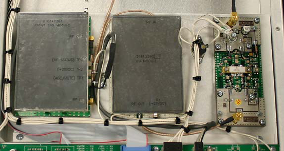
1 AMPLIFIER
The RF section of the MXD5U Amplifier consists of a heatsink assembly that includes three cascaded broadband
amplifier modules and a directional coupler. Figure 1 shows the layout of this assembly.
Figure 1 MXD5U Amplifier Heatsink Assembly
Also mounted on the heatsink is a thermal switch that protects the amplifier from over temperature conditions.
PUB09-03 Rev 0 April 16, 2009 09-03-1 MXD5U Operations and Maintenance
MXD5U OPERATIONS AND MAINTENANCE
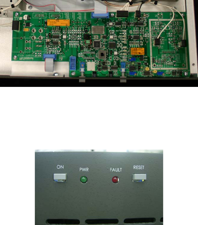
2 CONTROLLER
The control board (Assembly 31C1971) is a single-circuit assembly that provides all of the control functions
required for the transmitter on a single circuit board. This board can be configured for a number of different
transmitter types, power levels, transmission standards and options.
Figure 2 Controller Board
The control board provides local front panel interface via ON/OFF and RESET buttons. The board implements
controls/status/telemetry for remote control through a rear panel connector that will interface to a typical remote
control systems (such as Moseley or Gentner). An RS232 serial port is also provided to allow the operator to
access the transmitter through an external computer (with the appropriate software). The control board has RF
detectors for forward and reflected power and all the circuitry to support AGC/VSWR/Cutback functions. Circuitry
to control and monitor the +28V power supply is also included on this board.
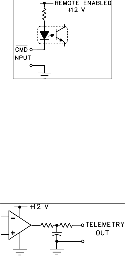
Figure 3 Front Panel
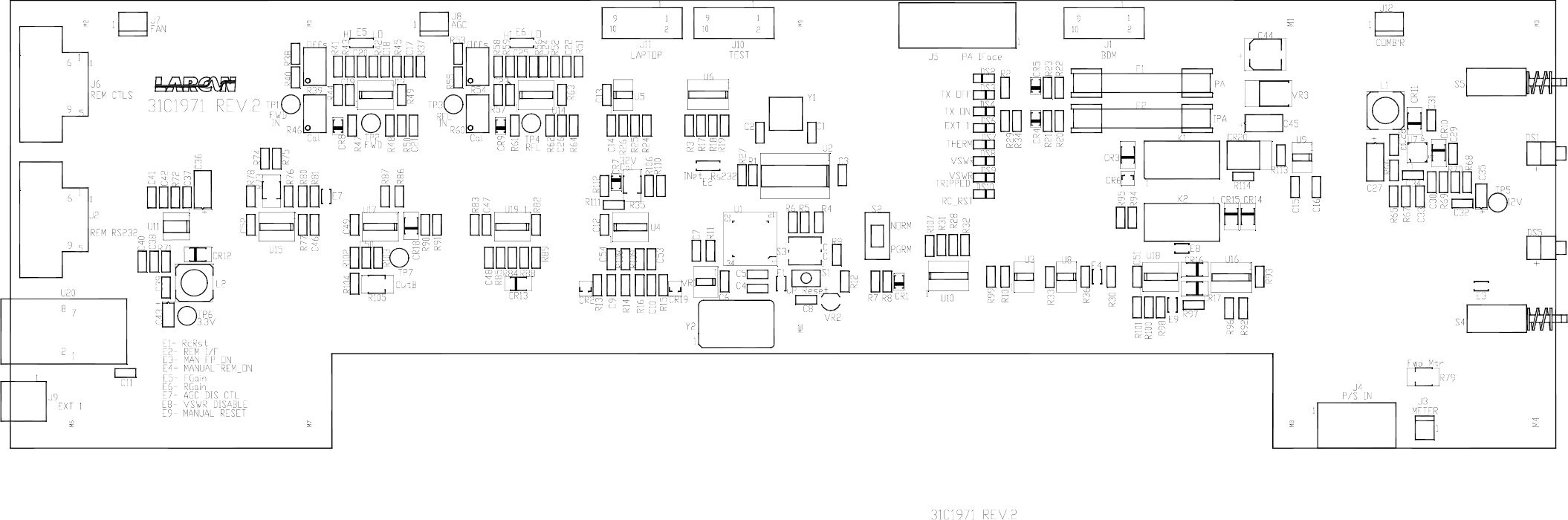
2.1 CONTROL BOARD ASSEMBLY AND JUMPER SETTINGS
Figure 9 shows the assembly diagram for the control board (Part No 31C1897A2) that performs all the control,
monitoring, RF detection and communication functions.
There are a number of jumpers on this board that are factory set and should not be altered in the field without
consulting Larcan Technical Services first. Changing the jumper settings may result in improper operation of the
transmitter.
The factory jumper settings are given here in the case that either a jumper is dislodged during shipping or has
been removed for any other reason.
Note: This circuit board is used for a number of transmitter models and a number of components and jumpers are
not installed or used for this transmitter model. We will only detail the jumpers that are used in the MXD5U.
E1 BDM Enable
Allows connection of the BDM program cable to the board
Setting = NORM for all MXD5U transmitters
PUB09-03 Rev 0 April 16, 2009 09-03-2 MXD5U Operations and Maintenance
MXD5U OPERATIONS AND MAINTENANCE
E2 Not used in the MXD5U transmitter
Setting = no jumper installed
E3 Not used in the MXD5U transmitter
Setting = no jumper installed
E4 Not installed in this assembly
E5 Front Panel ON/OFF button Mode
This jumper determines the function of the Front Panel ON/OFF button
If E5 is in the ‘INT’ position, Remote ON/OFF Controls are disabled, Local Controls Only
If E5 is in the ‘EXT’ position, Remote ON/OFF Controls are enabled, Local OFF Control Only
More detail on this function is given in Section XX of this manual
Setting = EXT for all MXD5U transmitters
E6 Transmitter Switching Interlock
This may have either a two pin header or may be permanently jumpered with bus wire
If there is a two pin header, then it requires a shorting jumper
If this is not shorted, then the transmitter will not turn ON.
Setting = Jumper installed
E7 Not used in the MXD5U transmitter
Setting = no jumper installed
E8 Not installed in this assembly
E9 Not installed in this assembly
E10 Not installed in this assembly
E11 Forward Power Sample Gain
Sets either High or Low gain from the DC sample received from the RF coupler
Set to obtain a voltage between 4.5 and 8V at TP2 for full power RF output
Can be either in the HI or LO position depending on channel and RF coupler
Typical Setting = LO for most MXD5U transmitters
E12 Not installed in this assembly
E13 Not installed in this assembly
E14 Not installed in this assembly
E15 Reflected Power Sample Gain
Sets either High or Low gain from the DC sample received from the RF coupler
Set to obtain a voltage between 4.5 and 8.0V at TP4 for 10% reflected power
Can be either in the HI or LO position depending on channel and RF coupler
Typical Setting = HI for most MXD5U transmitters
E16 AGC Disable
This jumper disables the AGC circuitry
DO not install this jumper. It is meant for factory setup
Setting = not Installed for all MXD5U transmitters
PUB09-03 Rev 0 April 16, 2009 09-03-3 MXD5U Operations and Maintenance

MXD5U OPERATIONS AND MAINTENANCE
E18 Direct Vswr Relay reset from the Remote Reset Command
This jumper allows the Remote Reset Command to directly clear the VSWR trip relay
Setting = Installed for all MXD5U transmitters
E19 Forward Power Detection Type
Setting = PK for all MXD5U transmitters
2.2 POWER CALIBRATION, AGC AND CUTBACK SETUP
HIGH VOLTAGE
RISK OF EXPOSURE TO VOLTAGES UP TO 260VAC
Use particular caution near the power supply’s transformer terminals.
The following setup is for the overall assembly of the MXD5U transmitter. It assumes that all individual
components in the assembly have been tested and biased, including the Control Board, the Amplifier Boards and
the Directional Coupler.
Note that the tests below are factory specific and therefore do not include the use of an Output Mask Filter. If one
is available, it can be inserted and setup performed as described in the procedure, with the following exceptions.
- perform power calibration at the filter output calibrating to a 5W level
- installation and alterations of test loads are done at the filter output, not transmitter RF Output.
PLEASE NOTE SAFETY WARNING ABOVE.
Connect a jumper wire across the terminals of the INT’K (External Interlock) terminal block at the rear panel. This
is temporary and must be removed when tests are completed.
Confirm Amplifier Bias
Terminate RF Out with 50R (min 20W rating). Apply no rf drive.
Turn ON Amplifier at front panel. Check for 28VDC at Amplifiers.
Check Amplifier Bias Currents: Front End Amplifier: 0.2-0.3A, IPA:1A, Amplifier Pallet: 1.0A
Power Calibration
Set R105 completely CCW. Ensure J8 is connected.
Remove all Control board jumpers except;
- E7 and E8 IN
- E2 to RS232
Monitor TP1. Adjust R39 for 0.02VDC.
Apply signal to get full power + filter losses at output. Approx 6W.
Check out-of-band shoulder levels at 6W for the broadcast channel before proceeding.
Set E5 to get 4-8V at TP1. Monitor TP2; adjust R46 for 4.00V.
Adjust R79 for 100% meter reading.
Increase Power to get 110%. Remove E7 and set R73 to get 4.0V on TP3. Meter should again read 100%.
PUB09-03 Rev 0 April 16, 2009 09-03-4 MXD5U Operations and Maintenance

MXD5U OPERATIONS AND MAINTENANCE
Turn OFF Amplifier.
VSWR Trip
With Amplifier OFF, install a short length of cable at the RF output, if one is not already there. Add an N-type Tee
connector on the output of the cable. Connect a 50R load on each of the two female connections on the Tee. This
results in a 10dB Return Loss for VSWR setup.
Ensure E8 is installed. Remove J8 temporarily to prevent cutback.
Turn on the Amplifier.
Monitor the Reflected Detect port on the Directional Coupler. Note a voltage in the range of 0.4 to 0.9V.
Remove RF input. Measure TP3 and set R54 (offset) for 0.02VDC.
Apply RF again. Set E6 to get TP3 between 4 and 8VDC.
Monitor TP4. Set R60 for 4.4V.
Install J8 and set R105 (cutback) clockwise to where VSWR condition (LED DS9) clears; Forward power is
between 25% and 40%.
Turn off Transmitter, Connect good load to RF Output again. Turn on Transmitter and check front panel sense
output. Rf Level should be 24-26dB down from the transmitter output level; about 12-14dBm.
Shut off Transmitter. Remove the jumper wire from the INT’K (External Interlock) terminal block at the rear panel.
Performance Checks
Total DC Current Consumption at 6W output: 3.3 to 4.0A.
Shoulder levels: 37dB WRT Barts Head at 6W output, full UHF band.
Restore EXT INTL’K at rear panel as required for end use.
2.3 REMOTE CONTROLS AND THE MXD5U FRONT PANEL ON/OFF BUTTON
The Front Panel ON/OFF button on the transmitter can function in two distinct modes which depends on the
position of jumper E5 on the 31C1897 control board located inside the transmitter chassis. E5 that can be placed
in either of two positions, one labeled ‘INT’ and the other position EXT.
When the jumper E5 is in position INT, then the transmitter will ignore any ON or OFF remote controls. This
remote controls can either come from the serial communication program or from the external remote control
connector on the rear of the transmitter chassis. Please note that only the ON and OFF remote controls are
disabled and the AGC raise/lower and Vswr reset commands will still be operational. In this mode the transmitter
can only be turned ON or OFF via the front panel button. This is mostly for maintenance purposes when the
technician is working on the transmitter and doesn’t want anyone to remotely turn it ON or OFF.
When jumper E5 is in the EXT position then remote controls are enabled, this is the normal factory setting as
shipped. Even when E5 is in the ‘EXT’ position, the front panel button will still shut the transmitter OFF if it is
placed in the OFF position but when the front panel button is pressed in then the remote ON/OFF controls are
enabled. The transmitter records the last known requested ON/OFF state from the remote control and will cause
the transmitter to enter into that state. If the operator last issued a remote OFF command then the remote state of
the transmitter would be OFF and if the operator last issued an ON command then the remote state of the
transmitter would be OFF. This is done to insure that when remote control is enabled and an AC power failure
occurs, then upon restoration of AC power the transmitter will return to the ON/OFF state is was in prior to the AC
power failure. This is necessary since the remote ON/OFF commands are momentary closures and are not
present all the time.
PUB09-03 Rev 0 April 16, 2009 09-03-5 MXD5U Operations and Maintenance
MXD5U OPERATIONS AND MAINTENANCE
2.4
2.4.1
EXTERNAL REMOTE CONTROL CONNECTIONS
External remote controls are intended to interfacing to a third party remote control vendor such as Moseley or
Gentner if such systems are installed or available at the transmitter site. These external controls function in
parallel with the serial remote commands implemented with the Larcan supplied remote control program.
These remote signals are available on the 15-pin D-connector labeled Telemetry on the rear panel of the MXD5U
transmitter. The remote controls can be broken down into four categories, control inputs, status outputs,
telemetry outputs and interlock as follows:
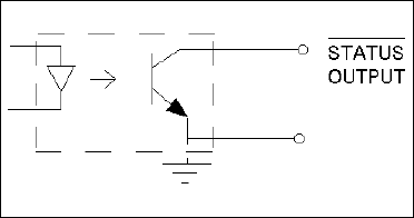
Remote Command Inputs
There are only three remote commands available to the operator, these being TX ON, TX OFF and VSWR Reset.
In the table of remote signals, all remote commands have an RC_prefix.
All remote controls are active low, opto-isolated inputs configured as shown at left, all of which require a GROUND
for assertion and the activator to be able to sink 15mA or more for at least 200ms to accomplish reliable keying.
Each of these is current-limited by an individual resistor. A ground reference pin is provided at pin 12 to ease the
interface task since all these remote commands are active low and require a short to ground.
Figure 4 Remote Command Inputs
2.4.2 Remote Telemetry Outputs
There are only four remote telemetries available to the operator, these being RF forward power, RF reflected power,
AGC voltage and Cutback voltage. In the table of remote signals, all remote commands have a RT_ prefix.
The only further note on the telemetry outputs concern the AGC and Cutback telemetry levels. These levels are
normally sent to the PreAmp attenuator and range from 0V to about 10V. The circuit that generates these
telemetries for the remote interface only has a range of 0V to 5V and so the values of these two telemetries are
actually half of their true value. That is an AGC telemetry reading of 2.3V actually represents an AGC voltage
level to the PreAmp attenuator of 4.6V.
All telemetry outputs of the transmitter are designed to operate between zero and +5V, referenced to ground.
Where possible and practical, factory calibration is standardised on 100% normal power or 100% normal voltage as
applicable, and adjusted to deliver +4V to the appropriate telemetry output. All come from op-amps that can supply
only a few mA. A ground reference pin is provided at pin 12 to ease the interface task since all these remote
commands are active low and require a short to ground.
Figure 5 Remote Telemetry Outputs
PUB09-03 Rev 0 April 16, 2009 09-03-6 MXD5U Operations and Maintenance
MXD5U OPERATIONS AND MAINTENANCE
2.4.3 Remote Status Outputs
There are only two remote statuses available to the operator, these being transmitter ON and an Error status. In the
table of remote signals, all remote status have a RS_ prefix.
The transmitter ON status is a relay contact that with one side of the contact connected to ground. When the
transmitter is in the ON state, this relay closes providing a path to ground to the RS_TXON signal. Thus when this
status sinks current to ground, it indicates that the transmitter is ON.
The transmitter Error status is also an active low current sink to ground, but is implemented with the output transistor
of an opto-isolator as shown in the diagram below. When the transistor sinks current to ground, it indicates that there
is some fault condition with the transmitter. This fault is an indication to the operator that there is some problem with
the transmitter (such as a VSWR trip, Interlock open or Power supply problem) that needs some attention. A ground
reference pin is provided at pin 12 to ease the interface task since all these remote commands are active low and
require a short to ground.
The Error status is a current sinking open collector output that comes directly from the NPN transistor outputs of the
opto-isolator devices. The available output sink current is dependent on the opto-isolator transfer ratio. Generally,
one can expect at least 20mA of sinking current for each output listed here. Because these are open collector, they
can be connected to maximum 30 VDC output. The active (true) condition whether high or low will depend on the
specific status output.
Figure 6 Remote Status Outputs
2.4.4 External1 Interlock
There is a pair of terminals on the D-connector that is used for an external interlock to interface to any site alarms or
shutdown conditions. These pins would expect a dry contact that is closed when there is no error condition. This
External #1 interlock is in parallel with the two pin terminal block on the rear of the transmitter chassis. The
transmitter applied its own +12V to one side of this interlock (the Ext1+ line) and will sense this +12V on the other
interlock side (the Ext1- line).
REMOTE SIGNAL PIN# DESCRIPTION
RC_TXON 1 Control, Transmitter ON
RC_VSWRRst 2 Control, VSWR Reset
RS_TXON 3 Status, Transmitter ON
Spare [Unused] 4
RT_FwdPwr 5 Telemetry, Forward Power
Spare [Unused] 6
RT_CutBack 7 Telemetry, Cutback Voltage (1/2 Scale)
Ext1- 8 External Interlock, Normally Open
RC_TXOFF 9 Control, Transmitter OFF
Spare [Unused] 10
PUB09-03 Rev 0 April 16, 2009 09-03-7 MXD5U Operations and Maintenance
MXD5U OPERATIONS AND MAINTENANCE
RS_TXErr 11 Status, Transmitter Error
Ground Reference 12 Ground Reference
RT_RflPwr 13 Telemetry, Reflected Power
RT_AGC 14 Telemetry, AGC Voltage (1/2 Scale)
Ext1+ 15 External Interlock, (+12V Armed)
2.5 EXTERNAL TRANSMITTER INTERLOCK
The transmitter provides the customer a set of contacts where an external interlock can be applied to control the
ON state of the transmitter. The purpose of this interlock is to shut down the transmitter if there is sensed an
emergency condition (such as a building fire or smoke alarm) or it there is some RF output switch that is going to
be moved and the RF output of the transmitter needs to be shut off temporarily when the switch is in transit. If
there is no application for this interlock then the customer must insure that it is shorted out (i.e., closed) so that
the transmitter is enabled to be turned ON.
The external1 interlock contacts are available in two separate locations. The first location is on the two pin terminal
block on the rear of the transmitter chassis. This is the more likely and convenient place for the External1 interlock
to be connected. A second parallel set of contacts is located on the 15-pin Telemetry D-connector on the rear of the
transmitter chassis. Only one set of these contacts need to be closed to enable the transmitter since they are in
parallel.
These pins would expect a dry contact that is closed when there is no error condition. This External #1 interlock is in
parallel with the two pin terminal block on the rear of the transmitter chassis. The transmitter applied its own +12V to
one side of this interlock (the Ext1+ line) and will sense this +12V on the other interlock side (the Ext1- line).
PUB09-03 Rev 0 April 16, 2009 09-03-8 MXD5U Operations and Maintenance

MXD5U OPERATIONS AND MAINTENANCE
3
3.1
AMPLIFIER INSTALLATION AND STARTUP
The transmitter can be fully operational with minimal setup when turned ON. However, a good practice is to take
the “start from scratch” approach, which means that you should take precautionary measures before the amplifier
is allowed to run at full rated power. These important steps will avoid any catastrophic failures at start-up. The
procedure described is essentially the same approach taken at the factory with a new and untested transmitter.
This also applies if there is a need to completely replace a major sub-assembly in the transmitter.
BEFORE APPLYING AC TO THE UNIT
Pay careful attention to items 1 to 3 before applying AC to the amplifier. These are initial steps that must be
observed and followed for proper and safe operation of the amplifier.
1. Termination
• Ensure that the amplifier is properly terminated with a suitable load. This can be into a dummy load or into
the transmitter output system. A 50 Ohm, 20W load with at least 20dB return loss (1.2 VSWR) is
recommended. Preferably, directional couplers with known coupling levels at the frequency of interest
should be connected at the output of the band-pass filter. These points are very useful in determining
absolute power levels and losses and for use as an RF sample for monitoring purposes. An RF sample
test point is provided below the RF out on the front panel. Its coupling is approximately 24dB and it is not
calibrated for exact measurements.
2. Interlocks
• Interlocks are employed by the amplifier to avoid damage to the equipment and to the output section. For
instance an internal interlock for over-temperature exists to shut down the Transmitter if the temperature
of the amplifier heatsink exceeds a certain critical level. An Interlock which is external to the transmitter
can be used through the INTK terminal block located on the rear panel. This may be used in cases where
external transmitter switching is desired. If no system external to the transmitter requires the use of the
interlock contact terminals, replace this interlock connection with a jumper across the terminals.
Figure 7 Rear Panel Showing Interlock Terminal Board
3. Power At Minimum
• Initially, the RF drive applied to the amplifier should be preset at minimum level. Adjust the OUTPUT
LEVEL control on the Modulator or Translator for a minimum output. Adjustment of the RF output power
of the amplifier is performed through the remote interface.
3.2
3.3
APPLYING AC TO THE UNIT
• Check that the AC voltage available to the amplifier is within the range of 90-264VAC. If so, proceed to
applying the power to the AC INPUT of the amplifier
• Once the AC is applied to the unit, the +28VDC Power Supply turns ON supplying power to the
Controller.
BEFORE TURNING THE AMPLIFIER ON
Check that all of the following conditions are met:
PUB09-03 Rev 0 April 16, 2009 09-03-9 MXD5U Operations and Maintenance
MXD5U OPERATIONS AND MAINTENANCE
1. Modulator is Ready.
• Usually in the application of AC, the Modulator goes through its warm-up sequence. Ensure that it has
done so.
2. CONTROLLER is ready.
• If there were prior faults (see front panel LED), clear them by pushing the RESET button.
3. INTERLOCKS are closed or OK.
• Interlocks and Status are OK.
4. The TX is OFF.
• Push the Front Panel ON/OFF button so that it is NOT pushed in.
3.4
3.4.1
AMPLIFIER ON SEQUENCE
Upon depressing the ON button the +28V power supply is switched on at the amplifier boards.
Turning ON the Amplifier
5. Push the front panel ON button. The Amplifier should now be ON, producing RF at the output.
6. The cooling fan turns on.
7. Monitor the +28V power supply voltage and current on the LCD screen. With the user interface program the
power supply can be checked by observing the voltage and power supply status indicator. The voltage
reading should be about 28V and the power supply status indicator should be green.
ALLOW THE AMPLIFIER SOME WARM-UP TIME!
Only after the transmitter has been ON for approximately 15 minutes should you perform fine adjustments.
The amplifier must be allowed to reach its operating temperature for stable and consistent operation. The
Power Amplifier in the transmitter is equipped with thermal compensation circuits, which reduce the output
power when the temperature rises. Therefore, the operating temperature must be reached before adjusting
the RF level to its proper level. The amplifier is also equipped with Automatic Gain Control, primarily designed
to prevent the transmitter from overpower or overdrive condition.
8. Increase the RF output by slowly adjusting the Modulator or Translator output level control. Increase the
power to 100%. At this time the proper warm-up period begins.
9. With the amplifier fully functional and adjusted to its final setting, record keeping becomes very important.
Record the current, voltage, power, etc. This data can be used as a very valuable troubleshooting tool later.
Below is typical test data pertaining to the amplifier at 100% output power.
TYPICAL DATA read on the User Interface Program
FWD 100%
RFL 00.1%
AGC 1.0V
CUTB 0.1V
PS VOLTS 28.0V
PUB09-03 Rev 0 April 16, 2009 09-03-10 MXD5U Operations and Maintenance

MXD5U OPERATIONS AND MAINTENANCE
4
4.1
4.1.1
4.1.2
4.1.3
TEST AND TROUBLESHOOTING
BENCH TEST PROCEDURES
The following procedures are test instructions for the amplifier modules comprising the complete amplifier
assembly.
Front-End Amplifier (Figure 9) Bench Test Procedure
• Connect a +28V (1A current limit) power supply to TP2.
• Apply a 0dBm (1mW) RF input to the amplifier.
• Turn RV2 fully clockwise. The front-end should have a gain of 13dB. Adjusting RV2 from one extreme to
the other should vary the gain by a minimum of 20dB. Set RV2 fully clockwise.
• RF Mute Check: Connect a variable supply to TP1. Gradually increase the voltage until the gain drops by
20dB or more. The applied voltage should be approximately 7 volts.
• Telemetry: Monitor TP3. Note voltage decrease to 0V DC when RF output has been muted.
IPA (Figure 10) Bench Test Procedure
This amplifier must be mounted on a properly sized heatsink for testing.
• Connect a suitable load to the output of the Pre Amplifier.
• On the unit under test, set RV200 fully clockwise and set RV110 fully counter-clockwise.
• Set variable power supply to 28.0V and set its current limit to 1 ampere.
• Apply the +28V to the feed through capacitor of the pre-amp shield box.
• Adjust RV3 to achieve 6.5 ±0.2V at the junction of R5 and RV100.
• Adjust RV200 to achieve total current draw of 300 ±20mA.
• Check that the junction of R100 and CR100 measures between 3.5 and 5.5 volts.
• Adjust RV110 to raise total current draw to 1.0A ±50mA.
• Check that the junction of R110 and CR110 measures between 3.5 and 5.5 volts.
• Increase the power supply current limiting to 2.2A.
• Increase RV3 clockwise slowly and check that the maximum current limits itself at 1.6 ±0.1 Amp but do
not allow current to go above 2A while performing this test.
• Reset RV3 to achieve 6.5 ±0.2V measured at the junction of R5 and RV100.
• Check balance of the two transistors with a voltmeter connected between the hot sides of C105 and
C115; the difference in voltage should be less than 3mV.
• Apply RF drive (max. +18dBm from a pre-amp) and adjust C101, C103, C111, and C113 for minimum
frequency response ripple and flat response. Gain should be a minimum of 17dB with maximum variation
less than 0.5dB over the frequency range 470 MHz through 860 MHz (Note: output will then be about
+33dBm or 2 Watts for an input of +16dBm, so make sure you properly protect your test equipment).
• If roll off at the higher frequencies prevents meeting this gain-bandwidth specification, it may be
necessary to replace either C103 or C113 or both with a higher value; use variable capacitor made by
Johanson, part # 16E2320-2, which is 2.5 to 10pF.
Amplifier Pallet (Figure 11) Bench Test Procedure
• BIAS SETTING: Connect a 50-Ohm load, having a minimum power rating of 10W, to the output of the pallet.
PUB09-03 Rev 0 April 16, 2009 09-03-11 MXD5U Operations and Maintenance

MXD5U OPERATIONS AND MAINTENANCE
• Before applying +28V to the module, adjust R12 fully clockwise. Limit the power supply current to 3.0A.
• Apply +28V to the B+ terminal. Monitor the current and adjust R12 counter clockwise (CCW) for a total
current of about 1.0A + 0.05A.
• Proceed to the next step if a network analyzer or similar equipment is available.
• RF SWEEP: Adjust C7 for best frequency response. With the bias set at 1.0A, the gain in the range of
470MHz to 860 MHz should be 15 to 16dB.
4.2
4.2.1
4.2.2
4.2.3
BASIC TROUBLESHOOTING TECHNIQUES
As mentioned earlier, one of the best tools in troubleshooting is knowing what the nominal figures or typical
values of the amplifier when it is at its normal performance. If a fault condition occurs, then you can compare the
data taken previously with the present conditions and come up with a reasonable conclusion about what is at
fault.
The following describes some fault conditions and possible solutions.
Amplifier Completely OFF
The amplifier is equipped with a fused AC line filter. Although it rarely happens, abnormal conditions such as
power surges may cause the fuse to blow. Blown AC fuses will completely shutdown the amplifier. In this case,
replacing the fuse will rectify the problem.
No RF Output
• Check for proper power supply voltage.
• Check for potential connector problems causing either no drive to a module pallet (input connector) or VSWR
(output connector) problems.
Output Reduced to 25%
If the output is approximately 25%, a possible cause is a failure of one of the devices in the IPA. This stage has
dual devices so that if one fails the output of that stage will be reduced to quarter power (25%). A measurement of
the current drawn by the amplifier will determine if this condition exists. The IPA usually draws 1.0A. If the current
is 0.5A, then this is the case.
PUB09-03 Rev 0 April 16, 2009 09-03-12 MXD5U Operations and Maintenance
MXD5U OPERATIONS AND MAINTENANCE
5 MAINTENANCE
5.1
5.2
5.3
5.4
Equipment which is regularly and carefully maintained is far less likely to be subject to sudden failure than that
which is operated without regard to basic maintenance requirements. A detailed preventive maintenance program
should be established to ensure that the original efficiency and picture quality is maintained throughout the life of
the equipment. Given reasonable care and attention, the transmitter will provide efficient and reliable service for
many years.
Preventive maintenance techniques do not necessarily involve extensive dismantling of the various assemblies;
on the contrary, this practice is to be discouraged unless a valid reason exists for doing so. Preventive
maintenance is more directed at detailed physical inspection and the general observation of the equipment during
and after operation, to detect the presence of any abnormality, which, if not corrected, might result in operational
failure.
In preparing any maintenance program, the frequency and scope of the inspections must be determined and to a
great degree will be influenced by site location and the station's market parameters and consequently its hours of
operation, equipment configuration, and technical personnel deployment. For example, is the station on the air for
24 hours-a-day? Are there main/standby transmitters and are they attended or unattended?
In general, the following routines should form the basis of any maintenance program.
DAILY
At an attended site, the operator is afforded the opportunity to make frequent checks on the equipment and
thereby increase his/her familiarity with its operation. The transmitter log entries made during these checks would
include all meter readings, also any irregularity in performance or in picture quality, for later analysis. An
unattended site where equipment is operated by remote control and monitored by telemetry and a high quality off-
air receiver or demodulator can also be continuously checked for performance by studio technical personnel.
MONTHLY
In addition to the normal operational tests, thorough physical inspection of every piece of equipment should be
made, with all power turned off. All surfaces should be dusted off or wiped down, terminal boards checked for
loose connections, and all components examined for any evidence of overheating. Air filter media should be
inspected and replaced if necessary. High-pressure air, not over 20psi, can be used with discretion to dislodge
dust from inaccessible places.
SEMI-ANNUALLY AND ANNUALLY
Check all external RF connections for tightness, looking specifically for any discoloration, which might indicate a
loose inner connector, flange or sleeve coupling. Test the passive RF system with a transmission test set or
network analyzer, if one is available, to identify any potential problems with the antenna or line. Inspect and clean
contacts on all switches and contactors; carefully redress contact surfaces if pitted.
Check the operation of all interlocks including patch panel, dummy load, air and thermal switches and emergency
interlocks (if applicable).
TRANSMITTER COOLING SYSTEM
All cooling fans in the transmitter are fitted with sealed bearings requiring no lubrication during the lifetime of the
motor.
PUB09-03 Rev 0 April 16, 2009 09-03-13 MXD5U Operations and Maintenance
MXD5U OPERATIONS AND MAINTENANCE
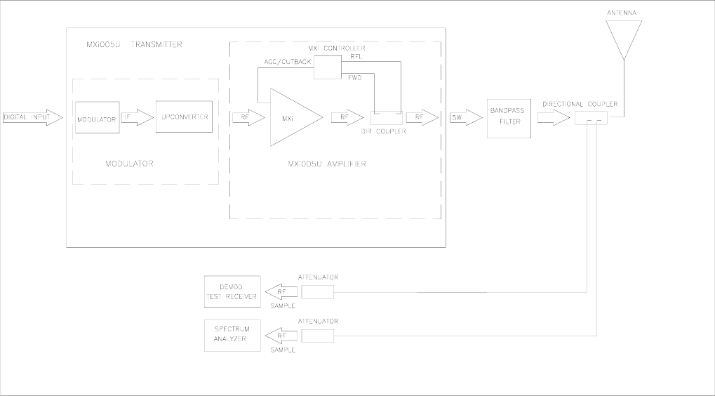
6 TEST EQUIPMENT SETUP
Figure 8 Test Equipment Setup
PUB09-03 Rev 0 April 16, 2009 09-03-14 MXD5U Operations and Maintenance
MXD5U OPERATIONS AND MAINTENANCE
7
7.1
7.2
7.3
7.4
7.5
SPECIFICATIONS
Specifications are subject to change without notice.
ELECTRICAL
AC Line Input .....................................................................................................................90 to 264VAC, 50 to 60Hz
Power Consumption, black picture + 10% aural ................................................................................. 220VA (typical)
ENVIRONMENTAL
Ambient Temperature .....................................................................................................0°C to +45°C (0°F to 113°F)
Humidity ............................................................................................................................................................... 95%
Altitude ..............................................................................................................................................................3500m
COOLING
1 muffin fan pulls air through the front panel and heatsink, and out through the rear panel.
DIMENSIONS
The Amplifier and Modulator chassis are standard 19" rack wide units.
Height
Amplifier..........................................................................................................................................3.5" (2RU)
Modulator......................................................................................................................................1.75” (1RU)
Total Height ..................................................................................................................................5.25” (3RU)
SHIPPING WEIGHT
Weight ……………………………….……… .....................................................................Approximately 6.5kg (14lbs)
PUB09-03 Rev 0 April 16, 2009 09-03-15 MXD5U Operations and Maintenance
MXD5U OPERATIONS AND MAINTENANCE
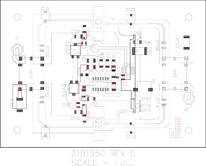
Figure 9 - Front End Amplifier, MXD5U
PUB09-03 Rev 0 April 16, 2009 09-03-16 MXD5U Operations and Maintenance
MXD5U OPERATIONS AND MAINTENANCE
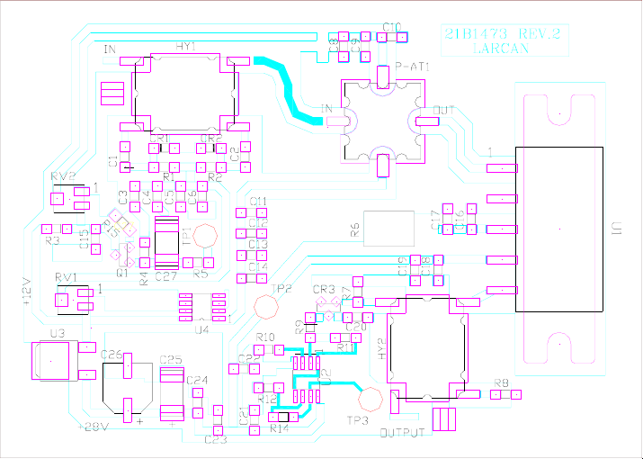
Figure 10 - IPA Assembly, MXD5U
PUB09-03 Rev 0 April 16, 2009 09-03-17 MXD5U Operations and Maintenance
MXD5U OPERATIONS AND MAINTENANCE
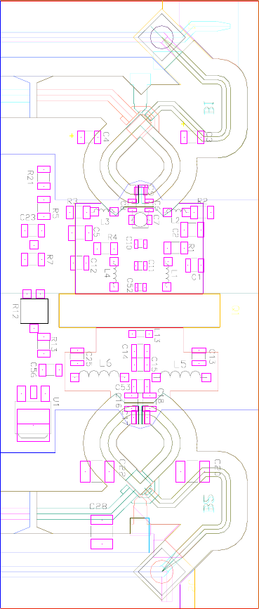
PUB09-03 Rev 0 April 16, 2009 09-03-18 MXD5U Operations and Maintenance
Figure 11 - Amplifier Pallet, MXD5U
MXD5U OPERATIONS AND MAINTENANCE
PUB09-03 Rev 0 16 April, 2009 09-13-19 MXD5U Operations and Maintenance
Figure 12 MXD5U Control Board Assembly

MXD5U OPERATIONS AND MAINTENANCE
NOTES
PUB09-03 Rev 0 16 April, 2009 MXD5U Operations and Maintenance