Larcan MXI1002U Digital Television Translator User Manual Heading 3

Larcan Inc Digital Television Translator Heading 3

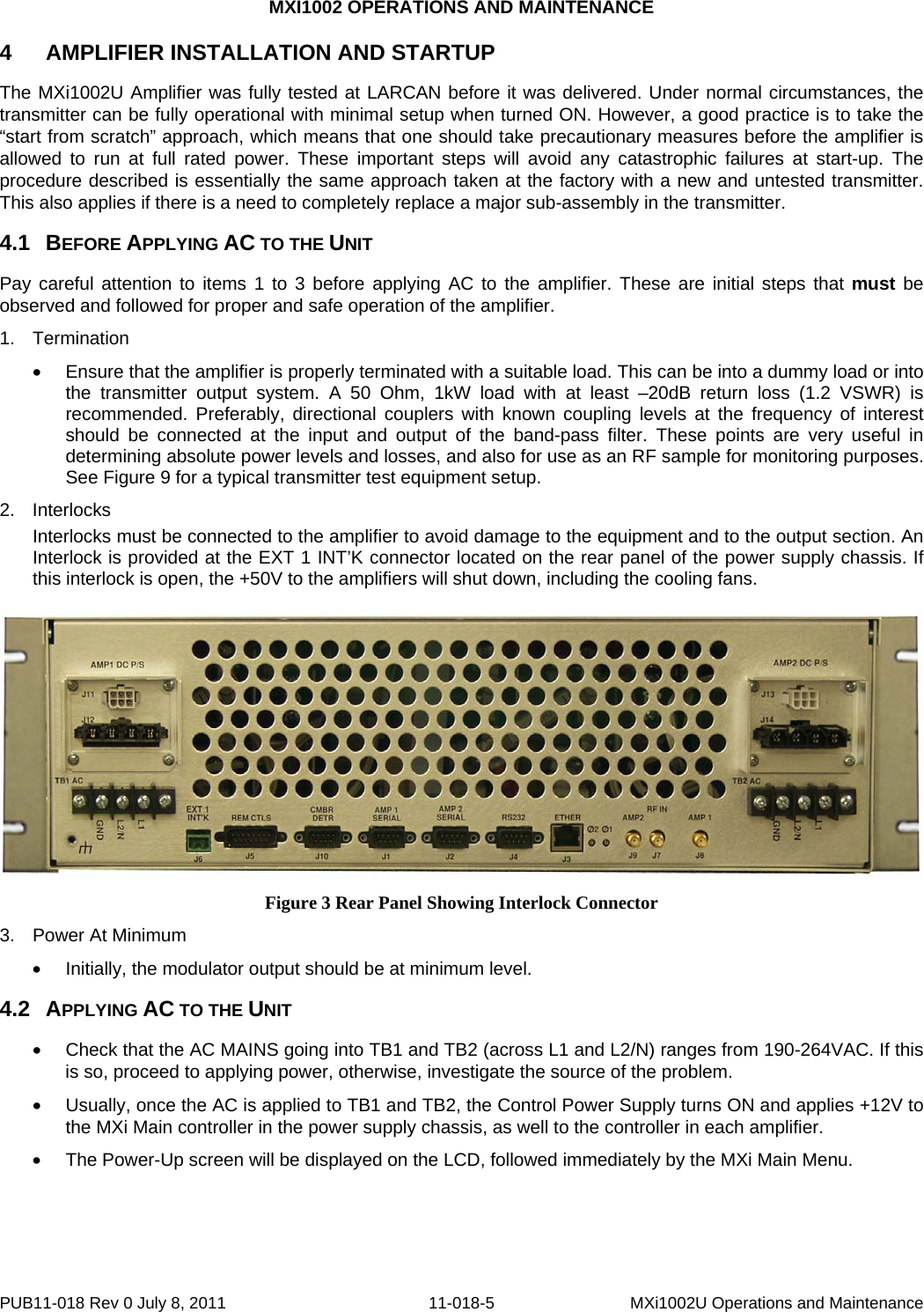
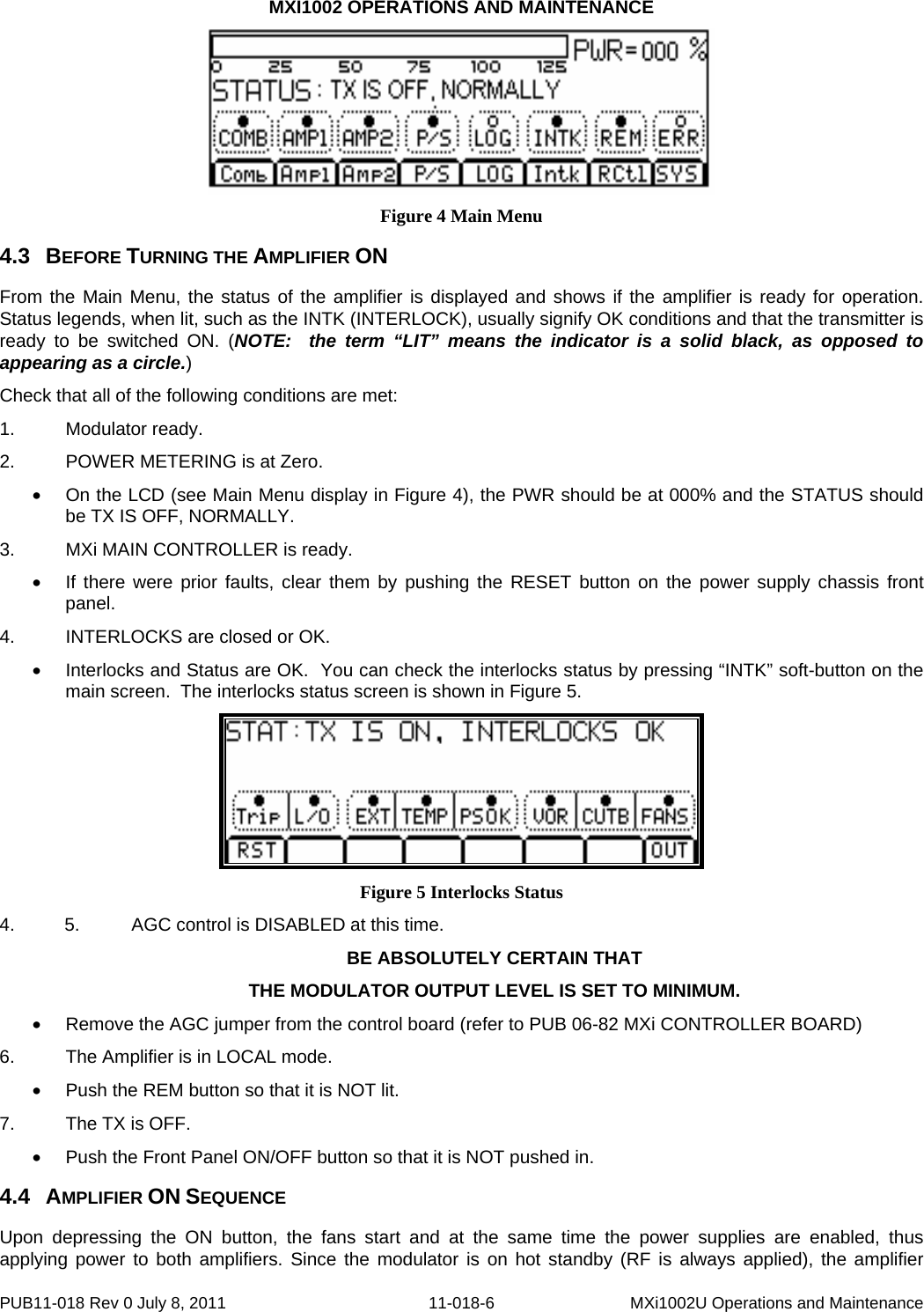
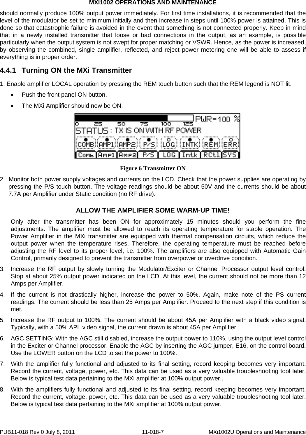
Operations/Maintenance PUB

MXI1002 OPERATIONS AND MAINTENANCE CONTENTS 1 THE MXi1002 TRANSMITTER......................................................................................................................................2 2 MXi1002U AMPLIFIER HEATSINK ASSEMBLY......................................................................................................3 3 MXi AMPLIFIER CONTROLLER.................................................................................................................................4 4 AMPLIFIER INSTALLATION AND STARTUP..........................................................................................................5 4.1 BEFORE APPLYING AC TO THE UNIT ............................................................................................................................5 4.2 APPLYING AC TO THE UNIT..........................................................................................................................................5 4.3 BEFORE TURNING THE AMPLIFIER ON .........................................................................................................................6 4.4 AMPLIFIER ON SEQUENCE............................................................................................................................................6 4.4.1 Turning ON the MXi Transmitter.........................................................................................................................7 4.4.2 TYPICAL DATA read on the LCD.......................................................................................................................8 5 TEST AND TROUBLESHOOTING ...............................................................................................................................9 5.1 BASIC TROUBLESHOOTING TECHNIQUES ......................................................................................................................9 5.1.1 No RF Output.......................................................................................................................................................9 5.1.2 Output Reduced to 25% .......................................................................................................................................9 6 MAINTENANCE.............................................................................................................................................................10 6.1 DAILY.........................................................................................................................................................................10 6.2 MONTHLY...................................................................................................................................................................10 6.3 SEMI-ANNUALLY AND ANNUALLY .............................................................................................................................10 6.4 TRANSMITTER COOLING SYSTEM ...............................................................................................................................10 7 SERVICE..........................................................................................................................................................................11 7.1 REMOVING THE FAN ARRAY.......................................................................................................................................11 7.2 REPLACING THE ENTIRE FAN ARRAY .........................................................................................................................12 8 TEST EQUIPMENT SETUP..........................................................................................................................................13 9 SPECIFICATIONS .........................................................................................................................................................14 9.1 ELECTRICAL ...............................................................................................................................................................14 9.2 ENVIRONMENTAL .......................................................................................................................................................14 9.3 COOLING ....................................................................................................................................................................14 9.4 DIMENSIONS ...............................................................................................................................................................14 9.5 SHIPPING WEIGHT ................................................................................................ERROR! BOOKMARK NOT DEFINED.  FIGURES FIGURE 1 MXI1002 POWER SUPPLY (TOP), AND AMPLIFIERS.......................................................................................................2 FIGURE 2 MXI CONTROLLER........................................................................................................................................................4 FIGURE 3 REAR PANEL SHOWING INTERLOCK CONNECTOR .........................................................................................................5 FIGURE 4 MAIN MENU..................................................................................................................................................................6 FIGURE 5 INTERLOCKS STATUS ....................................................................................................................................................6 FIGURE 6 TRANSMITTER ON ........................................................................................................................................................7 FIGURE 9 BOTTOM VIEW OF MXI...............................................................................................................................................11 FIGURE 10 FAN ARRAY ..............................................................................................................................................................12 FIGURE 12 TEST EQUIPMENT SETUP...........................................................................................................................................13 PUB11-018 Rev 0 July 8, 2011  11-018-1  MXi1002U Operations and Maintenance
MXI1002 OPERATIONS AND MAINTENANCE 1   THE MXi1002 TRANSMITTER The MXi1002 transmitter is usually comprised of a LARCAN Modulator, a Power supply chassis, and two Amplifier chassis.  The RF section of the MXi1002U consists of two identical amplifiers configured to operate in quadrature. Each amplifier is capable of delivering power over 500 Watts Average Digital Power. The output of these amplifiers is fed into a two-way combiner assembly with associated RF detectors which are used for protection and metering purposes. Therefore, in this configuration, the MXi1002 is capable of delivering RF power of up to 1kW Average Digital Power with exceptional performance and reliability. The power supply chassis (top unit shown in Fig.1) contains the main controller board, LCD display, two high efficiency +50VDC switching power supplies and two +12VDC switching power supplies. The +12VDC power supply provides power to the controllers, and the +50V supplies power to the amplifiers.  Figure 1 MXi1002 Power Supply (top), and Amplifiers PUB11-018 Rev 0 July 8, 2011  11-018-2  MXi1002U Operations and Maintenance
MXI1002 OPERATIONS AND MAINTENANCE 2  MXi1002U AMPLIFIER HEATSINK ASSEMBLY Each amplifier assembly consists of a control board, a heatsink assembly that includes two cascaded broadband amplifier stages, a 5-way splitter, a 5-way combiner, and a fuse block. The final amplifier stage (PA) comprises five power amplifiers configured in parallel.  Also mounted on the heatsink located near the output side of the combiner is a thermal switch that protects the amplifier from over temperature conditions. Cooling is achieved using multiple muffin fans located under the hood between the heatsink and the controller. This fan-array assembly is accessible from the bottom of the amplifier assembly, and can be serviced easily by removing 3 screws. PUB11-018 Rev 0 July 8, 2011  11-018-3  MXi1002U Operations and Maintenance
MXI1002 OPERATIONS AND MAINTENANCE 3  MXi AMPLIFIER CONTROLLER The MXi amplifier control board (Assembly 31C1897) is a single-circuit assembly that provides all of the control functions required for the MXi series amplifier on a single circuit board. This board can be configured for a number of different amplifier types, power levels, transmission standards and options.  Figure 2 MXi Controller The board implements status/telemetry for remote monitoring through a rear panel connector that will interface to a typical remote control systems (such as Moseley or Gentner). An RS232 serial port is also provided to allow communication with the main controller located inside the power supply chassis. The MXi control board has RF detectors for forward and reflected power and all the circuitry to support AGC/VSWR/Cutback functions. For complete documentation regarding the Amplifier Controller, see the publication Amplifier Controller.   PUB11-018 Rev 0 July 8, 2011  11-018-4  MXi1002U Operations and Maintenance
MXI1002 OPERATIONS AND MAINTENANCE 4 4.1 AMPLIFIER INSTALLATION AND STARTUP The MXi1002U Amplifier was fully tested at LARCAN before it was delivered. Under normal circumstances, the transmitter can be fully operational with minimal setup when turned ON. However, a good practice is to take the “start from scratch” approach, which means that one should take precautionary measures before the amplifier is allowed to run at full rated power. These important steps will avoid any catastrophic failures at start-up. The procedure described is essentially the same approach taken at the factory with a new and untested transmitter. This also applies if there is a need to completely replace a major sub-assembly in the transmitter. BEFORE APPLYING AC TO THE UNIT Pay careful attention to items 1 to 3 before applying AC to the amplifier. These are initial steps that must be observed and followed for proper and safe operation of the amplifier. 1. Termination • Ensure that the amplifier is properly terminated with a suitable load. This can be into a dummy load or into the transmitter output system. A 50 Ohm, 1kW load with at least –20dB return loss (1.2 VSWR) is recommended. Preferably, directional couplers with known coupling levels at the frequency of interest should be connected at the input and output of the band-pass filter. These points are very useful in determining absolute power levels and losses, and also for use as an RF sample for monitoring purposes. See Figure 9 for a typical transmitter test equipment setup. 2. Interlocks Interlocks must be connected to the amplifier to avoid damage to the equipment and to the output section. An Interlock is provided at the EXT 1 INT’K connector located on the rear panel of the power supply chassis. If this interlock is open, the +50V to the amplifiers will shut down, including the cooling fans.   Figure 3 Rear Panel Showing Interlock Connector 3.  Power At Minimum •  Initially, the modulator output should be at minimum level. 4.2 APPLYING AC TO THE UNIT •  Check that the AC MAINS going into TB1 and TB2 (across L1 and L2/N) ranges from 190-264VAC. If this is so, proceed to applying power, otherwise, investigate the source of the problem. •  Usually, once the AC is applied to TB1 and TB2, the Control Power Supply turns ON and applies +12V to the MXi Main controller in the power supply chassis, as well to the controller in each amplifier. •  The Power-Up screen will be displayed on the LCD, followed immediately by the MXi Main Menu.  PUB11-018 Rev 0 July 8, 2011  11-018-5  MXi1002U Operations and Maintenance
MXI1002 OPERATIONS AND MAINTENANCE  Figure 4 Main Menu 4.3 BEFORE TURNING THE AMPLIFIER ON From the Main Menu, the status of the amplifier is displayed and shows if the amplifier is ready for operation. Status legends, when lit, such as the INTK (INTERLOCK), usually signify OK conditions and that the transmitter is ready to be switched ON. (NOTE:  the term “LIT” means the indicator is a solid black, as opposed to appearing as a circle.) Check that all of the following conditions are met: 1. Modulator ready. 2.  POWER METERING is at Zero. •  On the LCD (see Main Menu display in Figure 4), the PWR should be at 000% and the STATUS should be TX IS OFF, NORMALLY.  3.  MXi MAIN CONTROLLER is ready. •  If there were prior faults, clear them by pushing the RESET button on the power supply chassis front panel. 4.  INTERLOCKS are closed or OK. •  Interlocks and Status are OK.  You can check the interlocks status by pressing “INTK” soft-button on the main screen.  The interlocks status screen is shown in Figure 5.  Figure 5 Interlocks Status 4.  5.  AGC control is DISABLED at this time. BE ABSOLUTELY CERTAIN THAT  THE MODULATOR OUTPUT LEVEL IS SET TO MINIMUM. •  Remove the AGC jumper from the control board (refer to PUB 06-82 MXi CONTROLLER BOARD) 6.  The Amplifier is in LOCAL mode. •  Push the REM button so that it is NOT lit. 7.  The TX is OFF. •  Push the Front Panel ON/OFF button so that it is NOT pushed in. 4.4 AMPLIFIER ON SEQUENCE Upon depressing the ON button, the fans start and at the same time the power supplies are enabled, thus applying power to both amplifiers. Since the modulator is on hot standby (RF is always applied), the amplifier PUB11-018 Rev 0 July 8, 2011  11-018-6  MXi1002U Operations and Maintenance
MXI1002 OPERATIONS AND MAINTENANCE should normally produce 100% output power immediately. For first time installations, it is recommended that the level of the modulator be set to minimum initially and then increase in steps until 100% power is attained. This is done so that catastrophic failure is avoided in the event that something is not connected properly. Keep in mind that in a newly installed transmitter that loose or bad connections in the output, as an example, is possible particularly when the output system is not swept for proper matching or VSWR. Hence, as the power is increased, by observing the combined, single amplifier, reflected, and reject power metering one will be able to assess if everything is in proper order. 4.4.1  Turning ON the MXi Transmitter 1. Enable amplifier LOCAL operation by pressing the REM touch button such that the REM legend is NOT lit. •  Push the front panel ON button. •  The MXi Amplifier should now be ON.  Figure 6 Transmitter ON 2.  Monitor both power supply voltages and currents on the LCD. Check that the power supplies are operating by    pressing the P/S touch button. The voltage readings should be about 50V and the currents should be about 7.7A per Amplifier under Static condition (no RF drive). ALLOW THE AMPLIFIER SOME WARM-UP TIME! Only after the transmitter has been ON for approximately 15 minutes should you perform the fine adjustments. The amplifier must be allowed to reach its operating temperature for stable operation. The Power Amplifier in the MXi transmitter are equipped with thermal compensation circuits, which reduce the output power when the temperature rises. Therefore, the operating temperature must be reached before adjusting the RF level to its proper level, i.e. 100%. The amplifiers are also equipped with Automatic Gain Control, primarily designed to prevent the transmitter from overpower or overdrive condition. 3.  Increase the RF output by slowly turning the Modulator/Exciter or Channel Processor output level control. Stop at about 25% output power indicated on the LCD. At this level, the current should not be more than 12 Amps per Amplifier. 4.  If the current is not drastically higher, increase the power to 50%. Again, make note of the PS current readings. The current should be less than 25 Amps per Amplifier. Proceed to the next step if this condition is met. 5.  Increase the RF output to 100%. The current should be about 45A per Amplifier with a black video signal. Typically, with a 50% APL video signal, the current drawn is about 45A per Amplifier. 6.  AGC SETTING: With the AGC still disabled, increase the output power to 110%, using the output level control in the Exciter or Channel processor. Enable the AGC by inserting the AGC jumper, E16, on the control board. Use the LOWER button on the LCD to set the power to 100%. 7.  With the amplifier fully functional and adjusted to its final setting, record keeping becomes very important. Record the current, voltage, power, etc. This data can be used as a very valuable troubleshooting tool later. Below is typical test data pertaining to the MXi amplifier at 100% output power.. 8.  With the amplifiers fully functional and adjusted to its final setting, record keeping becomes very important. Record the current, voltage, power, etc. This data can be used as a very valuable troubleshooting tool later. Below is typical test data pertaining to the MXi amplifier at 100% output power.  PUB11-018 Rev 0 July 8, 2011  11-018-7  MXi1002U Operations and Maintenance
MXI1002 OPERATIONS AND MAINTENANCE 4.4.2  TYPICAL DATA read on the LCD  Combined COMB  100%  RFL  0.5% AMP1  100%  AMP2  100%   Amplifier FWD  100%  RFL  00.2% AGC  1.0V  CUTB  0.0V   Power Supply PS1  VOLTS  50.0V    PS2  VOLTS  50.0V PS1 CURR  45.0A    PS2 CURR  45.0A PUB11-018 Rev 0 July 8, 2011  11-018-8  MXi1002U Operations and Maintenance
MXI1002 OPERATIONS AND MAINTENANCE 5 5.1 5.1.1 5.1.2 TEST AND TROUBLESHOOTING BASIC TROUBLESHOOTING TECHNIQUES One of the best tools in troubleshooting is knowing what the nominal figures or typical values of the MXi amplifier when it is at its normal performance. If a fault condition occurs, then you can compare the data taken previously with the present conditions and come up with a reasonable conclusion about what is at fault. The following describes some fault conditions and possible solutions. No RF Output  •  Check for proper power supply voltage and current •  Check for the presence of input signal to the modulator •  Ensure the modulator output is present. •  Check for potential connector problems causing either no drive to a module pallet (input connector) or VSWR (output connector) problems. •  Check the fuses on the amplifiers. Output Reduced to 25% If the output is approximately 25%, a possible cause is a total loss of power from one of the amplifiers. The MXi1002 transmitter utilizes a 3dB combiner to combine the power of the two RF amplifiers. If one amplifier produces no output, half of the output of the operating amplifier goes to the output and the other half goes into the reject loads. Similarly, most of the stages in the amplifier have redundancy built in them so that if one fails the output of that stage will be reduced to quarter power (25%).  In most cases there will be a blown fuse on the offending pallet, indicating a shorted FET.  From the control screen a simple measurement of the current drawn by the amplifier in comparison with nominal readings will determine if this condition exists. PUB11-018 Rev 0 July 8, 2011  11-018-9  MXi1002U Operations and Maintenance
MXI1002 OPERATIONS AND MAINTENANCE 6 MAINTENANCE 6.1 6.2 6.3 6.4 Equipment which is regularly and carefully maintained is far less likely to be subject to sudden failure than that which is operated without regard to basic maintenance requirements. A detailed preventive maintenance program should be established to ensure that the original efficiency and picture quality is maintained throughout the life of the equipment. Given reasonable care and attention, the transmitter will provide efficient and reliable service for many years. Preventive maintenance techniques do not necessarily involve extensive dismantling of the various assemblies; on the contrary, this practice is to be discouraged unless a valid reason exists for doing so. Preventive maintenance is more directed at detailed physical inspection and the general observation of the equipment during and after operation, to detect the presence of any abnormality, which, if not corrected, might result in operational failure. In preparing any maintenance program, the frequency and scope of the inspections must be determined and to a great degree will be influenced by site location and the station's market parameters and consequently its hours of operation, equipment configuration, and technical personnel deployment. For example, is the station on the air for 24 hours-a-day? Are there main/standby transmitters and are they attended or unattended? In general, the following routines should form the basis of any maintenance program. DAILY At an attended site, the operator is afforded the opportunity to make frequent checks on the equipment and thereby increase his/her familiarity with its operation. The transmitter log entries made during these checks would include all meter readings, also any irregularity in performance or in picture quality, for later analysis. An unattended site where equipment is operated by remote control and monitored by telemetry and a high quality off-air receiver or demodulator can also be continuously checked for performance by studio technical personnel. MONTHLY In addition to the normal operational tests, thorough physical inspection of every piece of equipment should be made, with all power turned off. All surfaces should be dusted off or wiped down, terminal boards checked for loose connections, and all components examined for any evidence of overheating. Air filter media should be inspected and replaced if necessary. High-pressure air, not over 20psi, can be used with discretion to dislodge dust from inaccessible places. SEMI-ANNUALLY AND ANNUALLY Check all external RF connections for tightness, looking specifically for any discoloration, which might indicate a loose inner connector, flange or sleeve coupling. Test the passive RF system with a transmission test set or network analyzer, if one is available, to identify any potential problems with the antenna or line. Inspect and clean contacts on all switches and contactors; carefully redress contact surfaces if pitted. Check the operation of all interlocks including patch panel, dummy load, air and thermal switches and emergency interlocks (if applicable). TRANSMITTER COOLING SYSTEM All cooling fans in the transmitter are fitted with sealed bearings requiring no lubrication during the lifetime of the motor. Access to the fan assembly is via the bottom of the transmitter.   PUB11-018 Rev 0 July 8, 2011  11-018-10  MXi1002U Operations and Maintenance
MXI1002 OPERATIONS AND MAINTENANCE 7 7.1  SERVICE The MXi contains few user-serviceable parts; the modular surface-mount design makes module replacement and/or factory repair the most efficient repair method. The service most likely to be performed by users is the replacement of the fan array. REMOVING THE FAN ARRAY The MXi fan array consists of four 4” muffin-type fans which are attached to the mounting plate. The mounting plate is secured to the bottom of the MXi chassis with three Phillips head screws.  Figure 7 Bottom View of MXi 1.  Turn the MXi OFF. 2.  Disconnect the AC power from the MXi. 3.  Slide the MXi partially out from the mounting rack. Important: Ensure that the weight of the MXi is fully supported. 4.  With a Phillips screwdriver, remove the five mounting screws on the underside of the MXi. When removing the last screw, be sure to hold the mounting plate in place. 5.  Remove the mounting plate. The fan array is attached to the mounting plate and comes out with the plate. PUB11-018 Rev 0 July 8, 2011  11-018-11  MXi1002U Operations and Maintenance
MXI1002 OPERATIONS AND MAINTENANCE PUB11-018 Rev 0 July 8, 2011  11-018-12  MXi1002U Operations and Maintenance In the event of a fan failure, LARCAN recommends replacing the entire array, as all fans have a similar lifespan. 7.2 R3.  Insert and tighten the five mounting screws. Note: Screws only need to be snug; do not overtighten.  2.  Slide the new fan array into the MXi. The power connection is aligned so that it connects when the mounting plate is fully in place. 1.  Remove the fan array as described in Section 7.1. EPLACING THE ENTIRE FAN ARRAY Figure 8 Fan Array
MXi1002U OPERATIONS AND MAINTENANCE PUB11-018 Rev 0 July 8, 2011  11-018-13    MXi1002U Operations and Maintenance 8  Figure 9 Test Equipment Setup TEST EQUIPMENT SETUP
MXi1002U OPERATIONS AND MAINTENANCE 9 9.1 9.2 9.3 9.4 SPECIFICATIONS Specifications are subject to change without notice. ELECTRICAL AC Line Input ...................................................................................................................190 to 264VAC, 50 to 60Hz Power Consumption, black picture + 10% aural ................................................................................... 5kVA (typical) ENVIRONMENTAL Ambient Temperature .....................................................................................................0°C to +45°C (0°F to 113°F) Humidity ..................................................................................................................................................... 0% to 90% Altitude ..............................................................................................................................................2286 m (7500 ft) COOLING Four 4” muffin fans per amplifier push air through the heatsinks and through the rear panel perforations. DIMENSIONS The Amplifiers, Power Supply, and Modulator, are standard 19" rack wide units. Height  Amplifiers and Power Supply......................................................................................................15.75" (9RU)  Digital Modulator/Upconverter......................................................................................................1.75” (1RU)   Total Height ..........................................................................................................................…17.25” (10RU) Depth is 31" to the back of the 2-way combiner.     PUB11-018 Rev 0 July 8, 2011  11-018-14  MXi1002U Operations and Maintenance
MXi1002U OPERATIONS AND MAINTENANCE NOTES                                    PUB11-018 Rev 0 July 8, 2011    MXi1002U Operations and Maintenance

Navigation menu