Larcan MXI1503U Television Broadcast Translator User Manual control chassis
Larcan Inc Television Broadcast Translator control chassis
Larcan >
Contents
control chassis
MXI1503-2004 CONTROL UNIT
PUB13-09 Rev 1 i
CONTENTS
1 INTRODUCTION.............................................................................................................................................................. 1
2 LCD GUI INTERFACE AND TOUCHPAD ................................................................................................................... 2
2.1 MAIN SCREEN AND TOUCHPAD OPERATIONS ................................................................................................................ 2
2.1.1 COMB Status LED ............................................................................................................................................... 3
2.1.2 AMPS Status LED ................................................................................................................................................ 3
2.1.3 COMSStatus LED ................................................................................................................................................ 3
2.1.4 LOG Status LED .................................................................................................................................................. 3
2.1.5 INTK Status LED ................................................................................................................................................. 3
2.1.6 REM Status LED .................................................................................................................................................. 4
2.1.7 ERR Status LED ................................................................................................................................................... 4
2.1.8 SubMenu Select Buttons ....................................................................................................................................... 4
2.2 COMBINED SCREEN ....................................................................................................................................................... 5
2.2.1 TRIP Status LED .................................................................................................................................................. 5
2.2.2 L/O Status LED .................................................................................................................................................... 5
2.2.3 RF Status LED ..................................................................................................................................................... 6
2.2.4 INTK Status LED ................................................................................................................................................. 6
2.2.5 PS OK Status LED ............................................................................................................................................... 6
2.2.6 COMSStatus LED ................................................................................................................................................ 6
2.2.7 AMPS Status LED ................................................................................................................................................ 7
2.2.8 SubMenu Select Buttons ....................................................................................................................................... 7
2.3 OVERALL AMPLIFIER SCREEN ....................................................................................................................................... 8
2.3.1 Individual Amplifier Screen ................................................................................................................................. 8
2.3.1.1. TRIP Status LED ............................................................................................................................................................... 9
2.3.1.2. L/O Status LED.................................................................................................................................................................. 9
2.3.1.3. INTK Status LED ............................................................................................................................................................ 10
2.3.1.4. PSOK Status LED ............................................................................................................................................................ 10
2.3.1.5. FAN1 Status LED ............................................................................................................................................................ 10
2.3.1.6. FAN2 Status LED ............................................................................................................................................................ 10
2.3.1.7. FAN3 Status LED ............................................................................................................................................................ 10
2.3.1.8. FAN4 Status LED ............................................................................................................................................................ 11
2.3.1.9. SubMenu Select Buttons .................................................................................................................................................. 11
2.3.2 Power Supply Submenu ..................................................................................................................................... 11
2.4 LOGS SCREEN ............................................................................................................................................................. 12
2.5 COMBINED INTERLOCKS SCREEN ................................................................................................................................ 12
2.5.1 AMP1 Interlock Status LED ............................................................................................................................... 13
2.5.2 AMP2 Interlock Status LED ............................................................................................................................... 13
2.5.3 AMP3 Interlock Status LED ............................................................................................................................... 13
2.5.4 AMP4 Interlock Status LED (Only for a MXi2004) ........................................................................................... 13
2.5.5 TRIP Status LED ................................................................................................................................................ 14
2.5.6 L/O Status LED .................................................................................................................................................. 14
2.5.7 EXT1 Interlock Status LED ................................................................................................................................ 14
2.5.8 VOR Status LED ................................................................................................................................................ 14
2.5.9 COMMS Status LED .......................................................................................................................................... 14
2.5.10 SubMenu Select Buttons ..................................................................................................................................... 15
2.6 AMP INTERLOCK SCREEN ............................................................................................................................................ 16
2.6.1 TRIP Status LED ................................................................................................................................................ 16
2.6.2 L/O Status LED .................................................................................................................................................. 16
2.6.3 EXT Status LED ................................................................................................................................................. 17
2.6.4 Temperature Interlock Status LED .................................................................................................................... 17
2.6.5 VOR Status LED ................................................................................................................................................ 17
2.6.6 PSOK Status LED .............................................................................................................................................. 17
2.6.7 Cutback Status LED ........................................................................................................................................... 17
2.6.8 FANS Status LED ............................................................................................................................................... 18
2.6.9 SubMenu Select Buttons ..................................................................................................................................... 18
MXI1503-2004 CONTROL UNIT
PUB13-09 Rev 1 ii
2.7 REMOTE CONTROLS AND RS232 SERIAL SCREEN ....................................................................................................... 19
2.7.1 Remote ............................................................................................................................................................... 20
2.7.2 NewFmt .............................................................................................................................................................. 20
2.7.3 ExtCmd............................................................................................................................................................... 20
2.7.4 SerCmd............................................................................................................................................................... 20
2.7.5 Error .................................................................................................................................................................. 21
2.7.6 SubMenu Select Buttons ..................................................................................................................................... 21
2.8 GENERAL SCREEN ....................................................................................................................................................... 22
2.8.1 Real Time Clock Submenu ................................................................................................................................. 22
2.8.2 SubMenu Select Buttons ..................................................................................................................................... 22
2.9 INTERNET SETUP SCREEN ........................................................................................................................................... 23
2.9.1 SubMenu Select Buttons ..................................................................................................................................... 24
3 FRONT PANEL INTERFACE BOARD ....................................................................................................................... 25
3.1.1 LCD Interface .................................................................................................................................................... 25
3.1.2 Error LED and Reset Control ............................................................................................................................ 26
3.1.3 Front Panel On/Off Control and Status ............................................................................................................. 26
4 MAIN CONTROL BOARD ............................................................................................................................................ 27
4.1 GENERAL LAYOUT AND SUBSYSTEMS ........................................................................................................................ 27
4.1.1 Serial Communications ...................................................................................................................................... 27
4.1.2 RF Metering ....................................................................................................................................................... 28
4.1.2.1. VSWR Protection Circuitry ............................................................................................................................................. 28
4.2 ON/OFF RELAY K4 .................................................................................................................................................... 29
4.2.1 Remote I/O ......................................................................................................................................................... 29
4.2.2 Information Storage ........................................................................................................................................... 29
4.2.3 Remote Controls and Status ............................................................................................................................... 29
4.2.3.1. Combined Remote Controls ............................................................................................................................................. 30
4.2.3.2. Combined Remote Status Outputs ................................................................................................................................... 30
4.2.3.3. Combined Telemetry Outputs .......................................................................................................................................... 30
4.3 INTERCONNECTIONS FROM THE CPU BOARD ................................................................................................ 31
5 +12 V DC CONTROL POWER SUPPLY ..................................................................................................................... 32
6 TROUBLE SHOOTING ................................................................................................................................................. 33
6.1 CHECK THE CONTROL POWER SUPPLY VOLTAGES ...................................................................................................... 33
6.2 THE CPU BOARD IS NOT COMMUNICATING WITH FRONT PANEL BOARD OR TOUCH SCREEN ..................................... 33
6.3 TOTAL LOSS OF CPU FUNCTIONS ............................................................................................................................... 33
6.4 THE REAL-TIME CLOCK DOES NOT RETAIN ITS TIME AFTER POWER OUTAGES .......................................................... 33
6.5 SERVICE DEPARTMENT CONTACT INFORMATION ........................................................................................................ 33
FIGURES
FIGURE 1 MAIN CONTROL UNIT .................................................................................................................................................... 1
FIGURE 2 MAIN MENU SCREEN ..................................................................................................................................................... 2
FIGURE 3 COMBINED POWER SCREEN ........................................................................................................................................... 5
FIGURE 4 AMP1 SUBMENU ............................................................................................................................................................ 8
FIGURE 5 AMP2 SUBMENU ............................................................................................................................................................ 8
FIGURE 6 POWER SUPPLY SUBMENU SCREEN ............................................................................................................................. 11
FIGURE 7 LOGS SUBMENU SCREEN ............................................................................................................................................. 12
FIGURE 8 TRANSMITTER ON, INTERLOCKS OK SCREEN .............................................................................................................. 13
FIGURE 9 AMP1, INTERLOCKS SCREEN ........................................................................................................................................ 16
FIGURE 10 REMOTE CONTROL SUBMENU .................................................................................................................................... 19
FIGURE 11 REAL TIME CLOCK SUBMENU SCREEN ...................................................................................................................... 22
FIGURE 12 INTERNET SETUP SUBMENU SCREEN ......................................................................................................................... 23
FIGURE 13 INTERNET SETUP SUBMENU SCREEN ......................................................................................................................... 24
FIGURE 14 FRONT PANEL BOARD ............................................................................................................................................... 25
FIGURE 15 CPU BOARD SHOWN MOUNTED IN THE CONTROL CHASSIS ...................................................................................... 27
FIGURE 16 MXI FRONT PANEL INTERFACE BOARD ASSEMBLY 21B2537A1 AND SCHEMATIC 21B2537S1 ................................ 35
MXI1503-2004 CONTROL UNIT
PUB13-09 Rev 1 iii
FIGURE 17 MAIN CONTROL BOARD ASSEMBLY – 31C1996A1 ................................................................................................... 36
FIGURE 18 MAIN CONTROL BOARD SCHEMATIC SHEET 1 ........................................................................................................... 37
FIGURE 19 MAIN CONTROL BOARD SCHEMATIC SHEET 2 ........................................................................................................... 38
FIGURE 20 MAIN CONTROL BOARD SCHEMATIC SHEET 3 ........................................................................................................... 39
FIGURE 21 MAIN CONTROL BOARD SCHEMATIC SHEET 4 ........................................................................................................... 40
FIGURE 22 MAIN CONTROL BOARD SCHEMATIC SHEET 5 ........................................................................................................... 41
MXI1503-2004 CONTROL UNIT
PUB13-09 Rev 1 1
1 INTRODUCTION
This publication describes the overall control and monitoring unit for the MXi1503 and MXi2004 Solid State TV
transmitters. The main control chassis contains the Touch Screen User Interface, the Front Panel Interface board,
Master Control board and +12V Control Power Supply.
The main control board (Assembly 31C1972) is a single-circuit assembly that provides all of the communications and
controls to the MXi Amplifiers on a single circuit board. The controller uses a RS-232 connection to communicate with
the Amplifiers. The board implements status/telemetry for remote monitoring through a rear panel connector that will
interface to a typical remote control systems (such as Moseley or Gentner). An RS-232 serial port as well as a RJ45
Ethernet connection is also provided to allow remote monitoring using our In-SiNC Remote Monitoring Software. The
MXi control board has RF detectors for forward and reflected power and all the circuitry to support
AGC/VSWR/Cutback functions.
On the front panel is the LCD touchscreen. This provides status and telemetry readings for the transmitter. From the
LCD you have the ability to raise or lower the power using AGC controls. You can also enable or disable the remote
controls and setup your Ethernet address or serial stream communications.
Figure 1 Main Control Unit
MXI1503-2004 CONTROL UNIT
PUB13-09 Rev 1 2
2 LCD GUI INTERFACE AND TOUCHPAD
The user interface to the transmitter is mainly accomplished with the front panel LCD that incorporates a touchpad as
an integral part of the unit. The touchpad consists of a thin membrane attached to the LCD surface which implements
a software-driven menu selection system. The LCD has the capability of displaying a number of different screens,
which are selected by the operator via the touchpad.
Each of the separate display screens (called Menus) is detailed in the following subsections along with their respective
touchpad menu options. When the MXi transmitter is first powered on or returns from an AC power outage, the LCD
displays a screen [Power Up Screen] that only shows for a few seconds and describes the particular transmitter that
this MXi is configured for. Note that there are no touchpad menu options on this screen, since it only displays for a
few seconds. After these seconds have passed, the MXi proceeds into the Main Menu screen described in the next
section.
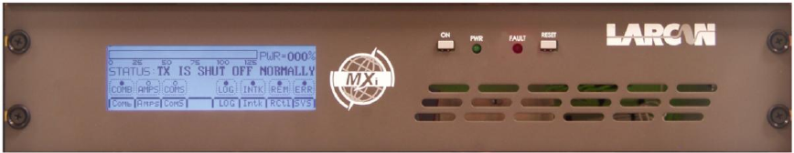
2.1 MAIN SCREEN AND TOUCHPAD OPERATIONS
The Main Menu screen as shown below gives the operator all of the most pertinent values and status to verify the
operation of the transmitter. This screen is the one that is normally left displayed when no maintenance or diagnostic
checks are being performed. It is from this Main screen that all of the other submenu screens can be accessed. If the
operator has switched to another submenu, it is recommended that the LCD is returned to the Main screen, since this
shows an overview of the system operation.
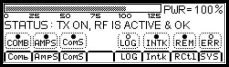
Figure 2 Main Menu Screen
The Main screen can be subdivided into four distinct sections, the main forward RF power at the top line, the
transmitter status on the second line, the individual subsystem status on the third line and the submenu options on the
fourth and last line.
The first line shows the forward RF power that the transmitter is currently generating. This is the power that is actually
being sent out to the antenna or system load. There are two elements that show the same information but in different
formats. The bar graph gives a graphic display of the RF power output level and is calibrated for 100% at the
transmitter’s rated output power. The bar graph will display up to 125% but it is not recommended that the operator
increase the power beyond the rated power without prior approval from LARCAN field service. When the power
exceeds 110%, the bar graph becomes more solid and darker in the area above 110% to indicate that an overpower
condition is present.
The same information is provided to the left of the bar graph in a three-digit display, which shows the current power
output. When calibrating or setting up the transmitter, this three-digit display value should be used as a reference for
the current transmitter power (not the bar graph). This display has a maximum value of 169% power when the
transmitter detectors are set up for a DC output of 4.0 at full power. This value is derived from the fact that the detector
can output a maximum of 5.0VDC to the telemetry circuits, which translates to an output power of 169%. Of course,
this is a maximum display value on the LCD fixed by circuit constraints and the operator should never be approaching
this type of power level with the transmitter. If a display of 169% is indeed shown, then either there is a problem with
the detector or the power of the transmitter is in fact exceeding 169% and should be attended to immediately.
The second line of the LCD shows the current state of the transmitter and any important errors that are current. This
line typically tells the operator if the transmitter has been asked to be in the ON state. The transmitter is placed in the
ON state either by the local front panel ON button or by a remote ON command. If the transmitter has been turned off
by the operator, the LCD reports that the transmitter is OFF normally (i.e., it was not due to an error).
If an error condition has occurred that caused the transmitter to shut down, the LCD displays that the transmitter is
OFF and then shows what the error condition is that has caused the shutdown. As an example, if the External#1
interlock is open, the LCD displays TX IS OFF, EXT1 INTERLOCK OPEN.
MXI1503-2004 CONTROL UNIT
PUB13-09 Rev 1 3
The third line of the display has a number of status lights with a legend describing the particular status underneath and
all enclosed in a dashed line box. When the light is fully darkened, it indicates that this particular status is true. When
the light is hollow, it indicates that this particular status is false. Each status is detailed below.
2.1.1 COMB Status LED
This status represents the state of the combined RF output of the MXi transmitter.
Lit when the Tx is ON and Output Power OK, or when Tx is Off but Ext1 Intk and VSWR Lockout are OK.
Not lit when RF power is low or either Ext1 Intk is open or a VSWR Lockout has occurred.
2.1.2 AMPS Status LED
This is a combined status that indicates the condition of the RF amplifiers.
Lit when the Amp is ON and Output Power OK or Amp is Off but Thermal Interlock and VSWR Lockout are
OK.
Not lit when RF power is low or either Thermal Intk is open or a VSWR Lockout has occurred.
2.1.3 COMSStatus LED
Status that indicates the state of communications to the RF amplifiers.
The amplifier(s) report their operating parameters to the central control unit via a RS232 serial stream. The central
control monitors this stream and will indicate an error if the amplifier stops communicating. This communications must
be operating whether the amplifier RF output is ON or OFF.
Lit when Comms is OK to all Amplifiers.
Not lit when Comms is lost to a single or all Amplifiers
2.1.4 LOG Status LED
Status that shows that there are current entries in the LOG file.
Lit whenever one or more LOG entries are currently in the LOG file via the LOG submenu.
Note these may not be new LOG entries, if the operator checks the LOG file but does not clear it. The log entries
status remains lit even if there are no new Logs. The operator should clear the Logs once viewed so that this Log
status indicates a new Log entry.
Not Lit when there are no current Log entries
2.1.5 INTK Status LED
Status that indicates the interlocks to the RF amplifier are all operating properly.
Lit when interlocks Ext1, VSWR Trip and VSWR Lockout are closed (i.e., OK).
Not lit when or one of the interlocks are opened.
MXI1503-2004 CONTROL UNIT
PUB13-09 Rev 1 4
If this status LED is not lit, then the operator should then check the INTK submenu to determine the source of the
problem. Note that the same individual interlock status can be found on the other submenus as well, but the INTK
submenu is a place where all the individual interlocks are displayed in one place.
2.1.6 REM Status LED
Remote Status for the remote controls, operator controlled via the REM submenu.
Lit when the system is in REMOTE mode and enables remote commands.
Not lit when in LOCAL mode and remote commands are disabled.
2.1.7 ERR Status LED
Status that shows an error either is current or has occurred since last check. This is a composite of the other status
and is a general indication that something is wrong. One of the error conditions is VSWR Trip, which is a saved status.
The VSWR Trip indicates that a VSWR condition had occurred (but may no longer be present). The operator must
press the front panel reset button (or issue a reset command remotely) to clear the VSWR Trip condition.
The user should check the AMP screens and the Interlock screen to check the source of the error.
Lit when both Amps are communicating, Ext1 is closed, VSWR Trip and VSWR Lockout are not present.
Not lit if either Amp is not communicating, Ext1 is open, VSWR Trip or VSWR Lockout have occurred.
2.1.8 SubMenu Select Buttons
The fourth line of the LCD holds select buttons that will cause the LCD to jump to different submenu screen that
provides more detailed information on a certain aspect of the MXi operations. Each submenu screen has an ‘OUT’
button that allows the user to return to this main screen.
The submenu select buttons with a brief description is given below:
COMB = Combined Submenu, Shows combined powers, Agc Reference and Amp1/2 forward powers
AMPS = Amplifier Submenu, Allows to you select which of the Amplifiers you wish to view
COMS = Shows the status of the Communication to each Amplifier
LOG = Log Submenu, Give access to log entries recorded by the system
INTK = Interlock Submenu, Shows the current status of the system interlocks
RCTL = Remote Control Submenu, Remote/Local controls, Command counts and Baud Rate selection
SYS = General System Submenu, System status and configuration parameters and Real Time Clock
MXI1503-2004 CONTROL UNIT
PUB13-09 Rev 1 5
2.2 COMBINED SCREEN
The Combined RF Amplifier submenu is entered by pressing the COMB submenu button on the main LCD screen.
This submenu displays all the various power, status and controls for the combined RF output. Each display item and
control is described as to its meaning and function.
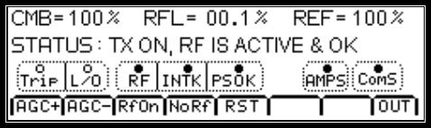
The LCD displays a typical COMB submenu as follows:
Figure 3 Combined Power Screen
The first line shows the combined forward power denoted as CMB that represents the total output RF power from the
transmitter and would be the same value that is displayed on the Main LCD menu. This is represented as a percentage
of the full rated output power of the transmitter.
The second item of the first line shows the reflected power from the transmitter. This represents the total power that is
being reflected back from the RF output system into the transmitter. The maximum amount of power that should be
displayed is 10.0%, since the VSWR protection circuit shuts down the amplifier whenever the reflected power exceeds
10.0%. The expected reflected power would normally be under 1.5% and a value higher than this indicates an issue
with the RF output system. When the reflected power increases, the amplifier automatically cuts back the forward
power. When a value of 1% or higher is shown on the RFL power reading, a FWD power reading of less than 100%
would be expected.
The final item on the first line is AGC reference level. This is the desired power level that the automatic gain control of
each amplifier will try to maintain at its output. Note that the main controller does not actually perform the AGC
function but sends this AGC reference level to each of the amplifiers via the RS232 communications and the individual
amplifiers will then use this level as a reference for their own AGC control circuitry.
The second line of the display shows the current status of the transmitter, it displays the same state as what is shown
on the main screen.
The third line of the display has a number of status lights with a legend describing the particular status underneath and
all enclosed in a dashed line box. When the light is fully darkened, it indicates that this particular status is true. When
the light is hollow, it indicates that this particular status is false. Certain related status are grouped together in the same
box. The purpose of these statuses is to point the operator to the area that is currently causing the RF transmitter to be
shut down. Each status is detailed as follows.
2.2.1 TRIP Status LED
VSWR Trip Status
Lit when the system has seen at least one VSWR trip, can be reset by operator using LCD touchpad, front panel
reset button or a remote reset command
Not lit when there have been no VSWR trips since the last time this was cleared.
Note that this does not mean that there is a current VSWR trip but that one did occur.
The operator may have this status as true (with no Lockout status) and still have the RF amplifier active.
2.2.2 L/O Status LED
VSWR Lockout Status
Lit when the system has seen three VSWR trips in less than 1 minute.
MXI1503-2004 CONTROL UNIT
PUB13-09 Rev 1 6
When a VSWR trip occurs, the MXi controller will reset the trip automatically and repower the RF amplifier. If three
trips occur within 1 minute, the Lockout status is set and the RF amplifier will remain OFF. The Lockout status can be
reset by the operator using LCD touchpad, front panel reset button or a remote reset command.
Not lit when there have been no VSWR trips since the last time this was cleared.
2.2.3 RF Status LED
If the transmitter is ON, then the output power telemetry cannot fall more than 160 mV under the AGC reference level.
That is if the AGC is set for 100% power (voltage of 4.0v), then the RF LED will be lit only if the output power telemetry
is higher than 3.84v (or 92 % power). Note that the output power is proportional to the square of the telemetry voltage.
This indicates that the transmitter is outputting a power level that is near to the desired output power level.
Lit when transmitter is ON and RF power is near the set AGC reference level
Not lit when the transmitter is either OFF or the RF output power is low.
2.2.4 INTK Status LED
Interlock inputs that affect the RF amplifier are all closed and OK.
Lit when interlocks VSWR Lockout, VSWR Relay and Ext1 are closed (i.e., OK).
Not lit when at least one of the above interlocks are opened.
The VSWR Lockout is related to the VSWR Relay status in that both are driven off the state of the VSWR Relay on the
MXi board. When a VSWR condition occurs, the VSWR Relay is opened momentarily to allow the system to clear any
VSWR condition and try to restart the transmitter.
During this time the VSWR Relay interlock will be open (false), but the VSWR Lockout status will still be OK since less
than 3 VSWR trips have been detected. Once more than 3 trips have been detected in the 1 minute time frame then
the VSWR relay will not be reset and both the VSWR LockOut and VSWR Relay will be open.
2.2.5 PS OK Status LED
Status that indicates the +50V power supply to the RF amplifiers are currently ON and are operating properly
Lit when the Power Supplies are ON, the voltage is at +50V
Not lit when the Power Supplies are either OFF or has some operational problems.
2.2.6 COMSStatus LED
Status that indicates the state of communications to the RF amplifiers.
The amplifier(s) report their operating parameters to the central control unit via a RS232 serial stream. The central
control monitors this stream and will indicate an error if the amplifier stops communicating. This communications must
be operating whether the amplifier RF output is ON or OFF.
Lit when Comms is OK to all Amplifiers.
Not lit when Comms is lost to a single or all Amplifiers
MXI1503-2004 CONTROL UNIT
PUB13-09 Rev 1 7
2.2.7 AMPS Status LED
This is a combined status that indicates the condition of the RF amplifiers.
Lit when the Amp is ON and Output Power OK or Amp is Off but Thermal Interlock and VSWR Lockout are
OK.
Not lit when RF power is low or either Thermal Intk is open or a VSWR Lockout has occurred.
2.2.8 SubMenu Select Buttons
The fourth line of the LCD hold select buttons that will control combined operation plus allow access to a second level
of submenu. The select buttons with a brief description is given below:
AGC+ = Increases the transmitter AGC reference level in 1-2% steps
AGC- = Decreases the transmitter AGC reference level in 1-2% steps
RfON = Restores the AGC reference level to previous point. Only valid after an RfOFF command.
NoRF = Sets the AGC reference level to zero & stores old level.
Note AGC can only reduce RF to a minimum of around 10-20%
RST = Reset Control will issue a VSWR Trip reset command
OUT = Returns LCD to the main LCD screen.
MXI1503-2004 CONTROL UNIT
PUB13-09 Rev 1 8
2.3 OVERALL AMPLIFIER SCREEN
The RF Amplifier submenu is entered by pressing the AMPS submenu button on the main LCD screen.
The main AMPS submenu displays the forward power of each of the amplifiers on the top lines and an overall status
indication for each amplifier. If the amplifier is operating ok with no problems the status LED will be lit, it will be not lit
when there is a problem.
At the bottom of the screen is the button that will take you into each of the individual amplifier submenu.
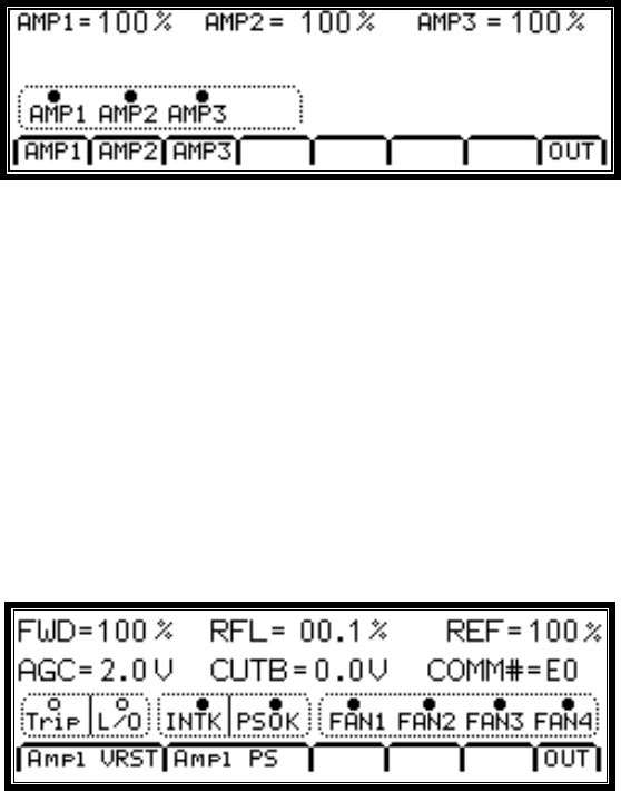
Figure 4 Amps Submenu
2.3.1 Individual Amplifier Screen
Each of the amplifier screens look the same so only Amp 1 screen is displayed below.
This submenu displays all the various power, status and controls for the RF amplifier. Each display item and control is
described as to its meaning and function.
Each Amplifier submenu is identical except for the labels on the buttons on line four of the LCD display which denotes
the current Amplifier VSWR Reset button and PS submenu. For example if you went to Amplifier 2 screen it would
display ‘Amp2 VRST’ and “Amp2 PS” when the Amp2 screen is being accessed.
The LCD displays a typical AMPS submenu as follows:
Figure 5 Amp1 Submenu
The first item displayed on the first line is the forward power denoted as FWD that represents the total output RF power
from the amplifier and would be the same value that is displayed on the overall amplifier menu. This is represented as
a percentage of the full rated output power of the transmitter.
The second item on the first line is the reflected power from the amplifier. This represents the total power that is being
reflected back from the output combiner back into the amplifier. The maximum amount of power that should be
displayed is 10.0%, since the VSWR protection circuit shuts down the amplifier whenever the reflected power exceeds
10.0%. The expected reflected power would normally be under 1.5% and a value higher than this indicates a problem
with the RF output system. When the reflected power increases, the amplifier automatically cuts back the forward
power. When a value of 1% or higher is shown on the RFL power reading, a FWD power reading of less than 100%
would be expected.
MXI1503-2004 CONTROL UNIT
PUB13-09 Rev 1 9
The third item on the first line is the AGC reference level. This is the desired power level that the automatic gain
control of each amplifier will try to maintain at its output. Note that the main controller does not actually perform the
AGC function but sends this AGC reference level to each of the amplifiers via the RS232 communications and the
individual amplifiers will then use this level as a reference for their own AGC control circuitry.
The first item of the second line shows the telemetry of the AGC voltage that the MXi controller uses to regulate the
power generated by the RF amplifier and maintain it at 100% (or an other operator defined level). The AGC voltage
sent to the RF amplifier can range from 0 to 10VDC, however, the A/D converter of the MXi CPU chip can only receive
a level of 0 to 5VDC. To satisfy this requirement, the hardware circuitry divides the actual AGC control voltage by two
and displays this half value on the LCD.
The second item of the second line shows the telemetry of the Cutback voltage that the MXi controller uses to reduce
the power generated by the RF amplifier in the presence of reflected power (VSWR condition). The Cutback voltage
sent to the RF amplifier can range from 0 to 10VDC, however, the A/D converter of the MXi CPU chip can only receive
a level of 0 to 5VDC. To satisfy this requirement, the hardware circuitry divides the actual Cutback control voltage by
two and displays this half value on the LCD.
Note that when Cutback is present, the AGC voltage will have both an AGC component and a CUTBACK component.
That is, if the amplifier was set for 100% power and there is no VSWR, the LCD would show something like
AGC=0.45V and CUTB=0.01V. When there is a VSWR condition, the LCD would show something like AGC=1.45V
and CUTB=1.00V. The AGC voltage displayed is a composite of 0.45 volts of AGC action and 1.0V of cutback action.
The third item of the second line shows serial stream number in hexadecimal that will range from $00 to $FF. Each
time the amplifier sends a new serial stream to the main controller, it will increment this number to help the main
controller to identify a new set a data from the previous one. In normal operation, this number should be incrementing
around once per second. Once the value reaches $FF the next stream will wrap this counter back to $00 again.
The third line of the display has a number of status lights with a legend describing the particular status underneath and
all enclosed in a dashed line box. When the light is fully darkened, it indicates that this particular status is true. When
the light is hollow, it indicates that this particular status is false. Certain related status are grouped together in the same
box. The purpose of these statuses is to point the operator to the area that is currently causing the RF amplifier to be
shut down. Each status is detailed as follows.
2.3.1.1. TRIP Status LED
VSWR Trip Status
Lit when the system has seen at least one VSWR trip, can be reset by operator using LCD touchpad.
Not lit when there have been no VSWR trips since the last time this was cleared.
Note that this does not mean that there is a current VSWR trip but that one did occur.
The operator may have this status as true (with no Lockout status) and still have the RF amplifier active.
2.3.1.2. L/O Status LED
VSWR Lockout Status
Lit when the system has seen three VSWR trips in less than 1 minute.
When a VSWR trip occurs, the MXi controller will reset the trip automatically and repower the RF amplifier.
If three trips occur within 1 minute, the Lockout status is set and the RF amplifier will remain OFF.
The Lockout status can be reset by the operator pushing the RST button on the LCD touchpad.
Not lit when there have been no VSWR trips since the last time this was cleared.
MXI1503-2004 CONTROL UNIT
PUB13-09 Rev 1 10
2.3.1.3. INTK Status LED
Interlock inputs that affect the RF amplifier are all closed and OK. The amplifier Ext1 interlock is the last in the chain
and will only be closed if all the other previous interlocks are also true (these include Vswr, Thermal, TxSw).
Lit when transmitter is ON and all interlocks are closed (i.e., OK).
Not lit when the transmitter is either OFF or one of the interlocks are opened.
If the transmitter has indeed been set to ON and the front panel ON LED is lit, an error is present.
The operator should then check the INTK submenu to determine the source of the problem.
2.3.1.4. PSOK Status LED
Power Supply OK status, the 50V power supply to the RF amplifier is currently ON and is operating properly.
Lit when the Power Supply is ON. The P/S voltage, current and status are all OK.
Not lit when the Power Supply is either OFF or has some operational problems.
If the Power Supply has indeed been set to ON and the front panel ON LED is lit, an error is present.
2.3.1.5. FAN1 Status LED
Status that shows if FAN1 is currently operational.
When the transmitter is turned ON, all the fans are turned on.
Lit when fan rotational status is true, this only happens if the fan is actually rotating.
Not lit when the fan is not rotating; if the other fans are OK, this indicates a failure.
2.3.1.6. FAN2 Status LED
Status that shows if FAN2 is currently operational.
When the transmitter is turned ON, all the fans are turned on.
Lit when fan rotational status is true, this only happens if the fan is actually rotating.
Not lit when the fan is not rotating; if the other fans are OK, this indicates a failure.
2.3.1.7. FAN3 Status LED
Status that shows if FAN3 is currently operational.
When the transmitter is turned ON, all the fans are turned on.
Lit when fan rotational status is true, this only happens if the fan is actually rotating.
Not lit when the fan is not rotating; if the other fans are OK, this indicates a failure.
MXI1503-2004 CONTROL UNIT
PUB13-09 Rev 1 11
2.3.1.8. FAN4 Status LED
Status that shows if FAN4 is currently operational.
When the transmitter is turned ON, all the fans are turned on.
Lit when fan rotational status is true, this only happens if the fan is actually rotating.
Not lit when the fan is not rotating; if the other fans are OK, this indicates a failure.
2.3.1.9. SubMenu Select Buttons
The fourth line of the LCD contains three buttons:
Amp1 VRST = VSWR Reset Control for Amplifier #1
Amp1 PS = Amplifier Power Supply Submenu
OUT = Returns LCD to the Overall Amplifier LCD Screen.
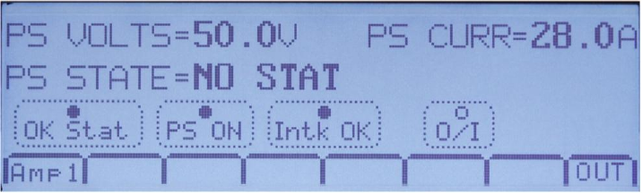
2.3.2 Power Supply Submenu
The Power Supply submenu is entered by pressing the P/S submenu button on the Amplifiers LCD screen.
This submenu displays the voltage and current for the +50V power supplies for the particular amplifier being viewed
The LCD displays a typical P/S submenu as shown below.
Figure 6 Power Supply Submenu Screen
For each power supply the measured telemetry values for the power supply voltage and current are displayed.
At the bottom of the screen in the menu bar the first button is just a display of which amplifiers power supply you are
viewing and does not have any action associated with it. There is only one menu button that works and it is the
rightmost button labeled OUT which exits this submenu. When the operator is finished in the submenu, an OUT
command returns to the previous screen.
OUT = Returns LCD to the individual Amplifier LCD Screen.
MXI1503-2004 CONTROL UNIT
PUB13-09 Rev 1 12
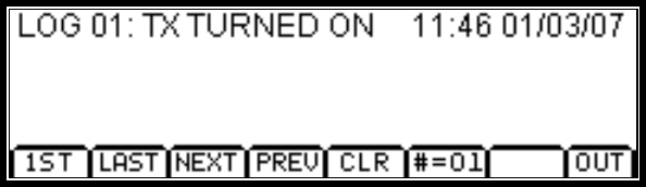
2.4 LOGS SCREEN
The LOGS submenu is entered by pressing the LOGS submenu button on the main LCD screen.
This submenu begins by displaying the first three log entries that are stored in the internal log table. If there are fewer
than three entries, only those one or two log entries are displayed. The first three lines of the display are used to
display log entries and the last line is used for menu button options. The LCD displays a typical LOGS submenu as
follows:
Figure 7 Logs Submenu Screen
The logs are displayed up to three at a time, in the order in which they were detected in the controller. That is, the logs
are in chronological order from the time they were received. The seventh menu button on the fourth line of the LCD
shows the total number of log entries [our example shows entries #=01].
A maximum of 99 log entries can be held in the log table. If the log table already contains 99 entries and a new log has
occurred, the oldest log is discarded and the new log is entered into the table. In this manner the log table will hold the
99 most recent logs.
In the fourth menu button line of the LCD, the first four button selections (from the left side) allow the operator to
navigate through the log table when there are more than three logs. If there are three logs or less, all the entries are
already displayed on the LCD.
The first menu button is labeled 1ST and causes the display to return to the beginning of the log table and display the
first three entries.
The second menu button is labeled LAST and causes the display to jump to the end of the log table and display the
last three entries.
The third menu button is labeled NEXT and causes the display to scroll down one log entry. If the LCD was displaying
LOGS 2-4, then pressing NEXT displays LOGS 3-5.
The fourth menu button is labeled PREV and causes the display to scroll up one log entry. If the LCD was displaying
LOGS 2-4, then pressing PREV displays LOGS 1-3.
The fifth menu button is labeled CLR and causes the log table to be cleared and the LCD will have no logs to display
and the count will revert back to zero #=00. As noted previously, the log count is located in the seventh menu button
position. Pressing this button does not perform any function.
The eighth menu button is labeled OUT and causes the LCD screen to return to the Main Menu.
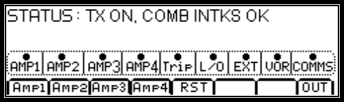
2.5 COMBINED INTERLOCKS SCREEN
The Combined Interlocks submenu is entered by pressing the INTK submenu button on the main LCD screen.
This submenu displays all the various interlocks for the RF amplifier. Each display item and control is described as to
its meaning and function.
The LCD displays a typical INTK submenu as follows:
MXI1503-2004 CONTROL UNIT
PUB13-09 Rev 1 13
Figure 8 Transmitter On, Interlocks OK Screen
The first line of the LCD shows the transmitter ON/OFF status and the resulting interlock status. If the transmitter has
been turned ON and the Interlocks are OK, then the RF amplifier is indeed receiving the +50V power feed..
The third line of the display has a number of status lights with a legend describing the particular status underneath and
all enclosed in a dashed line box. When the light is fully darkened, it indicates that this particular status is true and that
interlock is closed (OK). When the light is hollow, it indicates that this particular status is false and the interlock is open
(BAD). Each status is detailed below.
2.5.1 AMP1 Interlock Status LED
The status for the Amp1 interlock is determined from values sent from Amplifier #1 to the main controller via the serial
stream. The communications from amplifier #1 must be good for this status to show OK.
Lit when Amp1 Comms is OK, Amp1 Ext1 and VSWR Interlocks are closed.
Not lit when either Amp1 Comms is bad, Amp1 Ext1 is open or Amp1 VSWR Interlock is open
2.5.2 AMP2 Interlock Status LED
The status for the Amp2 interlock is determined from values sent from Amplifier #2 to the main controller via the serial
stream. The communications from Amplifier #2 must be good for this status to show OK.
Lit when Amp2 Comms is OK, Amp2 Ext1 and VSWR Interlocks are closed.
Not lit when either Amp2 Comms is bad, Amp2 Ext1 is open or Amp2 VSWR Interlock is open
2.5.3 AMP3 Interlock Status LED
The status for the Amp3 interlock is determined from values sent from Amplifier #3 to the main controller via the serial
stream. The communications from Amplifier #3 must be good for this status to show OK.
Lit when Amp3 Comms is OK, Amp3 Ext1 and VSWR Interlocks are closed.
Not lit when either Amp3 Comms is bad, Amp3 Ext1 is open or Amp2 VSWR Interlock is open
2.5.4 AMP4 Interlock Status LED (Only for a MXi2004)
The status for the Amp4 interlock is determined from values sent from Amplifier #4 to the main controller via the serial
stream. The communications from Amplifier #4 must be good for this status to show OK.
Lit when Amp4 Comms is OK, Amp4 Ext1 and VSWR Interlocks are closed.
Not lit when either Amp4 Comms is bad, Amp4 Ext1 is open or Amp4 VSWR Interlock is open
MXI1503-2004 CONTROL UNIT
PUB13-09 Rev 1 14
2.5.5 TRIP Status LED
VSWR Trip Status
Lit when there have been no VSWR trips since the last time this was cleared.
Not lit when the system has seen at least one VSWR trip.
Note that this does not mean that there is a current VSWR trip but that one did occur.
The operator may have this status as true (with no Lockout status) and still have the RF amplifier active.
This can be reset by the operator using the LCD touchpad button RST or by the front panel Reset button.
2.5.6 L/O Status LED
VSWR Lockout Status
Lit when there is no VSWR Lockout condition.
Not lit when the system has seen three VSWR trips in under 1 minute.
When a VSWR trip occurs, the MXi controller will reset the trip automatically and repower the RF amp. If three trips
occur within 1 minute, the Lockout status is set and the RF amplifier will remain Off. The Lockout status can be reset
by the operator pushing the RST button on the LCD touchpad.
2.5.7 EXT1 Interlock Status LED
This is the external #1 interlock that is accessed from the rear panel of the main control chassis. The main controller
verifies that this interlock is closed before and transmitter ON command is issued to the individual amplfiers. Often this
interlock is used to validate the state of the RF output system or site condition.
Lit when the external #1 interlock is closed.
Not lit when the external #1 interlock is open. Either there is a fault or the transmitter has been turned off.
2.5.8 VOR Status LED
Video Operated Relay Control, this is used in some configurations to control the ON/OFF transmitter state.
When enabled or configured, the transmitter will respond to the VOR input by turning ON or OFF.
This function is client specific and would not be enabled in most transmitter configurations.
Most sites can safely ignore this status unless it has been specifically requested by the customer.
Lit when VOR is present and the transmitter is enabled to be ON.
Not lit when VOR is off, the transmitter is OFF only if the VOR function is enabled.
2.5.9 COMMS Status LED
Communications to amplifiers
Lit when all amplifiers are properly sending their serial data to the main controller
Not lit when either amplifier has failed to send valid serial data within 5 seconds.
MXI1503-2004 CONTROL UNIT
PUB13-09 Rev 1 15
2.5.10 SubMenu Select Buttons
The fourth line of the LCD has several button selections which are available to the user. Four buttons select the
amplifier interlock submenus (Three in the case of an MXi1503); one button is for VSWR reset and the last exits this
menu.
AMP1 = Selects the Amplifier1 Interlock Submenu LCD Screen.
AMP2 = Selects the Amplifier2 Interlock Submenu LCD Screen
AMP3 = Selects the Amplifier3 Interlock Submenu LCD Screen
AMP4 = Selects the Amplifier4 Interlock Submenu LCD Screen (Only for a MXi2004)
RST = Resets the VSWR trips (on the main controller and both amplifiers).
OUT = Returns LCD to the main LCD Screen.
MXI1503-2004 CONTROL UNIT
PUB13-09 Rev 1 16
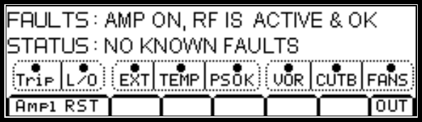
2.6 AMP INTERLOCK SCREEN
The Amplifier Interlock submenu is entered by pressing the appropriate AMP submenu button on the Combined
Interlock LCD submenu screen. This is a level 2 submenu which is accessed from a level 1 submenu which in turn is
accessed from the level 0 main screen.
This submenu displays all the various interlock conditions for the amplifier. Each display item and control is described
as to its meaning and function.
The AMP submenus are identical except the first button on line four of the LCD display will denote ‘Amp2 RST’ when
the Amp2 screen is being accessed, ‘Amp3 RST’ when the Amp3 screen is being accessed and in the case of a
MXi2004, ‘Amp4 RST’ when the Amp4 screen is being accessed.
This submenu displays all the various interlocks for the RF amplifier. Each display item and control is described as to
its meaning and function.
The LCD displays a typical INTK submenu as follows:
Figure 9 Amp1, Interlocks Screen
The first line gives a status of whether the amplifier is ON or OFF and if any fault conditions exist.
The second line gives a more detailed description of any existing amplifier faults
The third line of the display has a number of status lights with a legend describing the particular status underneath and
all enclosed in a dashed line box. When the light is fully darkened, it indicates that this particular status is true and that
interlock is closed (OK).
When the light is hollow, it indicates that this particular status is false and the interlock is open (BAD). Certain related
status are grouped together in the same box. The purpose of these statuses is to point the operator to the area that is
currently causing the RF amplifier to be shut down. Each status is detailed below.
2.6.1 TRIP Status LED
VSWR Trip Status
Lit when there have been no VSWR trips since the last time this was cleared.
Not lit when the system has seen at least one VSWR trip.
Note that this does not mean that there is a current VSWR trip but that one did occur.
The operator may have this status as true (with no Lockout status) and still have the RF amplifier active.
This can be reset by the operator using the LCD touchpad button RST or by the front panel Reset button.
2.6.2 L/O Status LED
VSWR Lockout Status
Lit when there is no VSWR Lockout condition.
Not lit when the system has seen three VSWR trips in less than 1 minute.
MXI1503-2004 CONTROL UNIT
PUB13-09 Rev 1 17
When a VSWR trip occurs, the MXi controller will reset the trip automatically and repower the RF amp.
If three trips occur within 1 minute, the Lockout status is set and the RF amplifier will remain OFF.
The Lockout status can be reset by the operator pushing the RST button on the LCD touchpad.
2.6.3 EXT Status LED
This is the external #1 interlock that is accessed from the rear panel of the amplifier chassis. The main controller uses
this interlock as an ON/OFF control for the amplifier. When the transmitter has been turned OFF, then this interlock to
the amplifier would be open (false).
Lit when the external #1 interlock is closed.
Not lit when the external #1 interlock is open. Either there is a fault or the transmitter has been turned off.
2.6.4 Temperature Interlock Status LED
This is the thermal interlock that derived from a thermal switch mounted on the amplifier heatsink. The heatsink
thermal is mounted between the RF devices where the temperature should be at its peak value. When the
temperature exceeds the rating the thermal opens and shuts down the amplifier. After the amplifier cools down, the
thermal will close again and the amplifier will cycle back up again.
Lit when the thermal interlock is closed.
Not lit when the thermal interlock is open.
2.6.5 VOR Status LED
This is the VOR interlock (Video Operated Relay) that is not normally implemented for most transmitter models and is
a special order. The VOR input uses an external circuit in the modulator to inform the transmitter if video is present.
This will cause the transmitter to turn ON when video is present and turn OFF when video is lost.
Lit when the VOR input is true (video present, active low).
Not lit when the VOR is false (no video).
2.6.6 PSOK Status LED
Power Supply OK status, the 50V power supply to the RF amplifier is currently ON and is operating properly.
Lit when the Power Supply is ON. The P/S voltage, current and status are all OK.
Not lit when the Power Supply is either OFF or has some operational problems.
If the Power Supply has indeed been set to ON and the front panel ON LED is lit, an error is present.
2.6.7 Cutback Status LED
Status that shows if the amplifier is not in cutback mode.
When the amplifier is turned ON, if the reflected power exceeds a specific level (nominally 1% of forward power) then
the system will cutback the forward power in order to avoid a VSWR trip and protect the amplifier itself. The cutback
voltage will increase as the reflected power increases until a VSWR trip occurs. This status LED shows that the
cutback is below 1.2 volts which is a typical value when the reflected power is at about 2%
Lit when the cutback voltage is under 1.2 volts (reflected power is low)
MXI1503-2004 CONTROL UNIT
PUB13-09 Rev 1 18
Not lit when the cutback voltage is over 1.2 volts (reflected power is high)
2.6.8 FANS Status LED
Status that shows if all amplifier fans are currently operational. The MXi amplifier has four cooling fans in the fan
assembly. This status does not indicate which fan is faulty but just that one or more of the four fans are not operational.
The operator can return to the AMP submenu that is accessed from the COMB submenu to determine which of the four
fans is faulty.
When the amplifier is turned ON, all the fans are turned on.
Lit when all four fan rotational status are true, this only happens if the fan is actually rotating.
Not lit when one or more of the fans are not rotating or the amplifier has been turned OFF.
2.6.9 SubMenu Select Buttons
The fourth line of the LCD holds select buttons that will control operations. Note that the Amp1 RST control button also
helps the operator to identify which screen is currently displayed since all the submenu screens look identical except
for this menu button marking.
There are only two active controls on this submenu as described below:
Amp1 RST = VSWR Reset Control for Amplifier #1
OUT = Returns LCD to the Comb Interlock LCD Screen.
MXI1503-2004 CONTROL UNIT
PUB13-09 Rev 1 19
2.7 REMOTE CONTROLS AND RS232 SERIAL SCREEN
The Remote Control submenu is entered by pressing the RCtl submenu button on the main LCD screen.
This submenu displays all the various parameters that affect the remote controls and the remote RS232 status
communications stream.
The LCD displays a typical RCtl submenu as follows:
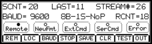
Figure 10 Remote Control Submenu
The first line of the LCD shows three parameters that can assist the operator in checking remote RS232 serial
operations.
The first item is the SCNT=20, which is the count of serial remote commands that have been received by the MXi. The
value is a hexadecimal count (20 in our example which is 32 decimal) which will increment upon the arrival of a new
serial remote command. The source of the serial command is via the RS232 serial program. When the count hits $FF
the next command will cause it to roll over to a value of $00.
The second item is the LAST=11, which is the actual hexadecimal value assigned to the remote command that was
just received. The operator can use this information to determine what command has been received and determine
whether the action has been indeed taken.
The third item is the STREAM#=26, which is the actual hexadecimal count of the number of serial streams sent out the
RS232 port. The MXi sends a complete serial stream out the RS232 port about once per second and so this count
should increment around once per second. When the count hits $FF, the next command causes it to roll over to a
value of $00. The operator can use this information to verify that the MXi is indeed sending serial data and can
compare the stream number to that received by the remote computer program.
The second line of the LCD shows three parameters that can assist the operator in checking remote operations and
setups.
The first item is the BAUD=9600, which is the serial baud (bits per second) that is currently being used by the MXi to send
serial data out the RS232 port. The value can be set by the operator and can range from 300 to 38,400 bits per second.
The operator would need to set this baud to match the remote PC and modem setup.
The second item is the 8B-1S-NoP, which is the serial format that is being used for the RS232 stream. This stands for 8
data bits, 1 stop bit and no parity. The operator should set his remote computer to match this serial format setting. The
only parameter that can be changed by the user is the number of stop bits. The user can set either 1 or 2 stop bits.
The third item is the RCNT=10, which is the actual hexadecimal count of the last RS232 or external remote commands
that were received. Note that this is a count of commands received via the RS232 serial port or commands from the
individual J5 remote commands. The operator can uses this information along with the SCNT value from line #1 of the
LCD to determine the source of the remote command. If the RCNT increments but the SCNT does not, then the recent
remote command came from J5. If both the SCNT and the RCNT increment, then the recent remote command came
from the RS232 stream.
The third line of the display has a number of status lights with a legend describing the particular status underneath and all
enclosed in a dashed line box. When the light is fully darkened, it indicates that this particular status is true or active.
When the light is hollow, it indicates that this particular status is false and inactive. Each status is detailed as follows.
MXI1503-2004 CONTROL UNIT
PUB13-09 Rev 1 20
2.7.1 Remote
The operator has the option of allowing remote commands or disabling them. When performing some sort of
maintenance or local setups, the operator will usually disable any remote commands until the work on the transmitter is
completed. If the operator has elected to disable the remote mode, be careful not to forget to put the transmitter back
in Remote mode or else the remote controls will not be operational. The menu button options on the bottom line of the
LCD provide the controls to Enable/Disable remote controls.
Lit when Remote commands are enabled.
Not lit when Remote commands are disabled.
2.7.2 NewFmt
New Serial Format has been selected but not taken.
The operator has the option of changing the baud rate or number of stop bits for the serial RS232 communications. If a
change has been selected, it is not implemented until the operator presses the SAVE menu button on the LCD. This
status tells the operator that the recently selected format is different from the one currently being used for the serial
stream.
Lit when there is a pending change in the serial format.
Not lit when there is no serial format change or the selected format is the same as the current one.
2.7.3 ExtCmd
External Serial Command Received
The external remote control system can assert a command onto the individual remote inputs at J5. The MXi will set the
ExtCmd status if a valid command has been received. This is useful in detecting remote commands issued to the MXi
from the remote control system. This bit can be cleared by the CLR menu button on the LCD.
Lit when an external serial command from J6 has been received.
Not lit when no external serial command from J6 has been received since the last clear.
2.7.4 SerCmd
RS232 Serial Command Received
The external computer will send a four-byte serial stream of a specific format to ask for a certain action to be taken.
The MXi will set the SerCmd status if a valid command has been received. This is useful in detecting serial
transmissions between the external computer and the MXi. This bit can be cleared by the CLR menu button on the
LCD.
Lit when a RS232 serial command from the computer has been received.
Not lit when no RS232 serial command from the computer has been received since the last clear.
MXI1503-2004 CONTROL UNIT
PUB13-09 Rev 1 21
2.7.5 Error
Serial Input Stream Error
The external computer will send a four-byte serial stream of a specific format to ask for a certain action to be taken.
The MXi monitors the format of this four-byte serial stream and sets the Error status if the stream has the wrong
format. This is useful in determining if there is a serial transmission problem between the external computer and the
MXi. This bit can be cleared by the CLR menu button on the LCD.
Lit when an error was detected in the RS232 command stream since the last clear.
Not lit when no error has been detected in the RS232 command stream since the last clear.
2.7.6 SubMenu Select Buttons
The bottom line represents the menu selection buttons with a possible option of eight different selections. The operator
just needs to press the touchpad (lightly) either on or just above the desired menu select button.
The first two buttons from the left control the Remote mode of the MXi transmitter. The operator has the option of
allowing remote commands or disabling them. When performing some sort of maintenance or local setups, the
operator will usually disable any remote commands until the work on the transmitter is completed. If the operator has
elected to disable the Remote mode, be careful not to forget to put the transmitter back in Remote mode or else the
remote controls will not be operational. The first menu button Remote enables the remote commands and the second
button Local disables the remote commands. The status light labeled Remote on the third line of the LCD indicates the
current state of the transmitter.
Remote = Enable Remote Operation for the MXi
Local = Disable Remote Operations for the MXi
The BAUD button on the bottom of the LCD touchpad causes the baud to increment from the current displayed baud
up to the next higher one. At the same time, the NewFmt light on the third line lights to indicate that a new serial format
(Baud or Stop bits or both) is pending but not taken. Successive pushes of the BAUD button cause the baud to
increment until it reaches the maximum of 19,200 baud, after which it will roll back to 300 baud, which is the lowest
rate. Note that when setting the baud, if the NewFmt light is on, the rate displayed on the screen is the new baud that is
not yet programmed. The MXi will still operate at the original Baud rate until the new one is saved.
If the user presses the STOP menu button, then the number of stop bits in the serial format will toggle between 1 and
2. The new desired number of stop bits will be displayed in the second line of the LCD within the 8B-1S-NoP section
where the stop bits will be either 1S or 2S in this string. At the same time, the NewFmt light on the third line will light to
indicate that a new serial format (Baud or Stop bits or both) is pending but not taken.
Once the operator is satisfied with the new baud and Stop bits, pressing the SAVE button causes the MXi to implement
the new serial format. Pressing the CLR button abandons all selections and revert to the previous baud and Stop bits
without any action being taken.
The CLR button will also clear the SCNT value on the first line, the RCNT value on the second line along with the
ExtCmd, SerCmd and Error status lights on the third line.
BAUD = Increment the target baud rate for RS232 communications
STOP = Toggle between one or two Stop bits
SAVE = Save the new Serial format values (Baud & Stop)
CLR = Restore previous Serial format values (abort changes) and clear Remote command counters
TEST = Unimplemented, this button has no function
OUT = Returns LCD to the main LCD Screen.
MXI1503-2004 CONTROL UNIT
PUB13-09 Rev 1 22
2.8 GENERAL SCREEN
The General submenu is entered by pressing the GEN submenu button on the main LCD screen.
This submenu displays all the configuration and setup information of the particular model of MXi transmitter. The first
line displays the transmitter type, the second line displays the software code and revision, the third line displays the
LARCAN ID number that is used in the factory to determine options, date the boards were made and other information.
This information is not really important for day to day operations but can be useful when dealing with LARCAN service
in verifying the transmitter configuration.
The bottom line represents the menu selection buttons with a possible option of eight different selections. The operator
just needs to press the touchpad (lightly) either on or just above the desired menu select button.
The first two buttons from the left control allow access to two level 2 submenus. One is for setting up the real time
clock and the second is for internet setup. Note that the internet is a purchased option and may not be functional on a
given transmitter configuration.
RTC = Go to the Real Time Clock Submenu
INET = Go to the Internet Setup Submenu
OUT = Returns LCD to the main LCD Screen.
2.8.1 Real Time Clock Submenu
The Real Time Clock submenu is entered by pressing the RTC submenu button on the SYS submenu LCD screen.
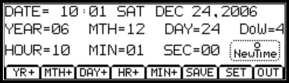
Figure 11 Real Time Clock Submenu Screen
This submenu displays the current time and date in the real time clock chip and allows the operator to reset the time
and date.
The first line displays the current time and date as known by the real time clock. The time/date will be used for any
logs that the system records.
The second and third lines have target date and time values used by the operator when resetting the current time or
date. The operator can use the control buttons on line four of this LCD to increment the various time/date elements.
The DoW (Day of Week) is not changed by the operator but the system calculates this value from the other time &
date parameters.
The status LED ‘NewTime’ on the third line of the LCD will be lit when there is a new value set by the operator in any of
the time or data values on lines two or three.
2.8.2 SubMenu Select Buttons
The bottom line represents the menu selection buttons with a possible option of eight different selections. The operator
just needs to press the touchpad (lightly) either on or just above the desired menu select button.
The first five buttons from the left allow the operator to set a new time or date for the system. The user can set the
Year, Month and Day of the date portion. The system will automatically adjust the DoW (day of week) depending on

MXI1503-2004 CONTROL UNIT
PUB13-09 Rev 1 23
the date set. The operator can set the Hour and Minute of the time but seconds will be set to zero so if a person
wants to calibrate to the second then if the current time is 11:40.22 then set the time for 11:41.00 and press SAVE
when the reference time hits 11:41.00
Once a value is changed, the ‘NewTime’ status LED will be lit showing a new time/date has been entered. This LED
will extinguish when the operator either saves the new time, resets the values or exits this submenu.
If a person makes an error setting the values (like incrementing the year too many times), the SET button will reset the
default values again.
YR+ = Increment the year. The maximum value is 49 after which it wraps back to 06.
MTH+ = Increment the month. After a value of 12, the value will wrap back to 01
DAY+ = Increment the day. Maximum value is the number of days in current month (accounts leap years)
HR+ = Increment the hour. This is a 24 hour format and the value can range from 00 to 23
MIN+ = Increment the minute. This can range from 00 to 59, after a value of 59 it wraps back to zero
SAV = Save the new time values into the Real Time Clock
SET = Reset the time and date values back to their defaults.
OUT = Returns LCD to the System Submenu LCD Screen.
2.9 INTERNET SETUP SCREEN
The Internet Setup submenu is entered by pressing the INET submenu button on the System submenu screen.
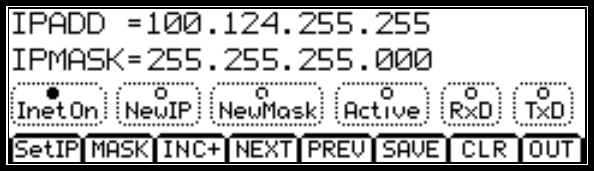
Figure 12 Internet SetUp Submenu Screen
This submenu displays all the configuration and setup information for the internet option. Note that this is a purchased
option that must be specified at the time of order. This function will not work unless specifically enabled and
configured at the factory.
The internet functionality is beyond the scope of this manual and so only a brief description will be given here. When
the option is purchased a separate publication will be supplied.
The first line shows the current IP address that the MXi will respond to. This value must be obtained from the
customers IT personnel or network provider. LARCAN cannot provide this since it is customer network dependant.
The second line show the IP Mask value that restricts the range of IP addresses that the MXi unit will respond to. This
can be used to restrict access to a certain IP address or groups of IP addresses. Again, consult your local IT person
for this value.
The third line has a number of status LEDs that indicate the various possible conditions of the internet operation.
These are defined as follows
Inet On = Internet interface is active and will respond to external requests [factory setting]
NewIP = Operator has changed (but not yet saved) and new IP address
NewMask = Operator has changed (but not yet saved) and new IP Mask address
MXI1503-2004 CONTROL UNIT
PUB13-09 Rev 1 24
Active = The internet is currently receiving or transmitting data
RxD = Data is being received
TxD = Data is being transmitted
2.9.1 SubMenu Select Buttons
The bottom line represents the menu selection buttons with a possible option of eight different selections. The operator
just needs to press the touchpad (lightly) either on or just above the desired menu select button.
The first seven buttons are involved in setting the Internet address and Mask Addresses. Each of these addresses are
divided into four sections of three digits each. The operator can increment each of these three digit numbers separately
and then move on to the next set if required. Once completed the new values can be saved.
Figure 13 Internet SetUp Submenu Screen
SetIP = Set a new IP address, Moves cursor to the first 3 digit number (100 in this case)
Mask = Set a new IP Mask address, Moves cursor to the first 3 digit number (255 in this case)
INC+ = Increment the current IP or IP Mask number, If current number is 100 then go to 101
NEXT = Move to the next 3 digit IP number, If at the last digits then nothing is done
PREV= Move to the previous 3 digit IP number, If at the first digits then nothing is done
SAVE = Save the new IP or IP MASK address
CLR = Restore the default IP addresses and discard any changes made
OUT = Returns LCD to the System Submenu LCD Screen.
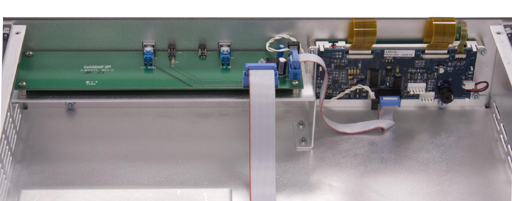
MXI1503-2004 CONTROL UNIT
PUB13-09 Rev 1 25
3 FRONT PANEL INTERFACE BOARD
The main controller board connects to a separate front panel interface board via a 16 wire ribbon cable. Connector
J15 on the main controller board is wired to connector J1 of the front panel interface board via this 16 wire ribbon
cable. The front panel interface board is located at the front of the power supply chassis whereas the controller board
is located in the rear of the power supply chassis.
Figure 14 Front Panel Board
The MXi has a very simple set of front panel controls and indications that consists of three primary sections, the LCD
interface, the ERROR status/reset and the transmitter ON/OFF status/control.
The schematic and assembly for the Front Panel Interface board (21B2537G1 Rev 0) are given in Figure 16.
The VSWR trip status is displayed via a front panel (red) LED, which will be illuminated whenever a VSWR Trip
condition has occurred.
The ON/OFF pushbutton is used to turn the transmitter ON or OFF for local or remote control. This button is an
alternate action device that, once pressed, remains in the ON state (pressed in). If the operator presses the button a
second time, it releases into the OFF state. The function of this button can be set up to directly control the ON/OFF
relay K2 and bypass the CPU control by installing jumper E4. Jumper E4 would only be installed for testing or
emergency operations. Normal operation has jumper E4 removed such that the CPU reads the state of the ON/OFF
button and will in turn activate the relay E4.
The LCD provides a graphical user interface (GUI) that allows the operator to monitor and control the operation of the
Mxi transmitter
3.1.1 LCD Interface
The MXi provides a graphical user interface via a front panel LCD display with integrated touchpad. This touchpad
communicates to the main controller through a standard 9600 baud RS232 interface. This is a simple three wire
interface (TxData, RxData & Ground) with no handshaking hardware lines. The front panel interface board connects to
the LCD with a 10 wire ribbon cable J3, that is attached directly to a 10 pin connector on the LCD display. The
sequence of signals on this 10 pin cable follows a standard 9 pin D-shell layout where the last 10th pin is not used.
The LCD also requires a +5V power that is provided through a 2 pin connector (+5V and ground) J2, on the front panel
interface board. The front panel interface board receives a +12V input from the main controller board and then
regulates this down to +5V for the LCD display. The main controller board does indeed have its own +5V power but it
was decided that running a +5V supply through the 16 pin ribbon cable on top of the two high current power supplies
might result in noise pickup. It was for this reason that the +12V is sent over the 16 wire cable and then regulated near
the LCD itself on the front panel interface board.
MXI1503-2004 CONTROL UNIT
PUB13-09 Rev 1 26
3.1.2 Error LED and Reset Control
The front panel Error LED (DS1) is located on the front panel interface board and indicates if there is a current error
condition on the amplifier. Typical Errors would be VSWR Trips, Interlocks open, Power supply overcurrent, etc. The
microprocessor software code on the main controller board provides the signal to drive this LED and will illuminate it
whenever a current Error Condition exists.
The front panel interface board has a momentary switch S1 that is used to reset the current Error condition. This
switch is a two pole device where one pole directly resets the VSWR Relay on the main controller board and the
second pole is fed into the microprocessor to reset any error conditions that the software has detected.
3.1.3 Front Panel On/Off Control and Status
The front panel ON LED (DS2) is located on the front panel interface board and indicates if the ON relay on the main
controller is currently activated in the ON state. This LED will illuminate green when the relay is active.
This switch is an alternate action device that, once pressed, remains in the ON state (pressed in). If the operator
presses the button a second time, it releases into the OFF state. The function of this button can be set up for a variety
of operations depending on how the circuit board jumpers are configured.
Allows the MXi CPU to directly control all local and remote ON/OFF commands. The front panel ON/OFF command
will only operate when the system is in local and the remote commands will only operate when the system is in remote.
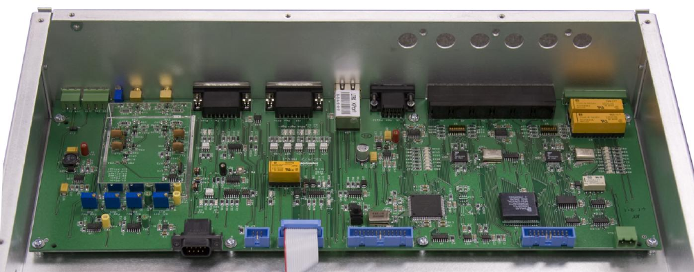
MXI1503-2004 CONTROL UNIT
PUB13-09 Rev 1 27
4 MAIN CONTROL BOARD
This section describes the 31C1972 CPU Board (referred to hereafter as the Main CPU Board).
This Printed Circuit Board (PC Board) is the communications center of the transmitter where all serial communications
throughout the transmitter system are routed. This PC Board also handles the basic remote control functions of the
transmitter system.
The CPU Board is located in the rear of the control chassis with the interface connectors protruding through the rear
panel.
Figure 15 CPU Board Shown Mounted in the Control Chassis
The CPU Board communicates serially each amplifier and the Front Panel Interface board. The Information that is
sent to the Front Panel Interface board gets pass through to the Touch Screen. The board also has a 9-Pin D RS232
connector and an Ethernet RJ-45 connector that are allocated as remote ports.
The CPU Board incorporates five remote inputs, three telemetry outputs and six status outputs. These are used for
remote interface to a customer-specific remote control system. The remote signals generated by the CPU Board
comprise the basic remote functions that would be required.
The following sections detail the function and implementation of the circuitry on the CPU Board.
4.1 GENERAL LAYOUT AND SUBSYSTEMS
The CPU Board can be divided into a number of logical sections that make it easier for the operator to understand
which functions the board is performing. These systems are the Serial Communication, RF Metering, On/OFF Relay
Control, Remote Controls and Status, Information Storage, and Rear Panel Interface.
4.1.1 Serial Communications
The CPU Board has three asynchronous RS232 serial ports called SCIs however the CPU board requires seven serial
communication lines to communication with up to four Amplifiers, the Touch Screen, the Remote RS232 port and the
Ethernet Port. To get the required number of serial ports the micros extended addressing lines are used to
communicate with two UARTs. This provides a total of 8 serial ports that can be accessed and read by the micro
processor.

MXI1503-2004 CONTROL UNIT
PUB13-09 Rev 1 28
4.1.2 RF Metering
The MXi receives two RF inputs for the combined forward (J12) and reflected (J13) powers. RF Power levels are
sampled by a directional coupler located at the output of the final combiner and the resulting RF samples are detected
and appropriately processed to provide DC outputs corresponding to the amplitude of the desired parameter of the
input signal. These DC outputs contribute to the AGC/VSWR supervision of the transmitter and are also processed in
analog to digital conversion circuits on the main controller board to provide digital metering.
The RF Detector can have different group assemblies to support the NTSC system, the PAL system and Digital
transmission. NTSC and PAL application differ only in their color subcarrier frequency, consequently in a few
component values. All group assemblies use the same PC Board and have many jumpers used to change circuit
sensitivity, introduce/remove traps for color subcarrier and/or aural intercarrier and change envelope detector
characteristics for digital and analog applications.
The schematic included in this publication shows the circuitry for NTSC and Digital transmissions. For PAL systems a
separate schematic would be included that is currently not in this publication.
All jumpers are set in the factory and should not be modified in the field unless under direction from LARCAN
personnel.
Required signal levels are as follows:
FWD (overall forward sample) metering requires 20dBm sync peak signal for full scale (100% rated power).
RFL (overall reflected sample) metering requires 10dBm sync peak signal for full scale (10% rated power).
The forward RF detector can be configured for a number of different signal types as the following table shows.
DESCRIPTION
E7
E8
E10
Default Analog NTSC: +20dBm, Visual, Color Burst and Aur Carrier Trapped
LO
Installed
Installed
Default Analog NTSC: +20dBm, Visual, Color Burst and Aur Carrier Trapped
LO
Installed
Installed
Default Analog NTSC: +17dBm, Visual, Color Burst and Aur Carrier Trapped
HI
Installed
Installed
Default Analog NTSC: +17dBm, Visual, Color Burst and Aur Carrier Trapped
HI
Installed
Installed
Special Analog NTSC: +20dBm, Visual+Aural, Color Burst Trapped
LO
Absent
Installed
Special Analog NTSC: +20dBm, Visual+Aural, Color Burst Trapped
LO
Absent
Installed
Special Analog NTSC: +17dBm, Visual+Aural, Color Burst Trapped
HI
Absent
Installed
Special Analog NTSC: +17dBm, Visual+Aural, Color Burst Trapped
HI
Absent
Installed
Digital Signal: +20dBm, Ave Detector, No Traps (also Special Analog NTSC)
LO
Absent
Absent
Digital Signal: +20dBm, Ave Detector, No Traps (also Special Analog NTSC)
LO
Absent
Absent
Digital Signal: +17dBm, Ave Detector, No Traps (also Special Analog NTSC)
HI
Absent
Absent
Digital Signal: +17dBm, Ave Detector, No Traps (also Special Analog NTSC)
HI
Absent
Absent
Not Used: Visual + Color Burst and Aur Carrier Trapped
X
Installed
Absent
Two almost identical detector circuits reside on a single board for visual forward and reflected metering. Detection
sensitivity of the circuit dedicated to reflected visual power is approximately 10dB greater than for the visual forward RF
detector circuit. The reflected port reading is combined visual and aural power. The jumper configuration for the
reflected power follows that of the above table with E6 replacing E7; E9 replacing E8; and E11 replacing E10.
4.1.2.1. VSWR Protection Circuitry
DC samples of the Forward and Reflected power reading generated by on the RF detectors are used compared to
generate a VSWR Trip and Lockout.
MXI1503-2004 CONTROL UNIT
PUB13-09 Rev 1 29
When the reflected level exceeds –10dB, set coil of relay K2 is energized, causing a VSWR trip to occur. Relay K2 is a
two-coil latched relay where energizing the set coil causes the contacts of K2 to move into the set position and remain
there even after the coil is de-energized. Once a VSWR trip has occurred, the relay K2 will remain in the set position until
a signal is sent to the other reset coil that moves the contacts back into the original clear position.
The relay K2 can be reset from one of two sources.
The microprocessor can reset the relay after receiving either a remote request to issue a reset or a command from the
front panel touchscreen. The relay can also be reset by pressing the front panel Reset button.
The VSWR relay has two poles, one for the transmitter interlock and the second for status. The interlock pole is part of the
arming interlock chain of the ON/OFF relay K4. If the K2 contact is opened (i.e., there was a VSWR trip), the arming
voltage is removed from ON/OFF relay K4 and the transmitter shuts down. Note that jumper E12 is provided to override
the VSWR relay trip contacts. This jumper is only for setup purposes and should never be left installed in normal
operations.
Note: Leaving the jumper E12 installed will defeat all the VSWR protection and could result in damage to the RF amplifier
if a high reflected power condition occurs.
The second pole of K2 lights status LED DS4 when the relay has tripped under VSWR condition. The other side of this
pole is fed into the CPU, which uses this to determine if K2 is tripped or not.
4.2 ON/OFF RELAY K4
The ON/OFF relay K4 is a four-pole, single-side stable relay that requires a constant voltage applied to its coil to
maintain contact closure. The contacts of this relay are connected to each Amplifier’s External Interlock which when
closed provide the control signals to activate each amplifiers +50V power supply and the cooling fans.
There are two elements that determine if power is applied to the coil of K4. One is the +12V arming voltage on the
positive side of the coil that comes from the interlock chain. Two interlocks are placed in series with this coil such that
both must be closed in order for K4 to receive its +12V arming voltage. The two interlocks are External #1 and VSWR
Trip. If either of these interlocks is open, then the relay will not be energized and transmitter amplifiers will be shut
down.
The second element that determines if power is applied to the coil of K4 is the control signal on the negative side of the
coil. This control signal can come from two sources.
The microprocessor can activate the coil if it were to receive an ON command via remote control or the coil could be
activated by pressing the front panel ON button
When K4 is energized, all four poles of the relay will close and cause the transmitter to generate RF power.
4.2.1 Remote I/O
The CPU board implements eight optically isolated inputs, ten optically isolated outputs and five analog telemetry
outputs which are typically used for transmitter remote controls. The eight remote control inputs are active low inputs
requiring current sink to ground and have an associated indicator LED located on the front edge of the CPU Board.
The ten outputs are used by the CPU Board as remote status indicators. Eight of these are transmitter status while the
other two are modulator switch status. These status outputs are open collector sinking current to ground and do not
have any pull-ups. The eight status outputs related to the transmitter have associated indicator LEDs located on the
front edge of the CPU Board.
4.2.2 Information Storage
The CPU uses an external 8K Nonvolatile RAM (NovRAM) for storing important transmitter parameters with the
transmitter logs. This unit has a battery backup so the information is not lost during power loss or if the
microprocessor is reprogrammed.
4.2.3 Remote Controls and Status
The CPU Board incorporates five remote inputs, three telemetry outputs and six status outputs. These are used for
remote interface to a customer-specific remote control system. The remote signals generated by the CPU Board

MXI1503-2004 CONTROL UNIT
PUB13-09 Rev 1 30
comprise the basic remote functions that would be required. The CPU board also provides a RS232 interface and a
RJ45 connection, either of which could be used with the In-SiNC program.
4.2.3.1. Combined Remote Controls
The Transmitter MODE must be in REMOTE for any of these remote controls to be operational. The transmitter is
placed in the REMOTE mode via the touchscreen. The main LCD screen has a status light to show if the REMOTE
MODE is active.
The MXi provides 5 remote control inputs that effectively replicates its own front panel and LCD mode control buttons.
These five controls consist of ‘Tx ON’, ‘Tx OFF’, ‘Reset’, ‘Agc Raise’ and ‘Agc Lower’.
The combined remote controls are active low, opto-isolated inputs which require a GROUND for assertion and the
activator to be able to sink 15mA or more for at least 200 milliseconds to accomplish reliable keying. Each of these is
current-limited by an individual resistor.
TX D-Connector (J10)
Designation
Description
Pin 3
RC_TX_On
Turns Transmitter ON
Pin 4
RC_TX_Off
Turns Transmitter OFF
Pin 5
RC_VRST
Resets VSWR Trips
Pin 6
RC_AGC+
AGC (Power) Raise
Pin 7
RC_AGC-
AGC (Power) Lower
Pin 15
Ground
Ground Reference
4.2.3.2. Combined Remote Status Outputs
These are current sinking open collector outputs, out of quad pack MPQ2222 (2N2222A) NPN transistors driven by
opto-isolator devices. The available output sink current is dependent on the gain of the NPN and the opto-isolator
transfer ratio. Generally, one can expect at least 100mA of sinking current for each output listed here. Because these
are open collector, they can be used in special applications, such as on-site warning signal activation if desired, but
they are limited in external circuit voltage to maximum 60VDC. Each status (in parentheses) indicates what it means
when in its active low condition.
The MXi provides six remote status outputs that represent the current operating state of the transmitter.
TX D-Connector (J10)
Designation
Description
Pin 8
RS TXOn
Tx is turned ON
Pin 9
RS_Remote
Tx is in Remote Mode
Pin 10
RS VTrip
VSWR Trip Occurred
Pin 11
RS_VLock
Tx is OFF due to VSWR
Pin 12
RS_INTK
EXT 1 is closed
Pin 13
RS_Err
Tx has an error
Pin 15
Ground
Ground Reference
4.2.3.3. Combined Telemetry Outputs
These are buffered OpAmp outputs, out of quad pack LM324 operational amplifiers. The available output voltage is
limited to the range of 0 – 5VDC. The OpAmp can reliably source around 5mA of current and so a relatively high

MXI1503-2004 CONTROL UNIT
PUB13-09 Rev 1 31
impedance input of at least 2K ohms should be used. Each telemetry has a description to indicate what parameter it is
measuring.
The MXi provides three remote telemetry outputs that represent the current operating levels of the transmitter.
TX D-Connector
Designation
Description
Pin 1
FWD PWR
Forward RF power level
Pin 2
RFL PWR
Reflected RF power level
Pin 14
AGC SET
AGC Reference Level
Pin 15
Ground
Ground Reference
4.3 INTERCONNECTIONS FROM THE CPU BOARD
The following provides a brief description of the basic function of each connector on this board.
J1 – Serial Interface for Amplifier 1
J2 – Serial Interface for Amplifier 2
J3 – Serial Interface for Amplifier 3
J4 – Serial Interface for Amplifier 4 (for an MXi2004)
J5 – Not Used
J6 – Not Used
J7 – Amplifier Interlocks
J8 – Remote RS232 Interface
J9 – Remote RJ45 Interface
J10 – Parallel Remote Control, Status and Telemetry
J11 – Not Used
J12 – Forward Power
J13 – Reflected Power
J14 – Not Used
J15 – Front Panel Board Interface
J16 – BDM Connector (Only used for programming the microprocessor)
J17 – Test Connector (Only used for in factory testing)
J18 – Factory Use Only
J19 – Factory Use Only
J20 – External 1 Interlock
J21 – 12V DC input
A summary of all the signals on these connectors is given in sheet 5 of schematic 31C1972.
MXI1503-2004 CONTROL UNIT
PUB13-09 Rev 1 32
5 +12 V DC CONTROL POWER SUPPLY
Mounted in the control chassis between the Main Control board and the Front Panel Interface board is the +12DC
Control Power Supply. This provides the +12V DC for the main control chassis as well as each amplifier. The power
supply is connected to a rear panel terminal block and then wired to each amplifier. The +12VDC is turned on as soon
as AC it applied.
MXI1503-2004 CONTROL UNIT
PUB13-09 Rev 1 33
6 TROUBLE SHOOTING
There are some steps the user can take in the unlikely event that a problem occurs. The following sections list some
possible problems and the steps to rectify them.
6.1 CHECK THE CONTROL POWER SUPPLY VOLTAGES
No matter what the problem, it is a good idea to verify that the control power supply voltages are within tolerance. You
can do this measuring the voltages found on the input power connector J21 located on the main control board. Verify
that the +12V is above 10V but not greater than 14V
6.2 THE CPU BOARD IS NOT COMMUNICATING WITH FRONT PANEL BOARD OR TOUCH SCREEN
If this is the only communication problem, verify that the programming cable at J15 in the main control board 31C1972
is installed.
6.3 TOTAL LOSS OF CPU FUNCTIONS
In the case that the CPU Board is not communicating with any other board and does not respond to remote
commands, then it might be hung in a software loop. This can occur when new hardware or the touch screen has been
installed while DC voltage was still applied and the CPU Board was not in reset mode.
Simply push the reset switch S1. This will reset the CPU and restart the program.
6.4 THE REAL-TIME CLOCK DOES NOT RETAIN ITS TIME AFTER POWER OUTAGES
The real-time clock is implemented in the NovRam IC and is powered by a battery unit. A new battery unit should be
ordered from LARCAN and replace the old unit. This battery is designed to last about 15 to 20 years and so should not
exhibit any issues until near the end of the transmitter life cycle.
6.5 SERVICE DEPARTMENT CONTACT INFORMATION
The CPU Board is comprised of mostly surface mount components, thus any other problems are most likely beyond
the scope of service in the field and should be referred to LARCAN Service.
LARCAN INC. Phone: (905) 564-9222
228 Ambassador Drive, Fax: (905) 564-9244
Mississauga, Ontario, Canada L5T 2J2 e-mail: techservices@larcan.com
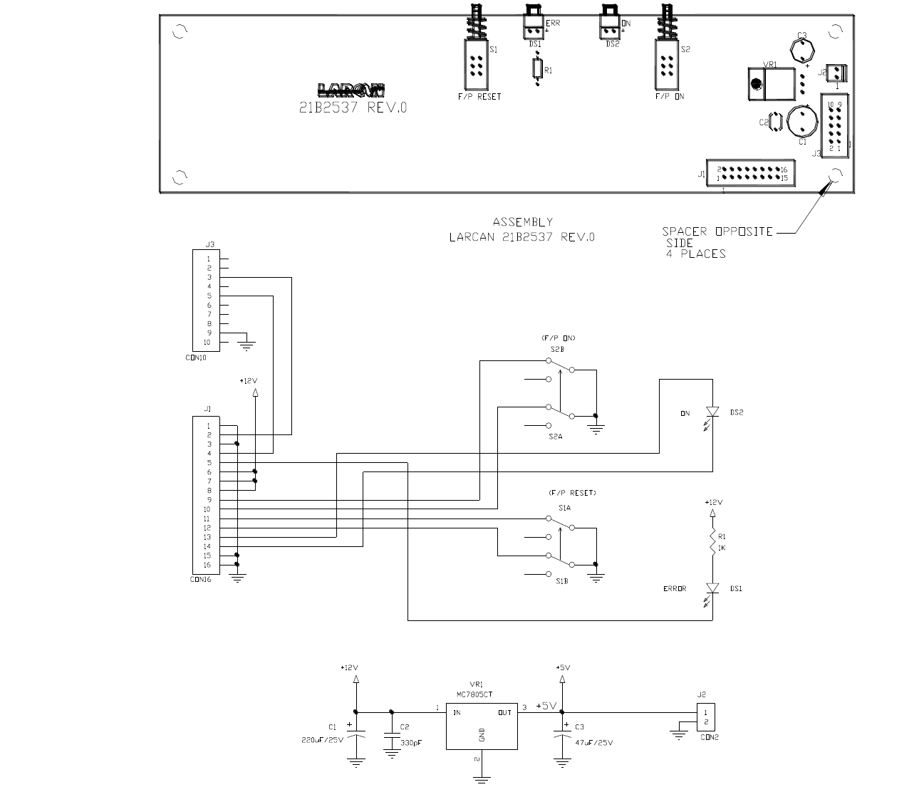
MXI1503-2004 CONTROL UNIT
PUB13-09 Rev 1 35
Figure 16 MXi Front Panel Interface Board Assembly 21B2537A1 and Schematic 21B2537S1
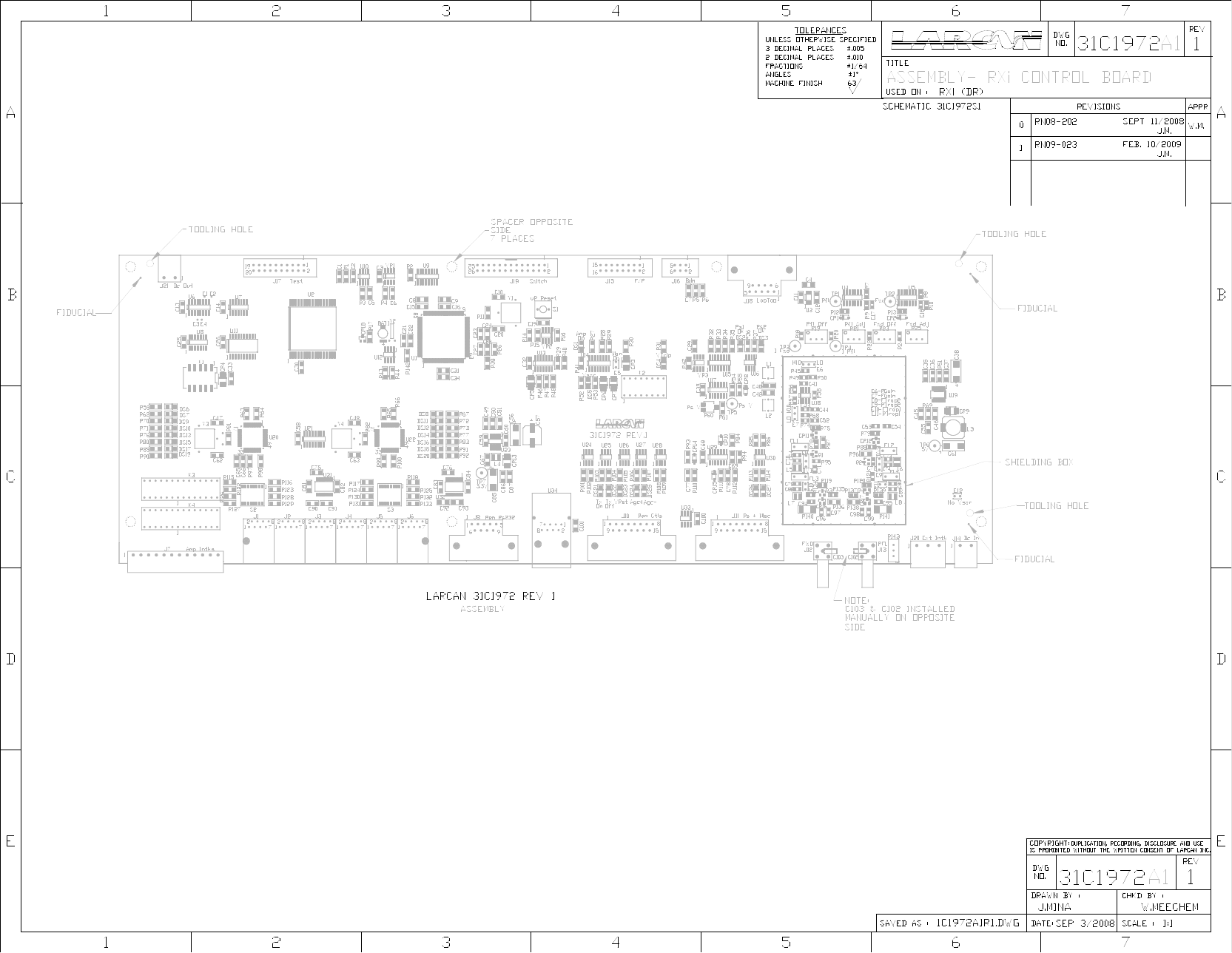
MXI1503-2004 CONTROL UNIT
PUB13-09 Rev 1 36
Figure 17 Main Control Board Assembly – 31C1996A1
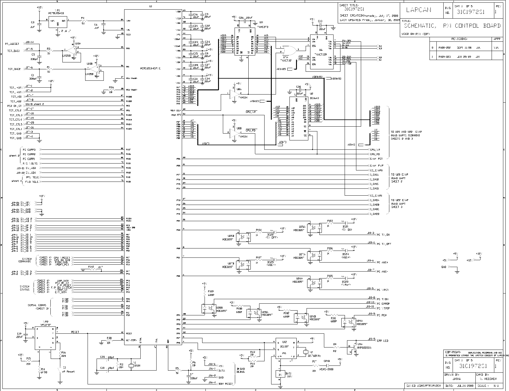
MXI1503-2004 CONTROL UNIT
PUB13-09 Rev 1 37
Figure 18 Main Control Board Schematic Sheet 1
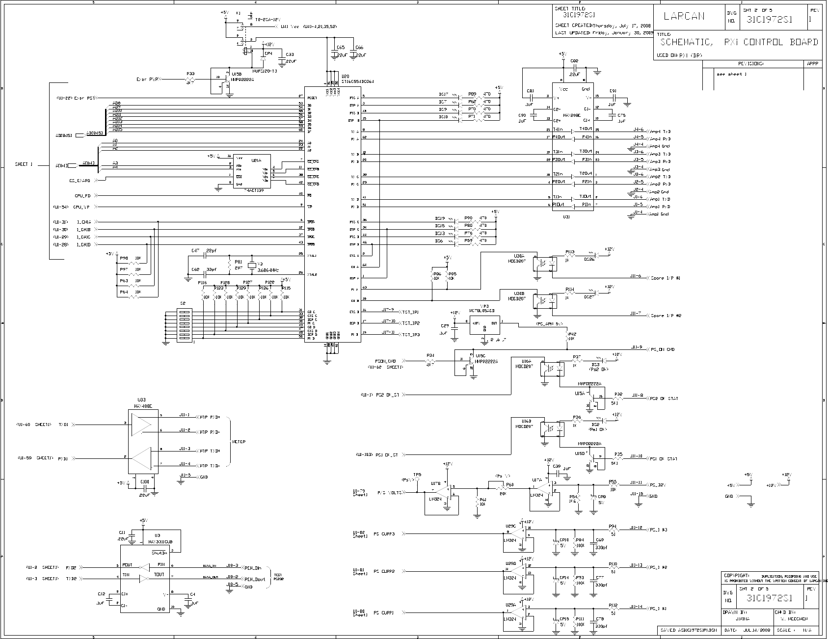
MXI1503-2004 CONTROL UNIT
PUB13-09 Rev 1 38
Figure 19 Main Control Board Schematic Sheet 2
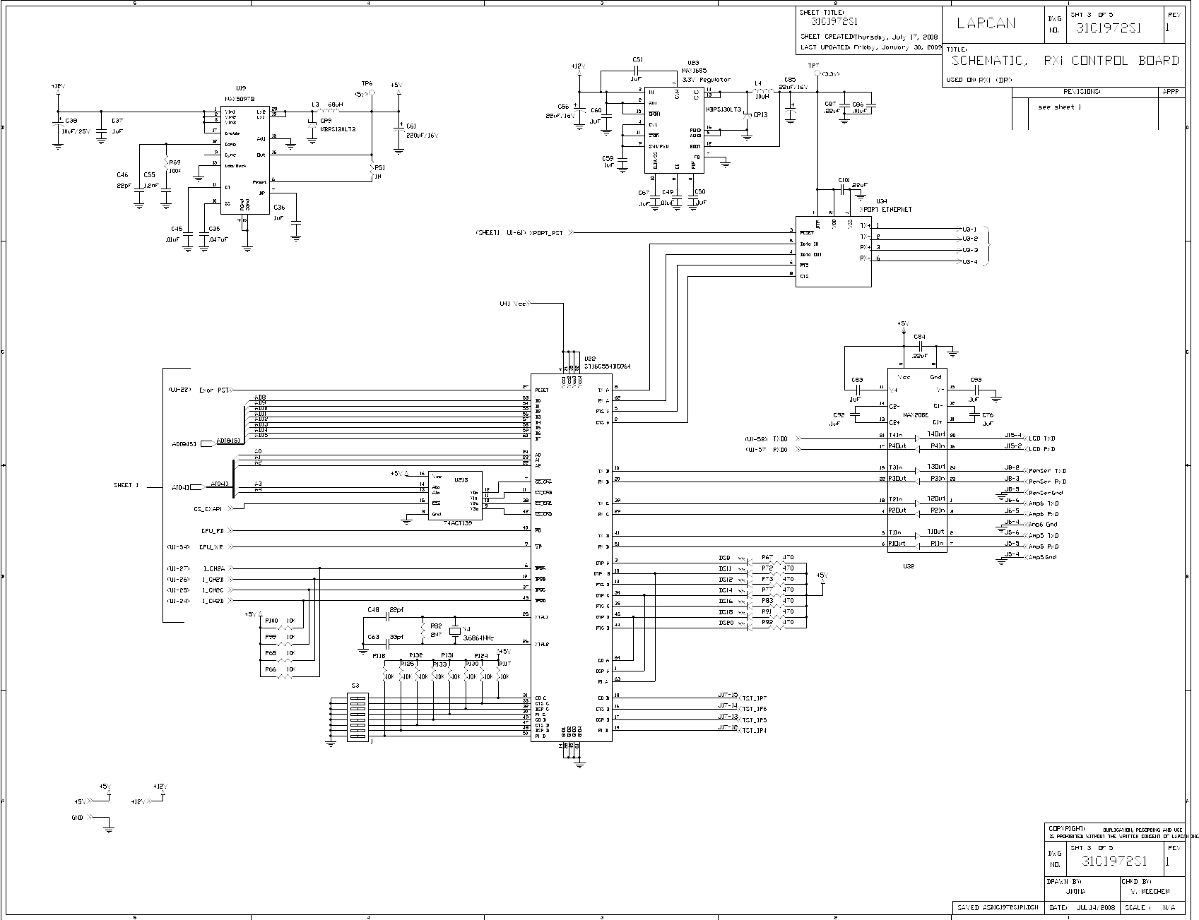
MXI1503-2004 CONTROL UNIT
PUB13-09 Rev 1 39
Figure 20 Main Control Board Schematic Sheet 3
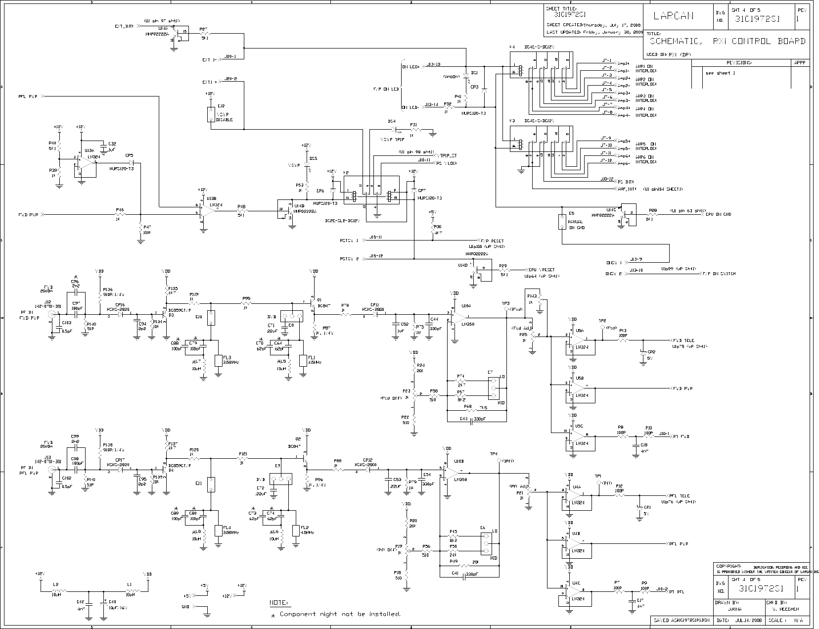
MXI1503-2004 CONTROL UNIT
PUB13-09 Rev 1 40
Figure 21 Main Control Board Schematic Sheet 4
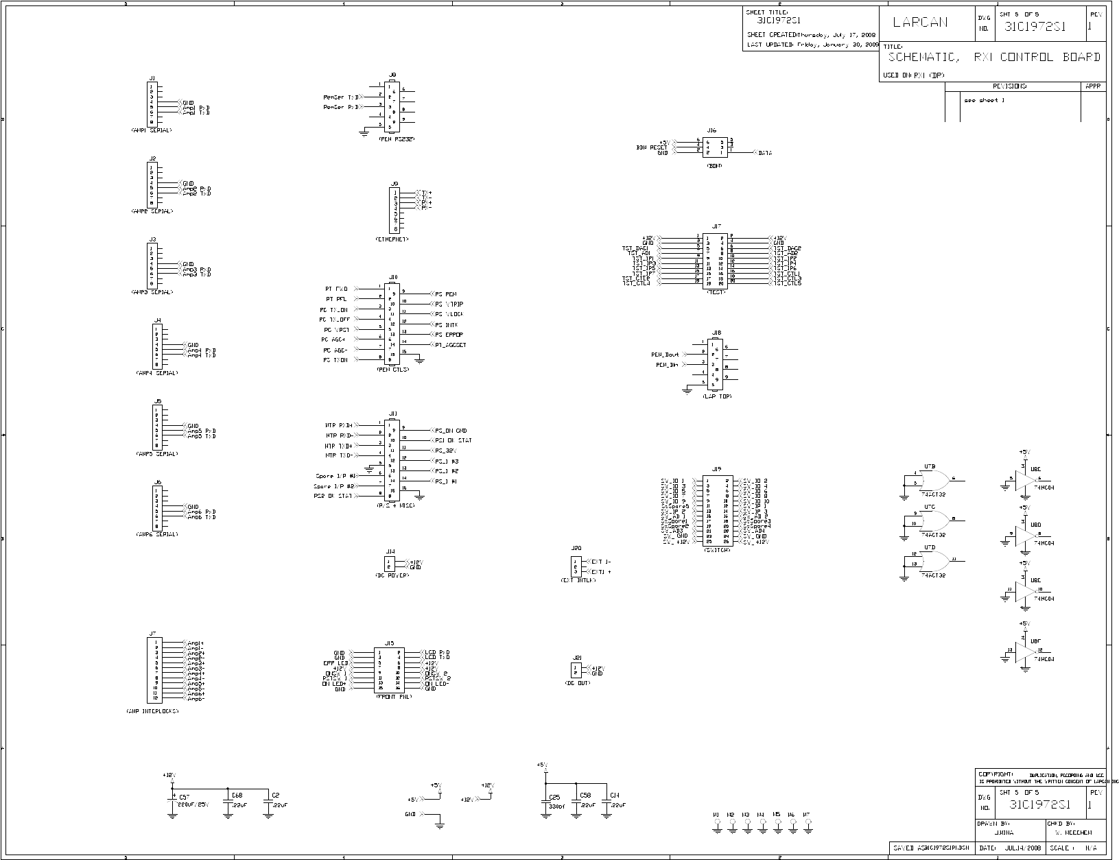
MXI1503-2004 CONTROL UNIT
PUB13-09 Rev 1 41
Figure 22 Main Control Board Schematic Sheet 5

MXI1503-2004 CONTROL UNIT
PUB13-09 Rev 1
NOTES