Larcan T2500U 2500 Watt UHF Transmitter User Manual RTU5000T
Larcan Inc 2500 Watt UHF Transmitter RTU5000T
Larcan >
Contents
- 1. user manual for tx part1
- 2. user manual for tx part2
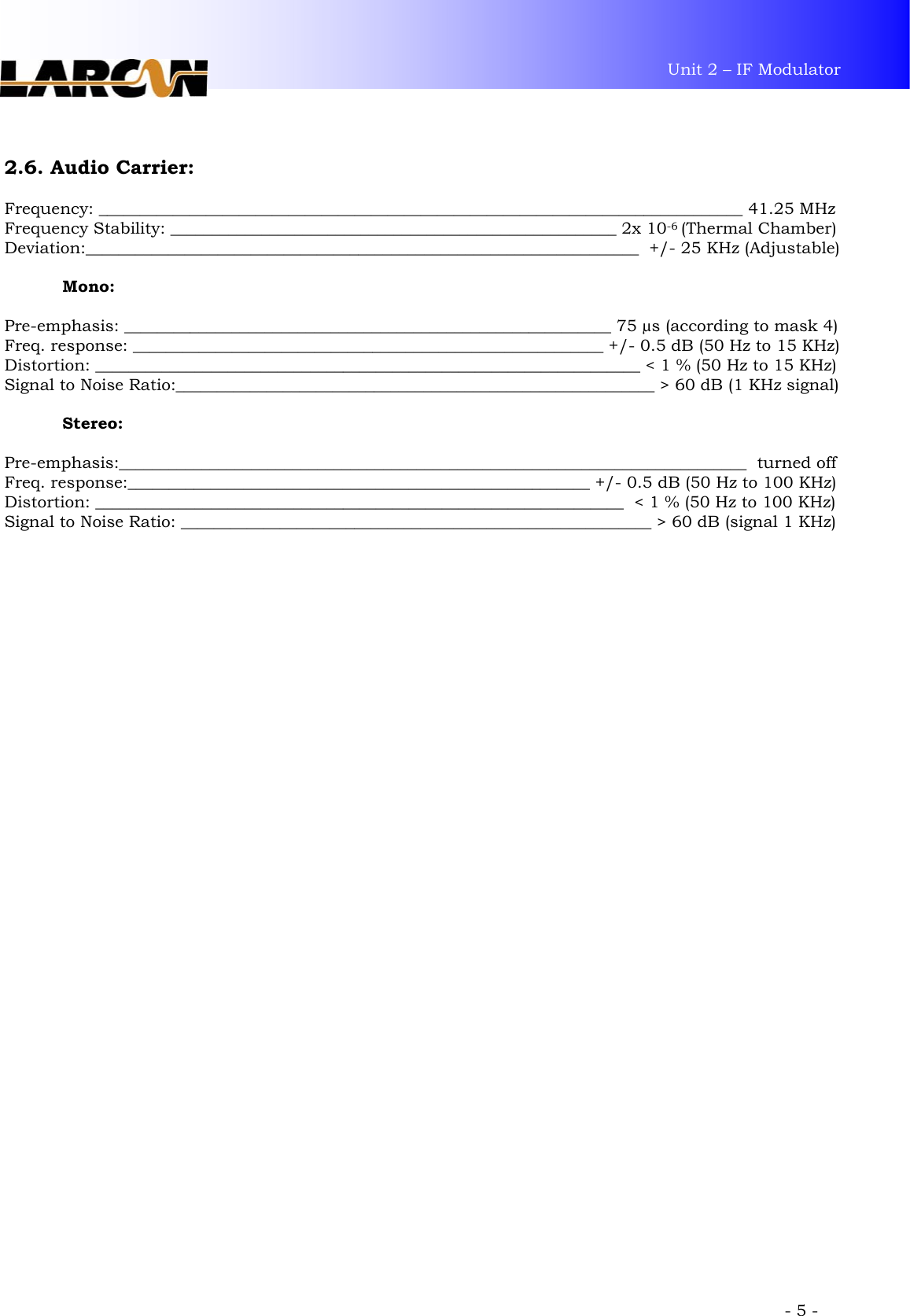
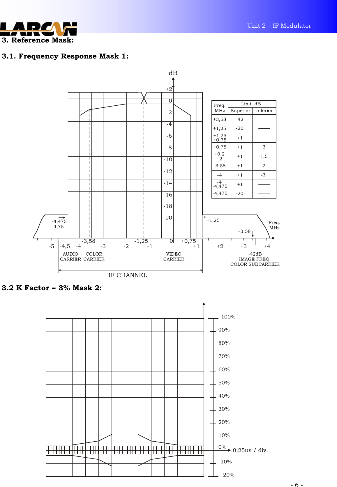
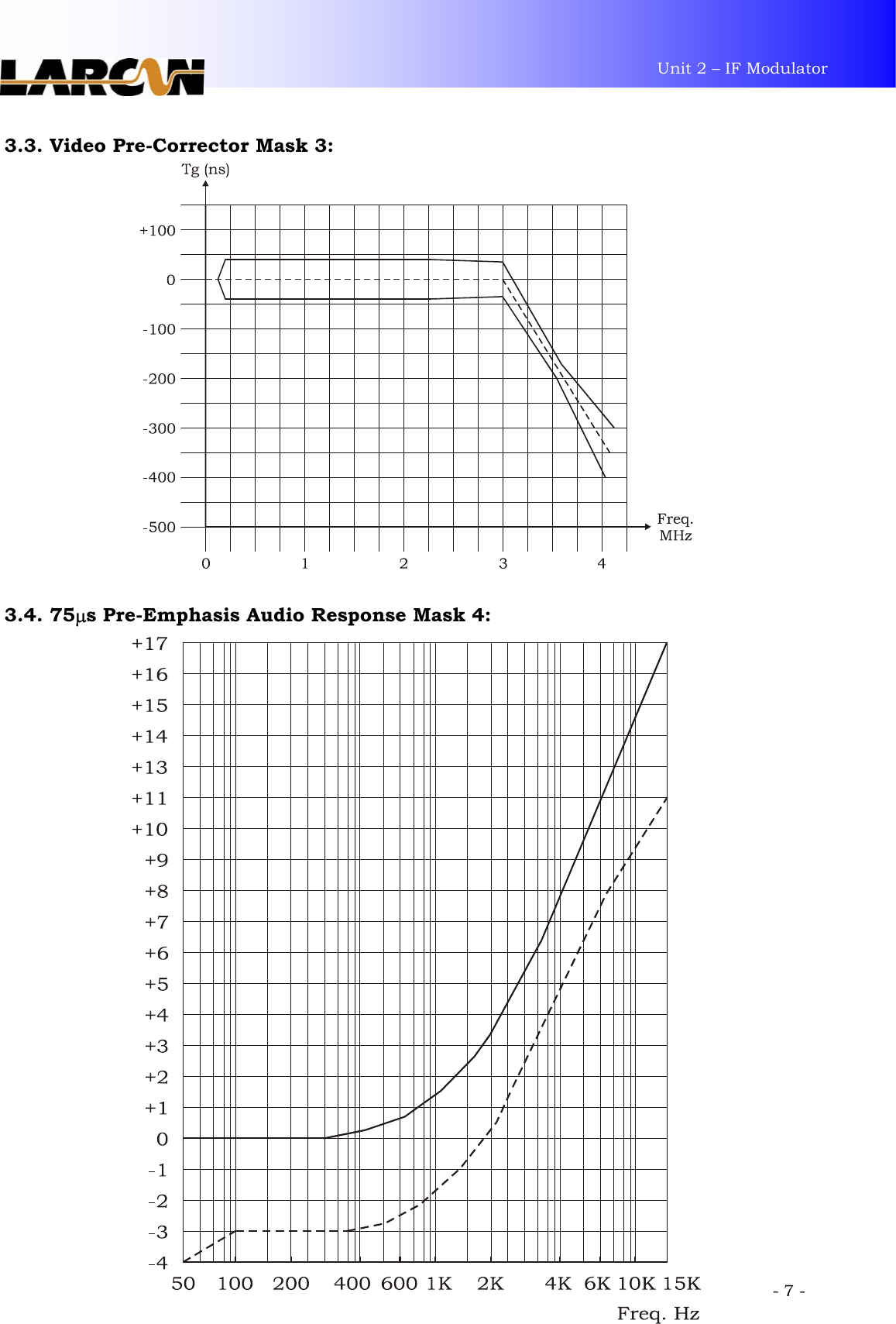
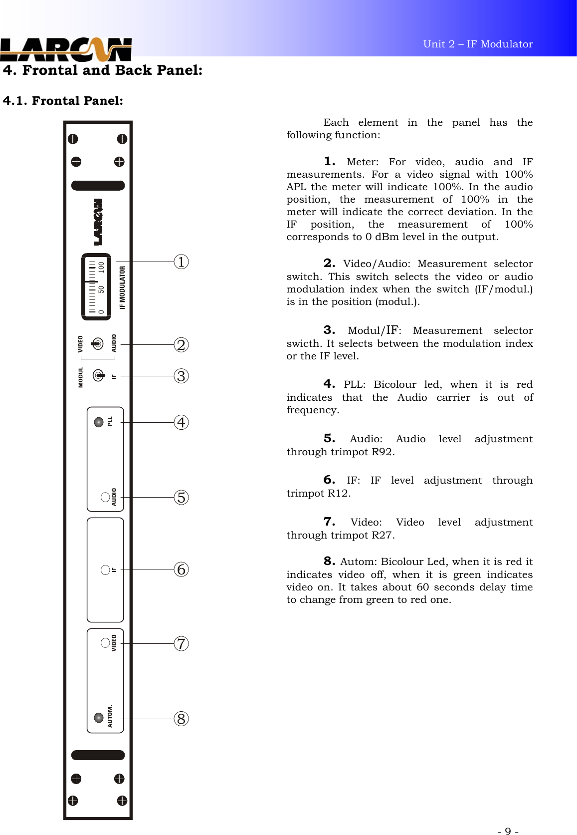
- 3. user manual for modulator
user manual for modulator