Larcan T2500U 2500 Watt UHF Transmitter User Manual RTU5000T
Larcan Inc 2500 Watt UHF Transmitter RTU5000T
Larcan >
Contents
- 1. user manual for tx part1
- 2. user manual for tx part2
- 3. user manual for modulator
user manual for tx part2

Unit 1 – Introduction
- 1 -
Meridian 2.5 kW UHF
Model T2500U
Technical Service Manual
TSM20-342
Rev. 00
August/2004

Unit 1 – Introduction
- 2 -
Contents
Unit I Introduction
1. External Layout: Page 05
2. General technical descriptive: Page 06
3. Technical Characteristics: Page 08
4. Block Diagram: Page 09
Unit II IF Modulator
1. Audio and Video Modulator Page 02
2. Technical Characteristics: Page 04
3. Reference mask: Page 06
4. Front and Back panel: Page 08
5. Circuit Diagram MAV001: Page 10
6. Layout MAV001: Page 14
7. Parts List MAV001: Page 15
8. Power Supply: Page 18
9. Power Supply (optional): Page 20
10. Measurement Circuit: Page 23
Unit III Channel UP Converter
1. Channel UP Converter: Page 02
2. Frontal and Back Panel: Page 03
3. IF Filter Amplifier: Page 06
4. IF Pre-dirtortion linearity Page 11
5. Automatic Level Control (ALC): Page 16
6. Channel UP Converter: Page 20
7. PLL Protection: Page 27
8. UP Converter supply –12, +12 and +24V: Page 29

Unit 1 – Introduction
- 3 -
Unit IV UHF 50W Amplifier
1. UHF 50W Amplifier: Page 02
2. Frontal and Back Panel: Page 03
3. Switched Power Supply +32V 14 A: Page 05
4. 50W UHF Amplifier Protections: Page 10
5. Power Detecting and Power Limiting Protection: Page 14
6. 2W UHF Amplifier: Page 16
7. 50W Output Amplifier: Page 19
8. 50W UHF Amplifier Circuit Diagram Page 23
Unit V 625W Amplifier
1. 625W Amplifier: Page 02
2. Frontal and Back Panel: Page 03
3. +32V 25 A Switched Power Supply: Page 05
4. 625W Amplifier Protections: Page 09
5. Output Supply: Page 13
6. 625W Final Amplifier: Page 15
7. 625W UHF Amplifier: Page 19
Unit VI cabling e attributes
1. Protection and Command: Page 02
2. Transient Suppressor main AC: Page 07
3. Temperature Sensor: Page 09
4. TV Monitor: Page 11
5. Meter Panel: Page 16
6. Remote monitoring: Page 20
7. Notch Filter: Page 23
8. Command and Protection Board: Page 26
9. Rack Cabling: Page 27

Unit 1 – Introduction
- 4 -

Unit 1 – Introduction
- 5 -
Unit 1 – Introduction
- 6 -
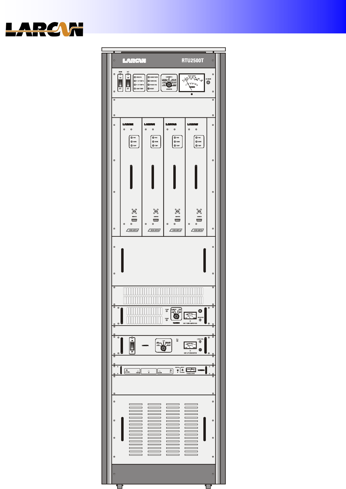
1. External Layout:

Unit 1 – Introduction
- 7 -
2. General Technical Descriptive:
2.1. IF Modulator (for transmitter):
This is the input module. It is a professional audio and video modulator. The audio and video
signals are applied to their respective input for the modulation process in IF (41 to 47 MHz]. The audio
and video input impedances are 600 balanced Ohms and 75 unbalanced Ohms, respectively.
2.1.1. Video processing:
The video signal passes through linearity correction circuits and then is applied to the 45.75
MHz video modulator. There are Synchronizing Separation circuits that generate the auxiliary outputs
to “Automatic Circuits”. The video signal is also applied to a group delay predistortion circuit.
2.1.2. Audio processing:
The Mono-audio signal or stereo base band is applied to the module and modulates a 41.25
MHz audio carrier.
2.1.3 Module output:
Both carriers, audio and video modulated (41.25 and 45.75 MHz), are applied to the “Vestigial
Side Band Filter” (SAW Filter). At the output there is a circuit to control the IF output level.
2.2. UHF UP Converter:
2.2.1. Introduction:
This module converts an IF frequency signal into an UHF band channel, keeping its
characteristics and the same bandwidth.
2.2.2. IF filter and AGC amplifier (for transposer):
The IF amplifier and filter module establishes the adequate bandwidth for the input signal and
supply the gain in this signal, keeping the level constant through an AGC loop.
2.2.3. Technical Descriptive:
The 2nd UHF converter has an oscillator controlled by PLL (Phase Locked Loop Integrated
Circuit), which frequency is selected through the DIP switch from the Oscillator control board. When
the modulated signal in IF is received in the 2nd converter, it is filtered and applied to a mixer. The
result of this mixing is filtered (channel filter) and supplied to the following modules of the equipment,
in the selected channel.

Unit 1 – Introduction
- 8 -
2.3. Amplifier Levels:
2.3.1. Comment/Composition/Origin:
The T2500U is composed for 4 625W amplifier modules combined through 3dB hybrid couplers.
The final modules are drived by a 50W amplifier and 3 dB hibrid couplers as splitters.
All the amplifiers are in solid state.
2.3.2. Protections/Signaling:
Each 625W amplifier has a VSWR protection, temperature and a power limiting circuit.
The output power, VSWR, temperature, current and module voltage can be monitored through a
DB9 connector in the front panel.
In the frontal panel there are the normal power indication (Green Led), low power (red led) and
excessive VSWR (red led). There is, also, a BNC connector for monitoring the output signal of each
module.
At the transmitter output, there is the video and audio power monitoring, antenna VSWR, power
supply antenna, current and voltage and indications of excessive VSWR, excessive filter VSWR, power
supply temperature alarm, video absence, phase fail and others.
There is at the transmitter top, a DB25 connector with transmitter signals, for remote
monitoring.
2.4. Notch filter:
It is used to attenuate out channel spurious generated by the transmitter. It is composed by 11
cavities, 10 are syntonized in the spurious frequencies and 1 in the 2nd harmonic.

Unit 1 – Introduction
- 9 -
3. Technical Characteristics:
3.1. Main Characteristics:
Model: _____________________________________________________________________________________ T2500U
Operation Band: ____________________________________________________________14 to 59 / 470-746 MHz
Intermodulation: __________________________________________________________ better than 53 dB (in red)
Power Supply: __________________________________________________________________ 220Vca three phase
Harmonic and spurious attenuation: _______________________________________________ better than 60 dB
Dimensions: ____________________________________ Width = 555mm; Height = 2100mm; Depth = 870mm
Weight: ______________________________________________________________________________________ 180Kg
Operating: ________________________________________________________________________ 2000 m (sea level)
Maximum relative humidity: _______________________________ 95% non condensing (temperature < 25°C)
Operating temperature: _________________________________________________________________ 0°C to 40°C
Recommended operating temperature: __________________________________________________ 20°C to 28°C
3.2. Video Characteristics:
Input Level: ___________________________________________________________________________ 0.7 to 1.5Vpp
Input impedance: ____________________________________________________________ 75 Ohms (asymmetric)
Output power: ____________________________________________________________________ 2500W peak sync
Output impedance: _______________________________________________________________________ 50 Ohms
Frequency Stability: ____________________________________________________________________ + or –500Hz
Harmonic and Spurious attenuation:_____________________ better than 60 dB below of the video carrier
Periodic Signal Noise ratio: _______________________________ better than 40 dB below of the video carrier
Differential Gain: _______________________________________________________ <5% to 87.5% of modulation
Differential phase: _______________________________________________________ <5° to 87.5% of modulation
Synchronism compression: ________________________________________________________ 0.5 dB maximum
Luminance and chrominance delay__________________________________________ better than + or – 30 ns
3.3. Audio Characteristics:
Input level: ___________________________________________________________ 0 dBm to 25 KHz of deviation
Input impedance: ______________________________________________________________ 600 Ohms balanced
Output power: ________________________________________________________________________________ 250W
Output impedance: _______________________________________________________________________ 50 Ohms
Frequency Stability: ___________________________________________________________________ + or – 500 Hz
Audio Response: ___________________________ + or – 1 dB, 50 Hz to 15 KHz (with 75 µs of pre-emphasis)
AM Noise: _________________________________ 50 dB below the correspondent level for 100% modulation
FM Noise: _________________________________ 53 dB below the correspondent level for 100% modulation
Harmonic Attenuation: ____________________________________________________________ better than 60 dB
3.4. Supplementary Characteristics:
Input Connector: ______________________________________________________ audio = cannon; video = BNC
Output Connector:_________________________________________________________________ flange EIA 1 5/8”
Maximum consumption:______________________________________________________________________ 15
kVA
Final Stage: ________________________________________________________________ 64 x MRF373A (LDMOS)
Unit 1 – Introduction
- 10 -
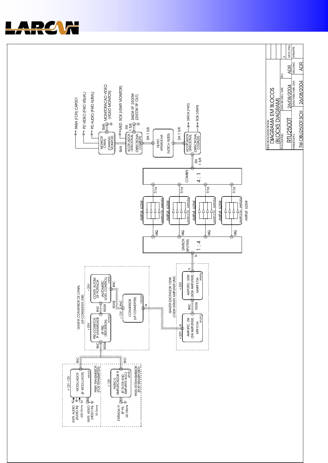
4. Block Diagram: