Launch Tech CRP429HD Professional HD Diagnostic Tool User Manual 15 CRP 429HD UserMan
Launch Tech Co., Ltd. Professional HD Diagnostic Tool 15 CRP 429HD UserMan
UserManual.wiki
>
Launch Tech
>
CRP429HD User Manual
15_CRP 429HD UserMan
Navigation menu
Upload a User Manual
Namespaces
Wiki Guide
HTML
PDF
Info
Views
User Manual
Discussion / Help
Navigation

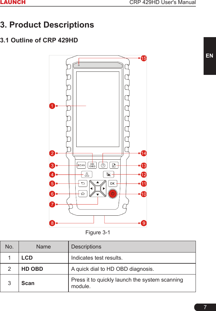
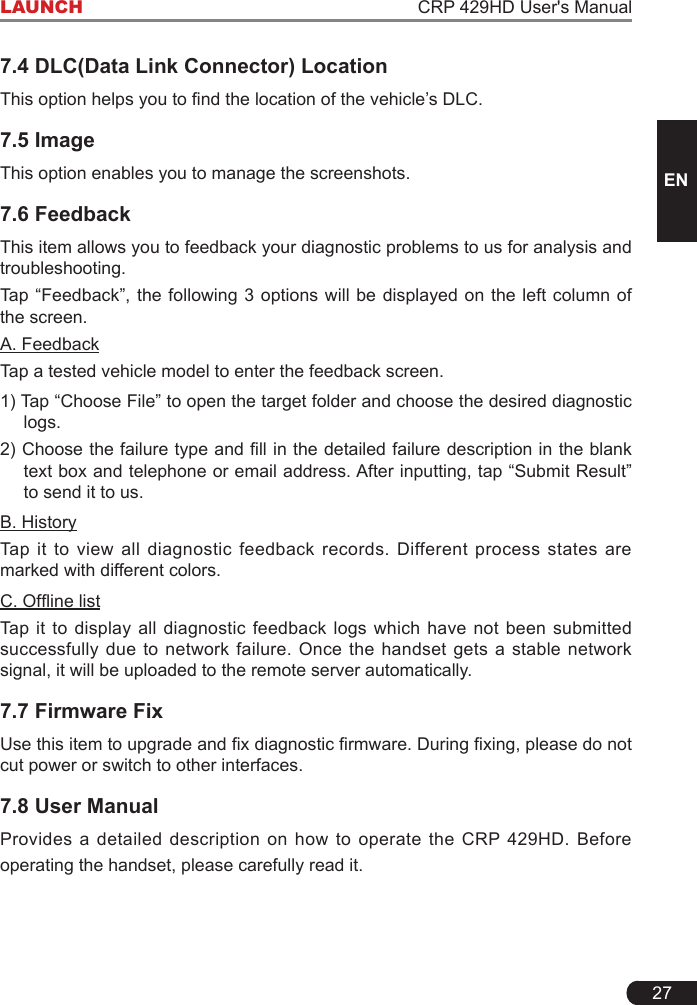
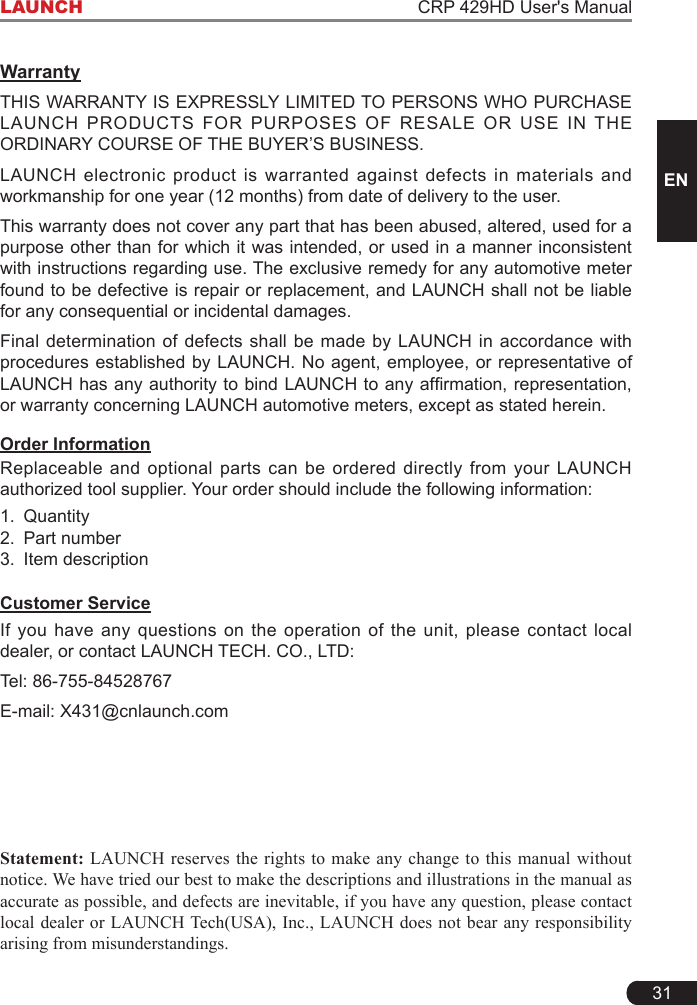
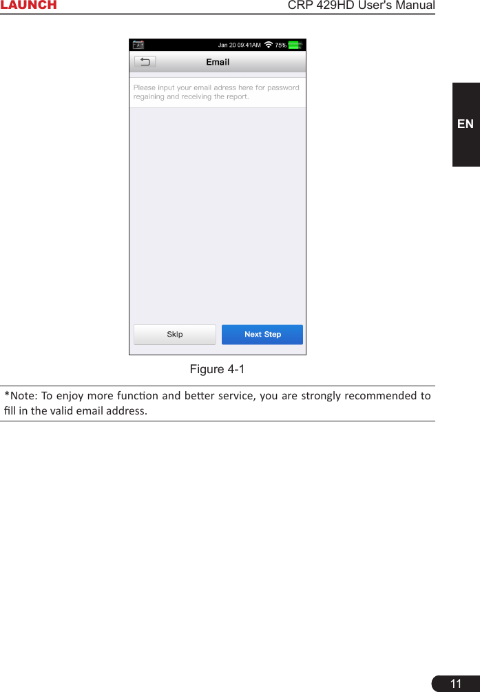
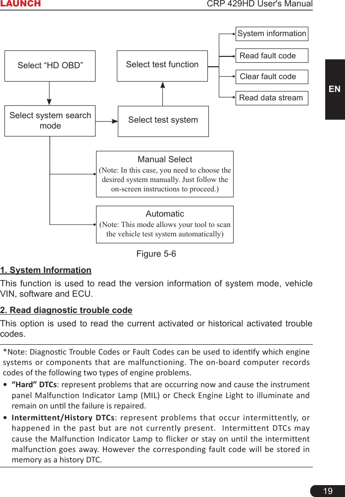
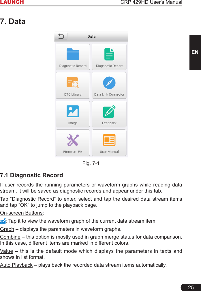
![10LAUNCH CRP 429HD User's Manual4. Initial Use4.1 Charging CRP 429HDThere are two charging methods available:Via Charging Cable: Plug one end of the included charging cable into the DC-IN port of the tool, and the other end to the external DC power.Via Diagnostic Cable: Insert one end of the diagnostic cable into the DB-15 connector of the tool, and the other end to the vehicle’s DLC (*For vehicles equipped with non-16pin DLC, a non-16pin adaptor cable is required).Once the charging LED illuminates solid green, it indicates that the battery is fully charged.4.2 Getting StartedIf it is the first time you have used this tool, you need to make some system settings.1. Press the [Power] button to power it on.2. The screen displays a welcome page. Tap “Start” to go to next step.3. Choose the desired system language, and tap “Next”.4. Choose the desired time zone, and tap “Next” to enter the WLAN setup page.5. Slide the switch to ON, the system starts searching for all available wireless LANs. Choose the desired WLAN access point / network,• If the network you chose is open, you can connect directly;• If the selected network is encrypted, you have to enter the right security key (network password). *Note: If you choose “Ignore” in WLAN setup, it will go into the date seng page. If the tool has been properly connected to the Internet, the system will automacally obtain the correct network date and me and navigate to step 6. 6.Afterthenetworkconnectionisdone,tap“Next”tocongureemailaddress.Input the email address, and tap “Next” to navigate to the Job menu.](https://usermanual.wiki/Launch-Tech/CRP429HD/User-Guide-3968566-Page-16.png)
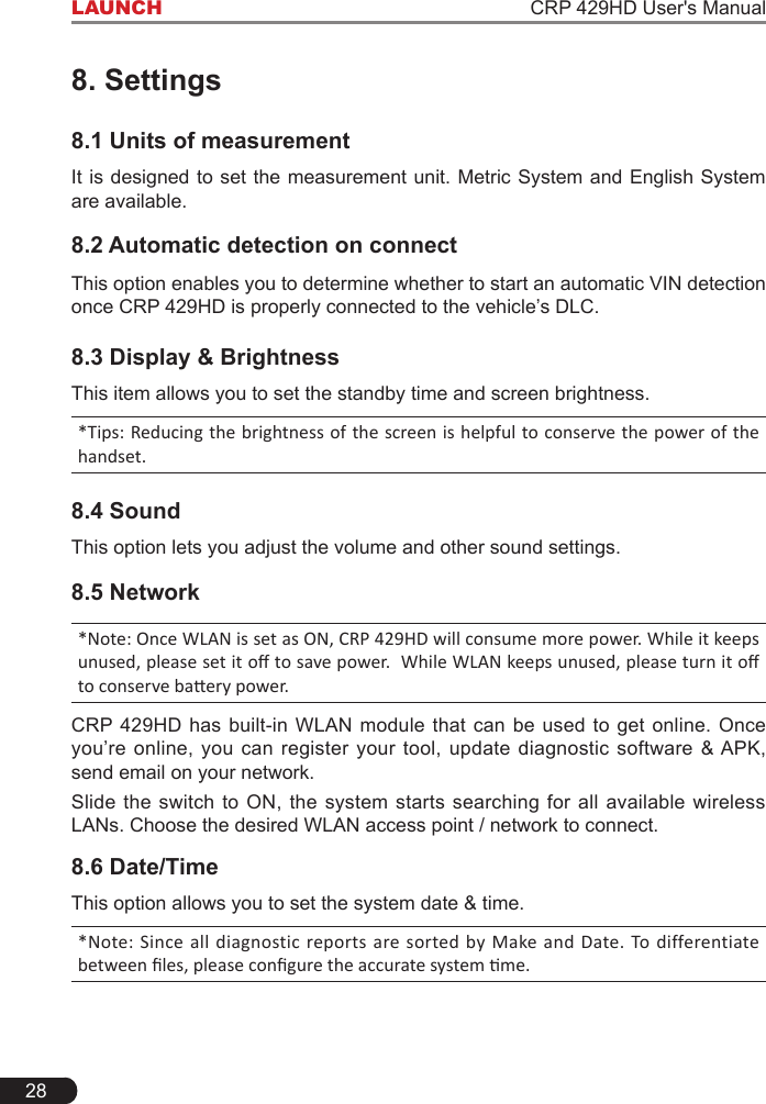
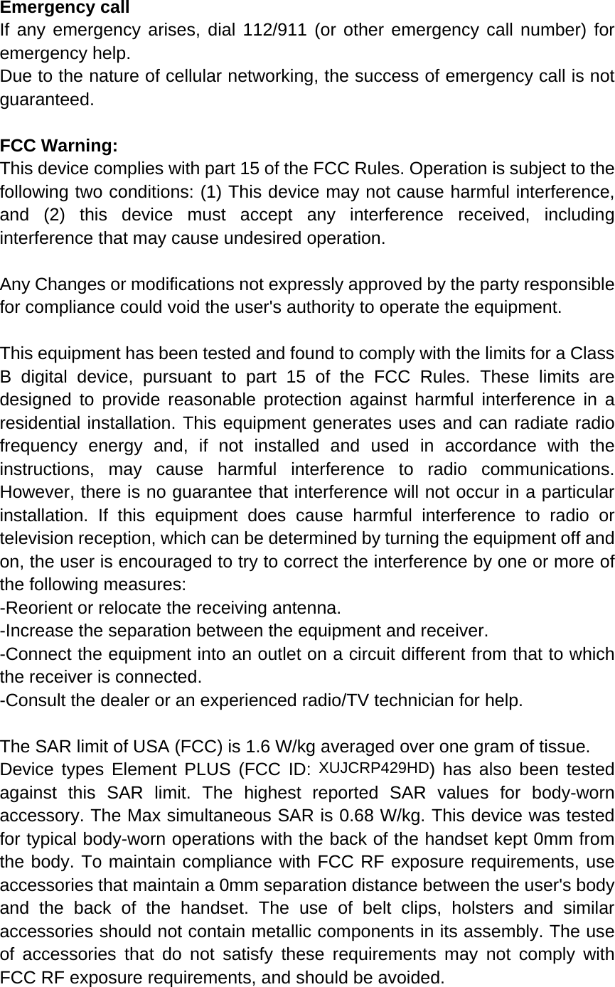
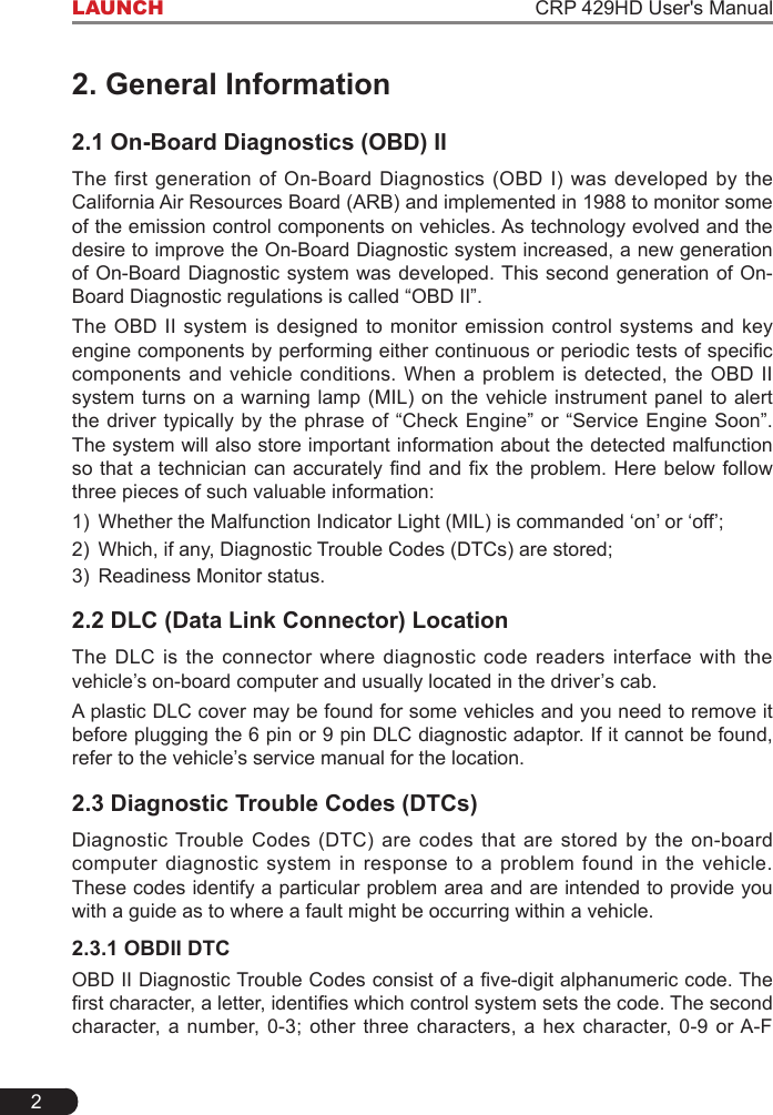
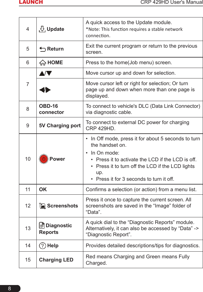
![20LAUNCH CRP 429HD User's ManualGenerally, there are three elements for one J1939 DTC (See Figure 5-7):• SuspectParameterNumber(SPN)–IndicateswhatfunctionontheECUhasfailed.• FailureModeIndicator(FMI)–Indicatesinwhatwaythefunctionfailed.• Occurence(OC)–IndicatestheoccurencetimesofthecurrentDTC.Whereas, if we choose [J1587/1708], the fault code includes: • SubsystemIdentier(SID)–IndicateswhatfunctionontheECUhasfailed.• FailureModeIndicator(FMI)–Indicatesinwhatwaythefunctionfailed.• Occurence(OC)–IndicatestheoccurencetimesofthecurrentDTC.*Note: Retrieving and using DTCs for troubleshooting vehicle operation is only one part of an overall diagnostic strategy. Never replace a part based only on the DTC denion. Each DTC has a set of tesng procedures, instrucons and ow charts that must be followed to confirm the location of the problem. This information can be found in the vehicle’s service manual.3. Clear diagnostic trouble codeThis option allows you to clear the existing or historic trouble codes. ClearingDTCsdoesnotxtheproblem(s)thatcausedthecode(s)tobeset.Ifproper repairs to correct the problem that caused the code(s) to be set are not made, the code(s) will appear again and the check engine light will illuminate as soon as the problem that cause the DTC to set manifests itself.*Note: Aer clearing, you should retrieve trouble codes once more or turn ignion on and retrieve codes again. If there are still some trouble codes in the system, please troubleshoot the code using a factory diagnosis guide, then clear the code and recheck.4. Data streamThis option enables you to read the real-time data stream in character or graphic form. *Note: If you must drive the vehicle in order to perform a troubleshoong procedure, ALWAYS have a second person help you. Trying to drive and operate the CRP 429HD at the same me is dangerous, and could cause a serious trac accident. 5.3.2 EOBDII DiagnosingOn Fig. 5-5, tap [EOBD II] to start initializing. Once the initialization is complete, a screen displaying Monitor Status appears. Tap [OK] to enter the function selection page.](https://usermanual.wiki/Launch-Tech/CRP429HD/User-Guide-3968566-Page-26.png)
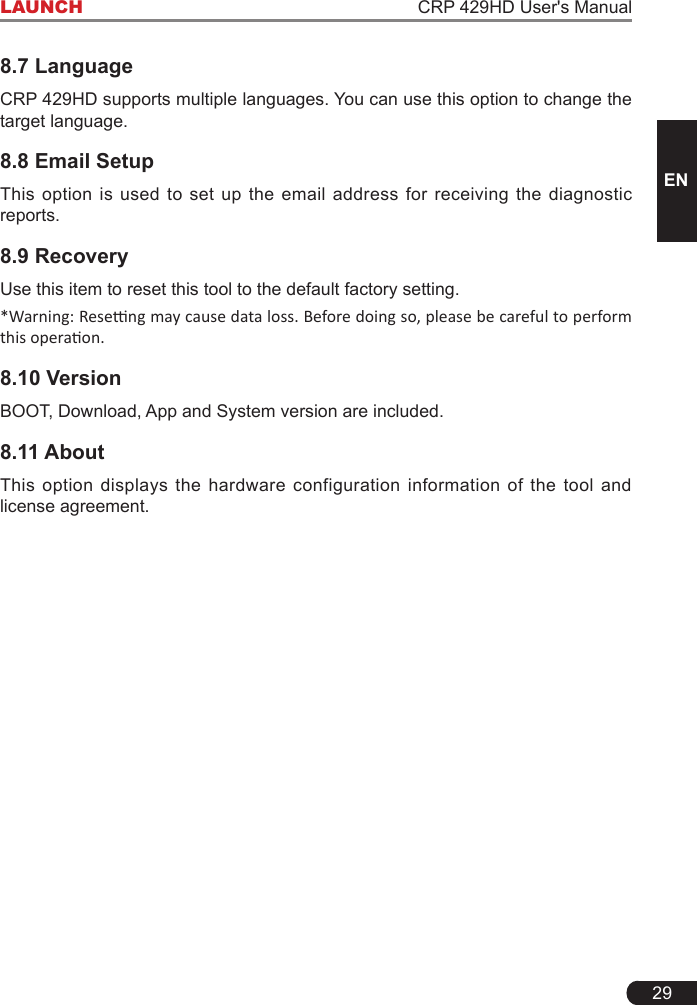
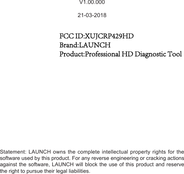
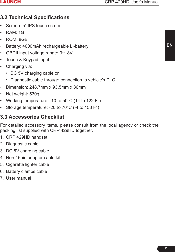
![26LAUNCH CRP 429HD User's Manual7.2 Diagnostic ReportThis module stores all diagnostic reports generated in process of vehicle diagnosis. All the diagnostic reports are sorted by Date and Make. If there are too many reports stored, tap (Search)tolterandquicklylocateit.• To select certain report, just check the box at the lower right corner of the report. To select all reports, tap “Select All”. To deselect all, tap “Unselect”.• Tap it to view its details.• Select the desired report and then tap “Delete” to delete it.7.3 DTC LibraryThisoptionhelpsyoutondthelocationofthevehicle’sDLC.Fig. 7-2Swipe the screen upwards/downwards to alter the value, then press [OK] button, thescreenwilldisplaydenitionoftheDTC.](https://usermanual.wiki/Launch-Tech/CRP429HD/User-Guide-3968566-Page-32.png)