Launch Tech CRP429HD Professional HD Diagnostic Tool User Manual 15 CRP 429HD UserMan
Launch Tech Co., Ltd. Professional HD Diagnostic Tool 15 CRP 429HD UserMan
15_CRP 429HD UserMan
V1.00.000
21-03-2018
Statement: LAUNCH owns the complete intellectual property rights for the
software used by this product. For any reverse engineering or cracking actions
against the software, LAUNCH will block the use of this product and reserve
the right to pursue their legal liabilities.
FCC ID:XUJCRP429HD
Brand:LAUNCH
Product:Professional HD Diagnostic Tool

i
LAUNCH CRP 429HD User's Manual
EN
Trademark Information
LAUNCH is a registered trademark of LAUNCH TECH CO., LTD. (LAUNCH)
in China and other countries. All other LAUNCH trademarks, service marks,
domain names, logos and company names referred to in this manual are either
trademarks, registered trademarks, service marks, domain names, logos and
company names of or are otherwise the property of LAUNCH or its affiliates.
In countries where any of the LAUNCH trademarks, service marks, domain
names, logos and company names are not registered, LAUNCH claims other
rights associated with unregistered trademarks, service marks, domain names,
logos and company names. Other products or company names referred to in
this manual may be trademarks of their respective owners. You may not use any
trademark, service mark, domain name, logo, or company name of LAUNCH or
any third party without permission from the owner of the applicable trademark,
service mark, domain name, logo, or company name. You may contact LAUNCH
at www.cnlaunch.com, or write to LAUNCH TECH. CO., LTD., Launch Industrial
Park, North of Wuhe Avenue, Banxuegang, Bantian, Longgang, Shenzhen,
Guangdong, P.R. China, to request written permission to use Materials on this
manual for purposes or for all other questions relating to this manual.
Copyright Information
Copyright © 2018 by LAUNCH TECH. CO., LTD. All rights reserved. No part of
this publication may be reproduced, stored in a retrieval system, or transmitted in
any form or by any means, electronic, mechanical, photocopying and recording
or otherwise, without the prior written permission of LAUNCH. The information
contained herein is designed only for the use of this unit. LAUNCH is not
responsible for any use of this information as applied to other units.
General Notice
• Other product names used herein are for identification purposes only and
may be trademarks of their respective owners. LAUNCH disclaims any and all
rights in those marks.
• There is a possibility that this unit is inapplicable to some of the vehicle
models or systems listed in the diagnosis section due to different countries,
areas, and/or years. Do not hesitate to contact LAUNCH if you come across
such questions. We are to help you solve the problem as soon as possible.
Disclaimer
• To take full advantage of the unit, you should be familiar with the engine.
• Allinformation,illustrations,andspecicationscontainedinthismanualare
based on the latest information available at the time of publication. The right

ii
LAUNCH CRP 429HD User's Manual
is reserved to make change at any time without notice.
• NeitherLAUNCHnoritsafliatesshallbeliabletothepurchaserofthisunit
or third parties for damages, losses, costs or expenses incurred by purchaser
or third parties as a result of: accident, misuse, or abuse of this unit, or
unauthorized modifications, repairs, or alterations to this unit, or failure to
strictly comply with LAUNCH operating and maintenance instructions.
• LAUNCH shall not be liable for any damages or problems arising from the
use of any options or any consumable products other than those designated
as Original LAUNCH Products or LAUNCH Approved Products by LAUNCH.
Safety Precautions and Warnings
To prevent personal injury or damage to vehicles and/or the CRP 429HD,
pleasereadthisuser’smanualrstcarefullyandobservethefollowingsafety
precautions at a minimum whenever working on a vehicle:
• Always perform automotive testing in a safe environment.
• Do not attempt to operate or observe the tool while driving a vehicle.
Operating or observing the tool will cause driver distraction and could cause a
fatal accident.
• Wear safety eye protection that meets ANSI standards.
• Keep clothing, hair, hands, tools, test equipment, etc. away from all moving or
hot engine parts.
• Operate the vehicle in a well-ventilated work area: Exhaust gases are
poisonous.
• Put blocks in front of the drive wheels and never leave the vehicle unattended
while running tests.
• Use extreme caution when working around the ignition coil, distributor cap,
ignition wires and spark plugs. These components create hazardous voltages
when the engine is running.
• Put the transmission in P (for A/T) or N (for M/T) and make sure the parking
brake is engaged.
• Keepareextinguishersuitableforgasoline/chemical/electricalresnearby.
• Don’t connect or disconnect any test equipment while the ignition is on or the
engine is running.
• Keep the CRP 429HD dry, clean, free from oil/water or grease. Use a mild
detergent on a clean cloth to clean the outside of the CRP 429HD, when
necessary.
• Please use the DC 5V power adaptor to charge the CRP 429HD. No

iii
LAUNCH CRP 429HD User's Manual
EN
responsibility can be assumed for any damage or loss caused as a result of
using power adaptors other than the right one.
FCC Warning:
This device complies with part 15 of the FCC Rules. Operation is subject to the
following two conditions: (1) This device may not cause harmful interference,
and (2) this device must accept any interference received, including interference
that may cause undesired operation.
AnyChangesormodicationsnotexpresslyapprovedbythepartyresponsible
for compliance could void the user’s authority to operate the equipment.
This equipment has been tested and found to comply with the limits for a Class
B digital device, pursuant to part 15 of the FCC Rules. These limits are designed
to provide reasonable protection against harmful interference in a residential
installation. This equipment generates uses and can radiate radio frequency
energy and, if not installed and used in accordance with the instructions, may
cause harmful interference to radio communications. However, there is no
guarantee that interference will not occur in a particular installation. If this
equipment does cause harmful interference to radio or television reception,
which can be determined by turning the equipment off and on, the user is
encouraged to try to correct the interference by one or more of the following
measures:
- Reorient or relocate the receiving antenna.
- Increase the separation between the equipment and receiver.
- Connect the equipment into an outlet on a circuit different from that to which
the receiver is connected.
- Consult the dealer or an experienced radio/TV technician for help.
The device has been evaluated to meet general RF exposure requirement.
The SAR limit of USA (FCC) is 1.6 W/kg averaged over one gram of tissue.
Device types Professional Diagnostic Tool with model CRP 429HD (FCC ID:
XUJCRP429HD) has also been tested against this SAR limit. The highest
reported SAR values for body-worn is 0.68 W/kg. This device was tested for
typical body-worn operations with the back of the handset kept 0mm from the
body. The use of accessories that do not satisfy these requirements may not
comply with FCC RF exposure requirements, and should be avoided.

iv
LAUNCH CRP 429HD User's Manual
Table of Contents
1. Introduction .....................................................................................................1
2. General Information .......................................................................................2
2.1 On-Board Diagnostics (OBD) II ......................................................................2
2.2 DLC (Data Link Connector) Location..............................................................2
2.3 Diagnostic Trouble Codes (DTCs) ..................................................................2
2.3.1 OBDII DTC..............................................................................................2
2.3.2 DTCs for J1587/J1708 and J1939 .......................................................... 3
2.4 J1708/J1587/J1939 ........................................................................................4
2.5OBDIIDenitions ...........................................................................................5
3. Product Descriptions .....................................................................................7
3.1 Outline of CRP 429HD ...................................................................................7
3.2TechnicalSpecications .................................................................................9
3.3 Accessories Checklist ..................................................................................... 9
4. Initial Use.......................................................................................................10
4.1 Charging CRP 429HD ..................................................................................10
4.2 Getting Started .............................................................................................10
5. Diagnose .......................................................................................................13
5.1 Connection ...................................................................................................13
5.2 System Diagnosing.......................................................................................13
5.2.1 System Scan.........................................................................................13
5.2.2 Manual Diagnosis .................................................................................15
5.3 HD OBD Diagnosis ....................................................................................... 18
5.3.1 HD OBD Diagnosing ............................................................................. 18
5.3.2 EOBDII Diagnosing...............................................................................20
5.4 History ..........................................................................................................23
6. Update ...........................................................................................................24
7. Data ................................................................................................................ 25
7.1 Diagnostic Record ........................................................................................25
7.2 Diagnostic Report .........................................................................................26
7.3 DTC Library ..................................................................................................26

v
LAUNCH CRP 429HD User's Manual
EN
7.4 DLC(Data Link Connector) Location.............................................................27
7.5 Image............................................................................................................27
7.6 Feedback ...................................................................................................... 27
7.7 Firmware Fix ................................................................................................. 27
7.8 User Manual .................................................................................................27
8. Settings .........................................................................................................28
8.1 Units of measurement ..................................................................................28
8.2 Automatic detection on connect....................................................................28
8.3 Display & Brightness ....................................................................................28
8.4 Sound ...........................................................................................................28
8.5 Network ........................................................................................................28
8.6 Date/Time .....................................................................................................28
8.7 Language......................................................................................................29
8.8 Email Setup ..................................................................................................29
8.9 Recovery ......................................................................................................29
8.10 Version........................................................................................................29
8.11 About ...........................................................................................................29
9. FAQ ................................................................................................................30

1
LAUNCH CRP 429HD User's Manual
EN
1. Introduction
CRP 429HD is an evolutionary smart solution exclusively for commercial vehicle
diagnosis. It inherits from LAUNCH’s advanced diagnosing technology and is
characterized by covering a wide range of vehicles, featuring powerful functions,
and providing precise test result.
CRP 429HD has the following functions and advantages:
• SystemDetect Diagnosis: This option provides the ability to quickly access the
vehicle system. Once CRP 429HD and the vehicle are properly connected,
the system starts auto-decoding process.
Oncethewholeprocessissuccessfullynished,youcanstartadiagnostic
session for each system.
• Manual Diagnosis: If SystemDetect failure occurs, manual diagnosis is also
available. Diagnosis functions include: Version Information, Read DTCs,
Clear DTCs and Read Data Stream (supports 3 display modes: Value, Graph
and Merged).
• HD OBD Diagnosis: 10 modes of OBD II test are supported, including EVAP,
O2 Sensor, I/M Readiness, MIL Status, VIN Info, and On-board monitors
testing etc.
• One-click Update: Let you update your diagnostic software and APK online.
• Diagnostic History: This function provides a quick access to the tested
vehicles and users can choose to view the test report or resume from the last
operation, without the necessity of starting from scratch.
• Diagnostic Feedback: Use this option to submit the vehicle issue to us for
analysis and troubleshooting.
• DTC Library: Allows you to retrieve the definition of the diagnostic trouble
code from the abundant DTC database.
• Displays battery real-time voltage once properly connected to the vehicle.
• Features screenshot capture. Screenshots and reports sharing are supported.
• Touch & Keypad input are supported. Quick Dial buttons enables you to easily
access the corresponding functions.

2
LAUNCH CRP 429HD User's Manual
2. General Information
2.1 On-Board Diagnostics (OBD) II
The first generation of On-Board Diagnostics (OBD I) was developed by the
California Air Resources Board (ARB) and implemented in 1988 to monitor some
of the emission control components on vehicles. As technology evolved and the
desire to improve the On-Board Diagnostic system increased, a new generation
of On-Board Diagnostic system was developed. This second generation of On-
Board Diagnostic regulations is called “OBD II”.
The OBD II system is designed to monitor emission control systems and key
enginecomponentsbyperformingeithercontinuousorperiodictestsofspecic
components and vehicle conditions. When a problem is detected, the OBD II
system turns on a warning lamp (MIL) on the vehicle instrument panel to alert
the driver typically by the phrase of “Check Engine” or “Service Engine Soon”.
The system will also store important information about the detected malfunction
sothatatechniciancanaccuratelyndandxtheproblem.Herebelowfollow
three pieces of such valuable information:
1) Whether the Malfunction Indicator Light (MIL) is commanded ‘on’ or ‘off’;
2) Which, if any, Diagnostic Trouble Codes (DTCs) are stored;
3) Readiness Monitor status.
2.2 DLC (Data Link Connector) Location
The DLC is the connector where diagnostic code readers interface with the
vehicle’s on-board computer and usually located in the driver’s cab.
A plastic DLC cover may be found for some vehicles and you need to remove it
before plugging the 6 pin or 9 pin DLC diagnostic adaptor. If it cannot be found,
refer to the vehicle’s service manual for the location.
2.3 Diagnostic Trouble Codes (DTCs)
Diagnostic Trouble Codes (DTC) are codes that are stored by the on-board
computer diagnostic system in response to a problem found in the vehicle.
These codes identify a particular problem area and are intended to provide you
with a guide as to where a fault might be occurring within a vehicle.
2.3.1 OBDII DTC
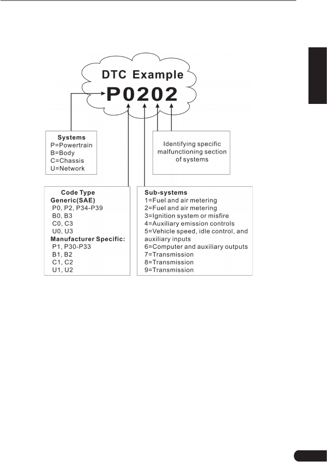
OBDIIDiagnosticTroubleCodesconsistofave-digitalphanumericcode.The
rstcharacter,aletter,identieswhichcontrolsystemsetsthecode.Thesecond
character, a number, 0-3; other three characters, a hex character, 0-9 or A-F
3
LAUNCH CRP 429HD User's Manual
EN
provide additional information on where the DTC originated and the operating
conditions that caused it to set. Here below is an example to illustrate the
structure of the digits:
2.3.2 DTCs for J1587/J1708 and J1939
This section explains the basic elements of fault codes for J1587/J1708 and
J1939 data bus protocols, how to view these codes on CRP 429HD HD, and
what they mean. Each fault code on CRP 429HD HD contain three distinct
pieces of information, as described below.
J1587/J1708 fault codes consist of the following, in this order:
• SubsystemIdentier(SID)–IndicateswhatfunctionontheECUhasfailed.
• FailureModeIndicator(FMI)–Indicatesinwhatwaythefunctionfailed.
• Occurence(OC)–Indicatestheoccurencetimesoffaultcodes.
J1939 fault codes consist of the following, in this order:
• SuspectParameterNumber(SPN)–IndicateswhatfunctionontheECUhas
failed.

4
LAUNCH CRP 429HD User's Manual
• FailureModeIndicator(FMI)–Indicatesinwhatwaythefunctionfailed.
• Occurence(OC)–Indicatestheoccurencetimesoffaultcodes.
2.4 J1708/J1587/J1939
SAE J1708, SAE J1587 and SAE J1939 are automotive diagnostic protocol
standard developed by the Society of Automotive Engineers (SAE).
SAE J1708
SAE J1708 is a standard used for serial communications between ECUs on a
heavy duty vehicle and also between a computer and the vehicle. With respect
toOpenSystemInterconnectionmodel(OSI),J1708denesthephysicallayer.
Common higher layer protocols that operate on top of J1708 are SAE J1587 and
SAE J1922.
SAE J1587
SAE J1587 is an automotive diagnostic protocol standard developed by the
Society of Automotive Engineers (SAE) for heavy-duty and most medium-
duty vehicles built after 1985. The J1587 protocol uses different diagnostic
connectors. Up to 1995, individual OEMs used their own connectors. From 1996
to 2001, the 6-pin Deutsch-connector was standard. Beginning in 2001, most
OEMs converted to the 9-pin Deutsch. Some OEMs still use the 6-pin Deutsch.
It has mostly been used for US made vehicles, and also by Volvo.
SAE J1708 makes up the physical and data link layers while SAE J1587 makes
up the transport and application layers with respect to the OSI model. SAE
J1587 is used in conjunction with SAE J1708 for automobile communication.
SAE J1939
SAE J1939 is the vehicle bus standard used for communication and diagnostics
among vehicle components, originally by the car and heavy duty truck industry in
the United States.
SAE J1939 is used in the commercial vehicle area for communication throughout
the vehicle. With a different physical layer it is used between the tractor and
trailer.ThisisspeciedinISO11992.
SAE J1939 can be considered the replacement for the older SAE J1708 and
SAEJ1587specications.
SAE J1939 has been adopted widely by diesel engine manufacturers. One
driving force behind this is the increasing adoption of the engine Electronic
Control Unit (ECU), which provides one method of controlling exhaust gas
emissions within US and European standards. Consequently, SAE J1939 can
now be found in a range of diesel-powered applications: vehicles (on- and off-

5
LAUNCH CRP 429HD User's Manual
EN
road), marine propulsion, power generation and industrial pumping.
Applications of J1939 now include off-highway, truck, bus, and even some
passenger car applications.
2.5 OBD II Denitions
Powertrain Control Module (PCM) -- OBD II terminology for the on-board
computer that controls engine and drive train.
Malfunction Indicator Light (MIL) -- Malfunction Indicator Light (Service Engine
Soon, Check Engine) is a term used for the light on the instrument panel. It
is to alert the driver and/or the repair technician that there is a problem with
one or more of vehicle’s systems and may cause emissions to exceed federal
standards. If the MIL illuminates with a steady light, it indicates that a problem
has been detected and the vehicle should be serviced as soon as possible.
Undercertainconditions,thedashboardlightwillblinkorash.Thisindicatesa
severe problem and flashing is intended to discourage vehicle operation. The
vehicle onboard diagnostic system cannot turn the MIL off until the necessary
repairs are completed or the condition no longer exists.
DTC -- Diagnostic Trouble Codes (DTC) that identifies which section of the
emission control system has malfunctioned.
Enabling Criteria -- Also termed Enabling Conditions. They are the vehicle-
speciceventsorconditionsthatmustoccurwithintheenginebeforethevarious
monitors will set, or run. Some monitors require the vehicle to follow a prescribed
“drive cycle” routine as part of the enabling criteria. Drive cycles vary among
vehicles and for each monitor in any particular vehicle. Please refer to the
vehicle’sfactoryservicemanualforspecicenablingprocedures.
OBD II Drive Cycle -- A specific mode of vehicle operation that provides
conditions required to set all the readiness monitors applicable to the vehicle to
the “ready” condition. The purpose of completing an OBD II drive cycle is to force
the vehicle to run its onboard diagnostics. Some form of a drive cycle needs to
be performed after DTCs have been erased from the PCM’s memory or after
the battery has been disconnected. Running through a vehicle’s complete drive
cycle will “set” the readiness monitors so that future faults can be detected. Drive
cycles vary depending on the vehicle and the monitor that needs to be reset. For
vehiclespecicdrivecycle,consulttheservicemanual.
Freeze Frame Data -- When an emissions related fault occurs, the OBD II
system not only sets a code but also records a snapshot of the vehicle operating
parameters to help in identifying the problem. This set of values is referred to
as Freeze Frame Data and may include important engine parameters such as
engineRPM,vehiclespeed,airow,engineload,fuelpressure,fueltrimvalue,

6
LAUNCH CRP 429HD User's Manual
engine coolant temperature, ignition timing advance, or closed loop status.
Fuel Trim (FT) - Feedback adjustments to the base fuel schedule. Short-term
fuel trim refers to dynamic or instantaneous adjustments. Long-term fuel trim
refers to much more gradual adjustments to the fuel calibration schedule than
short-term trim adjustments. These long-term adjustments compensate for
vehicle differences and gradual changes that occur over time.
7
LAUNCH CRP 429HD User's Manual
EN
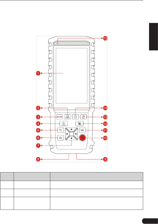
3. Product Descriptions
3.1 Outline of CRP 429HD
Figure 3-1
No. Name Descriptions
1LCD Indicates test results.
2HD OBD A quick dial to HD OBD diagnosis.
3Scan Press it to quickly launch the system scanning
module.
8
LAUNCH CRP 429HD User's Manual
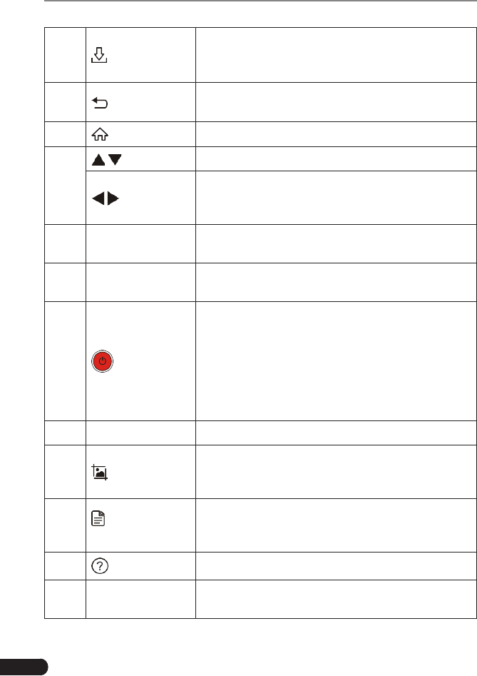
4 Update
A quick access to the Update module.
*Note: This funcon requires a stable network
connecon.
5 Return Exit the current program or return to the previous
screen.
6 HOME Press to the home(Job menu) screen.
7
/Move cursor up and down for selection.
/
Move cursor left or right for selection; Or turn
page up and down when more than one page is
displayed.
8OBD-16
connector
To connect to vehicle's DLC (Data Link Connector)
via diagnostic cable.
95V Charging port To connect to external DC power for charging
CRP 429HD.
10 Power
• In Off mode, press it for about 5 seconds to turn
the handset on.
• In On mode:
• Press it to activate the LCD if the LCD is off.
• Press it to turn off the LCD if the LCD lights
up.
• Press it for 3 seconds to turn it off.
11 OK Conrmsaselection(oraction)fromamenulist.
12 Screenshots
Press it once to capture the current screen. All
screenshots are saved in the “Image” folder of
“Data”.
13 Diagnostic
Reports
A quick dial to the “Diagnostic Reports” module.
Alternatively, it can also be accessed by “Data” ->
“Diagnostic Report”.
14 Help Provides detailed descriptions/tips for diagnostics.
15 Charging LED Red means Charging and Green means Fully
Charged.

9
LAUNCH CRP 429HD User's Manual
EN
3.2 Technical Specications
• Screen: 5” IPS touch screen
• RAM: 1G
• ROM: 8GB
• Battery: 4000mAh rechargeable Li-battery
• OBDII input voltage range: 9~18V
• Touch & Keypad input
• Charging via:
• DC 5V charging cable or
• Diagnostic cable through connection to vehicle’s DLC
• Dimension: 248.7mm x 93.5mm x 36mm
• Net weight: 530g
• Working temperature: -10 to 50°C (14 to 122 F°)
• Storage temperature: -20 to 70°C (-4 to 158 F°)
3.3 Accessories Checklist
For detailed accessory items, please consult from the local agency or check the
packing list supplied with CRP 429HD together.
1. CRP 429HD handset
2. Diagnostic cable
3. DC 5V charging cable
4. Non-16pin adaptor cable kit
5. Cigarette lighter cable
6. Battery clamps cable
7. User manual

10
LAUNCH CRP 429HD User's Manual
4. Initial Use
4.1 Charging CRP 429HD
There are two charging methods available:
Via Charging Cable: Plug one end of the included charging cable into the DC-IN
port of the tool, and the other end to the external DC power.
Via Diagnostic Cable: Insert one end of the diagnostic cable into the DB-15
connector of the tool, and the other end to the vehicle’s DLC (*For vehicles
equipped with non-16pin DLC, a non-16pin adaptor cable is required).
Once the charging LED illuminates solid green, it indicates that the battery is
fully charged.
4.2 Getting Started
If it is the first time you have used this tool, you need to make some system
settings.
1. Press the [Power] button to power it on.
2. The screen displays a welcome page. Tap “Start” to go to next step.
3. Choose the desired system language, and tap “Next”.
4. Choose the desired time zone, and tap “Next” to enter the WLAN setup page.
5. Slide the switch to ON, the system starts searching for all available wireless
LANs. Choose the desired WLAN access point / network,
• If the network you chose is open, you can connect directly;
• If the selected network is encrypted, you have to enter the right security
key (network password).
*Note: If you choose “Ignore” in WLAN setup, it will go into the date seng page. If
the tool has been properly connected to the Internet, the system will automacally
obtain the correct network date and me and navigate to step 6.
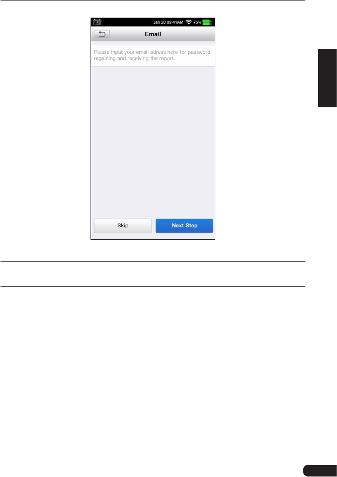
6.Afterthenetworkconnectionisdone,tap“Next”tocongureemailaddress.
Input the email address, and tap “Next” to navigate to the Job menu.
11
LAUNCH CRP 429HD User's Manual
EN
Figure 4-1
*Note: To enjoy more funcon and beer service, you are strongly recommended to
ll in the valid email address.

12
LAUNCH CRP 429HD User's Manual
4.3 Job Menu
It mainly includes the following function modules.
Diagnose TocongureCRP429HDtooperateasadiagnostictool.
HD OBD
This function provides a quick way to check for DTCs, isolate
the cause of the illuminated Malfunction Indicator Lamp
(MIL), check monitor status, verify repairs and perform a lot of
emission-related services.
Update To update vehicle diagnostic software and APK.
*Note: This function requires a stable network connection.
Data Includes Diagnostic report, Diagnostic record, Feedback and
Image etc.
Settings To make some system settings, including Network setup,
Email and Brightness etc.

13
LAUNCH CRP 429HD User's Manual
EN
5. Diagnose
5.1 Connection
1. Turn the ignition off.
2. Locate the vehicle’s DLC.
3. Select the desired adaptor cable according to your vehicle’s DLC.
• For vehicles equipped with OBD II management system, directly insert one
end of the diagnostic cable into the OBD-16 connector, and the other end to
the vehicle’s DLC.
• For vehicles equipped with non-OBD II management system, a non-16pin
adaptor cable is required. In this case, connect one end of the non-16pin
adaptor cable to the vehicle’s DLC, and the other end to the OBD-16 terminal
of the diagnostic cable. Plug the other end of the diagnostic cable into the
DB-15 connector of the handset, and tighten the captive screws.
*Note:
If the power supply on vehicle diagnosc socket is insucient or the power pin is
damaged, you can get power in the following ways:
• From cigarette lighter: insert one end of the cigarette lighter cable into the
vehicle’s lighter receptacle and connect the other end to the charging port of the
CRP 429HD.
• From battery: clamp the two clips of battery clamps cable on the positive and
negave poles of baery and insert the other end of the cable into the charging
port of the CRP 429HD.
4. Turn the ignition on. Engine can be off or running.
5.2 System Diagnosing
This function is specially designed to diagnose electronic control systems of
single vehicle model.
There are two ways available for you to diagnose vehicle systems.
5.2.1 System Scan
This module provides the ability to quickly scan the vehicle systems without
having to select the vehicle manufacturer and model step by step. After all
connections are properly made, turn the ignition key on and the system enters
automatic system scanning mode.
*CAUTION: Don’t connect or disconnect any test equipment with ignion on or engine
running.
14
LAUNCH CRP 429HD User's Manual
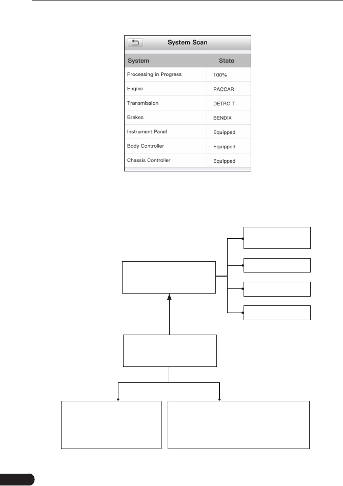
After the scanning is complete, a screen similar to the following displays.
Fig. 5-1
Tap the desired system, and then follow on-screen instructions to start a
diagnosticsession.Oncethevehiclediagnosisisnished,thesystemwilloutput
a diagnostic report. For details on manual diagnosis, see Chapter 5.2.2.
Automatic
(Note: This mode allows
your tool to scan the vehicle
test system automatically)
Manual Select
(Note: In this case, you need to choose the
desired system manually. Just follow the
on-screen instructions to proceed.)
Select test system
Select test function
Read version
information
Read fault code
Clear fault code
Read data stream
Fig. 5-2

15
LAUNCH CRP 429HD User's Manual
EN
5.2.2 Manual Diagnosis
If the system scanning failed to run, you can also perform vehicle diagnosis
manually. In this mode, you need to execute the menu-driven command and
then follow the on-screen instruction to proceed.
*Notes:
• Before diagnosing, please make sure the diagnosc program corresponding to certain
vehicle model has been installed on your CRP 429HD.
• For vehicles manufactured by different vendors, it is possible that it has different
diagnosc menus. For details, please follow the instrucons on the screen to proceed.
Refertotheowchartillustratedasbelowtodiagnoseavehiclemanually:
Select “Diagnose”
Automatic
(Note: This mode allows
your tool to scan the vehicle
test system automatically)
Manual Select
(Note: In this case, you need to choose the
desired system manually. Just follow the
on-screen instructions to proceed.)
Select test system
Select test function
Select Vehicle Model
(Note: For different vehicles,
vehicle make selection may
differ. Generally, we can
choose a vehicle via make
year. But for BENZ, we need
to choose it via chassis.)
Select Vehicle
Manufacturer
Read version
information*
Read fault code*
Clear fault code*
Read data stream*
Fig. 5-3
A. Version Information
This function is used to read the version information of system mode, vehicle
VIN, software and ECU.

16
LAUNCH CRP 429HD User's Manual
B. Read Fault Code
This function displays the detailed information of DTC records retrieved from the
vehicle’s control system.
On the Read fault code page, you can do the following:
• Tap “Code Search” to search for more information about the current DTC
online.
• Tap “Report” to save the current data in text format. All diagnostic reports
can be accessed from “Data” -> “Diagnostic Report”.
*Note: Retrieving and using DTCs for troubleshooting vehicle operation is only one
part of an overall diagnostic strategy. Never replace a part based only on the DTC
denion. Each DTC has a set of tesng procedures, instrucons and ow charts that
must be followed to confirm the location of the problem. This information can be
found in the vehicle’s service manual.
C. Clear Fault Code
After reading the retrieved codes from the vehicle and certain repairs have been
carried out, you can use this function to erase the codes from the vehicle. Before
performing this function, please be sure the vehicle’s ignition key is in the ON
position with the engine off.
*Note:
1. If you plan to take the vehicle to a Service Center for repair, DO NOT erase the codes
from the vehicle’s computer. If data is erased, valuable informaon that might help
the technician troubleshoot the problem will also be erased.
2. Clearing DTCs does not fix the problem(s) that caused the code(s) to be set. If
proper repairs to correct the problem that caused the code(s) to be set are not
made, the code(s) will appear again and the check engine light will illuminate as
soon as the problem that cause the DTC to set manifests itself.
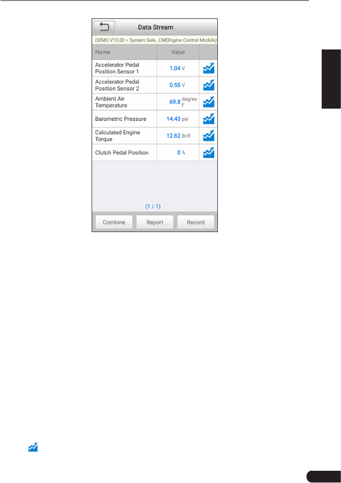
D. Read Data Stream
This option retrieves and displays live data and parameters from the vehicle’s
ECU. This data including current operating status for parameters and/or sensor
information can provide insight on overall vehicle performance. It can also be
used to guide vehicle repair.
Tap “Read Data Stream”, the system will display data stream items.
After selecting the desired items, tap “OK” to enter the data stream reading
page.
17
LAUNCH CRP 429HD User's Manual
EN
Fig. 5-4 (This screenshot is for illustrave purpose only. All data shown is cous in
nature.)
*Notes:
1. If the value of the data stream item is out of the range of the standard (reference)
value, the whole line will display in red. If it complies with the reference value, it
displays in blue (normal mode).
2. The indicator 1/X shown on the boom of the screen stands for the current page/
total page number. Swipe the screen from the right/left to advance/return to the
next/previous page.
There are 3 types of display modes available for data viewing, allowing you to
view various types of parameters in the most suitable way.
• Value – thisisthedefaultmodewhichdisplaystheparametersintextsand
shows in list format.
• Graph–displaystheparametersinwaveformgraphs.
• Combine–thisoption ismostlyusedingraphmergestatusfordata
comparison. In this case, different items are marked in different colors.
On Fig. 5-4, the following operations are available:
• Tap to view the waveform graph of the current data stream item.
18
LAUNCH CRP 429HD User's Manual
• Tap “Combine”, a pull-down list of the data stream items appears on the
screen. Select the necessary items and the screen will display the waveforms
corresponding to these items immediately.
• Tap “Report” to save the current data as a diagnostic report. All diagnostic
reports can be accessed from “Data” -> “Diagnostic Report”. CRP 429HD
logs the Date of Report (the date and time at which the report was created)
and assigns a unique Report #.
• Tap “Record” to record and save Live Data. Recorded Live Data can serve
as valuable information to help you in troubleshooting and diagnosing vehicle
problems. The saved file follows the naming rule: It begins with vehicle
type, and then the record starting time and ends with .x431 (To differentiate
between files, please configure the accurate system time). All diagnostic
records can be viewed by tapping “Data” -> “Diagnostic Record”.
5.3 HD OBD Diagnosis
This option presents a quick way to check for DTCs, isolate the cause of the
illuminated Malfunction Indicator Lamp (MIL), check monitor status prior to
emissions certification testing, verify repairs, and perform a number of other
services that are emission-related.
If a vehicle equipped with OBD II is tested, the system will enter the function
selectionscreenoncescanninghasnishedsuccessfully.SeeChapter5.3.2.
If a vehicle equipped with non-OBD II management system is diagnosed, the
system will continue scanning the protocols the vehicle supports and then enter
the system selection screen.
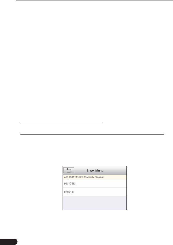
5.3.1 HD OBD Diagnosing
If scanning failure occurs, the system will enter a screen similar to the following:
Figure 5-5
Inthiscase,followthediagnosisowchartshownasbelowtoproceed:

19
LAUNCH CRP 429HD User's Manual
EN
Select “HD OBD”
Manual Select
(Note: In this case, you need to choose the
desired system manually. Just follow the
on-screen instructions to proceed.)
Automatic
(Note: This mode allows your tool to scan
the vehicle test system automatically)
Select test system
Select test function
Select system search
mode
System information
Read fault code
Clear fault code
Read data stream
Figure 5-6
1. System Information
This function is used to read the version information of system mode, vehicle
VIN, software and ECU.
2. Read diagnostic trouble code
This option is used to read the current activated or historical activated trouble
codes.
*Note: Diagnosc Trouble Codes or Fault Codes can be used to idenfy which engine
systems or components that are malfunctioning. The on-board computer records
codes of the following two types of engine problems.
• “Hard”DTCs: represent problems that are occurring now and cause the instrument
panel Malfunction Indicator Lamp (MIL) or Check Engine Light to illuminate and
remain on unl the failure is repaired.
• Intermittent/HistoryDTCs: represent problems that occur intermittently, or
happened in the past but are not currently present. Intermittent DTCs may
cause the Malfunction Indicator Lamp to flicker or stay on until the intermittent
malfunction goes away. However the corresponding fault code will be stored in
memory as a history DTC.

20
LAUNCH CRP 429HD User's Manual
Generally, there are three elements for one J1939 DTC (See Figure 5-7):
• SuspectParameterNumber(SPN)–IndicateswhatfunctionontheECUhas
failed.
• FailureModeIndicator(FMI)–Indicatesinwhatwaythefunctionfailed.
• Occurence(OC)–IndicatestheoccurencetimesofthecurrentDTC.
Whereas, if we choose [J1587/1708], the fault code includes:
• SubsystemIdentier(SID)–IndicateswhatfunctionontheECUhasfailed.
• FailureModeIndicator(FMI)–Indicatesinwhatwaythefunctionfailed.
• Occurence(OC)–IndicatestheoccurencetimesofthecurrentDTC.
*Note: Retrieving and using DTCs for troubleshooting vehicle operation is only one
part of an overall diagnostic strategy. Never replace a part based only on the DTC
denion. Each DTC has a set of tesng procedures, instrucons and ow charts that
must be followed to confirm the location of the problem. This information can be
found in the vehicle’s service manual.
3. Clear diagnostic trouble code
This option allows you to clear the existing or historic trouble codes.
ClearingDTCsdoesnotxtheproblem(s)thatcausedthecode(s)tobeset.If
proper repairs to correct the problem that caused the code(s) to be set are not
made, the code(s) will appear again and the check engine light will illuminate as
soon as the problem that cause the DTC to set manifests itself.
*Note: Aer clearing, you should retrieve trouble codes once more or turn ignion
on and retrieve codes again. If there are still some trouble codes in the system,
please troubleshoot the code using a factory diagnosis guide, then clear the code and
recheck.
4. Data stream
This option enables you to read the real-time data stream in character or graphic
form.
*Note: If you must drive the vehicle in order to perform a troubleshoong procedure,
ALWAYS have a second person help you. Trying to drive and operate the CRP 429HD at
the same me is dangerous, and could cause a serious trac accident.
5.3.2 EOBDII Diagnosing
On Fig. 5-5, tap [EOBD II] to start initializing. Once the initialization is complete,
a screen displaying Monitor Status appears. Tap [OK] to enter the function
selection page.

21
LAUNCH CRP 429HD User's Manual
EN
It mainly includes the following functions:
1. Read Codes
This option is used to read the current, pending or permanent trouble codes.
2. Erase Codes
It is used to clear all existing trouble codes.
*Notes:
• Before performing this function, make sure to retrieve and record the trouble
codes.
• After clearing, you should retrieve trouble codes once more or turn ignition on
and retrieve codes again. If there are sll some trouble codes in the system, please
troubleshoot the code using a factory diagnosis guide, then clear the code and
recheck.
3. I/M Readiness
I/M refers to Inspection and Maintenance that is legislated by the Government
to meet federal clean-air standards. I/M Readiness indicates whether or not the
various emissions-related systems on the vehicle are operating properly and are
ready for Inspection and Maintenance testing.
The purpose of the I/M Readiness Monitor Status is to indicate which of the
vehicle’s Monitors have run and completed their diagnosis and testing, and
which ones have not yet run and completed testing and diagnosis of their
designated sections of the vehicle’s emissions system.
The I/M Readiness Monitor Status function also can be used (after repair of
a fault has been performed) to confirm that the repair has been performed
correctly, and/or to check for Monitor Run Status.
Note: N/A means not available on this vehicle; INC means incomplete or not ready and
OK means Completed or Monitor Ok.
4. Data Stream
This item enables you to view all data stream items and the live waveform of all
selected items.
5. View Freeze Frame
When an emission-related fault occurs, certain vehicle conditions are recorded
by the on-board computer. This information is referred to as freeze frame data.
Freeze Data is a snapshot of the operating conditions at the time of an emission-
related fault.

22
LAUNCH CRP 429HD User's Manual
*Note: If DTCs were erased, Freeze Data may not be stored in vehicle memory
depending on vehicle.
6. O2 sensor test
The results of O2 sensor test are not live values but instead the results of the
ECU’s last O2 sensor test. For live O2 sensor readings, refer to any of the live
sensor screens such as Graph Screen.
Not all test values are applicable to all vehicles. Therefore, the list generated
will vary depending on vehicle. In addition, not all vehicles support the Oxygen
Sensors screen.
7. On-board monitor test
This function can be utilized to read the results of on-board diagnostic monitoring
testsforspeciccomponents/systems.
8. Evap System
The EVAP test function lets you initiate a leak test for the vehicle’s EVAP system.
CRP 429HD does not perform the leak test, but signals to vehicle’s on-board
computer to initiate the test. Before using the system test function, refer to the
vehicle’s service repair manual to determine the procedures necessary to stop
the test.
9. Vehicle Infomation
This option allows you to retrieve a list of information (provided by the vehicle
manufacturer), unique to the vehicle under test, from the vehicle’s on-board
computer. This information may include:
• VIN(VehicleIdenticationNumber)
• CIDs (Calibration ID) -- These CIDs uniquely identify the software version for
the vehicle’s control module.
• CVNs (Calibration Verification Number) -- CVNs are used to determine if
emission-related calibrations for the vehicle under test have been changed.
One or more CVNs may be returned by the vehicle’s on-board computer.
23
LAUNCH CRP 429HD User's Manual
EN
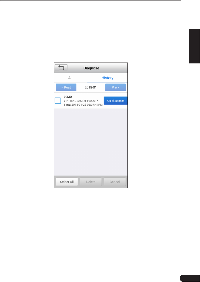
5.4 History
Generally once a vehicle diagnosis is performed, CRP 429HD will record the
every details of diagnostic session. The History function provides direct access
to the previously tested vehicles and users can resume from the last operation,
without the necessity of starting from scratch.
Tap “History” on the Manual Diagnosis main menu screen, all diagnostic records
will be listed on the screen in date sequence.
Fig. 5-7
• Tapcertainvehiclemodeltoviewthedetailsofthelastdiagnosticreport.
• Todeletecertaindiagnostichistory,selectitandthentap“Delete”.Todelete
all historical records, tap “Select All” and then tap “Delete”.
• Tap“Quickaccess”todirectlynavigatetothefunctionselectionpageoflast
diagnostic operation. Choose the desired option to proceed.

24
LAUNCH CRP 429HD User's Manual
6. Update
If some new software or APK can be updated, a numeric indicator will display on
the “Upgrade” module on the Job menu. In this case, you may use this option to
keep it synchronized with the latest version.
*Notes:
• To enjoy more funcons and beer service, you are strongly suggested to update it
on regular basis.
• This funcon requires a stable network connecon.
Tap “Upgrade” on the Job menu to enter the update center.
By default, all diagnostic software is selected.
To deselect certain software, tap “Unselect”, and then check the box next to
vehicle model.
Tap“Update”tostartdownloading.Itmaytakeseveralminutestonishit,please
be patient to wait. To pause downloading, tap “Stop”. To resume it, tap “Continue”.
If network connection failure occurs, tap “Retry” to try again.
Oncedownloadisnished,thesoftwarepackageswillbeinstalledautomatically.
25
LAUNCH CRP 429HD User's Manual
EN
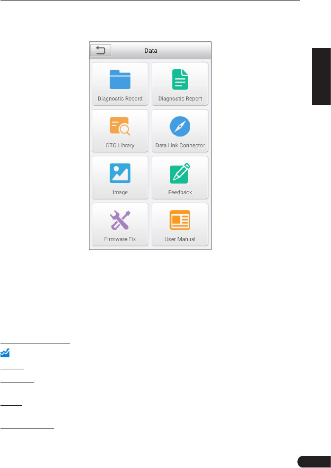
7. Data
Fig. 7-1
7.1 Diagnostic Record
If user records the running parameters or waveform graphs while reading data
stream, it will be saved as diagnostic records and appear under this tab.
Tap “Diagnostic Record” to enter, select and tap the desired data stream items
and tap “OK” to jump to the playback page.
On-screen Buttons:
: Tap it to view the waveform graph of the current data stream item.
Graph–displaystheparametersinwaveformgraphs.
Combine–thisoptionismostlyusedingraphmergestatusfordatacomparison.
In this case, different items are marked in different colors.
Value – thisisthedefaultmodewhichdisplaystheparametersintextsand
shows in list format.
Auto Playback–playsbacktherecordeddatastreamitemsautomatically.
26
LAUNCH CRP 429HD User's Manual
7.2 Diagnostic Report
This module stores all diagnostic reports generated in process of vehicle
diagnosis.
All the diagnostic reports are sorted by Date and Make. If there are too many
reports stored, tap (Search)tolterandquicklylocateit.
• To select certain report, just check the box at the lower right corner of the
report. To select all reports, tap “Select All”. To deselect all, tap “Unselect”.
• Tap it to view its details.
• Select the desired report and then tap “Delete” to delete it.
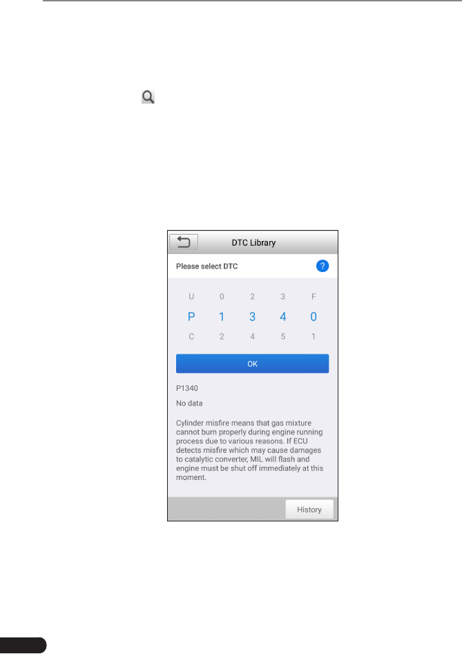
7.3 DTC Library
Thisoptionhelpsyoutondthelocationofthevehicle’sDLC.
Fig. 7-2
Swipe the screen upwards/downwards to alter the value, then press [OK] button,
thescreenwilldisplaydenitionoftheDTC.

27
LAUNCH CRP 429HD User's Manual
EN
7.4 DLC(Data Link Connector) Location
Thisoptionhelpsyoutondthelocationofthevehicle’sDLC.
7.5 Image
This option enables you to manage the screenshots.
7.6 Feedback
This item allows you to feedback your diagnostic problems to us for analysis and
troubleshooting.
Tap “Feedback”, the following 3 options will be displayed on the left column of
the screen.
A. Feedback
Tap a tested vehicle model to enter the feedback screen.
1) Tap “Choose File” to open the target folder and choose the desired diagnostic
logs.
2)Choosethefailuretypeandllinthedetailedfailuredescriptionintheblank
text box and telephone or email address. After inputting, tap “Submit Result”
to send it to us.
B. History
Tap it to view all diagnostic feedback records. Different process states are
marked with different colors.
C.Ofinelist
Tap it to display all diagnostic feedback logs which have not been submitted
successfully due to network failure. Once the handset gets a stable network
signal, it will be uploaded to the remote server automatically.
7.7 Firmware Fix
Usethisitemtoupgradeandxdiagnosticrmware.Duringxing,pleasedonot
cut power or switch to other interfaces.
7.8 User Manual
Provides a detailed description on how to operate the CRP 429HD. Before
operating the handset, please carefully read it.

28
LAUNCH CRP 429HD User's Manual
8. Settings
8.1 Units of measurement
It is designed to set the measurement unit. Metric System and English System
are available.
8.2 Automatic detection on connect
This option enables you to determine whether to start an automatic VIN detection
once CRP 429HD is properly connected to the vehicle’s DLC.
8.3 Display & Brightness
This item allows you to set the standby time and screen brightness.
*Tips: Reducing the brightness of the screen is helpful to conserve the power of the
handset.
8.4 Sound
This option lets you adjust the volume and other sound settings.
8.5 Network
*Note: Once WLAN is set as ON, CRP 429HD will consume more power. While it keeps
unused, please set it o to save power. While WLAN keeps unused, please turn it o
to conserve baery power.
CRP 429HD has built-in WLAN module that can be used to get online. Once
you’re online, you can register your tool, update diagnostic software & APK,
send email on your network.
Slide the switch to ON, the system starts searching for all available wireless
LANs. Choose the desired WLAN access point / network to connect.
8.6 Date/Time
This option allows you to set the system date & time.
*Note: Since all diagnostic reports are sorted by Make and Date. To differentiate
between les, please congure the accurate system me.

29
LAUNCH CRP 429HD User's Manual
EN
8.7 Language
CRP 429HD supports multiple languages. You can use this option to change the
target language.
8.8 Email Setup
This option is used to set up the email address for receiving the diagnostic
reports.
8.9 Recovery
Use this item to reset this tool to the default factory setting.
*Warning: Reseng may cause data loss. Before doing so, please be careful to perform
this operaon.
8.10 Version
BOOT, Download, App and System version are included.
8.11 About
This option displays the hardware configuration information of the tool and
license agreement.

30
LAUNCH CRP 429HD User's Manual
9. FAQ
Here we list some frequently asked questions and answers related to CRP
429HD.
1 System halts when reading data stream. What is the reason?
It may be caused by a slackened connector. Please turn off the tool, firmly
connect the connector, and switch it on again.
2Screenofmainunitashesatengineignitionstart.
Caused by electromagnetic disturbing, and this is normal phenomenon.
3 How to save power?
• Please turn off the screen while the handset keeps idle.
• Set a shorter standby time.
• Decrease the brightness of the screen.
• If WLAN connection is not required, please turn it off.
4 Failed to enter into vehicle ECU system?
Pleaseconrm:
• Whether the vehicle is equipped with the system.
• Whethertheidentiedsystemiselectroniccontrolsystem.
• Whether the diagnostic cable is correctly connected.
• Whether the vehicle ignition switch is On.
If all checks are normal, send vehicle year, make, model and VIN number to us
using Diagnostic Feedback feature.
5 Why are there so many fault codes?
Usually, it’s caused by poor connection or fault circuit grounding.

31
LAUNCH CRP 429HD User's Manual
EN
Warranty
THIS WARRANTY IS EXPRESSLY LIMITED TO PERSONS WHO PURCHASE
LAUNCH PRODUCTS FOR PURPOSES OF RESALE OR USE IN THE
ORDINARY COURSE OF THE BUYER’S BUSINESS.
LAUNCH electronic product is warranted against defects in materials and
workmanship for one year (12 months) from date of delivery to the user.
This warranty does not cover any part that has been abused, altered, used for a
purpose other than for which it was intended, or used in a manner inconsistent
with instructions regarding use. The exclusive remedy for any automotive meter
found to be defective is repair or replacement, and LAUNCH shall not be liable
for any consequential or incidental damages.
Final determination of defects shall be made by LAUNCH in accordance with
procedures established by LAUNCH. No agent, employee, or representative of
LAUNCHhasanyauthoritytobindLAUNCHtoanyafrmation,representation,
or warranty concerning LAUNCH automotive meters, except as stated herein.
Order Information
Replaceable and optional parts can be ordered directly from your LAUNCH
authorized tool supplier. Your order should include the following information:
1. Quantity
2. Part number
3. Item description
Customer Service
If you have any questions on the operation of the unit, please contact local
dealer, or contact LAUNCH TECH. CO., LTD:
Tel: 86-755-84528767
E-mail: X431@cnlaunch.com
Statement: LAUNCH reserves the rights to make any change to this manual without
notice. We have tried our best to make the descriptions and illustrations in the manual as
accurate as possible, and defects are inevitable, if you have any question, please contact
local dealer or LAUNCH Tech(USA), Inc., LAUNCH does not bear any responsibility
arising from misunderstandings.
Emergency call
If any emergency arises, dial 112/911 (or other emergency call number) for
emergency help.
Due to the nature of cellular networking, the success of emergency call is not
guaranteed.
FCC Warning:
This device complies with part 15 of the FCC Rules. Operation is subject to the
following two conditions: (1) This device may not cause harmful interference,
and (2) this device must accept any interference received, including
interference that may cause undesired operation.
Any Changes or modifications not expressly approved by the party responsible
for compliance could void the user's authority to operate the equipment.
This equipment has been tested and found to comply with the limits for a Class
B digital device, pursuant to part 15 of the FCC Rules. These limits are
designed to provide reasonable protection against harmful interference in a
residential installation. This equipment generates uses and can radiate radio
frequency energy and, if not installed and used in accordance with the
instructions, may cause harmful interference to radio communications.
However, there is no guarantee that interference will not occur in a particular
installation. If this equipment does cause harmful interference to radio or
television reception, which can be determined by turning the equipment off and
on, the user is encouraged to try to correct the interference by one or more of
the following measures:
-Reorient or relocate the receiving antenna.
-Increase the separation between the equipment and receiver.
-Connect the equipment into an outlet on a circuit different from that to which
the receiver is connected.
-Consult the dealer or an experienced radio/TV technician for help.
The SAR limit of USA (FCC) is 1.6 W/kg averaged over one gram of tissue.
Device types Element PLUS (FCC ID: XUJCRP429HD) has also been tested
against this SAR limit. The highest reported SAR values for body-worn
accessory. The Max simultaneous SAR is 0.68 W/kg. This device was tested
for typical body-worn operations with the back of the handset kept 0mm from
the body. To maintain compliance with FCC RF exposure requirements, use
accessories that maintain a 0mm separation distance between the user's body
and the back of the handset. The use of belt clips, holsters and similar
accessories should not contain metallic components in its assembly. The use
of accessories that do not satisfy these requirements may not comply with
FCC RF exposure requirements, and should be avoided.