Launch Tech DS601 Automotive Diagnosis Terminal User Manual Maximus 3 0 English R indd
Launch Tech Co., Ltd. Automotive Diagnosis Terminal Maximus 3 0 English R indd
UserManual.wiki
>
Launch Tech
>
DS601 User Manual
Users Manual
Navigation menu
Upload a User Manual
Namespaces
Wiki Guide
HTML
PDF
Info
Views
User Manual
Discussion / Help
Navigation
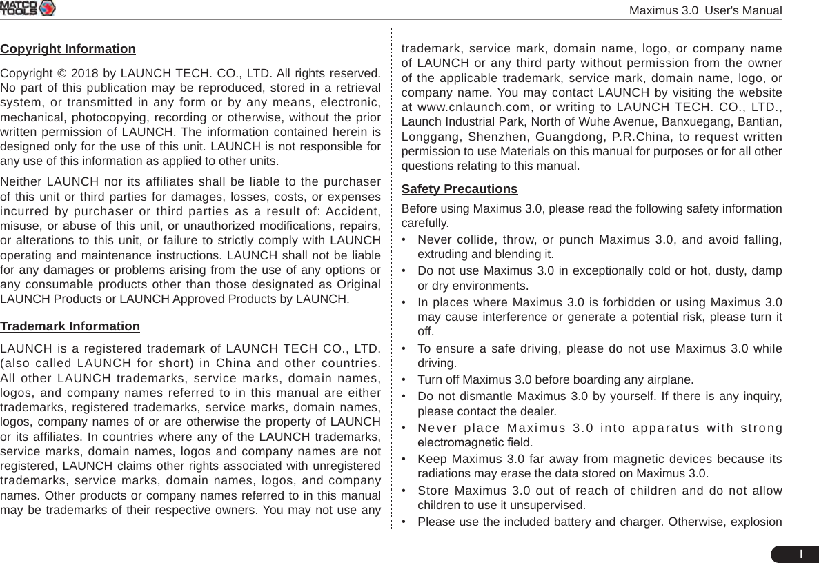
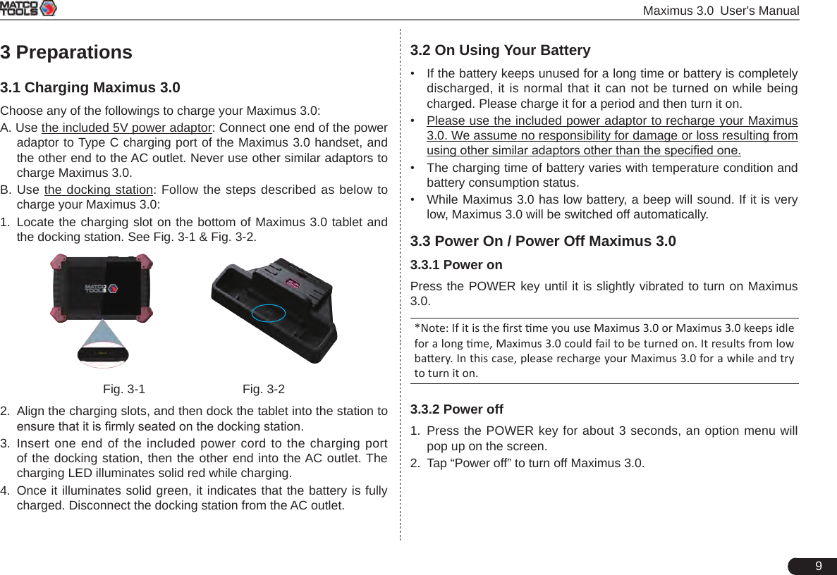
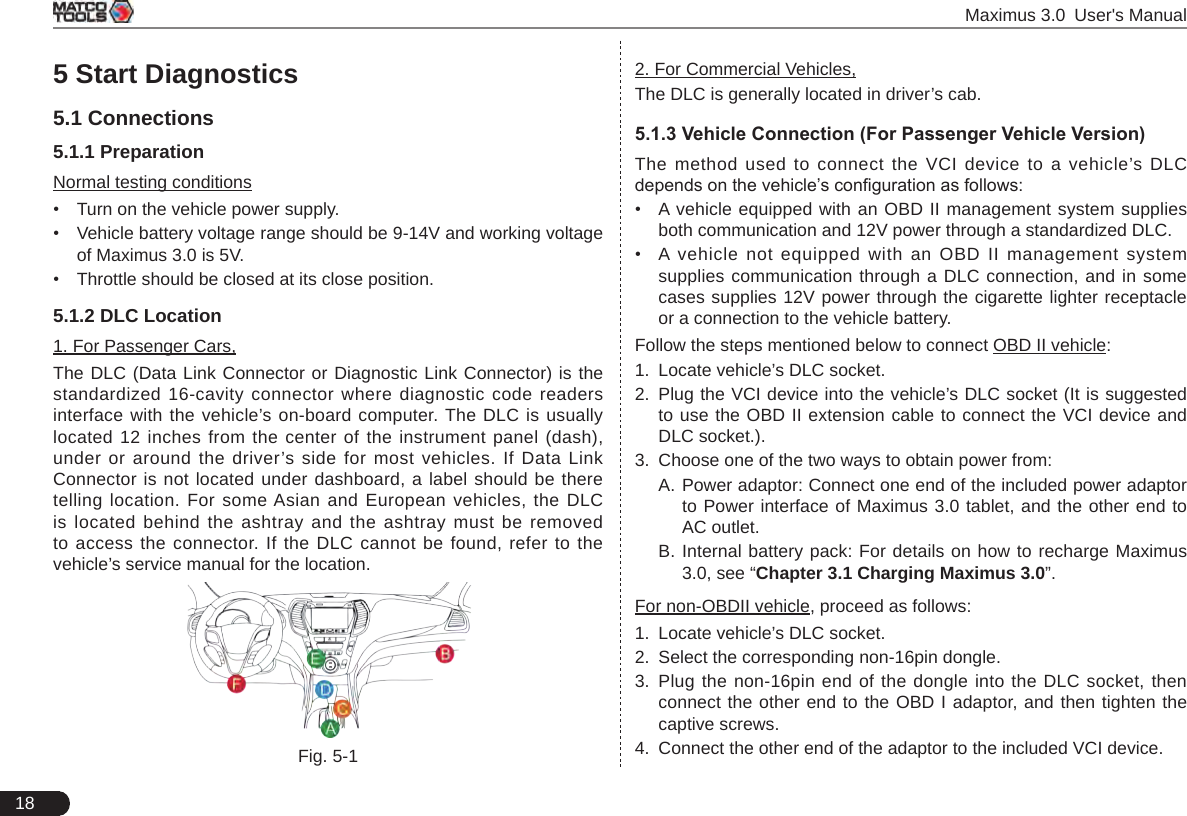
![4 Maximus 3.0 User's Manual2.1 Maximus 3.0 Tablet Fig. 2-4 Maximus 3.0 Tablet (front & side view)Table 2-1 formulates ports and indicators of Maximus 3.0 tablet:No. Name & Descriptions1Memory Card Slot -- To store the memory card for storage expansion.2Type C Charging Port -- Reserved for charging the Maximus 3.0 tablet.3Power/Screen Lock Button -- To turn the tablet on/off with long press, or lock the screen with short press.4Volume Buttons -- To adjust the volume. *Note: Press and hold [POWER] and [VOL -] key to capture the current screenshot.5Data Transmission Port -- Reserved for add-on modules (such as Batterybox, Scopebox, Sensorbox and Videoscope), and other devices with similar port.6Microphone7Charging indicator -- It illuminates red while Maximus 3.0 tablet is charging. Once charging is nished, it will illuminate solid green.810.1" Capacitive Touch Screen9Ambient Light Sensor10 Front Camera](https://usermanual.wiki/Launch-Tech/DS601/User-Guide-4039375-Page-10.png)
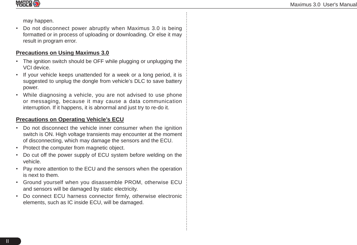
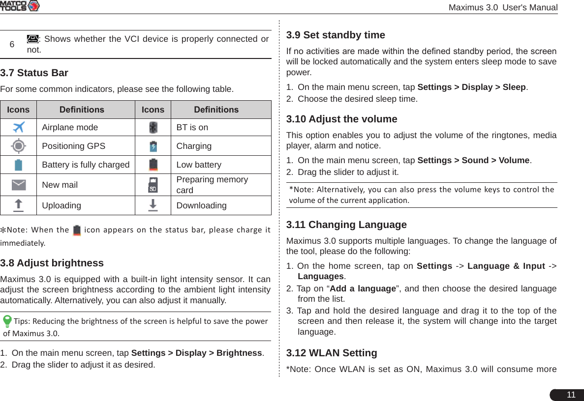
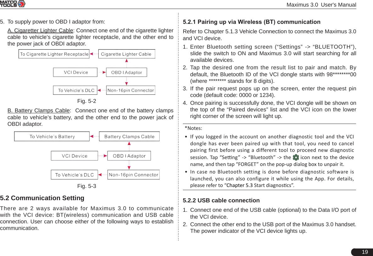
![10 Maximus 3.0 User's Manual3.4 Tips On Finger OperationsActions ResultsSingle-tap To select a item or launch a program.Double-tap To zoom in so that the text on a webpage appears in a column that ts your device’s screen. Long press Press and hold on the current interface or area until a contextual menu pops up on the screen, and then release it. Slide To jump to different pages.Drag Tap the desktop icon and drop it to other location. Spread apart / Pinch togetherTo zoom in manually, place two fingers on the screen and then spread them apart. To zoom out, place two fingers apart on the screen and then pinch them together.3.5 Lock & unlock the screenMany screen lock modes are available on Maximus 3.0. Take the preset screen-lock mode as example for demonstration.3.5.1 Lock the screen• When Maximus 3.0 is ON, press [POWER] key once to lock the screen; • The system will lock the screen automatically after Maximus 3.0 remains idle over the preset standby time. 3.5.2 Unlock the screenPress [POWER] key to activate the screen, and then drag the lock to “Unlock” position.*Notes: 1. In case you forgot the screen lock, please refer to Appendix - FAQ for details. You are not suggested to use the screen lock.2. If you use “unlock the pattern”, you have to draw the right target paern to unlock it. 3.6 Locator & Navigation Buttons1234 5 6Fig. 3-3On-screen keys and status bar are as follows: 1Tap to return to the previous screen or exit the application.2 Tap to navigate to the Android System’s home screen. 3Tap to display a list of applications that are currently running or recently used. To open an application, tap it. To remove an application, swipe it upwards. 4Tap to capture the current screen and all captured screenshots are stored in the Screenshots folder.5: Once some upgradable diagnostic software are detected, the icon will turn highlighted.](https://usermanual.wiki/Launch-Tech/DS601/User-Guide-4039375-Page-16.png)
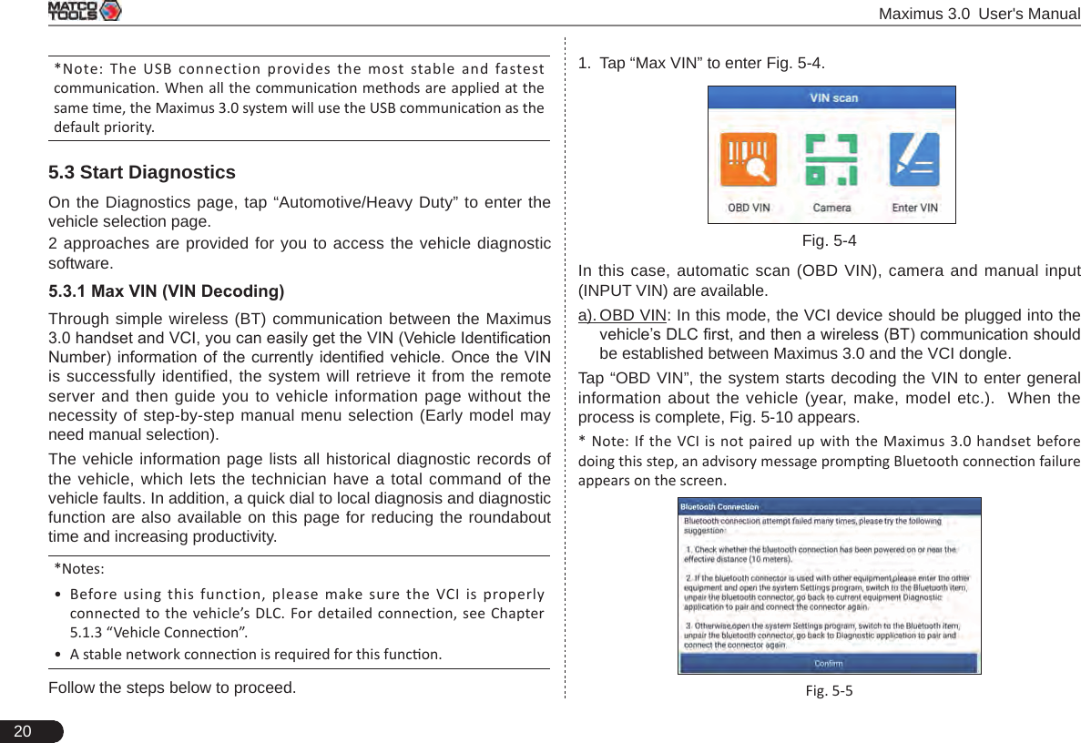
![36 Maximus 3.0 User's Manual5.6 I/M ReadinessAn important part of a vehicle’s OBD II system is the Readiness Monitors, which are indicators used to nd out if all of the emissions components have been evaluated by the OBD II system. They are running periodic tests on specic systems and components to ensure that they are performing within allowable limits.Currently, there are eleven OBD II Readiness Monitors (or I/M Monitors) defined by the U.S. Environmental Protection Agency (EPA). Not all monitors are supported in every vehicles and the exact number of monitors in any vehicle depends on the motor vehicle manufacturer’s emissions control strategy.Continuous Monitors -- Some of the vehicle components or systems are continuously tested by the vehicle’s OBD II system, while others are tested only under specific vehicle operating conditions. The continuously monitored components listed below are always ready:1. Misre2. Fuel System3. Comprehensive Components (CCM)Once the vehicle is running, the OBD II system is continuously checking the above components, monitoring key engine sensors, watching for engine misre, and monitoring fuel demands. Non-Continuous Monitors -- Unlike the continuous monitors, many emissions and engine system components require the vehicle to be operated under specic conditions before the monitor is ready. These monitors are termed non-continuous monitors and are listed below:1) EGR System2) O2 Sensors3) Catalyst4) Evaporative System5) O2 Sensor Heater6) Secondary air Injection7) Heated Catalyst8) A/C systemI/M refers to Inspection and Maintenance that is legislated by the Government to meet federal clean-air standards. I/M Readiness indicates whether or not the various emissions-related systems on the vehicle are operating properly and are ready for Inspection and Maintenance testing.The purpose of the I/M Readiness Monitor Status is to indicate which of the vehicle’s Monitors have run and completed their diagnosis and testing, and which ones have not yet run and completed testing and diagnosis of their designated sections of the vehicle’s emissions system.The I/M Readiness Monitor Status function also can be used (after repair of a fault has been performed) to confirm that the repair has been performed correctly, and/or to check for Monitor Run Status.Tap [I/M Readiness] on the Diagnostics main menu screen to start checking. After checking all I/M readiness status, the screen will output the result.*Note: means not available on this vehicle, means incomplete or not ready, means Completed or Monitor Ok.](https://usermanual.wiki/Launch-Tech/DS601/User-Guide-4039375-Page-42.png)
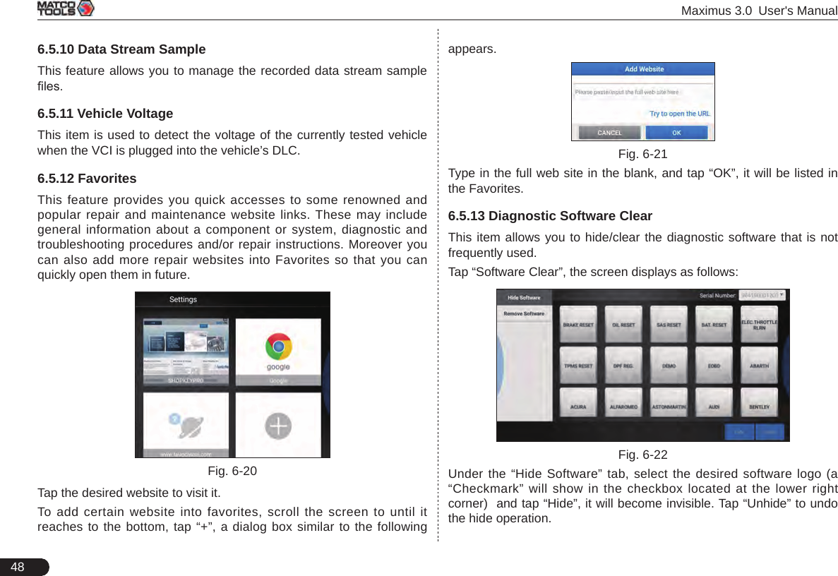
![Maximus 3.0 User's Manual47hold [MODE] & [FEED] for 8 seconds, the following resetting command will be printed out:at + default = 1okat + reboot = 1rebooting...3. Tap “Reset” to congure Wi-Fi printer.Step 1: Connect the printer: Tap “Scan” to select the desired printer hotspot named with X-431PRINTER-XXXX (XXXX stands for 4 characters), and then tap “Connect” to enter Step 2.Step 2: Join the printer into LAN: Tap “Scan” to select the desired local Wi-Fi network from the list, and type in the security password (If it is an open network, password is not required), and then tap “Conrm”.Fig. 6-184. Once the Wi-Fi network of the printer is connected and the printer is found, tap “Test Print” to test the printing.Now you can use the Wi-Fi printer to print!If the printer is not found, please reset the printer to default factory settings (refer to Step 2 for details) and check whether the current device and the printer are on the same LAN.B. If you have congured the Wi-Fi printer to the LAN:2. Tap “Connect to Printer”: a). If the local network remains as it is, tap “Test Print” directly to test the printing. b). If the local network changes, you have to reboot and recongure the Wi-Fi printer.6.5.9 Print InformationThis option lets you define your print information. It mainly includes Workshop, Address, Zip Code, Telephone, Email etc. Fig. 6-19After inputting, tap “Save”. Once you saved the print information, it will be loaded automatically in the “More Information” box every time you save the diagnostic report.](https://usermanual.wiki/Launch-Tech/DS601/User-Guide-4039375-Page-53.png)
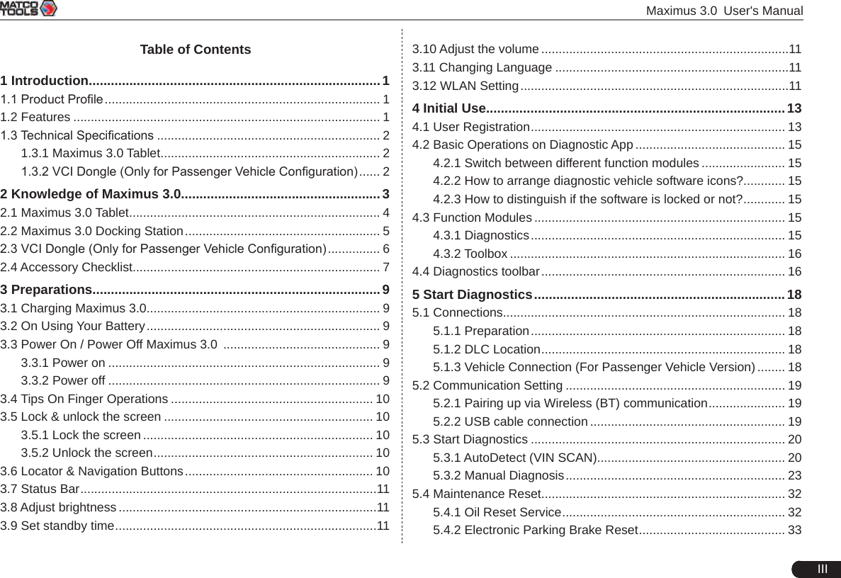
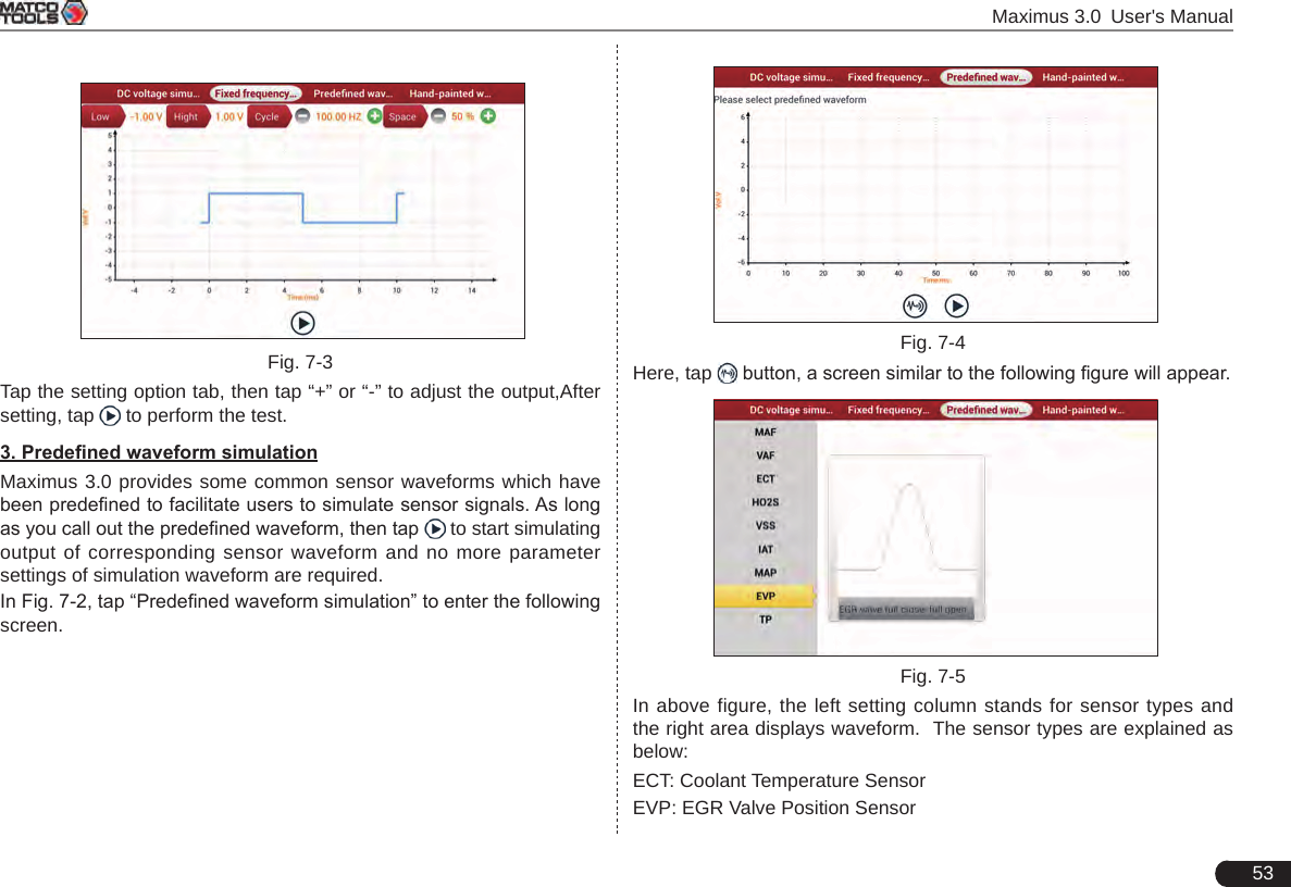
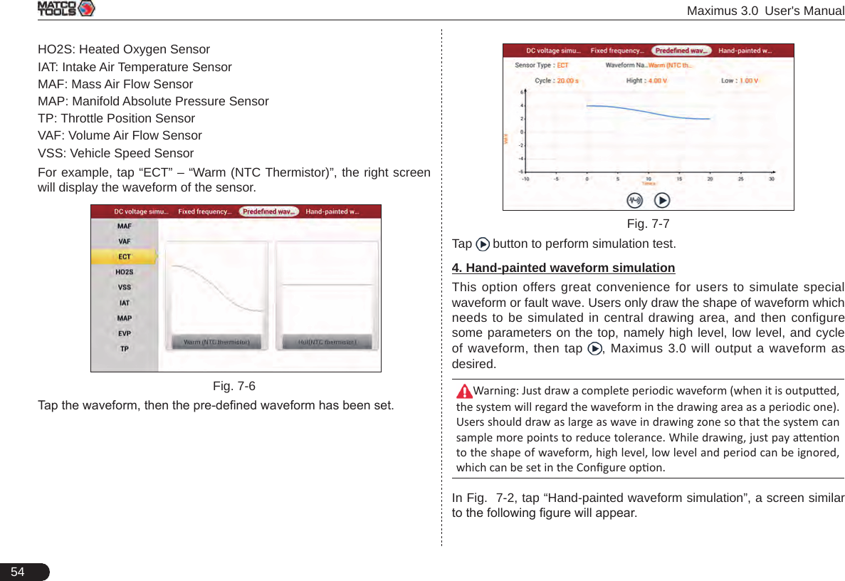
![52 Maximus 3.0 User's Manual7.1.3 Sensor Simulation7.1.3.1 Connections1. Firstly, power on the Maximus 3.0 handset.1. Connect the B-shaped terminal of data cable to the B-shaped port of the Sensorbox, and the other end to the Data transmission port of the Maximus 3.0 handset.2. Plug one end of the sensor test cable (black) into the “COM” interface of the sensorbox, then connect the other end to the test probe or electronic control converting cable.3. Connect one end of the sensor test cable (red) into the “VΩHz” interface of the sensorbox, and then connect the other end to the test probe or electronic control converting cable.*Note: Choose corresponding cables and test probes according to dierent terminals.7.1.3.2 Simulation testSimulation test enables users to exactly judge if the sensor is good or not to avoid replacing components blindly. For example, the trouble code indicates the fault is in water temperature sensor itself. But we need to confirm whether the fault results from water temperature sensor or the connections between ECU and sensors, or ECU itself. In this case, we can make full use of simulation test to input the signal of simulating water temperature sensor, instead of water temperature sensor, to the microcomputer. If the engine works better and the fault vanishes, the fault is in the water temperature sensor. If the fault still occurs, input the signal to the corresponding terminals of ECU. Consequently, if the fault disappears, the fault lies in the connection between water temperature sensor and ECU, otherwise, the fault exists in ECU.After all connections are properly made, power on your Maximus 3.0, launch Maximus 3.0 application and enter the function menu interface, then tap “Sensor” to enter the test selection screen. Fig. 7-21. DC voltage simulationIn Fig. 7-2, tap [Current voltage], then tap “+” or “-” to adjust the output voltage value. Alternatively, user can also tap edit box, then use the on-screen keyboard to input the desired value directly. After selecting or inputting the desired voltage based on the working characteristics of sensor, tap the button, then the Maximus 3.0 will begin to output the simulation voltages. Please note the red probe is the output terminal of simulation voltage.2. Fixed frequency simulationThis option enables you to simulate the square wave signal of pulse frequency of 0.1 ~ 15 kHz, amplitude range of -5V ~ +5 V and duty cycle 10% ~ 90%.In Fig. 7-2, tap “Fixed frequency simulation” to enter a screen similar to the following gure.](https://usermanual.wiki/Launch-Tech/DS601/User-Guide-4039375-Page-58.png)
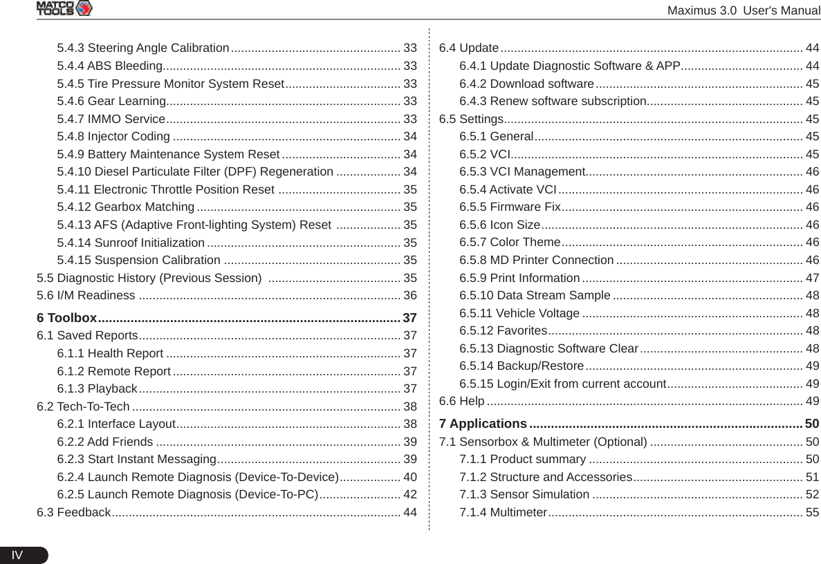
![Maximus 3.0 User's Manual55 Fig. 7-8Button descriptions:[]: Save the current waveform.[]: Loads the previously saved hand-drawn waveform.[]: Clear all hand-drawn waveform.[]: Tap to call out the predened waveform for reference. []: Continues the following operation.7.1.3.3 Precautions on checking vehicle sensor • Hold the connector when plugging or unplugging it. Do not pull the cable for unplugging.• At rst check the fuse, fusible line and terminals. Then check others after eliminating these faults.• When measuring voltage, the ignition switch should be on and the battery voltage should not be less than 11V.• When measuring voltage, please shake the lead lightly in the vertical and horizontal direction for more precision.• When checking whether there is open in the line, disconnect the CEU and the relevant sensor at rst, then measure the resistance among the ports of sensor in order to determine whether open-circuit / contact fault exists or not.• When checking if there is a short in the line, please disconnect the CEU and the relevant sensor, then measure the resistance value of the ports between the connected port and the vehicle body. If the resistance value is more than 1MΩ, no fault occurs.• Before disassembling the engine electrical control system cable, cut off the power supply, that is, turn the ignition switch OFF and disconnect the cables on the battery poles. • Contact the test probe and the two terminals/ the two leads to be measured when measuring the voltage between the two terminals or the two leads.• Contact the red test probe to the terminal/ the cable to be measured, and the black probe to the ground when measuring voltage of one terminal/ one cable.• When checking the continuity of the terminals, contacts and leads, the method for measuring their resistances can be used.• Check the faults in the terminals of the CEU to sensors, relays, etc.• There are two test probes in the testing wire. The black one is the common signal terminal (signal GND); the red one is the input terminal for voltage, resistance, and frequency test and output terminal for simulation voltage, simulation frequency and oxygen sensor. Please choose the correct probes to match the different terminals. 7.1.4 Multimeter7.1.4.1 OperationsMake sure Maximus 3.0 main unit and the sensorbox are properly connected, power on Maximus 3.0 and enter the Applications menu interface, tap “Multimeter” to display the test menu.](https://usermanual.wiki/Launch-Tech/DS601/User-Guide-4039375-Page-61.png)
![56 Maximus 3.0 User's ManualFig. 7-9Click the desired test as shown above to perform related test. The operation method on Resistance test and Frequency test is identical to that of Voltage test. Here just take Voltage test as an example for demonstration.Fig. 7-10The following operations can be done:[]: Erases the currently displayed waveform and display it starting from the left.[]: Reduces the range and zoom in the waveform.[]: Increase the range and zoom out the waveform.[]: Starts or stops the testing process.7.1.4.2 Test sampleKnock sensor testing(1) Resistance test for knock sensorSwitch ignition “OFF”, unplug the wire connector of knock sensor, test the resistance between the wire terminal and the case of knock sensor with “Resistance test” function, it shall be ∞(disconnected), and if it is 0Ω(conductive), which means the knock sensor shall be replaced. For the magnetostriction knock sensor, it can also test the resistance by the “Resistance measurement” function; the resistance shall be compliant with the specied value (see specic service manual for the detailed data), otherwise, the knock sensor shall be replaced.(2) Checking for the output signal of knock sensorUnplug the wire connector of knock sensor, check voltage between knock sensor connector terminal and ground wire of knock, it should be output pulse voltage; otherwise, the knock sensor shall be replaced.Coolant temperature sensor testing(1) Resistance test for coolant temperature sensorOn vehicle testing:Switch ignition “OFF” and unplug the wire connector of coolant temperature sensor, then use the “Resistance measurement” to test the Resistance between two terminals of sensor. The relationship between the resistance and the temperature is in inversely proportion (negative temperature coefcient), which shall be less than 1kΩ during warming up.](https://usermanual.wiki/Launch-Tech/DS601/User-Guide-4039375-Page-62.png)
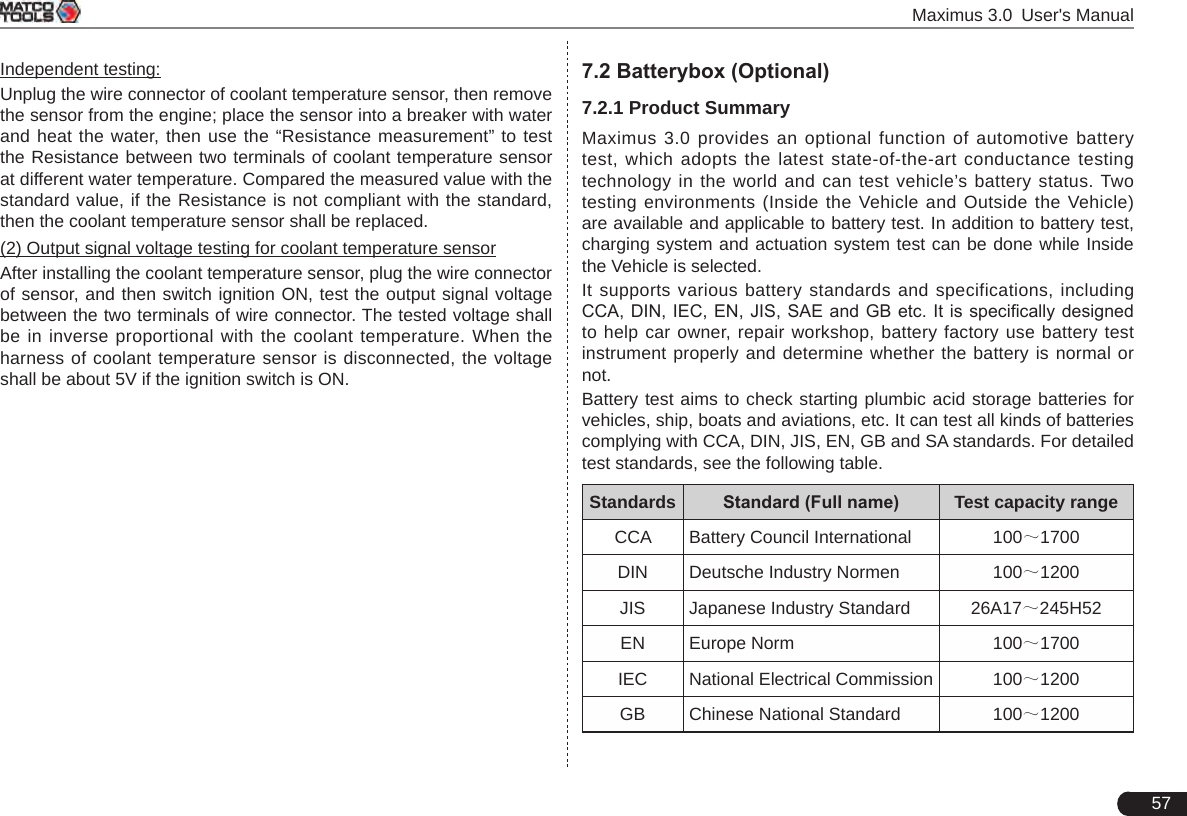
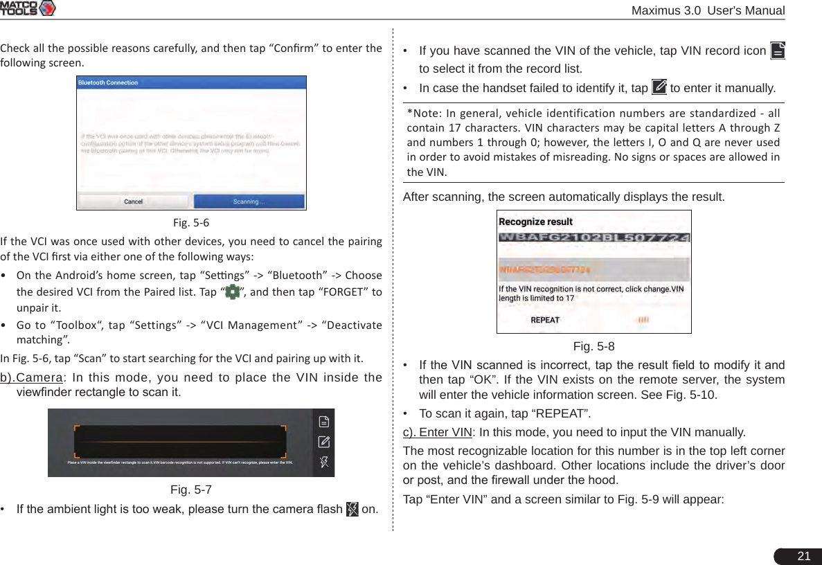
![Maximus 3.0 User's Manual597.2.3.2 Test accessoriesFig. 7-12 Kelvin clipFig. 7-13 A/B cable7.2.4 Connections & Operations7.2.4.1 ConnectionConnect one end of the A/B cable to the Type B terminal of the batterybox, and then connect the other end to the Data transmission port of Maximus 3.0 tablet. This connection applies to outside the vehicle test and inside the vehicle.*Notes:1. Wait about 10s and begin to communicate since the baerybox needs to inialize aer connecon is complete, otherwise, communicaon may fail.2. Red lamp on the batterybox means it has been successfully powered up. If the green light is always on, it indicates the clip is well connected; while the green light blinks, it indicates that the clip has poor contact. Do not perform any test unl the clip and A/B cable are properly connected.7.2.4.2 Inside the vehicle testBattery test and charging system & actuation system test can be done in this mode.1. Battery testEnter the battery test main menu screen, and select a desired test environment. Fig. 7-14*Note: The sequences of inside the vehicle and outside the vehicle test are almost the same, but under inside the vehicle condion, all loads in vehicles must be powered o for geng an exact test value.1. Firstly, the system detects whether oating electricity exists or not before testing. If yes, turn on the headlamp to remove it. Otherwise, the system starts test program directly.2. Tap [Inside the vehicle], the system starts detecting floating electricity automatically. If floating electricity is detected, it will prompt you to turn on the headlamp.3. Follow the on-screen instructions to turn on headlamp, the system starts removing oating electricity.4. Once the oating electricity is removed, a prompt message box “The oating electricity has been removed, please turn off the headlamp to continue the testing” will appear on the screen.5. Follow the on-screen instructions to turn off the headlamp and](https://usermanual.wiki/Launch-Tech/DS601/User-Guide-4039375-Page-65.png)
![60 Maximus 3.0 User's Manualtap [OK], the system will continue the testing. Tap , it will enter testing standard selection screen. Fig. 7-156. Select a testing standard except for JIS and tap to enter the following gure. Users can adjust capacity size by tapping on < or > or by dragging the slider on the bar.Fig. 7-16If JIS is selected, tap , the system will enter Select testing capacity screen. Users can select corresponding standard capacity value according to battery model marked on battery. 7. Tap and the testing result will appear on the following screen.Fig. 7-17[ ]: Tap it to perform the charging system and starting system test.[]: Tap to test it again.[]: Tap it to reset the test.2. Charging system and starting system testWhile performing this test, the battery’s charging voltage value and starting voltage can be obtained in case of engine starting and accelerating. Based on the data, the system will judge whether battery’s charging and actuation status is normal or not. Tap in Fig. 7-17, a dialog box will pop up. Fig. 7-18](https://usermanual.wiki/Launch-Tech/DS601/User-Guide-4039375-Page-66.png)
![Maximus 3.0 User's Manual61After detecting engine starting, follow the instructions on the screen to increase the speed. The system begins to receive test data information after acceleration was detected. Fig. 7-19Tap [OK], test data will be shown on the screen.*Note: It is unnecessary to perform charging system and start system test after finishing battery test, but battery test must be done before undergoing charging system and starng system test.7.2.4.3 Outside the vehicle testIt only applies to battery test and detecting oating electricity will be ignored while performing battery test. In Fig. 7-14, tap [Outside the vehicle] to select battery test standard. The following operation steps are identical to Steps 6 ~ 7 in Chapter 7.2.4.2 Battery test. Please refer to it for details. 7.2.5 Precautions on battery test For the purpose of getting accurate test results, unless otherwise special required, all loads need to be power off such as headlamp, engine etc. before testing battery.The operating time required for charging system and actuation system test varies from person to person. If the engine does not start or accelerate within 30 seconds, the system will prompt you “receiving timeout” and return to the initial status.Whether Engine is off or not has no influence on charging and actuation test result after increased speed is detected, but other loads need to be powered off.The accuracy of battery voltage, charging voltage, start voltage is 0.01V in test results; CCA (Cold Cranking Amps) precision is 5CCA. Generally, charging voltage value is greater than starting voltage. Charging voltage range is as follows: 13.8--14.5V for domestic vehicle; 13.3--15.5V for imported vehicles. The voltage varies with different car models, so you have to judge based on related vehicle models. In general, the DC voltage is stable, but it also varies with different revolution speed.Starting voltage range: The value higher than 9.6V is regular, otherwise it is too low. Due to different situations, whether the starting voltage is higher or not does not mean the vehicles or batteries are faulty. For detailed faults, other special equipments are needed. To validate the accuracy of the value, the best method is to collect the signals of starting and charging voltage and observe it on an oscillometer.Generally, the voltage is lower than 11V for the bad cell battery, but it is possible that the battery is completely exhausted or has a serious low capacity. In this case, just recharge your battery. Bad cell always happens when the loads on a stopping vehicle are turned on for a long time. Please note that it is normal for quick detecting of “Increase speed” because it follows the theory of detecting “Increase speed”: If the detected voltage is higher than the previous battery test voltage, the system will prompt you a message of “Engine has been speeded” It has no influence on test result in the event that engine’s output voltage or engine revolution is not very stable. No matter whether the vehicle is accelerated or not, the output voltage only differs within 0.2V.While doing inside the vehicle test, Kelvin clip is always found to be in poor contact. To remain it in good contact, please shake it several](https://usermanual.wiki/Launch-Tech/DS601/User-Guide-4039375-Page-67.png)
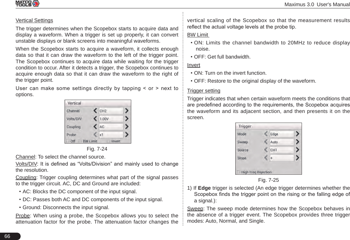
![Maximus 3.0 User's Manual656 Function Menu[Auto]: It indicates auto trigger setting. [Ref]: There are expert reference and base reference available. Expert reference enables you to recall your customized expert database, whereas base reference provides automatic pre-setting function of specialized sensors.[File]: Provides save snapshot, snapshot manager, waveform record and waveform replay.[View]: Calibration and display settings are available.[Measure]: Includes signal source measurement, horizontal measurement, vertical measurement and clear measurement. [Settings]: Shows/hides the parameter settings area including horizontal settings, vertical settings and trigger settings. / [Start/Stop]: Starts/stops collecting waveforms.7.3.4 Operations7.3.4.1 Channel selection and attributes setting<1> Channel selectionThere are two ways available for channel selection: A. Select from the channel tab shown at the bottom of the waveform display areaB. Select from Vertical settings*Note: For better comparison and identification, each channel and waveform are marked in dierent colors.Fig. 7-22<2> Channel attributes & trigger settingChannel attributes can be set via horizontal settings and vertical settings.Horizontal SettingsUser can make some settings directly by tapping < or > next to options. Fig. 7-23Time/DIV: Horizontal scale. If the waveform acquisition is stopped (using the / button), the Time/DIV selector expands or compresses the waveform.Y-T format: The conventional oscilloscope display format. It shows the voltage of a waveform record (on the vertical axis) as it varies over time (on the horizontal axis).](https://usermanual.wiki/Launch-Tech/DS601/User-Guide-4039375-Page-71.png)
![Maximus 3.0 User's Manual67• Auto: It allows the Scopebox to acquire waveforms even when it does not detect a trigger condition. If no trigger condition occurs while the Scopebox is waiting for a specic period, it will force itself to trigger.When forcing invalid triggers, the Scopebox can not synchronize the waveform, and then waveform seems to roll across the display. If valid triggers occur, the display becomes stable on the screen.• Normal: This mode allows the Scopebox to acquire a waveform only when it is triggered. If no trigger occurs, the Scopebox keeps waiting, and the previous waveform, if any, will remain on the display. • Single: In this mode, it only acquires the waveform that generates for the rst time the trigger conditions are met, and then stops after nishing capture. Source: Select which channel as trigger signal.Slope:• + : Trigger on rising edge• - : Trigger on falling edgeHigh Freq Rejection: Reject high frequency signals when selected.2) If Pulse Width trigger is selected (Pulse trigger occurs according to the width of pulse. The abnormal signals can be detected through setting up the pulse width condition):Sweep: The sweep mode determines how the Scopebox behaves in the absence of a trigger event. The Scopebox provides three trigger modes: Auto, Normal, and Single.• Auto: It allows the Scopebox to acquire waveforms even when it does not detect a trigger condition. If no trigger condition occurs while the Scopebox is waiting for a specic period, it will force itself to trigger.When forcing invalid triggers, the Scopebox can not synchronize the waveform, and then waveform seems to roll across the display. If valid triggers occur, the display becomes stable on the screen.• Normal: This mode allows the Scopebox to acquire a waveform only when it is triggered. If no trigger occurs, the Scopebox keeps waiting, and the previous waveform, if any, will remain on the display. • Single: In this mode, it only acquires the waveform that generates for the rst time the trigger conditions are met, and then stops after nishing capture.Source: Select which channel as trigger signal.Condition: To select pulse condition. Pulse Width: Set required pulse width.High Freq Rejection: Reject high frequency signals when selected.7.3.4.2 AutoThe Scopebox has an Auto feature that sets up the Scopebox automatically to display the input signal in a best t. Tap , the Scopebox may change the current settings to display the signal. It automatically adjusts the vertical and horizontal scaling, as well as the trigger coupling, position, slope, level and mode settings.7.3.4.3 View Settings<1> CalibrationThis option adjusts the Scopebox’s internal circuitry to get the best accuracy. Use this function to calibrate the Scopebox’s vertical and horizontal systems.Tap and then tap [Calibration], a dialog box similar to Fig. 7-26 will appear.](https://usermanual.wiki/Launch-Tech/DS601/User-Guide-4039375-Page-73.png)
![68 Maximus 3.0 User's Manual Fig. 7-26Check the box before the channel to select it. To deselect it, just uncheck it. After choosing the desired channel(s), tap [Start] to start calibration and [Start] button will be temporarily invalid during calibrating. Tap [Stop] to stop calibrating. Once it becomes active, it indicates calibration has completed. *Note: In process of calibration, make sure CH1/CH2/CH3/CH4 has no signal input. Moreover, calibraon may take several minutes and please be paent to wait.<2> REF settingsReference waveforms are saved waveforms to be selected for display. The reference function will be available after saving the selected waveform to non-volatile memory.Tap and then [REF] to enter the REF setting screen. Fig. 7-27Tap < or > to select the desired reference value for time/DIV and volts/DIV. To show or hide the REF, just check/uncheck the box before On/Off.<3> Display settingsTap and then [Display settings] to enter the setting screen. Fig. 7-28Select “Vectors” or “Dots” to display waveforms as vectors or dots. Check / uncheck the box before Grid to turn on/off grid display.7.3.4.4 Measure<1> Channel sourceTap and then [Source], a screen similar to the following will appear.](https://usermanual.wiki/Launch-Tech/DS601/User-Guide-4039375-Page-74.png)
![Maximus 3.0 User's Manual69 Fig. 7-29<2> Horizontal / Vertical measureHorizontal Measure / Vertical Measure are used to measure voltage parameter and time parameter respectively. Drag A line upwards or downwards to control voltage. Move A line left or right to fine-tune timebase. A line is a solid line and B line is a dotted line.Tap and then [Horizontal Measure], a screen similar to the following will appear.Fig. 7-30* Note: If no desired channel is selected, the system will take the current source as the default channel.<3> Clear measureTap and then [Clear Measure], the system will clear the measurement result on screen.7.3.4.5 File management<1> Save snapshotWhile viewing sampling data, tap and then [Save Snapshot] to store the current screen.<2> Snapshot managerWhile viewing sampling data, tap and then [Snapshot Manager] to enter. View, delete and edit operations are supported.<3> Record waveformThis function is used to record input waveforms that are acquired by the Scopebox at a specic period, and save it as waveform le which can be recalled in future.It can be performed only when the Scopebox is collecting data in Normal mode. Tap , then select [Record] from the pop-up menu to start recording. Fig. 7-31](https://usermanual.wiki/Launch-Tech/DS601/User-Guide-4039375-Page-75.png)
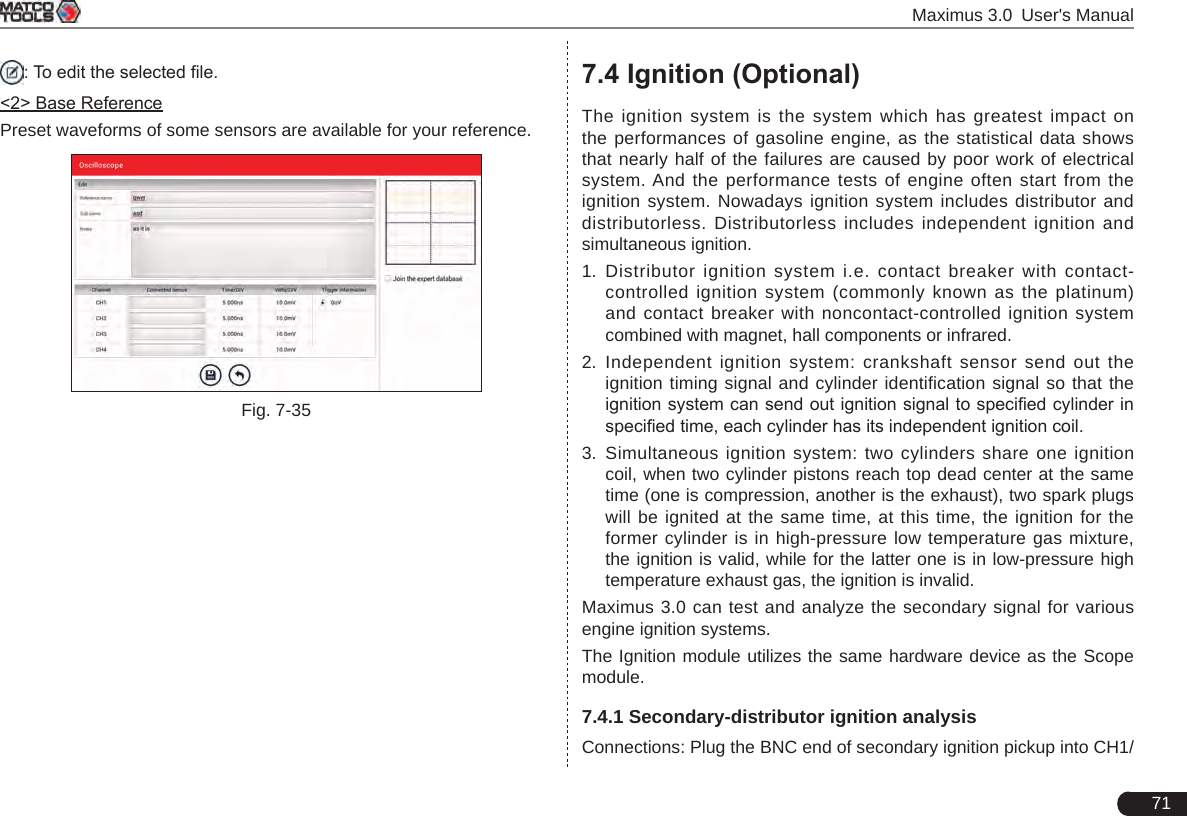
![70 Maximus 3.0 User's ManualTap [Start] to start recording with a minimum record length of 10 frames, and [Stop] to stop recording. While recording, the recorded pages will be shown on the screen.<4> Load waveform for playbackThe Import function enables you to import the stored waveform le for playback and review. During replaying, the Scopebox stops collecting data automatically. Tap , then select [Waveform replay] from the pop-up menu to enter:Fig. 7-32Select the le rst, and then tap to open the waveform le. Tap to starting the playback and tap to stop it. Fig. 7-33To delete the waveform le, tap .Tap to return to the previous screen.7.3.4.6 Expert reference<1> Expert ReferenceBy default, it appears blank. As a matter of fact, Expert reference database is generated by doing the following:1. Open and edit a snapshot;2. Select “Joint the expert database” (refer to the following illustration), and then tap to save the waveform being displayed on the screen as REF.Fig. 7-34Tap and then [Expert Reference] to enter, the following operation can be done:: To load and recall the selected le.: To delete the selected le.](https://usermanual.wiki/Launch-Tech/DS601/User-Guide-4039375-Page-76.png)
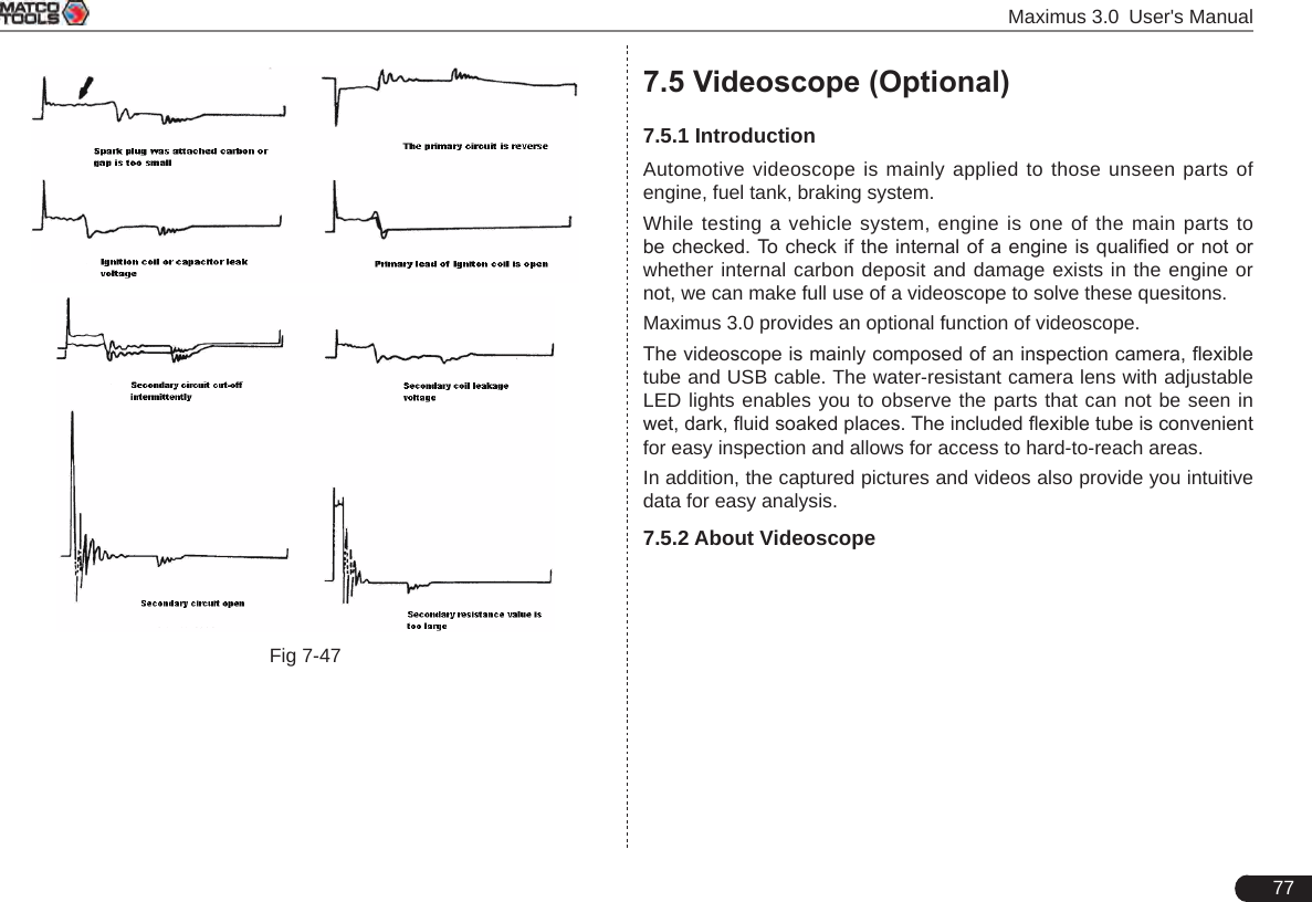
![Maximus 3.0 User's Manual79Net Weight Approx. 270g7.5.4 Connections & Operations1. Locate the data transmission port of the Maximus 3.0 handset. 2. Insert the data cable into the data transmission port of port of the Maximus 3.0 handset.3. Bend the neck of the flexible tube as desired and extend the camera with adjustable LED lights to some unseen or unreachable parts of engine, hydraulic system, nozzles etc. 4. After connections are properly made, press the [POWER] button on the Maximus 3.0 handset to turn it on. Wait until the system enters Job menu. Switch to the "Toolbox" module, tap "Applications" -> "Videoscope" to run it, then the screen will display the scene captured from the videoscope camera. 5. Adjust it until the lens stops in the desired place, then use the dial for LED light brightness to adjust the brightness. 6. Press the Snapshot button on the videoscope to take a photo. Alternatively, you can also press the Snapshot button on the Maximus 3.0 handset to take photos. To record a video, switch from Camera mode to Video mode and tap Record button on the screen to start recording.Images are captured in .jpg format and videos are recorded in .avi or .mp4 format. All photographings and videos are saved in DCIM folder where users can browse and replay it.](https://usermanual.wiki/Launch-Tech/DS601/User-Guide-4039375-Page-85.png)