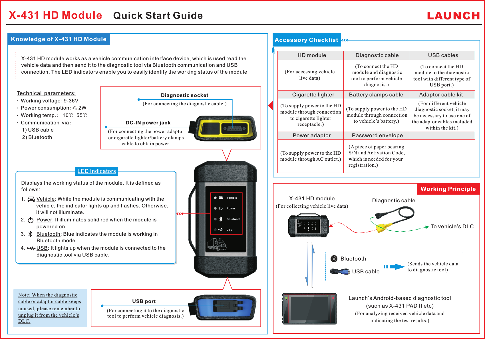
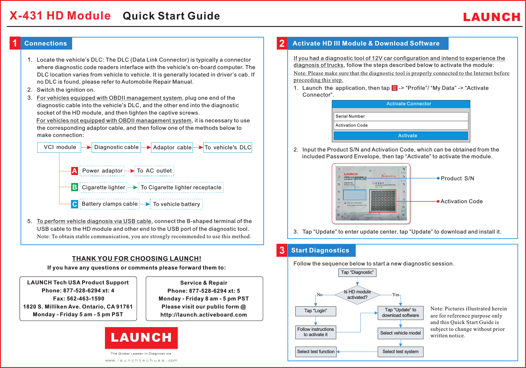
Launch Tech HDIII Heavy duty / Medium duty / Light duty Vehicle Communication Interface User Manual

Launch Tech Co., Ltd. Heavy duty / Medium duty / Light duty Vehicle Communication Interface Users Manual

Users Manual

X-431 HD Module    Quick Start Guide LAUNCH了解 诊 断 盒Knowledge of X-431 HD ModuleDiagnostic socket(For connecting the diagnostic cable.)DC-IN power jackUSB portDisplays the working status of the module.  t is defined as follows:I1.    Vehicle: While the module is communicating with the vehicle, the indicator lights up and flashes. Otherwise, it will not illuminate.2.    Power: It illuminates solid red when the module is powered on.3.    Bluetooth: Blue indicates the module is working in Bluetooth mode.4.    USB: It lights up when the module is connected to the diagnostic tool via USB cable.LED IndicatorsX-431 HD module works as a vehicle communication interface device, which is used read the vehicle data and then send it to the diagnostic tool via Bluetooth communication and USB connection. The LED indicators enable you to easily identify the working status of the module.Technical parameters: Working voltage:9-36V Power consumption:≤ 2W Working temp.:-10℃- 55℃ Communication via:   1) USB cable2) BluetoothNote: When the diagnostic cable or adaptor cable keeps unused, please remember to unplug it from the vehicle’s DLC.X-431 HD module(For collecting vehicle live data) Bluetooth To vehicle’s DLCDiagnostic cableWorking PrincipleUSB cableAccessory ChecklistHD module           Diagnostic cable           USB cables Cigarette lighter          Battery clamps cable           Adaptor cable kit                                                                                 (For accessing vehicle live data)(To connect the  module and diagnostic tool to perform vehicle diagnosis.)HD (To connect the module to the diagnostic tool with different type of USB port.)HD (A piece of paper bearing S/N and Activation Code, which is needed for your registration.)Power adaptor        Password envelope    (Sends the vehicle data to diagnostic tool) (For connecting the power adaptor or cigarette lighter/battery clamps cable to obtain power. (For connecting it to the diagnostic tool to perform vehicle diagnosis.)(For different vehicle diagnostic socket, it may be necessary to use one of the adaptor cables included within the kit.)(To supply power to the HD  module through connection to vehicle’s battery.)(To supply power to the HD module through connection to cigarette lighter receptacle.)(To supply power to the HD module through AC outlet.)Launch’s Android-based diagnostic tool(such as X-431 PAD II etc)(For analyzing received vehicle data and indicating the test results.)
1.  The DLC (Data Link Connector) is typically a connector where diagnostic code readers interface with the vehicle's on-board computer. 2. 3. 5.   To perform vehicle diagnosis via USB cable, connect the B-shaped terminal of the USB cable to the HD module and other end to the USB port of the diagnostic tool. Note: To obtain stable communication, you are strongly recommended to use this method.Locate the vehicle’s DLC: The DLC location varies from vehicle to vehicle. It is generally located in driver’s cab. If no DLC is found, please refer to Automobile Repair Manual.Switch the ignition on.For vehicles equipped with OBDII management system, plug one end of the diagnostic cable into the vehicle’s DLC, and the other end into the diagnostic socket of the HD module, and then tighten the captive screws.      For vehicles not equipped with OBDII management system, it is necessary to use the corresponding adaptor cable, and then follow one of the methods below to make connection:LAUNCH1Connections3 THANK YOU FOR CHOOSING LAUNCH!If you have any questions or comments please forward them to:  LAUNCH Tech USA Product SupportPhone: 877-528-6294 xt: 4   Fax: 562-463-15901820 S. Milliken Ave. Ontario, CA 91761Monday - Friday 5 am - 5 pm PSTService & RepairPhone: 877-528-6294 xt: 5  Monday - Friday 8 am - 5 pm PSTPlease visit our public form @http://launch.activeboard.comLAUNCHVCI module Diagnostic cableCigarette lighterBattery clamps cableAdaptor cable To vehicle's DLCTo Cigarette lighter receptacleTo vehicle batteryPower adaptor To AC outletABC2 Activate HD III Module & Download SoftwareIf you had a diagnostic tool of 12V car configuration and intend to experience the diagnosis of trucks, follow the steps described below to activate the module:Note: Please make sure that the diagnostic tool is properly connected to the Internet before proceeding this step.1. Launch the application, then tap      -> “Profile”/ “My Data” -> “Activate Connector”.2. Input the Product S/N and Activation Code, which can be obtained from the included Password Envelope, then tap “Activate” to activate the module.3. Tap “Update” to enter update center, tap “Update” to download and install it.If you had a diagnostic tool of 12V car configuration and intend to experience the diagnosis of trucks, follow the steps described below to activate the module:Note: Please make sure that the diagnostic tool is properly connected to the Internet before proceeding this step.1. Launch the application, then tap      -> “Profile”/ “My Data” -> “Activate Connector”.2. Input the Product S/N and Activation Code, which can be obtained from the included Password Envelope, then tap “Activate” to activate the module.3. Tap “Update” to enter update center, tap “Update” to download and install it.Product S/NActivation CodeTap “Diagnostic”Select vehicle modelSelect test systemSelect test functionTap “Login”Is HD module activated?NoTap “Update” to download softwareYesFollow instructions to activate itStart DiagnosticsNote: Pictures illustrated herein are for reference purpose only and this Quick Start Guide is subject to change without prior written notice.Follow the sequence below to start a new diagnostic session.X-431 HD Module    Quick Start GuideActivate ConnectorSerial NumberActivation CodeActivate
FCC STATEMENT 1. This device complies with Part 15 of the FCC Rules. Operation is subject to the following two conditions: (1) This device may not cause harmful interference. (2) This device must accept any interference received, including interference that may cause undesired operation. 2. Changes or modifications not expressly approved by the party responsible for compliance could void the user's authority to operate the equipment.  NOTE: This equipment has been tested and found to comply with the limits for a Class B digital device, pursuant to Part 15 of the FCC Rules. These limits are designed to provide reasonable protection against harmful interference in a residential installation. This equipment generates uses and can radiate radio frequency energy and, if not installed and used in accordance with the instructions, may cause harmful interference to radio communications. However, there is no guarantee that interference will not occur in a particular installation. If this equipment does cause harmful interference to radio or television reception, which can be determined by turning the equipment off and on, the user is encouraged to try to correct the interference by one or more of the following measures:    Reorient or relocate the receiving antenna.    Increase the separation between the equipment and receiver.    Connect the equipment into an outlet on a circuit different from that to which the receiver is connected.    Consult the dealer or an experienced radio/TV technician for help.   FCC Radiation Exposure Statement This equipment complies with FCC radiation exposure limits set forth for an uncontrolled environment. This equipment should be installed and operated with minimum distance 20cm between the radiator & your body

Navigation menu