Launch Tech PADV Automotive intelligent diagnostic tools User Manual
Launch Tech Co., Ltd. Automotive intelligent diagnostic tools
UserManual.wiki
>
Launch Tech
>
PADV User Manual
User Manual
Navigation menu
Upload a User Manual
Namespaces
Wiki Guide
HTML
PDF
Info
Views
User Manual
Discussion / Help
Navigation
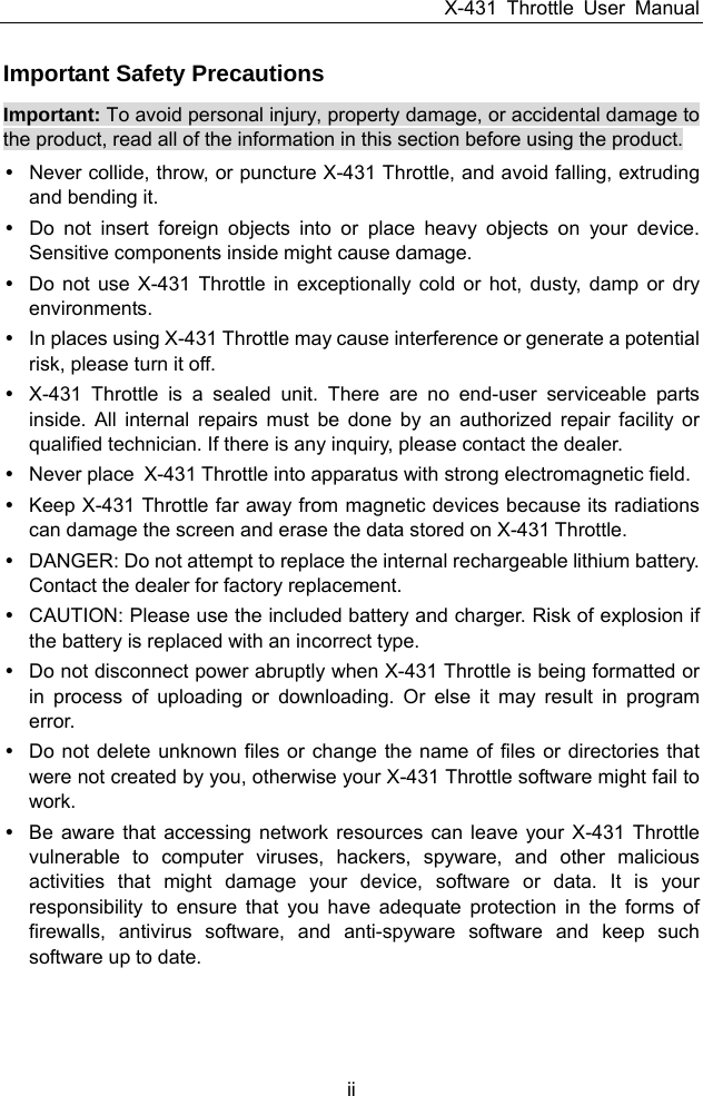

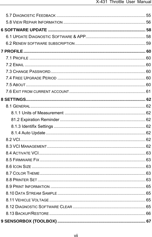
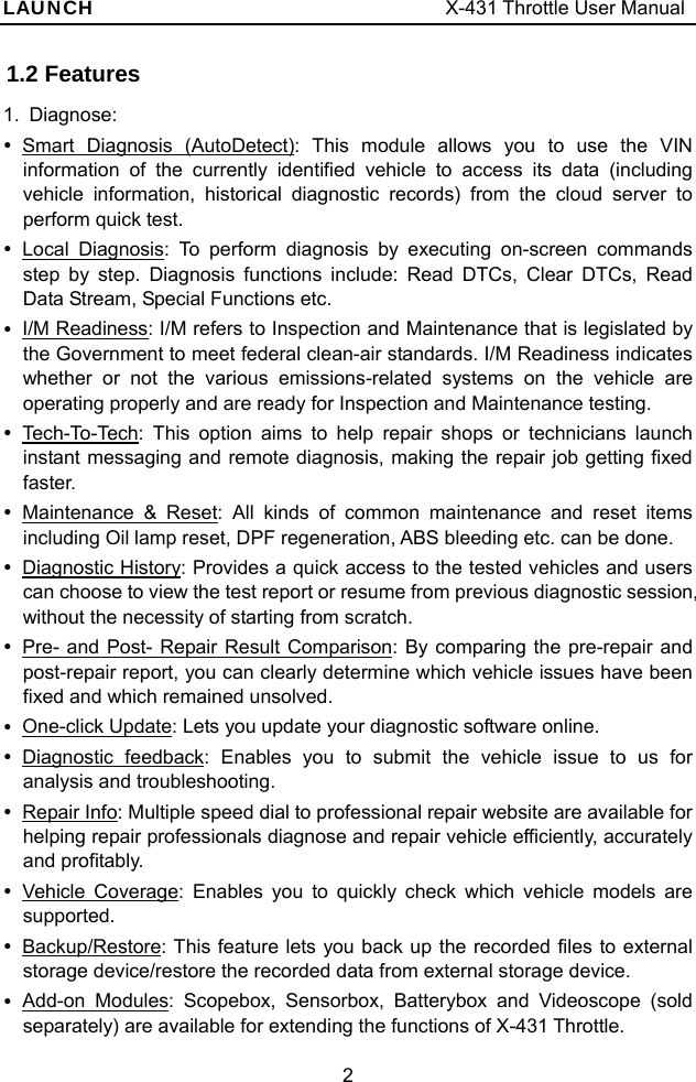
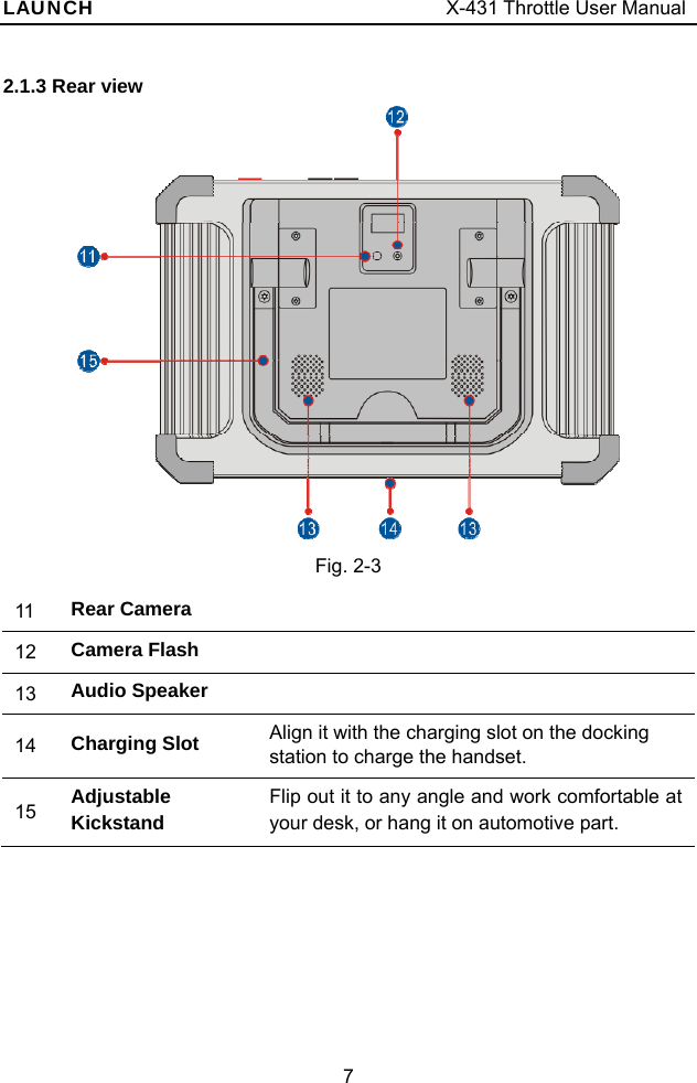
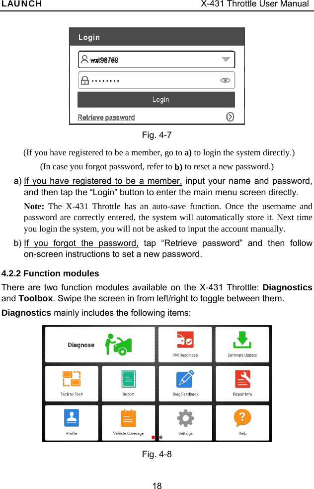
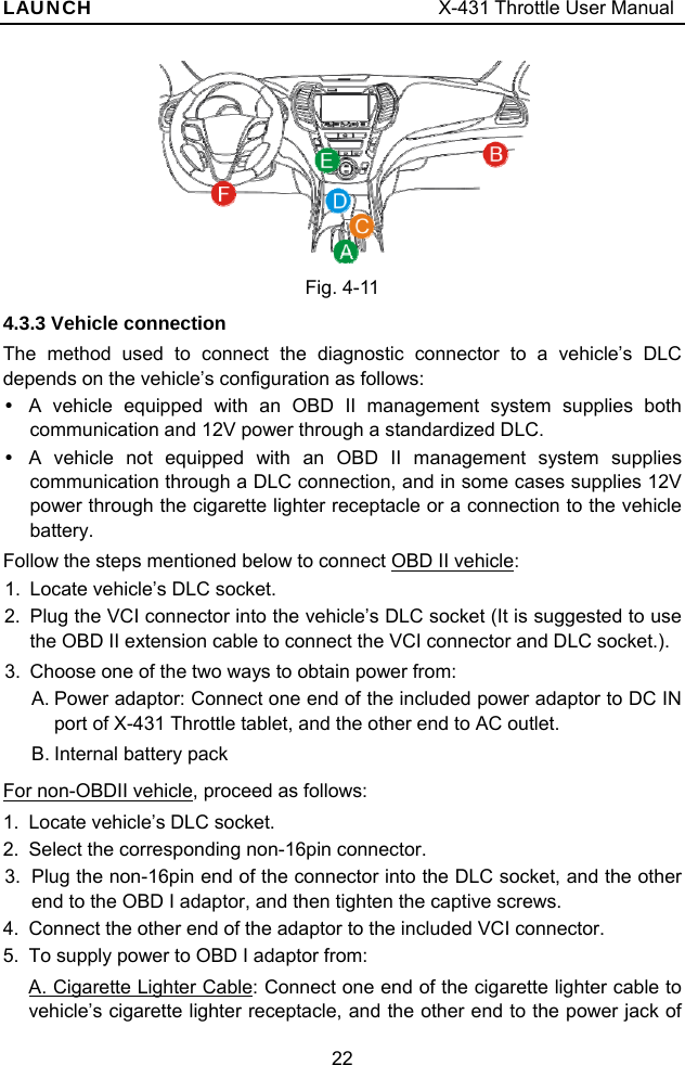
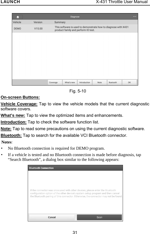
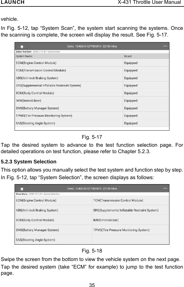
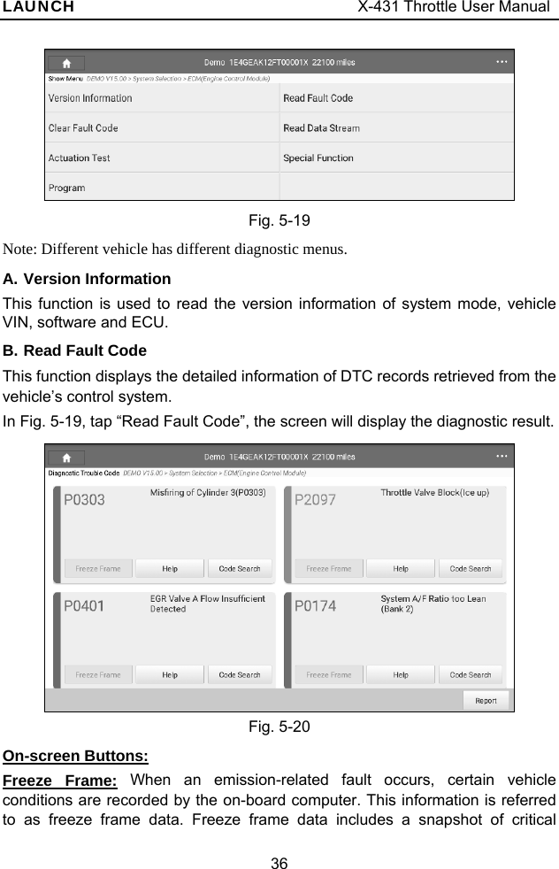
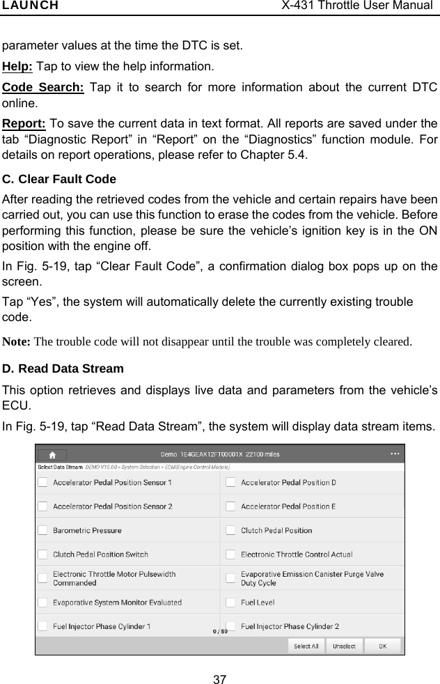
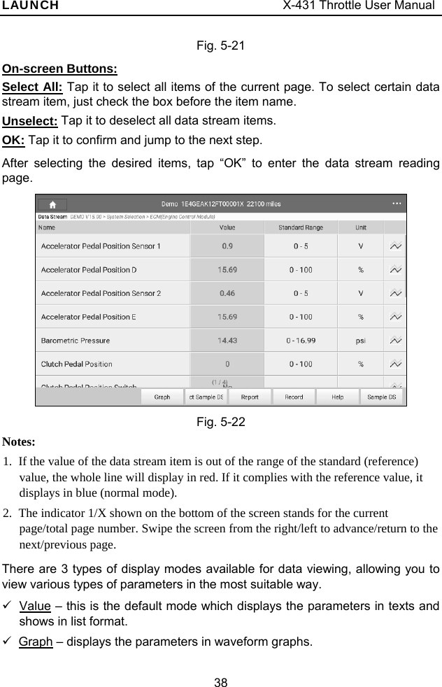
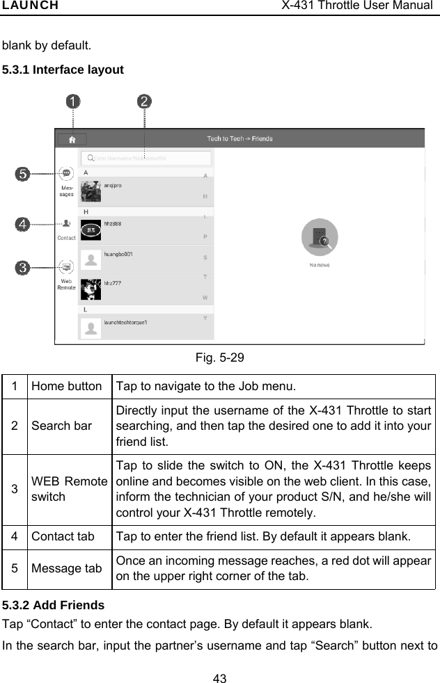
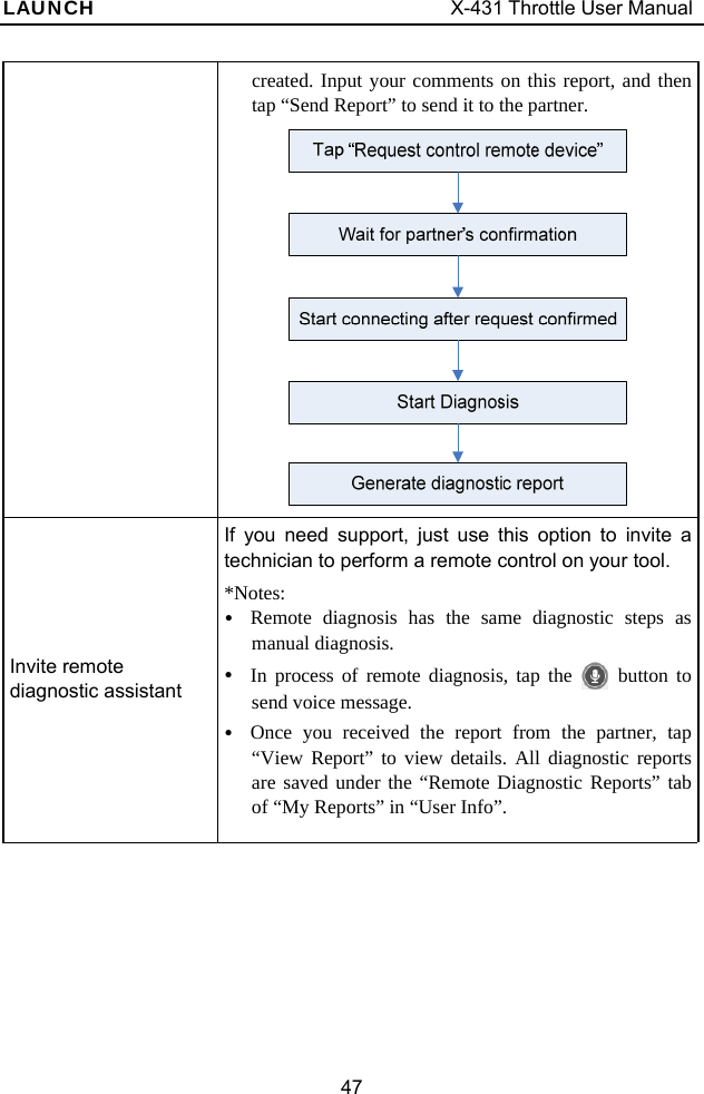
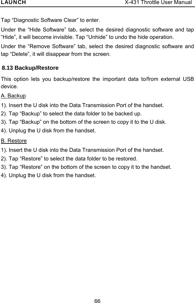
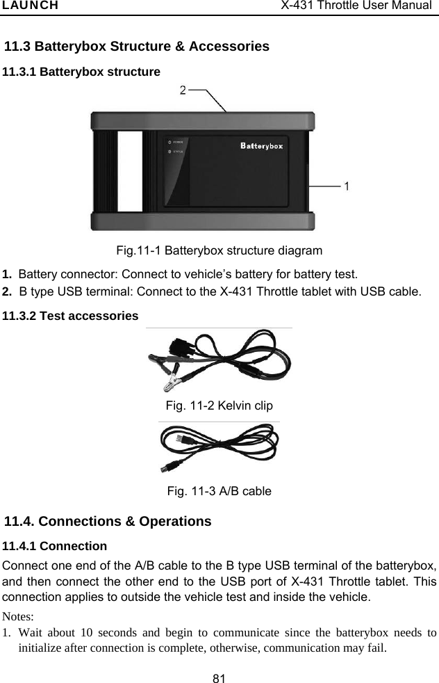
![LAUNCH X-431 Throttle User Manual 5 2 Knowledge of X-431 Throttle There are three main components to the X-431 Throttle system: y X-431 Throttle tablet – the central processor and monitor for the system (See Chapter “2.1”) y Docking Station – the platform for charging X-431 Throttle tablet and extending functions (For details, please refer to Chapter 2.2.) y VCI device – the device for accessing vehicle data (See Chapter “2.3”) 2.1 X-431 Throttle tablet The handset acts as the central processing system, which is used to receive and analyze the live vehicle data from the VCI connector and then output the test result. 2.1.1 Top view Fig. 2-1 1 Memory Card Slot To store the memory card for storage expansion. 2 Charging Port Reserved for charging the handset. 3 Power/Screen Lock Button To turn the handset on/off with long press, or lock the screen with short press. 4 Volume Buttons To adjust the volume. *Note: Press and hold [POWER] and [VOL -] key to](https://usermanual.wiki/Launch-Tech/PADV/User-Guide-3967457-Page-15.png)
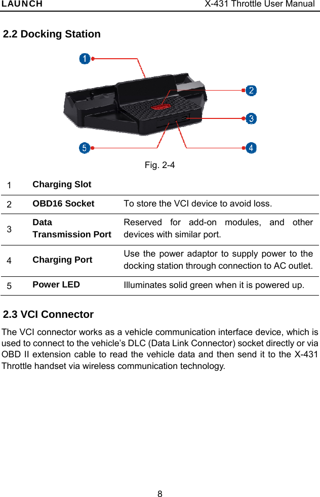
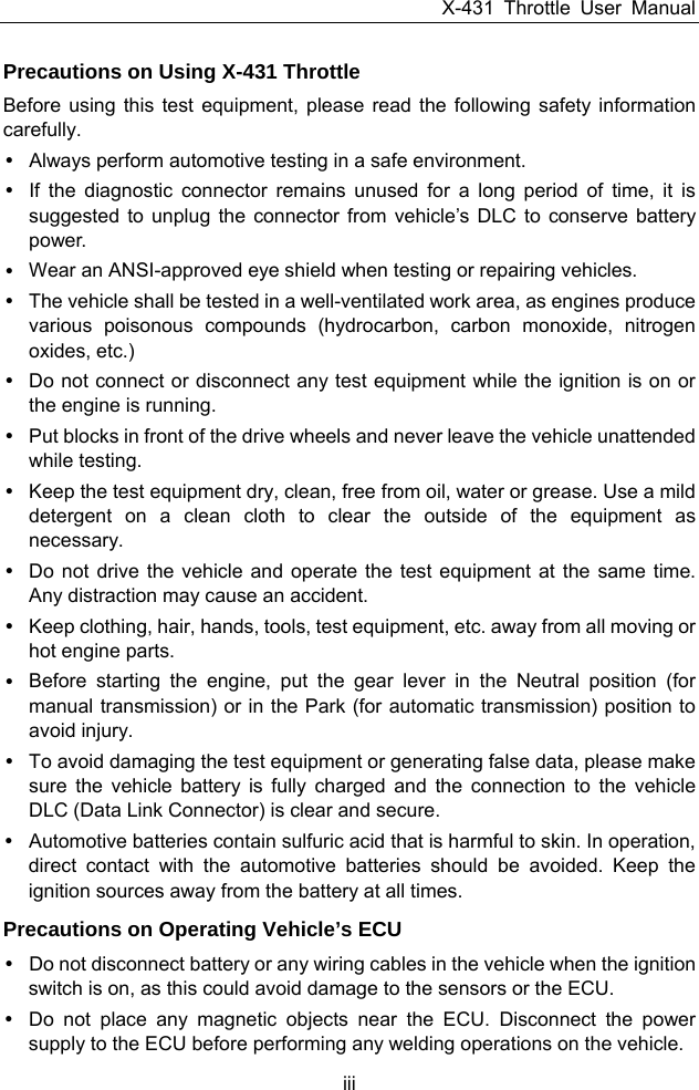
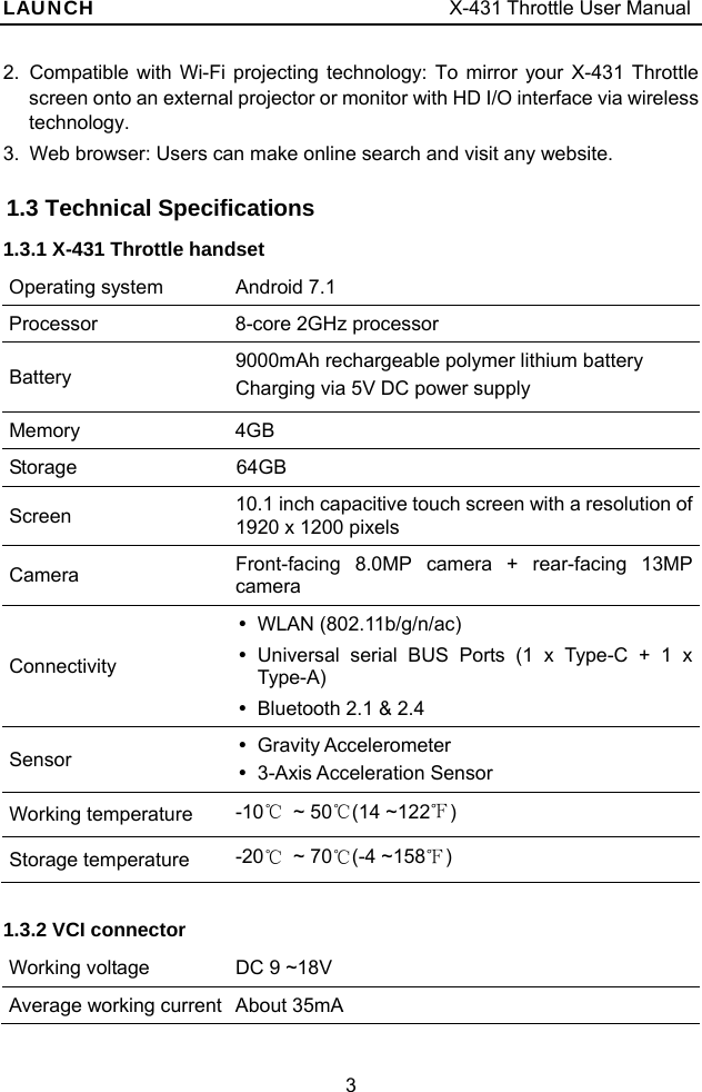
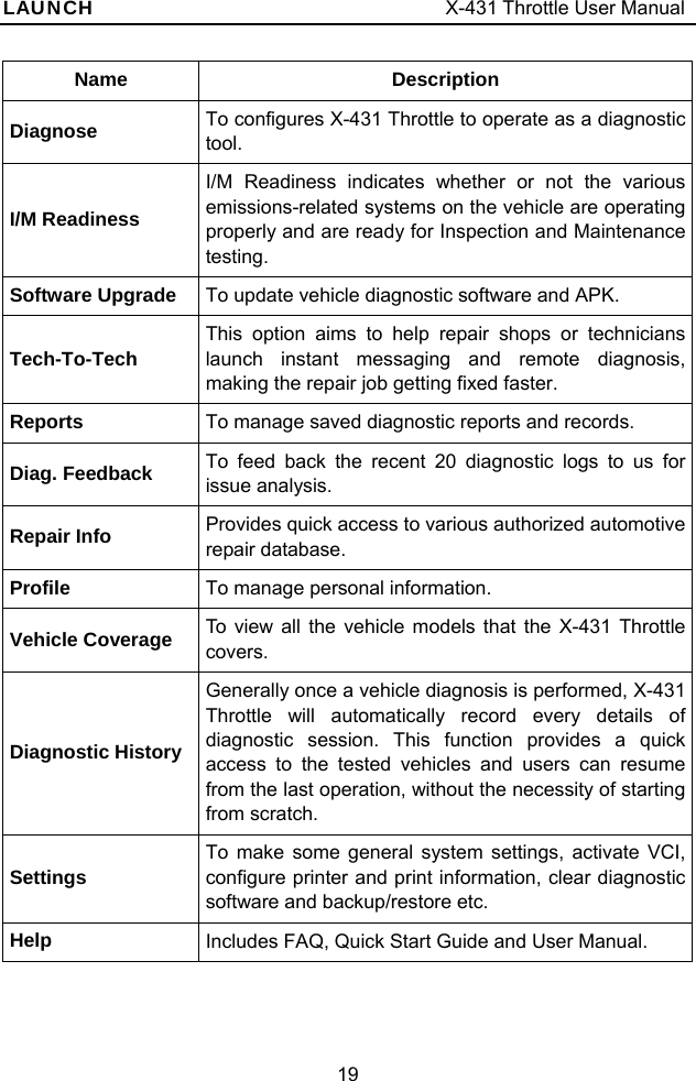
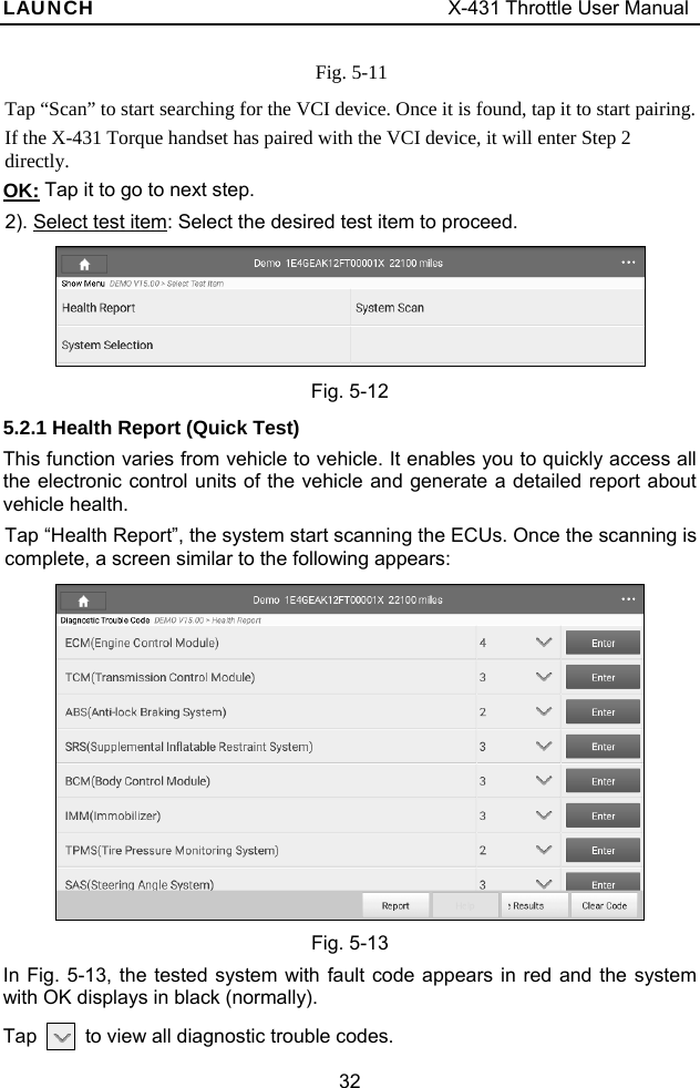
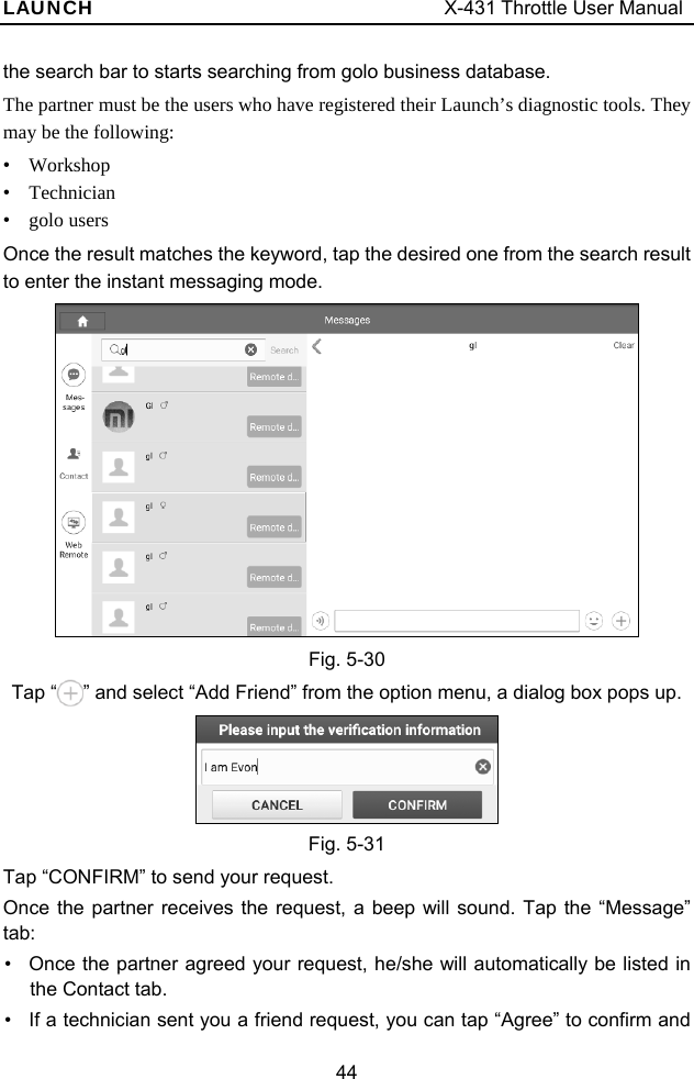
![LAUNCH X-431 Throttle User Manual 11 3 Preparations 3.1 Charging X-431 Throttle Choose any of the followings to charge your handset: A. Use the included 5V power adaptor: Connect one end of the power adaptor to Type C charging port of the handset, and the other end to the AC outlet. Never use other similar adaptors to charge it. B. Use the docking station: Follow the steps described as below to charge your handset: 1. Locate the charging slot on the bottom of the handset and docking station. 2. Align the charging slots, and then dock the tablet into the station to ensure that it is firmly seated on the docking station. 3. Insert one end of the included power cord to the charging port of the docking station, then the other end into the AC outlet. The charging LED illuminates solid red while charging. 4. Once it illuminates solid green, it indicates that the battery is fully charged. Disconnect the docking station from the AC outlet. 3.2 Using Your Battery If the battery remains unused for a long period of time or the battery is completely discharged, it is normal that the tool will not power on while being charged. Please charge it for a period of 5 minutes and then turn it on. Please use the included power adaptor to charge your tool. No responsibility can be assumed for any damage or loss caused as a result of using power adaptors other than the one supplied. While X-431 Throttle has low battery, a beep will sound. If it is very low, X-431 Throttle will be switched off automatically. 3.3 Power on/off 3.3.1 Power on Press [POWER] to turn the tool on. *Note: If it is the first time you have used this tool or the tool remains idle for a long period of time, the tool could fail to turn on. Please charge the tool for a minimum of 5](https://usermanual.wiki/Launch-Tech/PADV/User-Guide-3967457-Page-21.png)
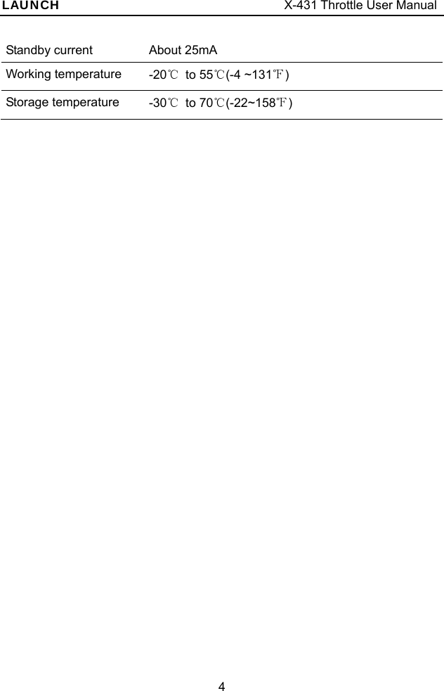
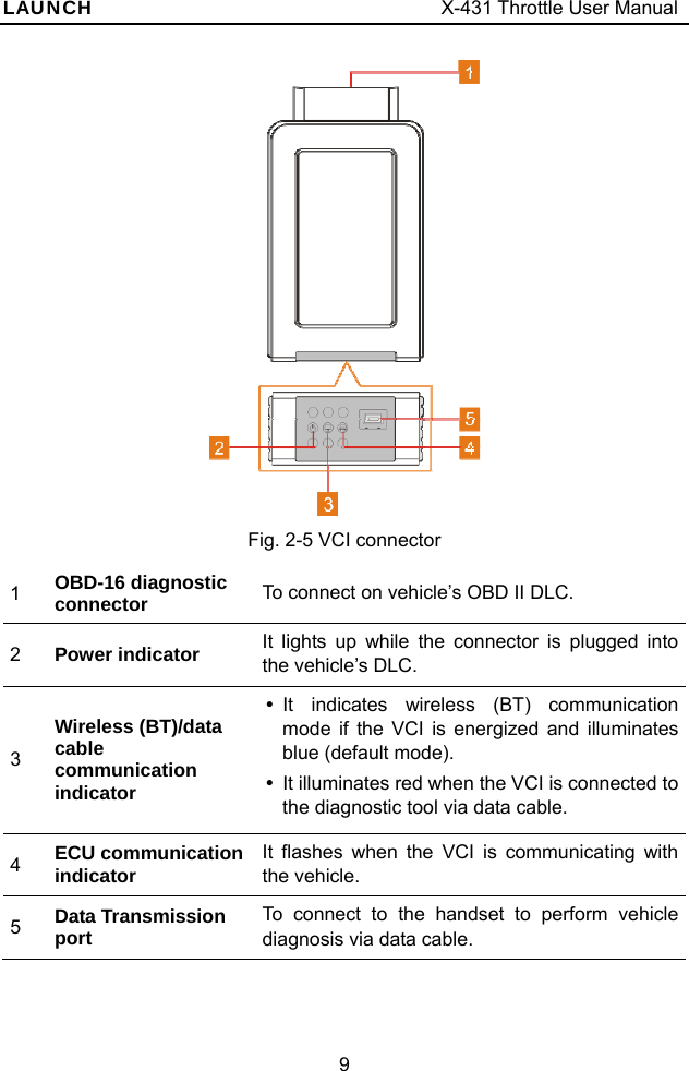
![LAUNCH X-431 Throttle User Manual 12 minutes and attempt to turn on again. 3.3.2 Power off Press [POWER] for 3 seconds, an option menu will pop up on the screen. Tap “Power off” to turn the tool off. To perform a forced shutdown, press [POWER] for more than 8 seconds until the screen goes dark. 3.4 Tips on Finger Operations Single-tap: To select a item or launch a program. Double-tap: To zoom in so that the text on a webpage appears in a column that fits your device’s screen. Long press: Tap and hold on the current interface or area until a contextual menu pops up on the screen, and then release it. Slide: To jump to different pages. Drag: Tap the desktop icon and drop it to other location. Spread apart/pinch together: To zoom in manually, place two fingers on the screen and then spread them apart. To zoom out, place two fingers apart on the screen and then pinch them together.3.5 Lock & Unlock Screen Many screen lock modes are available on X-431 Throttle. *Note: You are recommended to set screen lock as “None” since X-431 Throttle is a frequently used diagnostic tool. 3.5.1 Lock the screen When it is ON, press [POWER] once to lock the screen; The system will lock the screen automatically after X-431 Throttle remains idle over the preset standby time.](https://usermanual.wiki/Launch-Tech/PADV/User-Guide-3967457-Page-22.png)
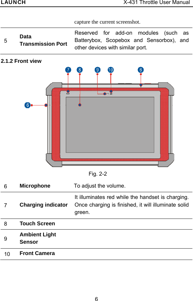
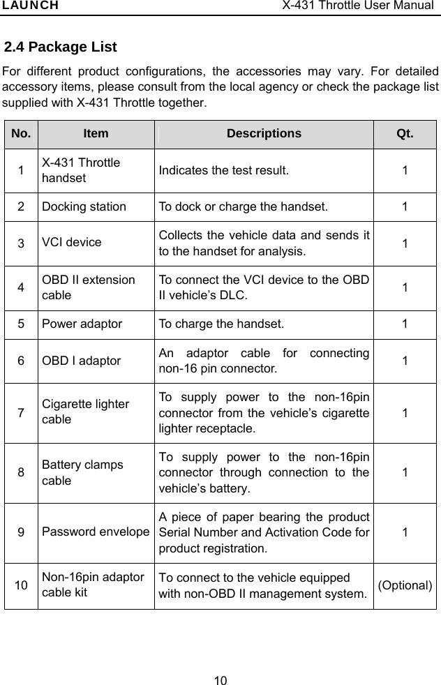
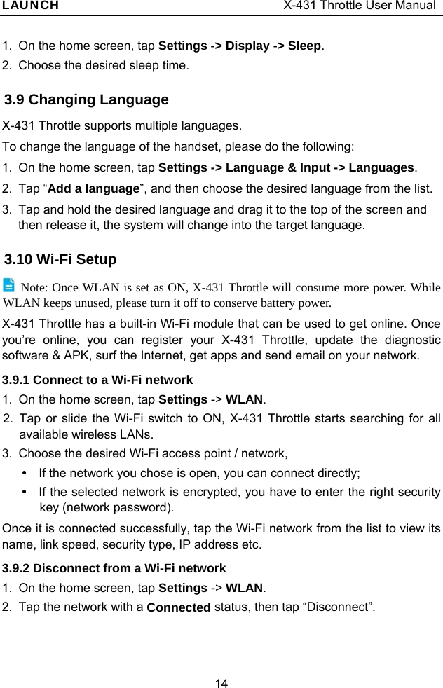
![LAUNCH X-431 Throttle User Manual 13 3.5.2 Unlock the screen Press [POWER] to activate the screen and drag the lock to “Unlock” position. *Note: If you define as unlock using the pattern, you have to draw the right target pattern to unlock it. 3.6 Screen Layout 1. Preview the screen Tap and hold any blank area on the home screen, a function menu will pop up at the bottom of the screen. It mainly includes wallpapers, lock screen wallpapers, widgets, settings and apps. 2. On-screen buttons There are 6 on-screen buttons available on the bottom of the screen. y Back: Tap to return to the previous screen. y Home: Tap to jump to the Android’s home screen. y Recent App: Tap to view the recently launched applications and running applications. y Screenshot: Tap to capture the current screen. y Downloadable: Once some upgradable diagnostic software is detected, the icon will turn highlighted. y VCI Connection : Shows whether the VCI device is properly connected or not. 3.7 Adjust Brightness Tips: Reducing the brightness of the screen is helpful to save the power of X-431 Throttle. 1. On the home screen, tap Settings -> Display -> Brightness level. 2. Drag the slider to adjust it. 3.8 Set Standby Time If no activities are made within the defined standby period, the screen will be locked automatically and the system enters sleep mode to save power.](https://usermanual.wiki/Launch-Tech/PADV/User-Guide-3967457-Page-23.png)
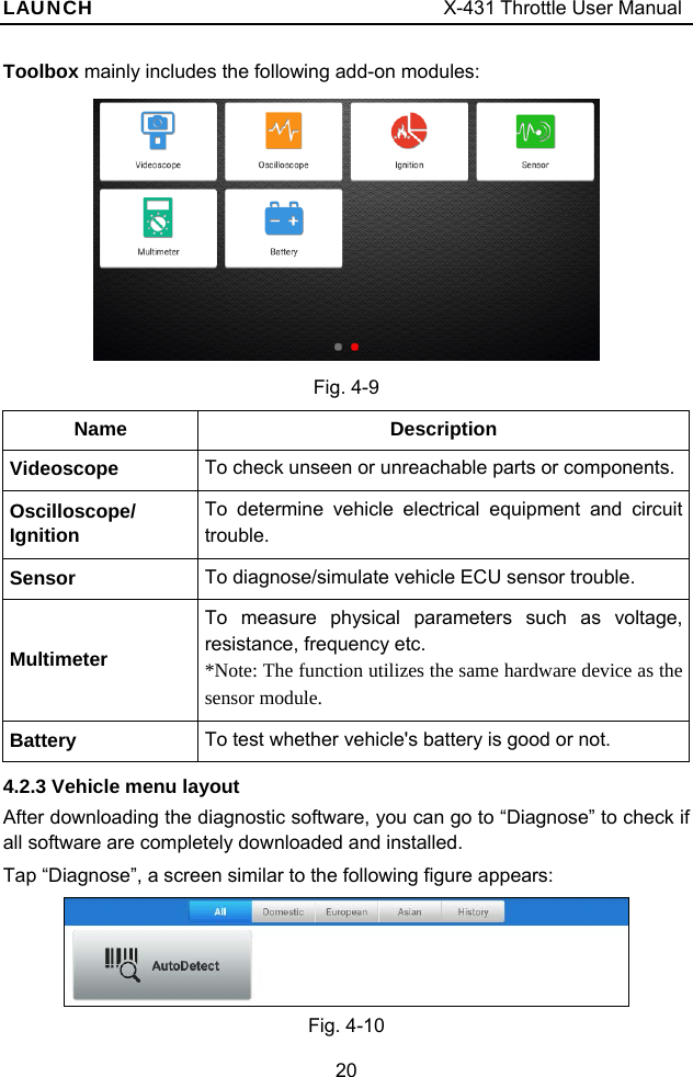

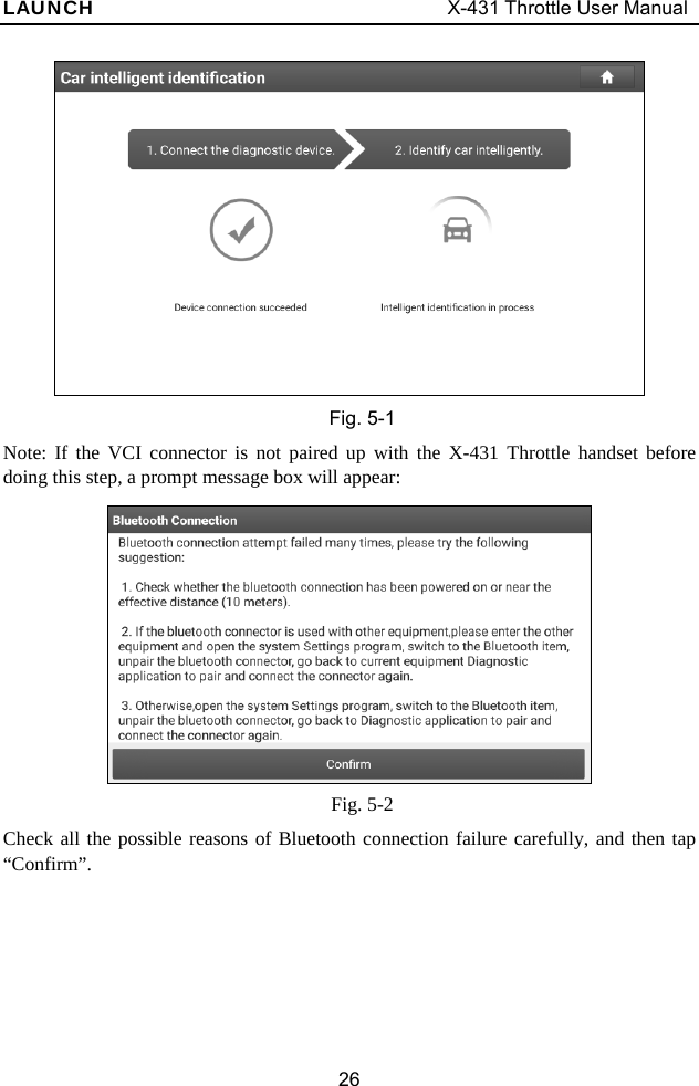
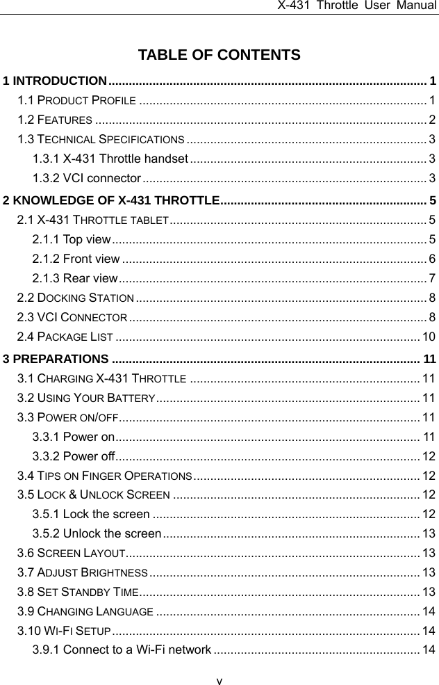
![LAUNCH X-431 Throttle User Manual 54 2) O2 Sensors 3) Catalyst 4) Evaporative System 5) O2 Sensor Heater 6) Secondary air Injection 7) Heated Catalyst 8) A/C system I/M refers to Inspection and Maintenance that is legislated by the Government to meet federal clean-air standards. I/M Readiness indicates whether or not the various emissions-related systems on the vehicle are operating properly and are ready for Inspection and Maintenance testing. The purpose of the I/M Readiness Monitor Status is to indicate which of the vehicle’s Monitors have run and completed their diagnosis and testing, and which ones have not yet run and completed testing and diagnosis of their designated sections of the vehicle’s emissions system. The I/M Readiness Monitor Status function also can be used (after repair of a fault has been performed) to confirm that the repair has been performed correctly, and/or to check for Monitor Run Status. Tap [I/M Readiness] on the Job Menu to start checking. After checking all I/M readiness status, the screen will output the result: Figure 5-40](https://usermanual.wiki/Launch-Tech/PADV/User-Guide-3967457-Page-64.png)
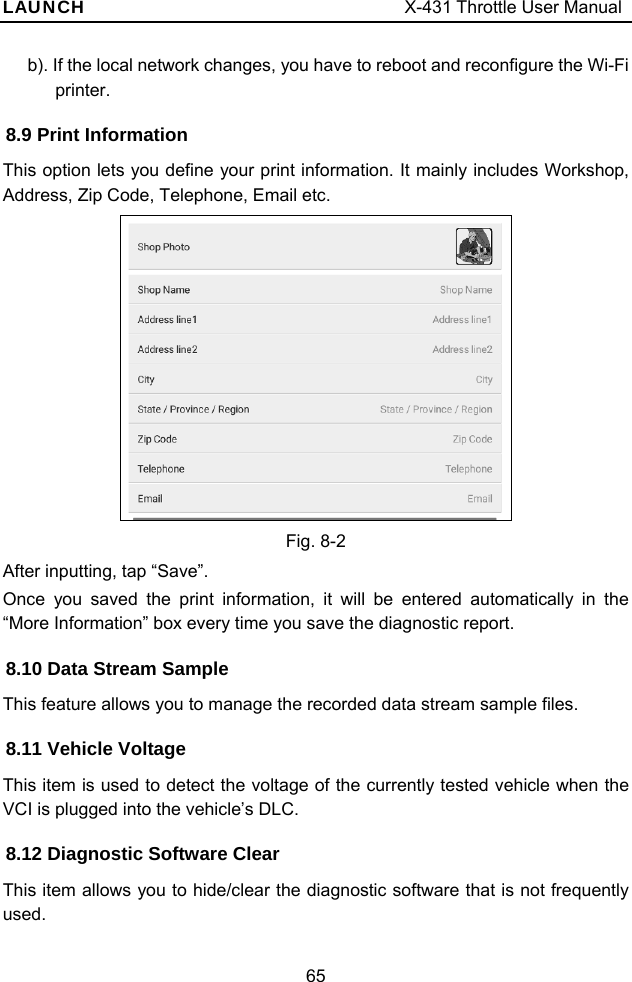
![LAUNCH X-431 Throttle User Manual 64 The App is compatible with the “Wi-Fi Printer” (sold separately) and “System” (external printer). Follow the steps below to connect the Wi-Fi printer. 1. Tap “Printer Set”. Below describes how to configure the Wi-Fi Printer. A. If it is the first time you have operated this printer, please proceed the following: 2. For initial use, you are suggested to reset the printer: Press and hold [MODE] & [FEED] for 8 seconds, the following resetting command will be printed out: at + default = 1 ok at + reboot = 1 rebooting... 3. Tap “Reset” to configure Wi-Fi printer. Step 1: Connect the printer: Tap “Scan” to select the desired printer hotspot named with X-431PRINTER-XXXX (XXXX stands for 4 characters), and then tap “Connect” to enter Step 2. Step 2: Join the printer into LAN: Tap “Scan” to select the desired local Wi-Fi network from the list, and type in the security password (If it is an open network, password is not required), and then tap “Confirm”. 4. Once the Wi-Fi network of the printer is connected and the printer is found, tap “Test Print” to test the printing. Now you can use the Wi-Fi printer to print! If the printer is not found, please reset the printer to default factory settings (refer to Step 2 for details) and check whether the current device and the printer are on the same LAN. B. If you have configured the Wi-Fi printer to the LAN: 2. Tap “Connect to Printer”: a). If the local network remains as it is, tap “Test Print” directly to test the printing.](https://usermanual.wiki/Launch-Tech/PADV/User-Guide-3967457-Page-74.png)
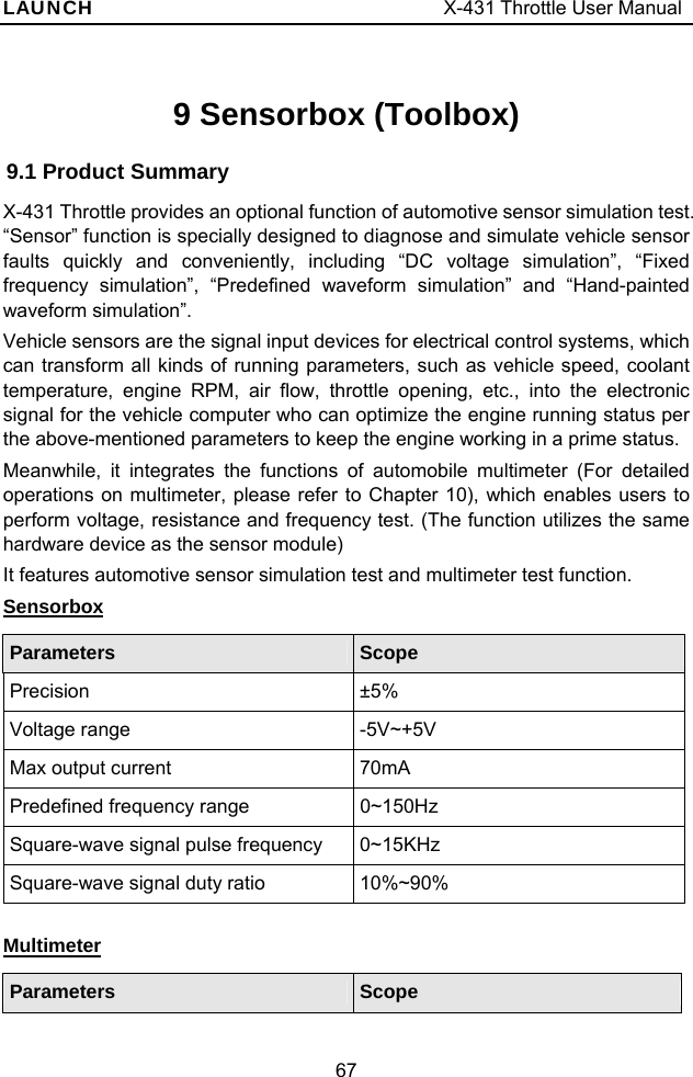
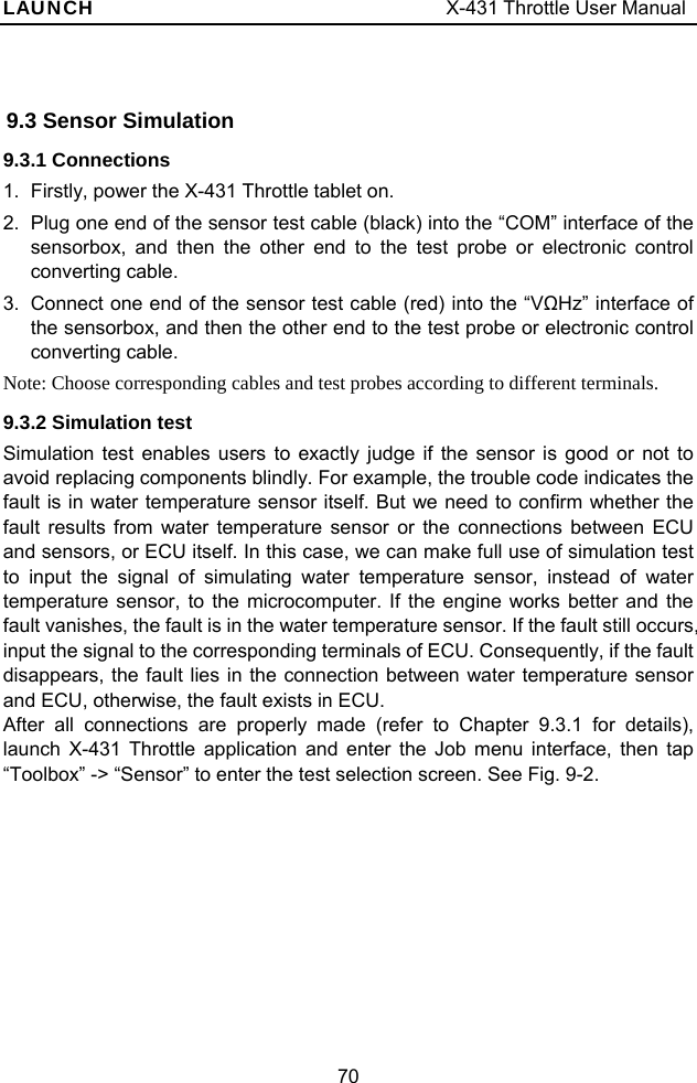
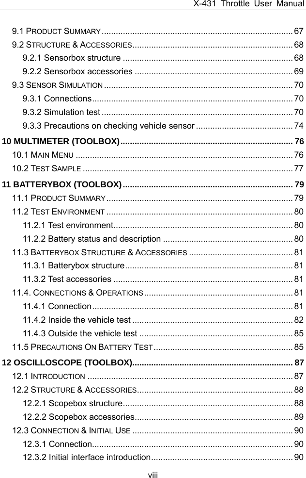
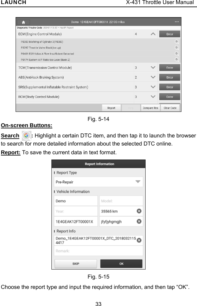
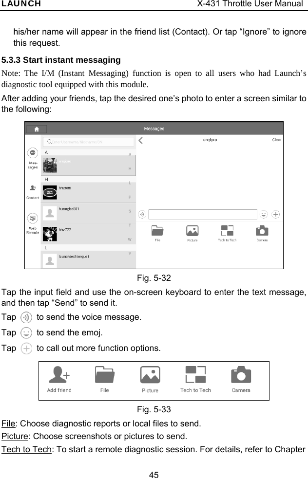
![LAUNCH X-431 Throttle User Manual 71 Fig. 9-2 1. DC voltage simulation In Fig. 9-2, tap [Current voltage], then tap “+” or “-” to adjust the output voltage value. Alternatively, user can also tap edit box, then use the on-screen keyboard to input the desired value directly. After selecting or inputting the desired voltage based on the working characteristics of sensor, tap the button, then the X-431 Throttle will begin to output the simulation voltages. Please note the red probe is the output terminal of simulation voltage. 2. Fixed frequency simulation This option enables you to simulate the square wave signal of pulse frequency of 0.1 ~ 15 kHz, amplitude range of -5V ~ +5V and duty cycle 10% ~ 90%. In Fig. 9-2, tap “Fixed frequency simulation” to enter a screen similar to Fig. 9-3. Fig. 9-3](https://usermanual.wiki/Launch-Tech/PADV/User-Guide-3967457-Page-81.png)
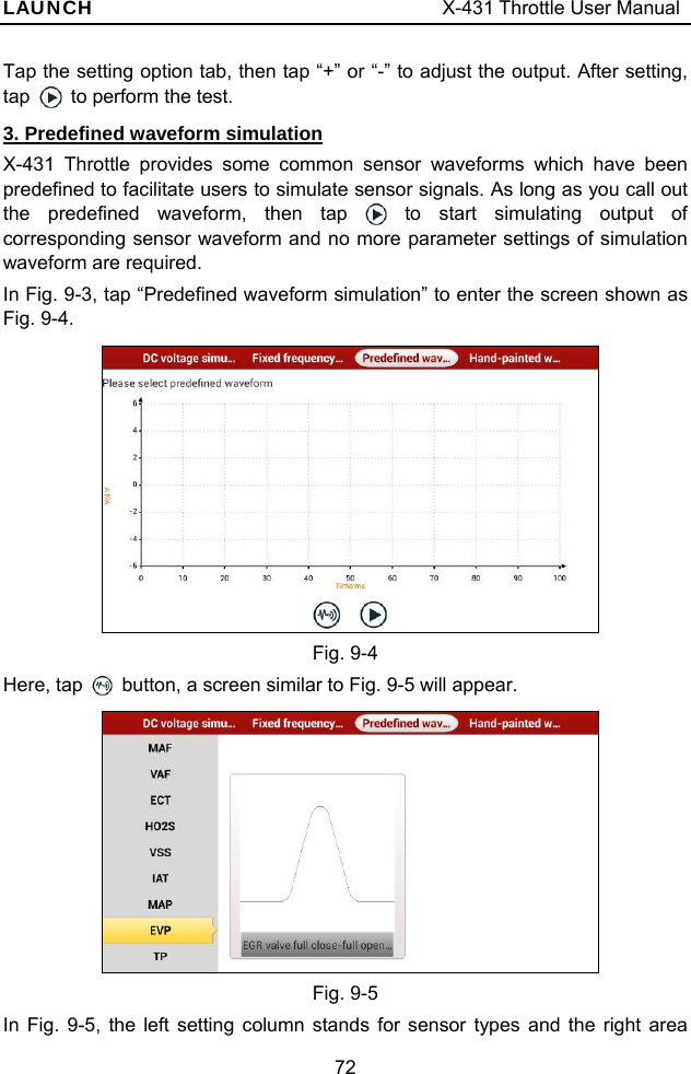
![LAUNCH X-431 Throttle User Manual 74 Fig. 9-7 In Fig. 9-7, tap button to perform simulation test. 4. Hand-painted waveform simulation This option offers great convenience for users to simulate special waveform or fault wave. Users only draw the shape of waveform which needs to be simulated in central drawing area, and then configure some parameters on the top, namely high level, low level, and cycle of waveform, then tap , X-431 Throttle will output a waveform as desired. Warning: Just draw a complete periodic waveform (when it is output, the system will regard the waveform in the drawing area as a periodic one). Users should draw as large as wave in drawing zone so that the system can sample more points to reduce tolerance. In Fig. 9-2, tap “Hand-painted waveform simulation”, a screen similar to Fig. 9-8 will appear. Fig. 9-8 Button descriptions: []: Save the current waveform. []: Loads the previously saved hand-drawn waveform. []: Clear all hand-drawn waveform. []: Click to call out the predefined waveform for reference. []: Continues the following operation. 9.3.3 Precautions on checking vehicle sensor y Hold the connector when plugging or unplugging it. Do not pull the cable for](https://usermanual.wiki/Launch-Tech/PADV/User-Guide-3967457-Page-84.png)
![LAUNCH X-431 Throttle User Manual 77 The following operations can be done: []: Erases the currently displayed waveform and display it starting from the left. []: Reduces the range and zoom in the waveform. []: Increase the range and zoom out the waveform. []: Starts or stops the testing process. 10.2 Test Sample Knock sensor testing (1) Resistance test for knock sensor Switch ignition “OFF”, unplug the wire connector of knock sensor, test the resistance between the wire terminal and the case of knock sensor with “Resistance test” function, it shall be ∞ (disconnected), and if it is 0Ω(conductive), which means the knock sensor shall be replaced. For the magnetostriction knock sensor, it can also test the resistance by the “Resistance measurement” function; the resistance shall be compliant with the specified value (see specific service manual for the detailed data), otherwise, the knock sensor shall be replaced. (2) Checking for the output signal of knock sensor Unplug the wire connector of knock sensor, check voltage between knock sensor connector terminal and ground wire of knock, it should be output pulse voltage; otherwise, the knock sensor shall be replaced. Coolant temperature sensor testing (1) Resistance test for coolant temperature sensor On vehicle testing: Switch ignition “OFF” and unplug the wire connector of coolant temperature sensor, then use the “Resistance measurement” to test the Resistance between two terminals of sensor. The relationship between the resistance and the temperature is in inversely proportion (negative temperature coefficient), which shall be less than 1kΩ during warming up. Independent testing: Unplug the wire connector of coolant temperature sensor, then remove the sensor from the engine; place the sensor into a breaker with water and heat the water, then use the “Resistance measurement” to test the Resistance between two terminals of coolant temperature sensor at different water temperature. Compared the measured value with the standard value, if the Resistance is not](https://usermanual.wiki/Launch-Tech/PADV/User-Guide-3967457-Page-87.png)

![LAUNCH X-431 Throttle User Manual 82 2. Red lamp on the batterybox means it has been successfully powered up; If the green light is always on, it indicates the clip is well connected; while the green light blinks, it indicates that the clip has poor contact. Do not perform any test until the clip and A/B cable are properly connected. 11.4.2 Inside the vehicle test Battery test and charging system & actuation system test can be done in this mode. 1. Battery test Enter battery test main menu, and select a desired test environment as shown in Fig. 11-4. Fig. 11-4 Notes: The sequences of inside the vehicle and outside the vehicle test are almost the same, but under inside the vehicle condition, all loads in vehicles must be powered off for getting an exact test value. 1. Firstly, the system detects whether floating electricity exists or not before testing. If yes, turn on the headlamp to remove it. Otherwise, the system starts test program directly. 2. Tap [Inside the vehicle], the system starts detecting floating electricity automatically. If floating electricity is detected, it will prompt you to turn on the headlamp. 3. Follow the on-screen instructions to turn on headlamp, the system starts removing floating electricity. 4. Once the floating electricity is removed, a prompt message box “The floating electricity has been removed, please turn off the headlamp to continue the testing” will appear on the screen. 5. Follow the on-screen instructions to turn off the headlamp and tap [OK], the](https://usermanual.wiki/Launch-Tech/PADV/User-Guide-3967457-Page-92.png)
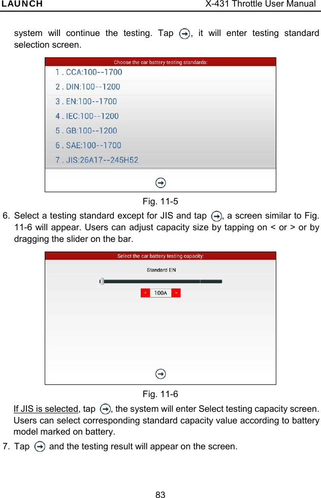
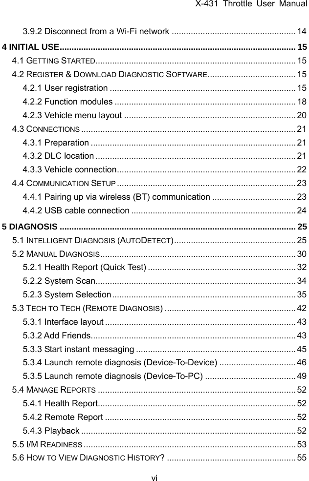
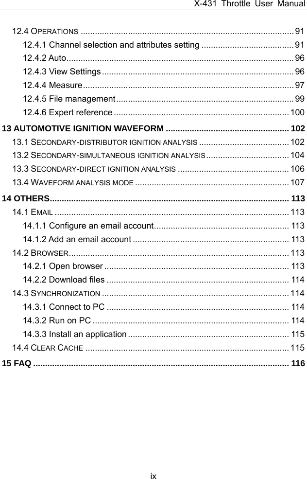
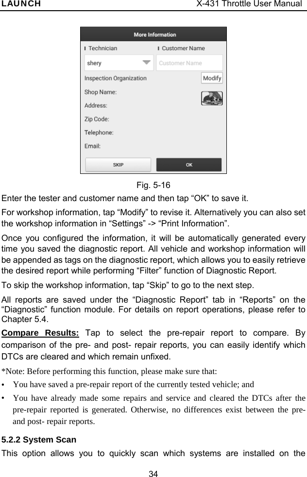
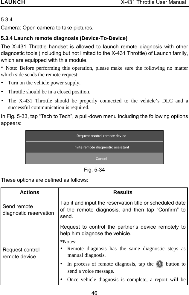
![LAUNCH X-431 Throttle User Manual 84 Fig. 11-7 []: Tap it to perform the charging system and starting system test. []: Tap to test it again. []: Tap it to reset the test. 2. Charging system and starting system test While performing this test, the battery’s charging voltage value and starting voltage can be obtained in case of engine starting and accelerating. Based on the data, the system will judge whether battery’s charging and actuation status is normal or not. Tap in Fig. 11-7, a dialog box will pop up as Fig. 11-8. Fig. 11-8 After detecting engine starting, follow the instructions on the screen to increase the speed. The system begins to receive test data information after acceleration was detected, as shown in Fig. 11-9.](https://usermanual.wiki/Launch-Tech/PADV/User-Guide-3967457-Page-94.png)
![LAUNCH X-431 Throttle User Manual 85 Fig. 11-9 Tap [OK], test data will be shown on the screen. Notes: It is unnecessary to perform charging system and start system test after finishing battery test, but battery test must be done before undergoing charging system and starting system test. 11.4.3 Outside the vehicle test It only applies to battery test and detecting floating electricity will be ignored while performing battery test. On Fig. 11-4, tap [Outside the vehicle] to select battery test standard. The following operation steps are identical to Steps 6~7 in Chapter 11.4.2 Battery test. Please refer to it for details. 11.5 Precautions On Battery Test For the purpose of getting accurate test results, unless otherwise special required, all loads need to be power off such as headlamp, engine etc. before testing battery. The operating time required for charging system and actuation system test varies from person to person. If the engine does not start or accelerate within 30 seconds, the system will prompt you “receiving timeout” and return to the initial status. Whether Engine is off or not has no influence on charging and actuation test result after increased speed is detected, but other loads need to be powered off. The accuracy of battery voltage, charging voltage, start voltage is 0.01V in test results; CCA (Cold Cranking Amps) precision is 5CCA. Generally, charging voltage value is greater than starting voltage. Charging voltage range is as follows: 13.8--14.5V for domestic vehicle; 13.3--15.5V for imported vehicles. The voltage varies with different car models, so you have to judge based on related vehicle models. In general, the DC voltage is stable, but it also varies with different revolution speed. Starting voltage range: The value higher than 9.6V is regular, otherwise it is too low. Due to different situations, whether the starting voltage is higher or not does](https://usermanual.wiki/Launch-Tech/PADV/User-Guide-3967457-Page-95.png)
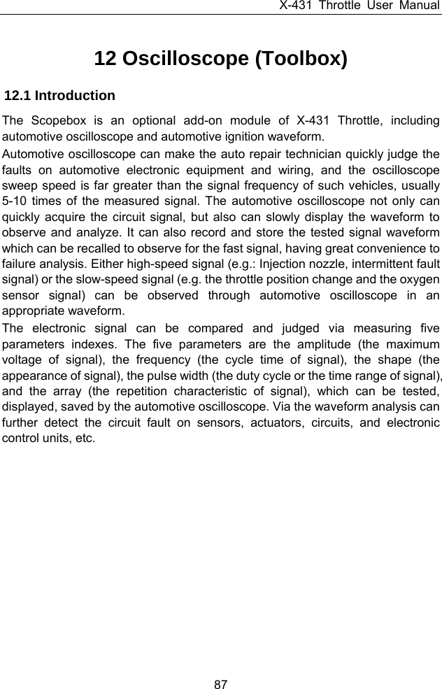
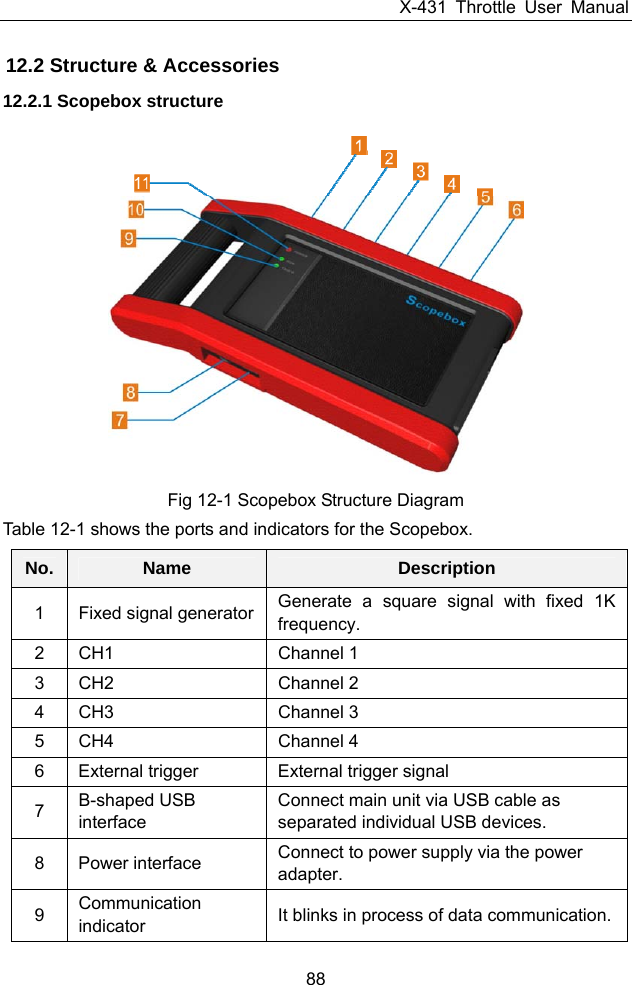
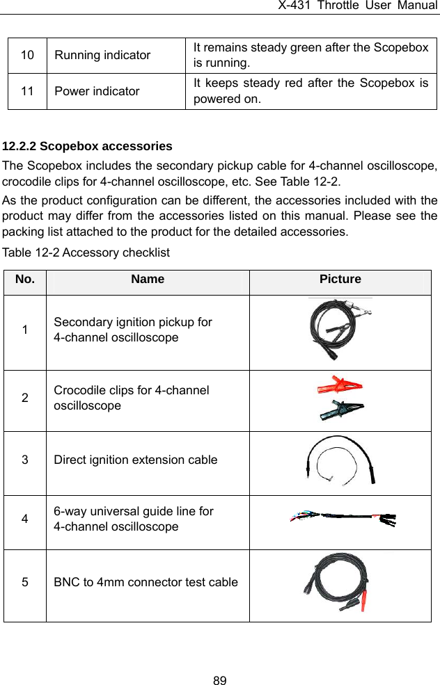
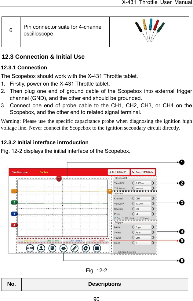
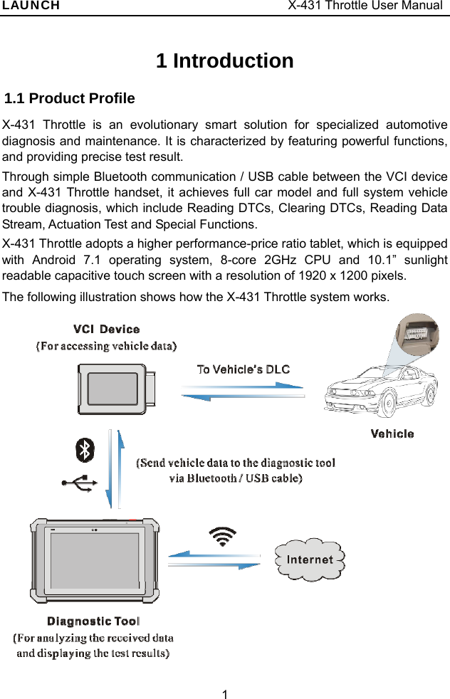
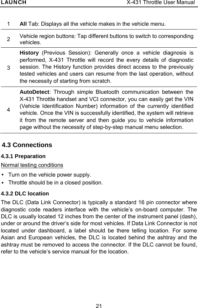
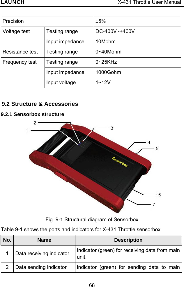
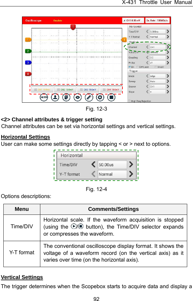
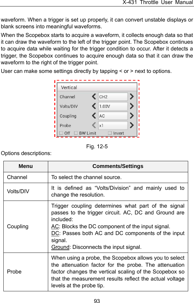
![X-431 Throttle User Manual 91 1 Signal display area 2 Horizontal Settings: Controls the time base. 3 Vertical Settings: Controls the amplitude of the displayed signal. 4 Trigger Settings: Controls the start event of the sweep. 5 Channel Selection Button 6 Function Menu [Auto]: It indicates auto trigger setting. [Ref]: There are expert reference and base reference available. Expert reference enables you to recall your customized expert database, whereas base reference provides automatic pre-setting function of specialized sensors. [File]: Provides save snapshot, snapshot manager, waveform record and waveform replay. [View]: Calibration and display settings are available. [Measure]: Includes signal source measurement, horizontal measurement, vertical measurement and clear measurement. [Settings]: Shows/hides the parameter settings area including horizontal settings, vertical settings and trigger settings. / [Start/Stop]: Starts/stops collecting waveforms. 12.4 Operations 12.4.1 Channel selection and attributes setting <1> Channel selection There are two ways available for channel selection: A. Select from the channel tab shown at the bottom of the waveform display area B. Select from Vertical settings Note: For better comparison and identification, each channel and waveform are marked in different colors.](https://usermanual.wiki/Launch-Tech/PADV/User-Guide-3967457-Page-101.png)
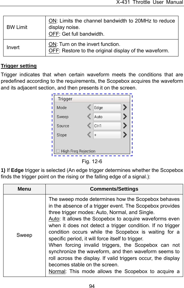
![X-431 Throttle User Manual 96 Condition To select pulse condition. Pulse Width Set required pulse width. High Freq Rejection Reject high frequency signals when selected. 12.4.2 Auto The Scopebox has an Auto feature that sets up the Scopebox automatically to display the input signal in a best fit. Tap , the Scopebox may change the current settings to display the signal. It automatically adjusts the vertical and horizontal scaling, as well as the trigger coupling, position, slope, level and mode settings. 12.4.3 View Settings <1> Calibration This option adjusts the Scopebox’s internal circuitry to get the best accuracy. Use this function to calibrate the Scopebox’s vertical and horizontal systems. Tap and then tap [Calibration], a dialog box similar to Fig. 12-7 will appear. Fig. 12-7 Check the box before the channel to select it. To deselect it, just uncheck it. After choosing the desired channel(s), tap [Start] to start calibration and [Start] button will be temporarily invalid during calibrating. Tap [Stop] to stop calibrating. Once](https://usermanual.wiki/Launch-Tech/PADV/User-Guide-3967457-Page-106.png)
![X-431 Throttle User Manual 97 it becomes active, it indicates calibration has completed. Note: In process of calibration, make sure CH1/CH2/CH3/CH4 has no signal input. Moreover, calibration may take several minutes and please be patient to wait. <2> REF settings Reference waveforms are saved waveforms to be selected for display. The reference function will be available after saving the selected waveform to non-volatile memory. Tap and then [REF] to enter the REF setting screen. Fig. 12-8 Tap < or > to select the desired reference value for time/DIV and volts/DIV. To show or hide the REF, just check/uncheck the box before On/Off. <3> Display settings Tap and then [Display settings] to enter the setting screen. Fig. 12-9 Select “Vectors” or “Dots” to display waveforms as vectors or dots. Check / uncheck the box before Grid to turn on/off grid display. 12.4.4 Measure <1> Channel source Tap and then [Source], a screen similar to Fig. 12-10 will appear.](https://usermanual.wiki/Launch-Tech/PADV/User-Guide-3967457-Page-107.png)
![X-431 Throttle User Manual 98 Fig. 12-10 <2> Horizontal / Vertical measure Horizontal Measure / Vertical Measure are used to measure voltage parameter and time parameter respectively. Drag A line upwards or downwards to control voltage. Move A line left or right to fine-tune timebase. A line is a solid line and B line is a dotted line. Tap and then [Horizontal Measure], a screen similar to Fig. 12-11 will appear. Fig. 12-11 Note: If no desired channel is selected, the system will take the current source as the default channel. <3> Clear measure Tap and then [Clear Measure], the system will clear the measurement result on screen.](https://usermanual.wiki/Launch-Tech/PADV/User-Guide-3967457-Page-108.png)
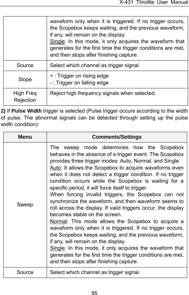
![X-431 Throttle User Manual 99 12.4.5 File management <1> Save snapshot While viewing sampling data, tap and then [Save Snapshot] to store the current screen. <2> Snapshot manager While viewing sampling data, tap and then [Snapshot Manager] to enter. View, delete and edit operations are supported. <3> Record waveform This function is used to record input waveforms that are acquired by the Scopebox at a specific period, and save it as waveform file which can be recalled in future. It can be performed only when the Scopebox is collecting data in Normal mode. Tap , then select [Record] from the pop-up menu to start recording. Fig. 12-12 Tap [Start] to start recording with a minimum record length of 10 frames, and [Stop] to stop recording. While recording, the recorded pages will be shown on the screen. <4> Load waveform for playback The Import function enables you to import the stored waveform file for playback and review. During replaying, the Scopebox stops collecting data automatically. Tap , then select [Waveform replay] from the pop-up menu to enter:](https://usermanual.wiki/Launch-Tech/PADV/User-Guide-3967457-Page-109.png)
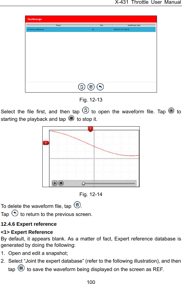
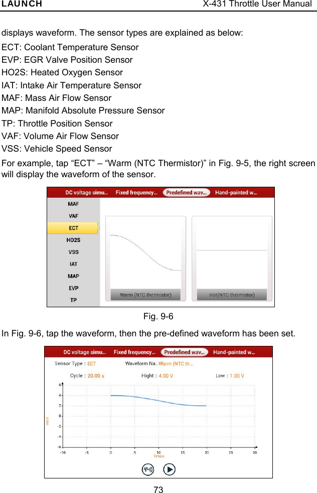
![X-431 Throttle User Manual 101 Fig. 12-15 Tap and then [Expert Reference] to enter, the following operation can be done: : To load and recall the selected file. : To delete the selected file. : To edit the selected file. <2> Base Reference Preset waveforms of some sensors are available for your reference. Fig. 12-16](https://usermanual.wiki/Launch-Tech/PADV/User-Guide-3967457-Page-111.png)