Launch Tech PADV Automotive intelligent diagnostic tools User Manual
Launch Tech Co., Ltd. Automotive intelligent diagnostic tools
User Manual
Version: V1.00.000
Revised date: 3-26-2018
Statement:
All information, specifications and illustrations in this manual are based on the
latest information available at the time of release. LAUNCH reserves the rights
to make changes at any time without notice.
User Manual

X-431 Throttle User Manual
i
Copyright Information
Copyright © 2018 by LAUNCH TECH. CO., LTD. All rights reserved. No part of
this publication may be reproduced, stored in a retrieval system, or transmitted
in any form or by any means, electronic, mechanical, photocopying, recording or
otherwise, without the prior written permission of LAUNCH. The information
contained herein is designed only for the use of this unit. LAUNCH is not
responsible for any use of this information as applied to other units.
Neither LAUNCH nor its affiliates shall be liable to the purchaser of this unit or
third parties for damages, losses, costs, or expenses incurred by purchaser or
third parties as a result of: Accident, misuse, or abuse of this unit, or
unauthorized modifications, repairs, or alterations to this unit, or failure to strictly
comply with LAUNCH operating and maintenance instructions. LAUNCH shall
not be liable for any damages or problems arising from the use of any options or
any consumable products other than those designated as Original LAUNCH
Products or LAUNCH Approved Products by LAUNCH.
Statement:LAUNCHownsthecompleteintellectualpropertyrightsforthesoftware
usedbythisproduct.Foranyreverseengineeringorcrackingactionsagainstthe
software,LAUNCHwillblocktheuseofthisproductandreservetherighttopursue
theirlegalliabilities.
Trademark Information
LAUNCH is a registered trademark of LAUNCH TECH CO., LTD. (LAUNCH) in
China and other countries. All other LAUNCH trademarks, service marks,
domain names, logos, and company names referred to in this manual are either
trademarks, registered trademarks, service marks, domain names, logos,
company names of or are otherwise the property of LAUNCH or its affiliates. In
countries where any of the LAUNCH trademarks, service marks, domain names,
logos and company names are not registered, LAUNCH claims other rights
associated with unregistered trademarks, service marks, domain names, logos,
and company names. Other products or company names referred to in this
manual may be trademarks of their respective owners. You may not use any
trademark, service mark, domain name, logo, or company name of LAUNCH or
any third party without permission from the owner of the applicable trademark,
service mark, domain name, logo, or company name. You may contact
LAUNCH at www.launchusa.com, or write to LAUNCH Tech (USA), Inc., 1820 S.
Milliken Ave. Ontario, CA 91761, to request written permission to use Materials
on this manual for purposes or for all other questions relating to this manual.

X-431 Throttle User Manual
ii
Important Safety Precautions
Important: To avoid personal injury, property damage, or accidental damage to
the product, read all of the information in this section before using the product.
y Never collide, throw, or puncture X-431 Throttle, and avoid falling, extruding
and bending it.
y Do not insert foreign objects into or place heavy objects on your device.
Sensitive components inside might cause damage.
y Do not use X-431 Throttle in exceptionally cold or hot, dusty, damp or dry
environments.
y In places using X-431 Throttle may cause interference or generate a potential
risk, please turn it off.
y X-431 Throttle is a sealed unit. There are no end-user serviceable parts
inside. All internal repairs must be done by an authorized repair facility or
qualified technician. If there is any inquiry, please contact the dealer.
y Never place X-431 Throttle into apparatus with strong electromagnetic field.
y Keep X-431 Throttle far away from magnetic devices because its radiations
can damage the screen and erase the data stored on X-431 Throttle.
y DANGER: Do not attempt to replace the internal rechargeable lithium battery.
Contact the dealer for factory replacement.
y CAUTION: Please use the included battery and charger. Risk of explosion if
the battery is replaced with an incorrect type.
y Do not disconnect power abruptly when X-431 Throttle is being formatted or
in process of uploading or downloading. Or else it may result in program
error.
y Do not delete unknown files or change the name of files or directories that
were not created by you, otherwise your X-431 Throttle software might fail to
work.
y Be aware that accessing network resources can leave your X-431 Throttle
vulnerable to computer viruses, hackers, spyware, and other malicious
activities that might damage your device, software or data. It is your
responsibility to ensure that you have adequate protection in the forms of
firewalls, antivirus software, and anti-spyware software and keep such
software up to date.

X-431 Throttle User Manual
iii
Precautions on Using X-431 Throttle
Before using this test equipment, please read the following safety information
carefully.
y Always perform automotive testing in a safe environment.
y If the diagnostic connector remains unused for a long period of time, it is
suggested to unplug the connector from vehicle’s DLC to conserve battery
power.
y Wear an ANSI-approved eye shield when testing or repairing vehicles.
y The vehicle shall be tested in a well-ventilated work area, as engines produce
various poisonous compounds (hydrocarbon, carbon monoxide, nitrogen
oxides, etc.)
y Do not connect or disconnect any test equipment while the ignition is on or
the engine is running.
y Put blocks in front of the drive wheels and never leave the vehicle unattended
while testing.
y Keep the test equipment dry, clean, free from oil, water or grease. Use a mild
detergent on a clean cloth to clear the outside of the equipment as
necessary.
y Do not drive the vehicle and operate the test equipment at the same time.
Any distraction may cause an accident.
y Keep clothing, hair, hands, tools, test equipment, etc. away from all moving or
hot engine parts.
y Before starting the engine, put the gear lever in the Neutral position (for
manual transmission) or in the Park (for automatic transmission) position to
avoid injury.
y To avoid damaging the test equipment or generating false data, please make
sure the vehicle battery is fully charged and the connection to the vehicle
DLC (Data Link Connector) is clear and secure.
y Automotive batteries contain sulfuric acid that is harmful to skin. In operation,
direct contact with the automotive batteries should be avoided. Keep the
ignition sources away from the battery at all times.
Precautions on Operating Vehicle’s ECU
y Do not disconnect battery or any wiring cables in the vehicle when the ignition
switch is on, as this could avoid damage to the sensors or the ECU.
y Do not place any magnetic objects near the ECU. Disconnect the power
supply to the ECU before performing any welding operations on the vehicle.

X-431 Throttle User Manual
iv
y Use extreme caution when performing any operations near the ECU or
sensors. Ground yourself when you disassemble PROM, otherwise ECU and
sensors can be damaged by static electricity.
y When reconnecting the ECU harness connector, be sure it is attached firmly,
otherwise electronic elements, such as ICs inside the ECU, can be damaged.

X-431 Throttle User Manual
v
TABLE OF CONTENTS
1 INTRODUCTION .............................................................................................. 1
1.1 PRODUCT PROFILE ..................................................................................... 1
1.2 FEATURES .................................................................................................. 2
1.3 TECHNICAL SPECIFICATIONS ....................................................................... 3
1.3.1 X-431 Throttle handset ...................................................................... 3
1.3.2 VCI connector .................................................................................... 3
2 KNOWLEDGE OF X-431 THROTTLE ............................................................. 5
2.1 X-431 THROTTLE TABLET ............................................................................ 5
2.1.1 Top view ............................................................................................. 5
2.1.2 Front view .......................................................................................... 6
2.1.3 Rear view ........................................................................................... 7
2.2 DOCKING STATION ...................................................................................... 8
2.3 VCI CONNECTOR ........................................................................................ 8
2.4 PACKAGE LIST .......................................................................................... 10
3 PREPARATIONS ........................................................................................... 11
3.1 CHARGING X-431 THROTTLE .................................................................... 11
3.2 USING YOUR BATTERY .............................................................................. 11
3.3 POWER ON/OFF ......................................................................................... 11
3.3.1 Power on .......................................................................................... 11
3.3.2 Power off .......................................................................................... 12
3.4 TIPS ON FINGER OPERATIONS ................................................................... 12
3.5 LOCK & UNLOCK SCREEN ......................................................................... 12
3.5.1 Lock the screen ............................................................................... 12
3.5.2 Unlock the screen ............................................................................ 13
3.6 SCREEN LAYOUT ....................................................................................... 13
3.7 ADJUST BRIGHTNESS ................................................................................ 13
3.8 SET STANDBY TIME ................................................................................... 13
3.9 CHANGING LANGUAGE .............................................................................. 14
3.10 WI-FI SETUP ........................................................................................... 14
3.9.1 Connect to a Wi-Fi network ............................................................. 14

X-431 Throttle User Manual
vi
3.9.2 Disconnect from a Wi-Fi network .................................................... 14
4 INITIAL USE ................................................................................................... 15
4.1 GETTING STARTED .................................................................................... 15
4.2 REGISTER & DOWNLOAD DIAGNOSTIC SOFTWARE ..................................... 15
4.2.1 User registration .............................................................................. 15
4.2.2 Function modules ............................................................................ 18
4.2.3 Vehicle menu layout ........................................................................ 20
4.3 CONNECTIONS .......................................................................................... 21
4.3.1 Preparation ...................................................................................... 21
4.3.2 DLC location .................................................................................... 21
4.3.3 Vehicle connection ........................................................................... 22
4.4 COMMUNICATION SETUP ........................................................................... 23
4.4.1 Pairing up via wireless (BT) communication ................................... 23
4.4.2 USB cable connection ..................................................................... 24
5 DIAGNOSIS ................................................................................................... 25
5.1 INTELLIGENT DIAGNOSIS (AUTODETECT) ................................................... 25
5.2 MANUAL DIAGNOSIS .................................................................................. 30
5.2.1 Health Report (Quick Test) .............................................................. 32
5.2.2 System Scan.................................................................................... 34
5.2.3 System Selection ............................................................................. 35
5.3 TECH TO TECH (REMOTE DIAGNOSIS) ....................................................... 42
5.3.1 Interface layout ................................................................................ 43
5.3.2 Add Friends...................................................................................... 43
5.3.3 Start instant messaging ................................................................... 45
5.3.4 Launch remote diagnosis (Device-To-Device) ................................ 46
5.3.5 Launch remote diagnosis (Device-To-PC) ...................................... 49
5.4 MANAGE REPORTS ................................................................................... 52
5.4.1 Health Report................................................................................... 52
5.4.2 Remote Report ................................................................................ 52
5.4.3 Playback .......................................................................................... 52
5.5 I/M READINESS ......................................................................................... 53
5.6 HOW TO VIEW DIAGNOSTIC HISTORY? ...................................................... 55

X-431 Throttle User Manual
vii
5.7 DIAGNOSTIC FEEDBACK ............................................................................ 55
5.8 VIEW REPAIR INFORMATION ...................................................................... 56
6 SOFTWARE UPDATE ................................................................................... 58
6.1 UPDATE DIAGNOSTIC SOFTWARE & APP................................................... 58
6.2 RENEW SOFTWARE SUBSCRIPTION ............................................................ 59
7 PROFILE ........................................................................................................ 60
7.1 PROFILE ................................................................................................... 60
7.2 EMAIL ....................................................................................................... 60
7.3 CHANGE PASSWORD ................................................................................. 60
7.4 FREE UPGRADE PERIOD ........................................................................... 60
7.5 ABOUT ...................................................................................................... 60
7.6 EXIT FROM CURRENT ACCOUNT ................................................................. 61
8 SETTINGS ...................................................................................................... 62
8.1 GENERAL .................................................................................................. 62
8.1.1 Units of Measurement ..................................................................... 62
81.2 Expiration Reminder ......................................................................... 62
8.1.3 Identifix Settings .............................................................................. 62
8.1.4 Auto Update ..................................................................................... 62
8.2 VCI ........................................................................................................... 62
8.3 VCI MANAGEMENT .................................................................................... 62
8.4 ACTIVATE VCI ........................................................................................... 63
8.5 FIRMWARE FIX .......................................................................................... 63
8.6 ICON SIZE ................................................................................................. 63
8.7 COLOR THEME .......................................................................................... 63
8.8 PRINTER SET ............................................................................................ 63
8.9 PRINT INFORMATION ................................................................................. 65
8.10 DATA STREAM SAMPLE ........................................................................... 65
8.11 VEHICLE VOLTAGE .................................................................................. 65
8.12 DIAGNOSTIC SOFTWARE CLEAR .............................................................. 65
8.13 BACKUP/RESTORE .................................................................................. 66
9 SENSORBOX (TOOLBOX) ........................................................................... 67

X-431 Throttle User Manual
viii
9.1 PRODUCT SUMMARY ................................................................................. 67
9.2 STRUCTURE & ACCESSORIES .................................................................... 68
9.2.1 Sensorbox structure ........................................................................ 68
9.2.2 Sensorbox accessories ................................................................... 69
9.3 SENSOR SIMULATION ................................................................................ 70
9.3.1 Connections ..................................................................................... 70
9.3.2 Simulation test ................................................................................. 70
9.3.3 Precautions on checking vehicle sensor ......................................... 74
10 MULTIMETER (TOOLBOX) ......................................................................... 76
10.1 MAIN MENU ............................................................................................ 76
10.2 TEST SAMPLE ......................................................................................... 77
11 BATTERYBOX (TOOLBOX) ........................................................................ 79
11.1 PRODUCT SUMMARY ............................................................................... 79
11.2 TEST ENVIRONMENT ............................................................................... 80
11.2.1 Test environment ............................................................................ 80
11.2.2 Battery status and description ....................................................... 80
11.3 BATTERYBOX STRUCTURE & ACCESSORIES ............................................ 81
11.3.1 Batterybox structure ....................................................................... 81
11.3.2 Test accessories ............................................................................ 81
11.4. CONNECTIONS & OPERATIONS ............................................................... 81
11.4.1 Connection ..................................................................................... 81
11.4.2 Inside the vehicle test .................................................................... 82
11.4.3 Outside the vehicle test ................................................................. 85
11.5 PRECAUTIONS ON BATTERY TEST ........................................................... 85
12 OSCILLOSCOPE (TOOLBOX) .................................................................... 87
12.1 INTRODUCTION ....................................................................................... 87
12.2 STRUCTURE & ACCESSORIES .................................................................. 88
12.2.1 Scopebox structure ........................................................................ 88
12.2.2 Scopebox accessories ................................................................... 89
12.3 CONNECTION & INITIAL USE .................................................................... 90
12.3.1 Connection..................................................................................... 90
12.3.2 Initial interface introduction ............................................................ 90

X-431 Throttle User Manual
ix
12.4 OPERATIONS .......................................................................................... 91
12.4.1 Channel selection and attributes setting ....................................... 91
12.4.2 Auto ................................................................................................ 96
12.4.3 View Settings ................................................................................. 96
12.4.4 Measure ......................................................................................... 97
12.4.5 File management ........................................................................... 99
12.4.6 Expert reference .......................................................................... 100
13 AUTOMOTIVE IGNITION WAVEFORM .................................................... 102
13.1 SECONDARY-DISTRIBUTOR IGNITION ANALYSIS ...................................... 102
13.2 SECONDARY-SIMULTANEOUS IGNITION ANALYSIS ................................... 104
13.3 SECONDARY-DIRECT IGNITION ANALYSIS ............................................... 106
13.4 WAVEFORM ANALYSIS MODE ................................................................. 107
14 OTHERS ..................................................................................................... 113
14.1 EMAIL ................................................................................................... 113
14.1.1 Configure an email account ......................................................... 113
14.1.2 Add an email account .................................................................. 113
14.2 BROWSER ............................................................................................. 113
14.2.1 Open browser .............................................................................. 113
14.2.2 Download files ............................................................................. 114
14.3 SYNCHRONIZATION ............................................................................... 114
14.3.1 Connect to PC ............................................................................. 114
14.3.2 Run on PC ................................................................................... 114
14.3.3 Install an application .................................................................... 115
14.4 CLEAR CACHE ...................................................................................... 115
15 FAQ ............................................................................................................ 116
LAUNCH X-431 Throttle User Manual
1
1 Introduction
1.1 Product Profile
X-431 Throttle is an evolutionary smart solution for specialized automotive
diagnosis and maintenance. It is characterized by featuring powerful functions,
and providing precise test result.
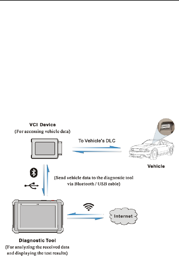
Through simple Bluetooth communication / USB cable between the VCI device
and X-431 Throttle handset, it achieves full car model and full system vehicle
trouble diagnosis, which include Reading DTCs, Clearing DTCs, Reading Data
Stream, Actuation Test and Special Functions.
X-431 Throttle adopts a higher performance-price ratio tablet, which is equipped
with Android 7.1 operating system, 8-core 2GHz CPU and 10.1” sunlight
readable capacitive touch screen with a resolution of 1920 x 1200 pixels.
The following illustration shows how the X-431 Throttle system works.

LAUNCH X-431 Throttle User Manual
2
1.2 Features
1. Diagnose:
y Smart Diagnosis (AutoDetect): This module allows you to use the VIN
information of the currently identified vehicle to access its data (including
vehicle information, historical diagnostic records) from the cloud server to
perform quick test.
y Local Diagnosis: To perform diagnosis by executing on-screen commands
step by step. Diagnosis functions include: Read DTCs, Clear DTCs, Read
Data Stream, Special Functions etc.
y I/M Readiness: I/M refers to Inspection and Maintenance that is legislated by
the Government to meet federal clean-air standards. I/M Readiness indicates
whether or not the various emissions-related systems on the vehicle are
operating properly and are ready for Inspection and Maintenance testing.
y Tech-To-Tech: This option aims to help repair shops or technicians launch
instant messaging and remote diagnosis, making the repair job getting fixed
faster.
y Maintenance & Reset: All kinds of common maintenance and reset items
including Oil lamp reset, DPF regeneration, ABS bleeding etc. can be done.
y Diagnostic History: Provides a quick access to the tested vehicles and users
can choose to view the test report or resume from previous diagnostic session,
without the necessity of starting from scratch.
y Pre- and Post- Repair Result Comparison: By comparing the pre-repair and
post-repair report, you can clearly determine which vehicle issues have been
fixed and which remained unsolved.
y One-click Update: Lets you update your diagnostic software online.
y Diagnostic feedback: Enables you to submit the vehicle issue to us for
analysis and troubleshooting.
y Repair Info: Multiple speed dial to professional repair website are available for
helping repair professionals diagnose and repair vehicle efficiently, accurately
and profitably.
y Vehicle Coverage: Enables you to quickly check which vehicle models are
supported.
y Backup/Restore: This feature lets you back up the recorded files to external
storage device/restore the recorded data from external storage device.
y Add-on Modules: Scopebox, Sensorbox, Batterybox and Videoscope (sold
separately) are available for extending the functions of X-431 Throttle.

LAUNCH X-431 Throttle User Manual
3
2. Compatible with Wi-Fi projecting technology: To mirror your X-431 Throttle
screen onto an external projector or monitor with HD I/O interface via wireless
technology.
3. Web browser: Users can make online search and visit any website.
1.3 Technical Specifications
1.3.1 X-431 Throttle handset
Operating system Android 7.1
Processor 8-core 2GHz processor
Battery 9000mAh rechargeable polymer lithium battery
Charging via 5V DC power supply
Memory 4GB
Storage 64GB
Screen 10.1 inch capacitive touch screen with a resolution of
1920 x 1200 pixels
Camera Front-facing 8.0MP camera + rear-facing 13MP
camera
Connectivity
y WLAN (802.11b/g/n/ac)
y Universal serial BUS Ports (1 x Type-C + 1 x
Type-A)
y Bluetooth 2.1 & 2.4
Sensor y Gravity Accelerometer
y 3-Axis Acceleration Sensor
Working temperature -10℃ ~ 50℃(14 ~122℉)
Storage temperature -20℃ ~ 70℃(-4 ~158℉)
1.3.2 VCI connector
Working voltage DC 9 ~18V
Average working current About 35mA

LAUNCH X-431 Throttle User Manual
4
Standby current About 25mA
Working temperature -20℃ to 55℃(-4 ~131℉)
Storage temperature -30℃ to 70℃(-22~158℉)
LAUNCH X-431 Throttle User Manual
5
2 Knowledge of X-431 Throttle
There are three main components to the X-431 Throttle system:
y X-431 Throttle tablet – the central processor and monitor for the system (See
Chapter “2.1”)
y Docking Station – the platform for charging X-431 Throttle tablet and
extending functions (For details, please refer to Chapter 2.2.)
y VCI device – the device for accessing vehicle data (See Chapter “2.3”)
2.1 X-431 Throttle tablet
The handset acts as the central processing system, which is used to receive and
analyze the live vehicle data from the VCI connector and then output the test
result.
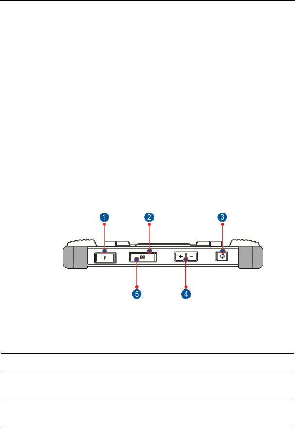
2.1.1 Top view
Fig. 2-1
1 Memory Card Slot To store the memory card for storage
expansion.
2 Charging Po
r
t Reserved for charging the handset.
3 Power/Screen
Lock Button
To turn the handset on/off with long press, or
lock the screen with short press.
4 Volume Buttons To adjust the volume.
*Note: Press and hold [POWER] and [VOL -] key to
LAUNCH X-431 Throttle User Manual
6
capture the current screenshot.
5 Data
Transmission Port
Reserved for add-on modules (such as
Batterybox, Scopebox and Sensorbox), and
other devices with similar port.
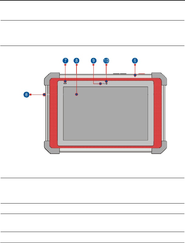
2.1.2 Front view
Fig. 2-2
6 Microphone To adjust the volume.
7 Charging indicator
It illuminates red while the handset is charging.
Once charging is finished, it will illuminate solid
green.
8 Touch Screen
9 Ambient Light
Sensor
10 Front Camera
LAUNCH X-431 Throttle User Manual
7
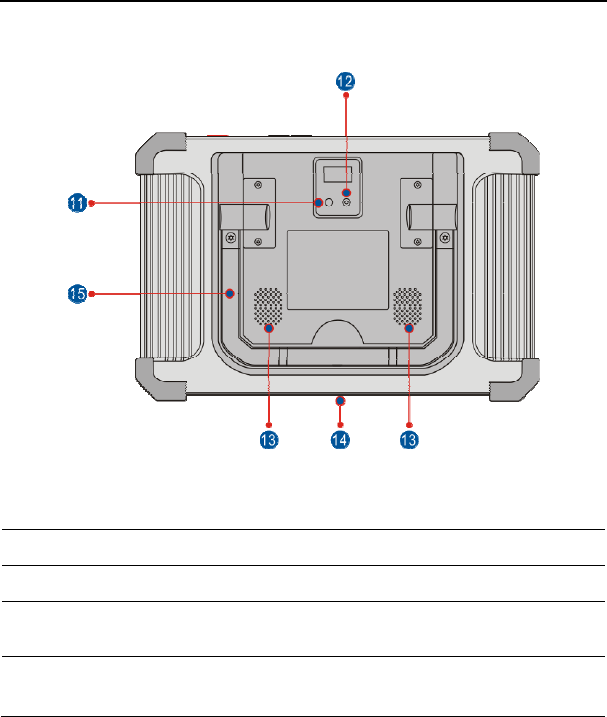
2.1.3 Rear view
Fig. 2-3
11 Rear Camera
12 Camera Flash
13 Audio Speake
r
14 Charging Slot Align it with the charging slot on the docking
station to charge the handset.
15 Adjustable
Kickstand
Flip out it to any angle and work comfortable at
your desk, or hang it on automotive part.
LAUNCH X-431 Throttle User Manual
8
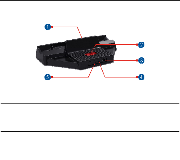
2.2 Docking Station
Fig. 2-4
1 Charging Slot
2 OBD16 Socket To store the VCI device to avoid loss.
3 Data
Transmission Port
Reserved for add-on modules, and other
devices with similar port.
4 Charging Port Use the power adaptor to supply power to the
docking station through connection to AC outlet.
5 Power LED Illuminates solid green when it is powered up.
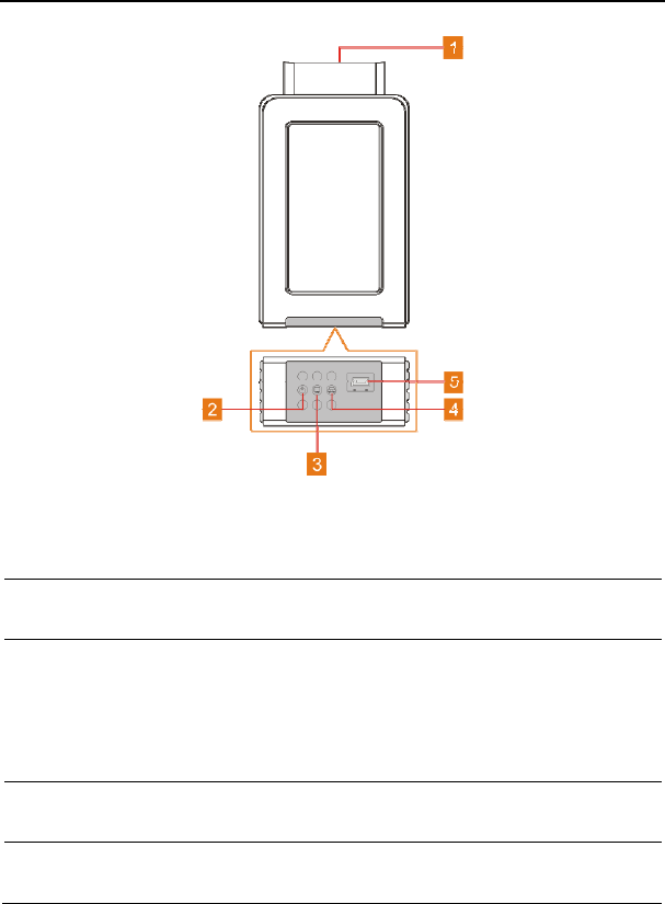
2.3 VCI Connector
The VCI connector works as a vehicle communication interface device, which is
used to connect to the vehicle’s DLC (Data Link Connector) socket directly or via
OBD II extension cable to read the vehicle data and then send it to the X-431
Throttle handset via wireless communication technology.
LAUNCH X-431 Throttle User Manual
9
Fig. 2-5 VCI connector
1 OBD-16 diagnostic
connector To connect on vehicle’s OBD II DLC.
2 Power indicator It lights up while the connector is plugged into
the vehicle’s DLC.
3
Wireless (BT)/data
cable
communication
indicator
y It indicates wireless (BT) communication
mode if the VCI is energized and illuminates
blue (default mode).
y It illuminates red when the VCI is connected to
the diagnostic tool via data cable.
4 ECU communication
indicator
It flashes when the VCI is communicating with
the vehicle.
5 Data Transmission
port
To connect to the handset to perform vehicle
diagnosis via data cable.

LAUNCH X-431 Throttle User Manual
10
2.4 Package List
For different product configurations, the accessories may vary. For detailed
accessory items, please consult from the local agency or check the package list
supplied with X-431 Throttle together.
No. Item Descriptions Qt.
1 X-431 Throttle
handset Indicates the test result. 1
2 Docking station To dock or charge the handset. 1
3 VCI device Collects the vehicle data and sends it
to the handset for analysis. 1
4 OBD II extension
cable
To connect the VCI device to the OBD
II vehicle’s DLC. 1
5 Power adaptor To charge the handset. 1
6 OBD I adaptor An adaptor cable for connecting
non-16 pin connector. 1
7 Cigarette lighter
cable
To supply power to the non-16pin
connector from the vehicle’s cigarette
lighter receptacle.
1
8 Battery clamps
cable
To supply power to the non-16pin
connector through connection to the
vehicle’s battery.
1
9 Password envelope
A piece of paper bearing the product
Serial Number and Activation Code for
product registration.
1
10 Non-16pin adaptor
cable kit
To connect to the vehicle equipped
with non-OBD II management system. (Optional)

LAUNCH X-431 Throttle User Manual
11
3 Preparations
3.1 Charging X-431 Throttle
Choose any of the followings to charge your handset:
A. Use the included 5V power adaptor: Connect one end of the power adaptor to
Type C charging port of the handset, and the other end to the AC outlet.
Never use other similar adaptors to charge it.
B. Use the docking station: Follow the steps described as below to charge your
handset:
1. Locate the charging slot on the bottom of the handset and docking station.
2. Align the charging slots, and then dock the tablet into the station to ensure
that it is firmly seated on the docking station.
3. Insert one end of the included power cord to the charging port of the docking
station, then the other end into the AC outlet. The charging LED illuminates
solid red while charging.
4. Once it illuminates solid green, it indicates that the battery is fully charged.
Disconnect the docking station from the AC outlet.
3.2 Using Your Battery
If the battery remains unused for a long period of time or the battery is
completely discharged, it is normal that the tool will not power on while being
charged. Please charge it for a period of 5 minutes and then turn it on.
Please use the included power adaptor to charge your tool. No responsibility
can be assumed for any damage or loss caused as a result of using power
adaptors other than the one supplied.
While X-431 Throttle has low battery, a beep will sound. If it is very low, X-431
Throttle will be switched off automatically.
3.3 Power on/off
3.3.1 Power on
Press [POWER] to turn the tool on.
*Note: If it is the first time you have used this tool or the tool remains idle for a long
period of time, the tool could fail to turn on. Please charge the tool for a minimum of 5
LAUNCH X-431 Throttle User Manual
12
minutes and attempt to turn on again.
3.3.2 Power off
Press [POWER] for 3 seconds, an option menu will pop up on the screen. Tap
“Power off” to turn the tool off.
To perform a forced shutdown, press [POWER] for more than 8 seconds until
the screen goes dark.
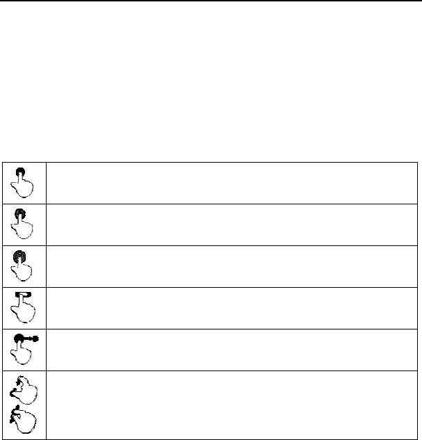
3.4 Tips on Finger Operations
Single-tap: To select a item or launch a program.
Double-tap: To zoom in so that the text on a webpage appears in a
column that fits your device’s screen.
Long press: Tap and hold on the current interface or area until a
contextual menu pops up on the screen, and then release it.
Slide: To jump to different pages.
Drag: Tap the desktop icon and drop it to other location.
Spread apart/pinch together: To zoom in manually, place two
fingers on the screen and then spread them apart. To zoom out,
place two fingers apart on the screen and then pinch them together.
3.5 Lock & Unlock Screen
Many screen lock modes are available on X-431 Throttle.
*Note: You are recommended to set screen lock as “None” since X-431 Throttle is a
frequently used diagnostic tool.
3.5.1 Lock the screen
When it is ON, press [POWER] once to lock the screen;
The system will lock the screen automatically after X-431 Throttle remains
idle over the preset standby time.
LAUNCH X-431 Throttle User Manual
13
3.5.2 Unlock the screen
Press [POWER] to activate the screen and drag the lock to “Unlock” position.
*Note: If you define as unlock using the pattern, you have to draw the right target
pattern to unlock it.
3.6 Screen Layout
1. Preview the screen
Tap and hold any blank area on the home screen, a function menu will pop up at
the bottom of the screen. It mainly includes wallpapers, lock screen wallpapers,
widgets, settings and apps.
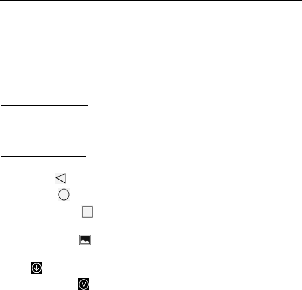
2. On-screen buttons
There are 6 on-screen buttons available on the bottom of the screen.
y Back: Tap to return to the previous screen.
y Home: Tap to jump to the Android’s home screen.
y Recent App: Tap to view the recently launched applications and running
applications.
y Screenshot: Tap to capture the current screen.
y Downloadable: Once some upgradable diagnostic software is detected, the
icon will turn highlighted.
y VCI Connection : Shows whether the VCI device is properly connected or
not.
3.7 Adjust Brightness
Tips: Reducing the brightness of the screen is helpful to save the power of X-431
Throttle.
1. On the home screen, tap Settings -> Display -> Brightness level.
2. Drag the slider to adjust it.
3.8 Set Standby Time
If no activities are made within the defined standby period, the screen will be
locked automatically and the system enters sleep mode to save power.

LAUNCH X-431 Throttle User Manual
14
1. On the home screen, tap Settings -> Display -> Sleep.
2. Choose the desired sleep time.
3.9 Changing Language
X-431 Throttle supports multiple languages.
To change the language of the handset, please do the following:
1. On the home screen, tap Settings -> Language & Input -> Languages.
2. Tap “Add a language”, and then choose the desired language from the list.
3. Tap and hold the desired language and drag it to the top of the screen and
then release it, the system will change into the target language.
3.10 Wi-Fi Setup
Note: Once WLAN is set as ON, X-431 Throttle will consume more power. While
WLAN keeps unused, please turn it off to conserve battery power.
X-431 Throttle has a built-in Wi-Fi module that can be used to get online. Once
you’re online, you can register your X-431 Throttle, update the diagnostic
software & APK, surf the Internet, get apps and send email on your network.
3.9.1 Connect to a Wi-Fi network
1. On the home screen, tap Settings -> WLAN.
2. Tap or slide the Wi-Fi switch to ON, X-431 Throttle starts searching for all
available wireless LANs.
3. Choose the desired Wi-Fi access point / network,
y If the network you chose is open, you can connect directly;
y If the selected network is encrypted, you have to enter the right security
key (network password).
Once it is connected successfully, tap the Wi-Fi network from the list to view its
name, link speed, security type, IP address etc.
3.9.2 Disconnect from a Wi-Fi network
1. On the home screen, tap Settings -> WLAN.
2. Tap the network with a Connected status, then tap “Disconnect”.
LAUNCH X-431 Throttle User Manual
15
4 Initial Use
4.1 Getting Started
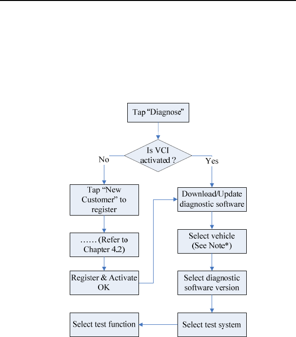
For new users, please follow the operation chart shown in Fig. 4-1 to start using
X-431 Throttle.
Fig. 4-1
Note*: If “VIN Scan” function is performed, this step shall not apply.
4.2 Register & Download Diagnostic Software
4.2.1 User registration
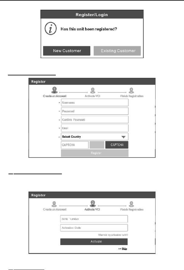
On the home screen, tap the application icon to launch it, a dialog box similar to
the following will pop up on the screen:
LAUNCH X-431 Throttle User Manual
16
Fig. 4-2
A. If you are a new user, tap “New Customer” in Fig. 4-2 to start your sign-up.
Fig. 4-3
a) Create App Account: In Fig. 4-3, fill in the information in each field (Items
with * must be filled). After inputting, tap “Register”, a screen similar to the
following will appear:
Fig. 4-4
b) Activate VCI: In Fig. 4-4, input the Serial Number and Activation Code,
LAUNCH X-431 Throttle User Manual
17
which can be found in the password envelope.
Fig. 4-5
Note: To exit and activate it later, tap “Skip”. In this case, you can activate it by
tapping “Activate VCI” in “Settings”.
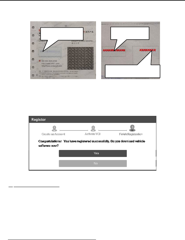
Tap “Activate” to finish your registration. See Fig. 4-6.
Fig. 4-6
c) Finish Registration: To download the diagnostic software, tap “Yes” to
navigate to the download page. Tap “No” to download and install it later.
On the download page, tap “Update” to start downloading. To pause
downloading, tap “Stop”. To resume it, tap “Continue”. Once download is
complete, the system will install the software package automatically.
Note: In process of download, please make sure the tablet has a strong Wi-Fi
signal. It may take several minutes to finish it, please be patient to wait.
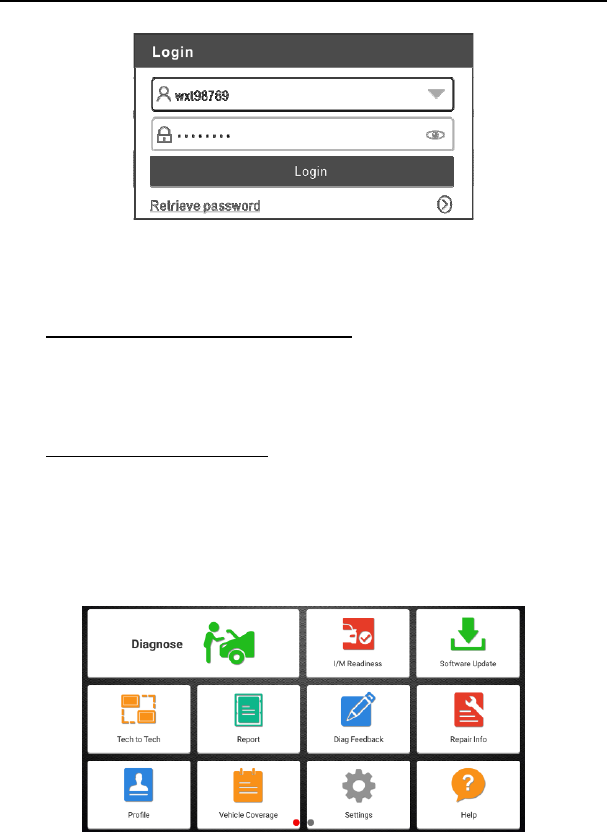
B. If you have registered to be a member, tap “Existing Customer” in Fig. 4-2, a
screen similar to the following appears:
Product SN
Activation code
Product SN
LAUNCH X-431 Throttle User Manual
18
Fig. 4-7
(If you have registered to be a member, go to a) to login the system directly.)
(In case you forgot password, refer to b) to reset a new password.)
a) If you have registered to be a member, input your name and password,
and then tap the “Login” button to enter the main menu screen directly.
Note: The X-431 Throttle has an auto-save function. Once the username and
password are correctly entered, the system will automatically store it. Next time
you login the system, you will not be asked to input the account manually.
b) If you forgot the password, tap “Retrieve password” and then follow
on-screen instructions to set a new password.
4.2.2 Function modules
There are two function modules available on the X-431 Throttle: Diagnostics
and Toolbox. Swipe the screen in from left/right to toggle between them.
Diagnostics mainly includes the following items:
Fig. 4-8

LAUNCH X-431 Throttle User Manual
19
Name Description
Diagnose To configures X-431 Throttle to operate as a diagnostic
tool.
I/M Readiness
I/M Readiness indicates whether or not the various
emissions-related systems on the vehicle are operating
properly and are ready for Inspection and Maintenance
testing.
Software Upgrade To update vehicle diagnostic software and APK.
Tech-To-Tech
This option aims to help repair shops or technicians
launch instant messaging and remote diagnosis,
making the repair job getting fixed faster.
Reports To manage saved diagnostic reports and records.
Diag. Feedback To feed back the recent 20 diagnostic logs to us for
issue analysis.
Repair Info Provides quick access to various authorized automotive
repair database.
Profile To manage personal information.
Vehicle Coverage To view all the vehicle models that the X-431 Throttle
covers.
Diagnostic History
Generally once a vehicle diagnosis is performed, X-431
Throttle will automatically record every details of
diagnostic session. This function provides a quick
access to the tested vehicles and users can resume
from the last operation, without the necessity of starting
from scratch.
Settings
To make some general system settings, activate VCI,
configure printer and print information, clear diagnostic
software and backup/restore etc.
Help Includes FAQ, Quick Start Guide and User Manual.
LAUNCH X-431 Throttle User Manual
20
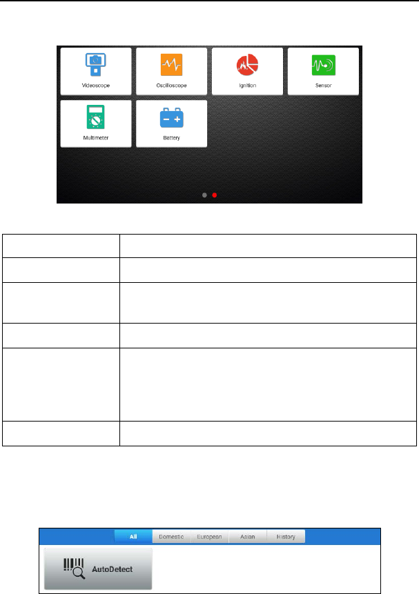
Toolbox mainly includes the following add-on modules:
Fig. 4-9
Name Description
Videoscope To check unseen or unreachable parts or components.
Oscilloscope/
Ignition
To determine vehicle electrical equipment and circuit
trouble.
Sensor To diagnose/simulate vehicle ECU sensor trouble.
Multimeter
To measure physical parameters such as voltage,
resistance, frequency etc.
*Note: The function utilizes the same hardware device as the
sensor module.
Battery To test whether vehicle's battery is good or not.
4.2.3 Vehicle menu layout
After downloading the diagnostic software, you can go to “Diagnose” to check if
all software are completely downloaded and installed.
Tap “Diagnose”, a screen similar to the following figure appears:
Fig. 4-10

LAUNCH X-431 Throttle User Manual
21
1 All Tab: Displays all the vehicle makes in the vehicle menu.
2 Vehicle region buttons: Tap different buttons to switch to corresponding
vehicles.
3
History (Previous Session): Generally once a vehicle diagnosis is
performed, X-431 Throttle will record the every details of diagnostic
session. The History function provides direct access to the previously
tested vehicles and users can resume from the last operation, without
the necessity of starting from scratch.
4
AutoDetect: Through simple Bluetooth communication between the
X-431 Throttle handset and VCI connector, you can easily get the VIN
(Vehicle Identification Number) information of the currently identified
vehicle. Once the VIN is successfully identified, the system will retrieve
it from the remote server and then guide you to vehicle information
page without the necessity of step-by-step manual menu selection.
4.3 Connections
4.3.1 Preparation
Normal testing conditions
y Turn on the vehicle power supply.
y Throttle should be in a closed position.
4.3.2 DLC location
The DLC (Data Link Connector) is typically a standard 16 pin connector where
diagnostic code readers interface with the vehicle’s on-board computer. The
DLC is usually located 12 inches from the center of the instrument panel (dash),
under or around the driver’s side for most vehicles. If Data Link Connector is not
located under dashboard, a label should be there telling location. For some
Asian and European vehicles, the DLC is located behind the ashtray and the
ashtray must be removed to access the connector. If the DLC cannot be found,
refer to the vehicle’s service manual for the location.

LAUNCH X-431 Throttle User Manual
22
Fig. 4-11
4.3.3 Vehicle connection
The method used to connect the diagnostic connector to a vehicle’s DLC
depends on the vehicle’s configuration as follows:
y A vehicle equipped with an OBD II management system supplies both
communication and 12V power through a standardized DLC.
y A vehicle not equipped with an OBD II management system supplies
communication through a DLC connection, and in some cases supplies 12V
power through the cigarette lighter receptacle or a connection to the vehicle
battery.
Follow the steps mentioned below to connect OBD II vehicle:
1. Locate vehicle’s DLC socket.
2. Plug the VCI connector into the vehicle’s DLC socket (It is suggested to use
the OBD II extension cable to connect the VCI connector and DLC socket.).
3. Choose one of the two ways to obtain power from:
A. Power adaptor: Connect one end of the included power adaptor to DC IN
port of X-431 Throttle tablet, and the other end to AC outlet.
B. Internal battery pack
For non-OBDII vehicle, proceed as follows:
1. Locate vehicle’s DLC socket.
2. Select the corresponding non-16pin connector.
3. Plug the non-16pin end of the connector into the DLC socket, and the other
end to the OBD I adaptor, and then tighten the captive screws.
4. Connect the other end of the adaptor to the included VCI connector.
5. To supply power to OBD I adaptor from:
A. Cigarette Lighter Cable: Connect one end of the cigarette lighter cable to
vehicle’s cigarette lighter receptacle, and the other end to the power jack of
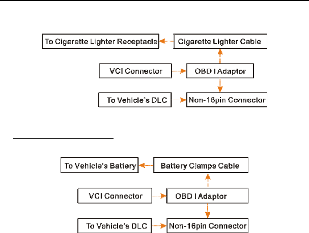
LAUNCH X-431 Throttle User Manual
23
OBD I adaptor.
Fig. 4-12
B. Battery Clamps Cable: Connect one end of the battery clamps cable to
vehicle’s battery, and the other end to the power jack of OBD I adaptor.
Fig. 4-13
4.4 Communication Setup
There are two kinds of ways available for X-431 Throttle to pair with the VCI
device.
4.4.1 Pairing up via wireless (BT) communication
1. Connect one end of the USB cable (optional) to the Mini USB port of the VCI
device.
2. Connect the other end to the USB port of the PC. The power indicator of the
VCI lights up.
3. Enter Bluetooth setting screen by tapping “Settings” -> “Bluetooth”, slide the
Bluetooth switch to ON and X-431 Throttle starts searching for all available
Bluetooth device.
4. Tap the desired VCI to pair and match. By default, the Bluetooth ID of the VCI
is 98********00 (where ******** stands for 8 digits).
5. If the Bluetooth pair request pops up on the screen, enter the request pin
code (default code: 0000 or 1234).

LAUNCH X-431 Throttle User Manual
24
6. Once the VCI is paired with the handset, it will be shown under the paired
device tab.
Note: In case no Bluetooth setting is done before diagnostic software is launched, you
can also configure it in process of vehicle diagnosis.
4.4.2 USB cable connection
The USB cable connection is a simple & quick way to establish communication
between the handset and the VCI device. After properly connecting the USB
cable from the handset to the VCI, the VCI navigation button at the bottom of the
screen becomes highlighted, indicating the USB connection is successful.
*Note: The USB connection provides the most stable and fastest communication. When
all communication methods are applied at the same time, the X-431 Throttle system
will use the USB communication as the default priority.

LAUNCH X-431 Throttle User Manual
25
5 Diagnosis
X-431 Throttle supports two kinds of diagnosis methods: Smart Diagnosis
(AutoDetect) and Manual Diagnosis.
5.1 Intelligent Diagnosis (AutoDetect)
Through simple Bluetooth communication between the X-431 Throttle handset
and VCI device, you can easily get the VIN (Vehicle Identification Number)
information of the currently identified vehicle. Once the VIN is successfully
identified, the system will retrieve it from the remote server and then guide you to
vehicle information page without the necessity of step-by-step manual menu
selection.
The vehicle information page lists all historical diagnostic records of the vehicle,
which lets the technician have a total command of the vehicle faults. In addition,
a quick dial to local diagnosis and diagnostic function are also available on this
page for reducing the roundabout time and increasing productivity.
Notes:
• Before using this function, please make sure the VCI device is properly connected to
the vehicle’s DLC. For detailed connection, see Chapter 4.3.3 “Vehicle
Connection”.
• A stable network connection is required for this function.
Follow the steps below to proceed.
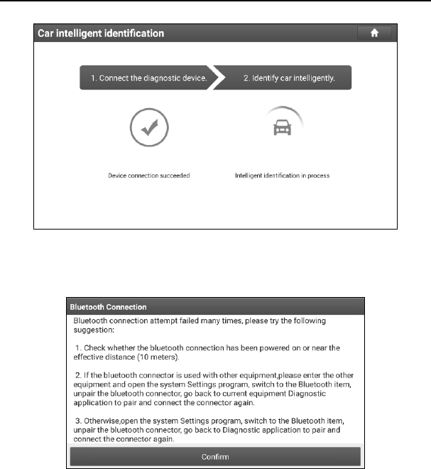
1. Tap “Diagnose” on the Diagnostics function module and tap “AutoDetect” to
enter Fig. 5-1.
LAUNCH X-431 Throttle User Manual
26
Fig. 5-1
Note: If the VCI connector is not paired up with the X-431 Throttle handset before
doing this step, a prompt message box will appear:
Fig. 5-2
Check all the possible reasons of Bluetooth connection failure carefully, and then tap
“Confirm”.
LAUNCH X-431 Throttle User Manual
27
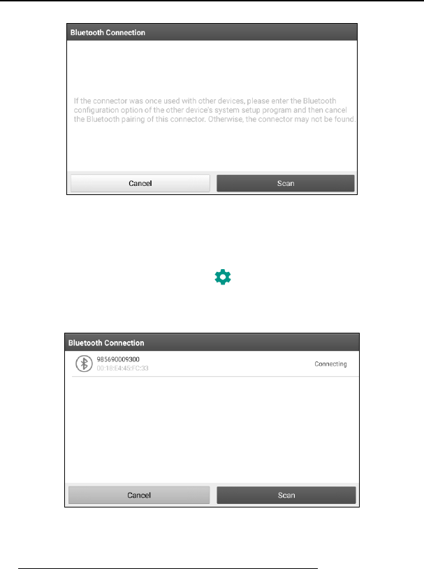
Fig. 5-3
If the VCI connector was once used with other devices, you need to cancel the pairing
of the connector first via either one of the following ways:
• On the Android’s home screen, tap “Settings” -> “Bluetooth” -> Choose the desired
VCI connector from the Paired list. Tap “ ”, and then tap “FORGET” to unpair it.
• Tap “Settings” -> “VCI Management” -> Tap “Deactivate matching”.
Tap “Scan” to start searching for the VCI connector and pairing up with it.
Fig. 5-4
2. Once pairing is complete, the handset starts reading the vehicle VIN.
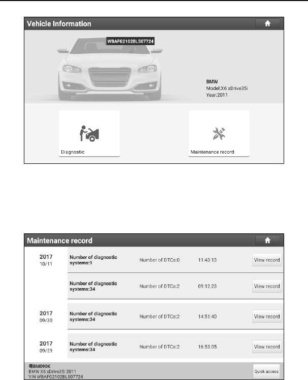
A. If the VIN can be found from the remote server database, a screen similar to
Fig. 5-5 displays:
LAUNCH X-431 Throttle User Manual
28
Fig. 5-5
• Tap “Diagnostic” to start a new diagnostic session.
• Tap “Maintenance record” to view its historical repair record. If there are
records available, it will be listed on the screen in sequence of date. If no
records exist, the screen will show “No Record”.
Fig. 5-6
• Tap “View record” to view the details of the current diagnostic report.
• To perform other functions, tap “Quick access” to directly go to the function
selection screen. Choose the desired one to start a new diagnostic
session.
LAUNCH X-431 Throttle User Manual
29
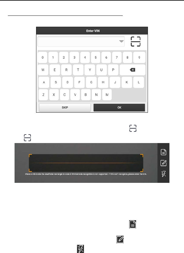
B. If the handset failed to access the VIN information, the screen will display as
below:
Fig. 5-7
In this mode, you need to input the VIN manually or tap to scan it.
1) Tap “ ” to launch the VIN recognition module.
Fig. 5-8
Place the VIN inside the viewfinder rectangle to scan it. The most
recognizable location for this number is in the top left corner on the
vehicle’s dashboard. Other locations include the driver’s door or post, and
the firewall under the hood.
• If you have scanned the VIN of the vehicle, tap to choose it from
the record list.
• In case the handset failed to detect it, tap to enter it manually.
• To turn the flash on, tap .
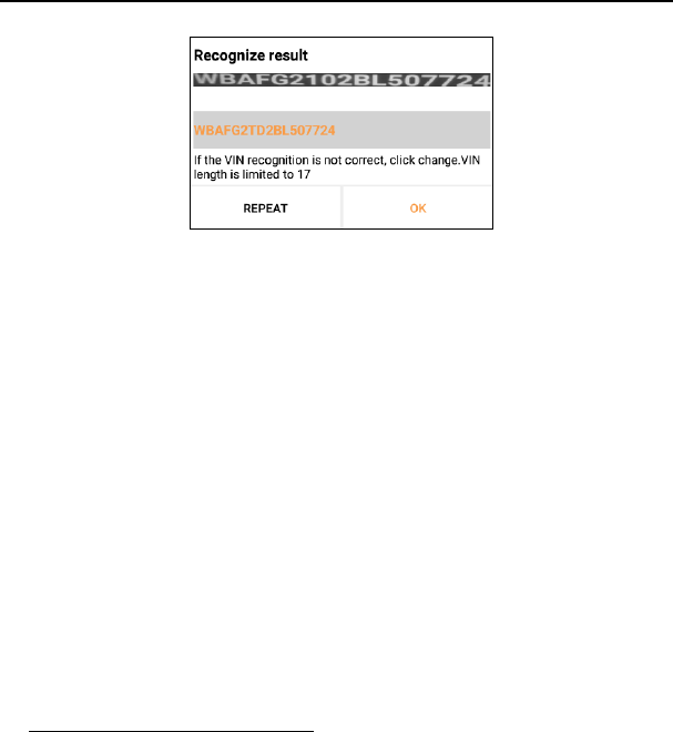
After scanning, the screen automatically displays the result.
LAUNCH X-431 Throttle User Manual
30
Fig. 5-9
• If the VIN scanned is incorrect, tap the result field to modify it and then
tap “OK”. If the VIN exists on the remote server, the system will enter
the vehicle information screen. See Fig. 5-5.
• To scan it again, tap “REPEAT”.
2) Input the VIN, and tap “OK”, the system will automatically identify the
vehicle model and directly navigate to the vehicle information page.
In general, vehicle identification numbers are standardized - all contain 17
characters. VIN characters may be capital letters A through Z and numbers
1 through 0; however, the letters I, O and Q are never used in order to avoid
mistakes of misreading. No signs or spaces are allowed in the VIN.
Tap “SKIP” to go to Diagnostics main menu screen.
5.2 Manual Diagnosis
In this mode, you need to execute the menu-driven command and then follow
the on-screen instruction to proceed.
Take Demo as an example to demonstrate how to diagnose a vehicle.
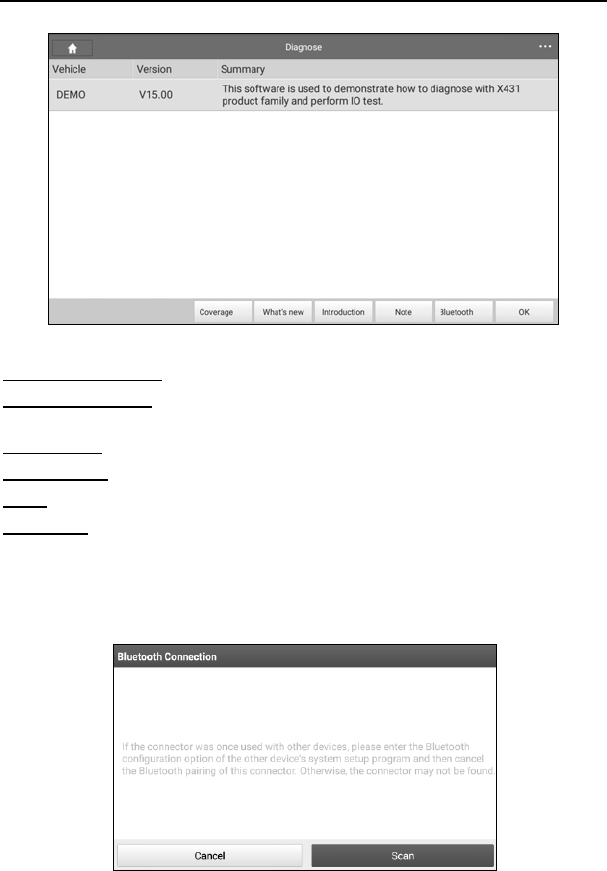
1). Select diagnostic software version: Tap the “DEMO” to go to Step 2. (Note: If
more than one version is available on this handset, it will be listed on the screen.)
LAUNCH X-431 Throttle User Manual
31
Fig. 5-10
On-screen Buttons:
Vehicle Coverage: Tap to view the vehicle models that the current diagnostic
software covers.
What’s new: Tap to view the optimized items and enhancements.
Introduction: Tap to check the software function list.
Note: Tap to read some precautions on using the current diagnostic software.
Bluetooth: Tap to search for the available VCI Bluetooth connector.
Notes:
• No Bluetooth connection is required for DEMO program.
• If a vehicle is tested and no Bluetooth connection is made before diagnosis, tap
“Search Bluetooth”, a dialog box similar to the following appears:
LAUNCH X-431 Throttle User Manual
32
Fig. 5-11
Tap “Scan” to start searching for the VCI device. Once it is found, tap it to start pairing.
If the X-431 Torque handset has paired with the VCI device, it will enter Step 2
directly.
OK: Tap it to go to next step.
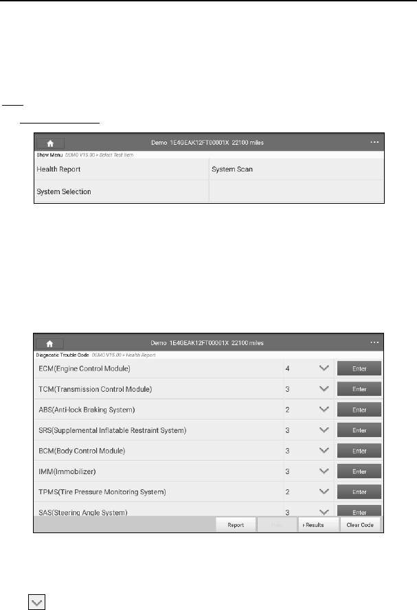
2). Select test item: Select the desired test item to proceed.
Fig. 5-12
5.2.1 Health Report (Quick Test)
This function varies from vehicle to vehicle. It enables you to quickly access all
the electronic control units of the vehicle and generate a detailed report about
vehicle health.
Tap “Health Report”, the system start scanning the ECUs. Once the scanning is
complete, a screen similar to the following appears:
Fig. 5-13
In Fig. 5-13, the tested system with fault code appears in red and the system
with OK displays in black (normally).
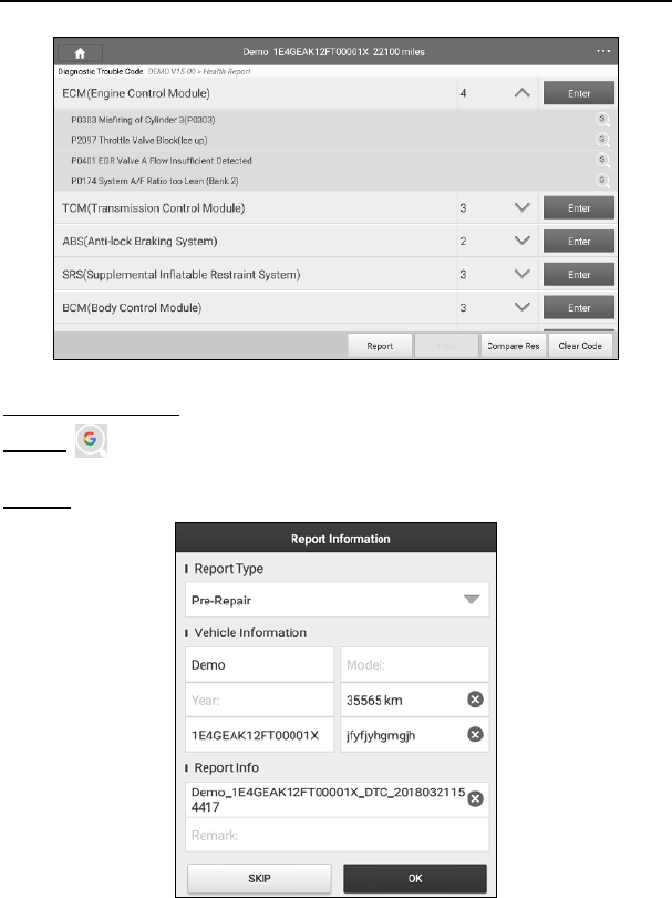
Tap to view all diagnostic trouble codes.
LAUNCH X-431 Throttle User Manual
33
Fig. 5-14
On-screen Buttons:
Search : Highlight a certain DTC item, and then tap it to launch the browser
to search for more detailed information about the selected DTC online.
Report: To save the current data in text format.
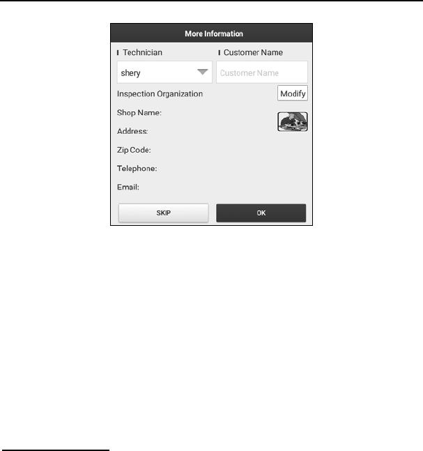
Fig. 5-15
Choose the report type and input the required information, and then tap “OK”.
LAUNCH X-431 Throttle User Manual
34
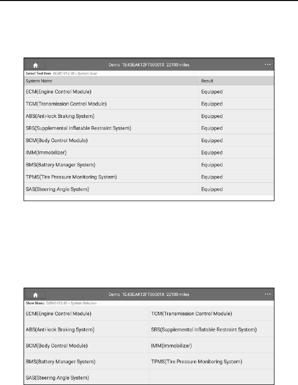
Fig. 5-16
Enter the tester and customer name and then tap “OK” to save it.
For workshop information, tap “Modify” to revise it. Alternatively you can also set
the workshop information in “Settings” -> “Print Information”.
Once you configured the information, it will be automatically generated every
time you saved the diagnostic report. All vehicle and workshop information will
be appended as tags on the diagnostic report, which allows you to easily retrieve
the desired report while performing “Filter” function of Diagnostic Report.
To skip the workshop information, tap “Skip” to go to the next step.
All reports are saved under the “Diagnostic Report” tab in “Reports” on the
“Diagnostic” function module. For details on report operations, please refer to
Chapter 5.4.
Compare Results: Tap to select the pre-repair report to compare. By
comparison of the pre- and post- repair reports, you can easily identify which
DTCs are cleared and which remain unfixed.
*Note: Before performing this function, please make sure that:
• You have saved a pre-repair report of the currently tested vehicle; and
• You have already made some repairs and service and cleared the DTCs after the
pre-repair reported is generated. Otherwise, no differences exist between the pre-
and post- repair reports.
5.2.2 System Scan
This option allows you to quickly scan which systems are installed on the
LAUNCH X-431 Throttle User Manual
35
vehicle.
In Fig. 5-12, tap “System Scan”, the system start scanning the systems. Once
the scanning is complete, the screen will display the result. See Fig. 5-17.
Fig. 5-17
Tap the desired system to advance to the test function selection page. For
detailed operations on test function, please refer to Chapter 5.2.3.
5.2.3 System Selection
This option allows you manually select the test system and function step by step.
In Fig. 5-12, tap “System Selection”, the screen displays as follows:
Fig. 5-18
Swipe the screen from the bottom to view the vehicle system on the next page.
Tap the desired system (take “ECM” for example) to jump to the test function
page.
LAUNCH X-431 Throttle User Manual
36
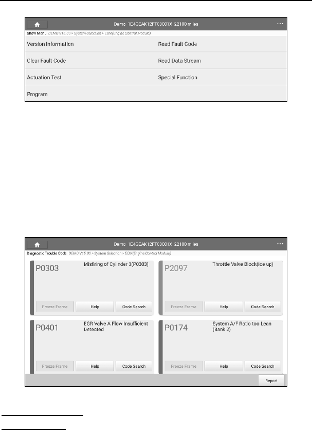
Fig. 5-19
Note: Different vehicle has different diagnostic menus.
A. Version Information
This function is used to read the version information of system mode, vehicle
VIN, software and ECU.
B. Read Fault Code
This function displays the detailed information of DTC records retrieved from the
vehicle’s control system.
In Fig. 5-19, tap “Read Fault Code”, the screen will display the diagnostic result.
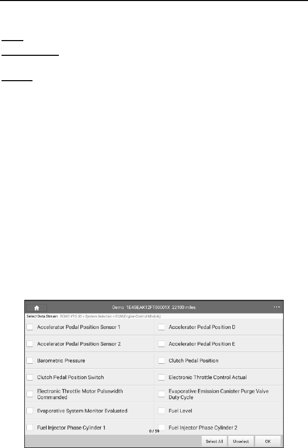
Fig. 5-20
On-screen Buttons:
Freeze Frame: When an emission-related fault occurs, certain vehicle
conditions are recorded by the on-board computer. This information is referred
to as freeze frame data. Freeze frame data includes a snapshot of critical
LAUNCH X-431 Throttle User Manual
37
parameter values at the time the DTC is set.
Help: Tap to view the help information.
Code Search: Tap it to search for more information about the current DTC
online.
Report: To save the current data in text format. All reports are saved under the
tab “Diagnostic Report” in “Report” on the “Diagnostics” function module. For
details on report operations, please refer to Chapter 5.4.
C. Clear Fault Code
After reading the retrieved codes from the vehicle and certain repairs have been
carried out, you can use this function to erase the codes from the vehicle. Before
performing this function, please be sure the vehicle’s ignition key is in the ON
position with the engine off.
In Fig. 5-19, tap “Clear Fault Code”, a confirmation dialog box pops up on the
screen.
Tap “Yes”, the system will automatically delete the currently existing trouble
code.
Note: The trouble code will not disappear until the trouble was completely cleared.
D. Read Data Stream
This option retrieves and displays live data and parameters from the vehicle’s
ECU.
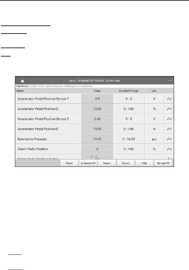
In Fig. 5-19, tap “Read Data Stream”, the system will display data stream items.
LAUNCH X-431 Throttle User Manual
38
Fig. 5-21
On-screen Buttons:
Select All: Tap it to select all items of the current page. To select certain data
stream item, just check the box before the item name.
Unselect: Tap it to deselect all data stream items.
OK: Tap it to confirm and jump to the next step.
After selecting the desired items, tap “OK” to enter the data stream reading
page.
Fig. 5-22
Notes:
1. If the value of the data stream item is out of the range of the standard (reference)
value, the whole line will display in red. If it complies with the reference value, it
displays in blue (normal mode).
2. The indicator 1/X shown on the bottom of the screen stands for the current
page/total page number. Swipe the screen from the right/left to advance/return to the
next/previous page.
There are 3 types of display modes available for data viewing, allowing you to
view various types of parameters in the most suitable way.
9 Value – this is the default mode which displays the parameters in texts and
shows in list format.
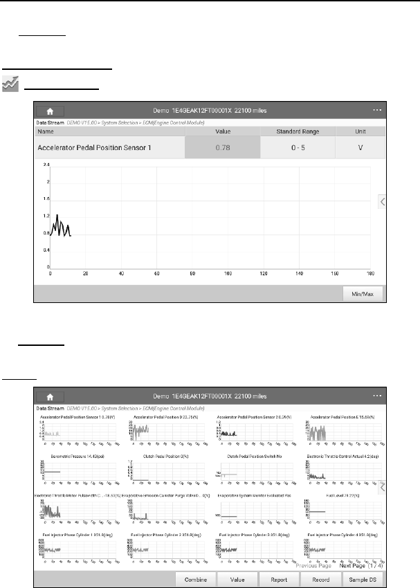
9 Graph – displays the parameters in waveform graphs.
LAUNCH X-431 Throttle User Manual
39
9 Combine – this option is mostly used in graph merge status for data
comparison. In this case, different items are marked in different colors.
On-screen Buttons:
Single graph: Tap it to view the waveform.
Fig. 5-23
• Min/Max: Tap “Min/Max” to define the maximum/minimum value. Once the
value goes beyond the specified value, the system will alarm.
Graph: Tap it to view the waveform.
Fig. 5-24
LAUNCH X-431 Throttle User Manual
40
• Combine: This option is mostly used in graph merge status for data
comparison.
• Value: Tap to display the parameters in texts.
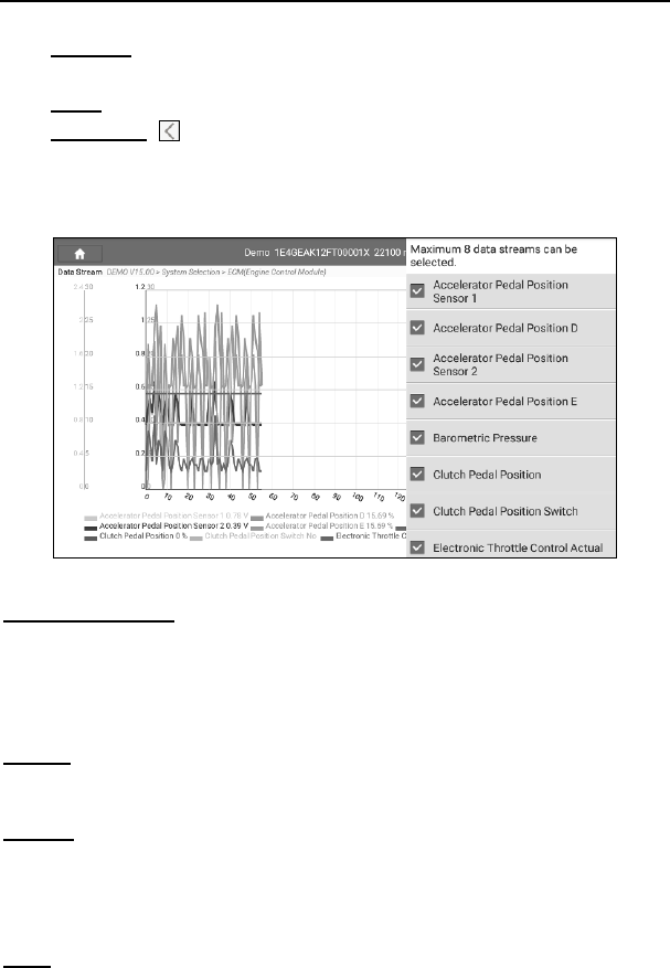
• Customize ( ): Tap it, a pull-down list of the data stream items appears
on the screen. Select (Maximum 8 data stream items can be
selected)/deselect the desired items and then screen will display/remove
the waveforms corresponding to these items immediately.
Fig. 5-25
Select Sample DS: Tap it to select the sample DS file, the values you
customized and saved in process of DS sampling will be imported into the
“Standard Range” column for your comparison.
*Before executing this function, you have to sample the values of data stream items and
save it as a sample DS file.
Report: To save the current data in text format. All reports are saved under the tab
“Diagnostic Report” in “Report” on the “Diagnostics” function module. For details on
report operations, please refer to Chapter 5.4.
Record: Tap to start recording diagnostic data for future playback and analysis.
The saved file follows the naming rule: It begins with vehicle type, and then the
record starting time and ends with .x431 (To differentiate between files, please
configure the accurate system time). The file is stored in “Report” on the
“Diagnostics” function module.
Help: Tap to view the help information.
LAUNCH X-431 Throttle User Manual
41
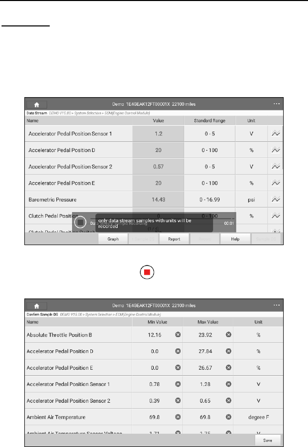
Sample DS: This item enables you to customize the standard range of live data
stream items and save it as DS sample file. Each time you run the data stream
items, you can call out the corresponding sample data to overwrite the current
standard range.
Tap it to start recording the sample data (* Only data stream items with units will be
recorded), and the screen displays as below:
Fig. 5-26
Once recording is complete, tap to stop it and navigate to the data
modification screen.
LAUNCH X-431 Throttle User Manual
42
Fig. 5-27
Tap the Min./Max. value to change it. After modifying all desired items, tap
“Save” to save it as a sample DS file. All DS files are stored under the “Data
Stream Sample” file in “User Info”.
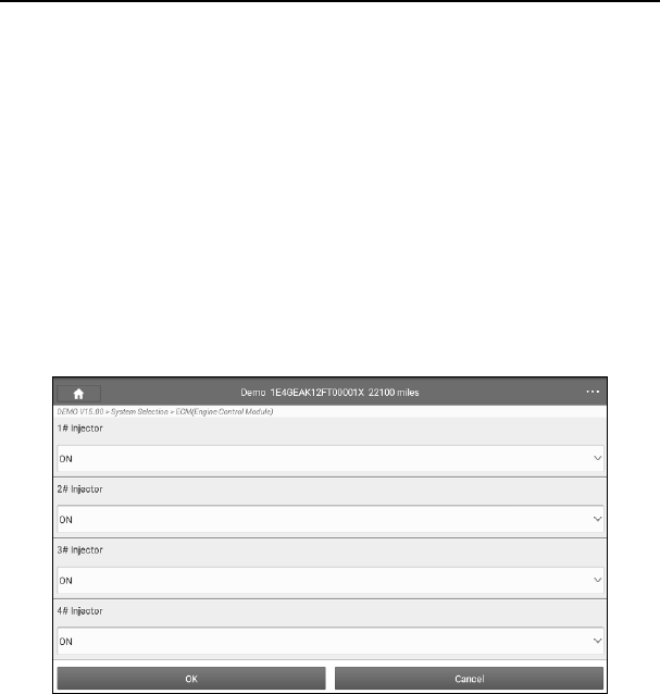
E. Actuation Test
This option is used to access vehicle-specific subsystem and component tests.
Available test vary by vehicle manufacturer, year, and model.
During the actuation test, the X-431 Torque handset outputs commands to the
ECU in order to drive the actuators, and then determines the integrity of the
system or parts by reading the ECU data, or by monitoring the operation of the
actuators, such as switching a injector between two operating states.
In Fig. 5-19, tap “Actuation Test”, the system will display as follows:
Fig. 5-28
Simply follow the on-screen instructions and make appropriate selections to
complete the test. Each time when an operation is successfully executed,
“Completed” displays.
5.3 Tech to Tech (Remote Diagnosis)
This option aims to help repair shops or technicians launch instant messaging
and remote diagnosis, making the repair job getting fixed faster.
Tap “Tech to Tech” on the Diagnostics function module, the screen appears
LAUNCH X-431 Throttle User Manual
43
blank by default.
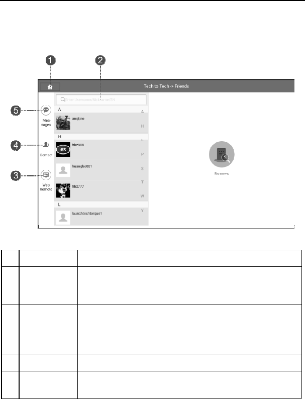
5.3.1 Interface layout
Fig. 5-29
1 Home button Tap to navigate to the Job menu.
2 Search bar
Directly input the username of the X-431 Throttle to start
searching, and then tap the desired one to add it into your
friend list.
3 WEB Remote
switch
Tap to slide the switch to ON, the X-431 Throttle keeps
online and becomes visible on the web client. In this case,
inform the technician of your product S/N, and he/she will
control your X-431 Throttle remotely.
4 Contact tab Tap to enter the friend list. By default it appears blank.
5 Message tab Once an incoming message reaches, a red dot will appear
on the upper right corner of the tab.
5.3.2 Add Friends
Tap “Contact” to enter the contact page. By default it appears blank.
In the search bar, input the partner’s username and tap “Search” button next to
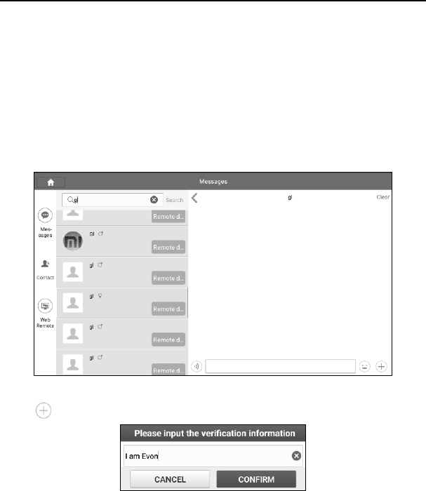
LAUNCH X-431 Throttle User Manual
44
the search bar to starts searching from golo business database.
The partner must be the users who have registered their Launch’s diagnostic tools. They
may be the following:
• Workshop
• Technician
• golo users
Once the result matches the keyword, tap the desired one from the search result
to enter the instant messaging mode.
Fig. 5-30
Tap “ ” and select “Add Friend” from the option menu, a dialog box pops up.
Fig. 5-31
Tap “CONFIRM” to send your request.
Once the partner receives the request, a beep will sound. Tap the “Message”
tab:
• Once the partner agreed your request, he/she will automatically be listed in
the Contact tab.
• If a technician sent you a friend request, you can tap “Agree” to confirm and
LAUNCH X-431 Throttle User Manual
45
his/her name will appear in the friend list (Contact). Or tap “Ignore” to ignore
this request.
5.3.3 Start instant messaging
Note: The I/M (Instant Messaging) function is open to all users who had Launch’s
diagnostic tool equipped with this module.
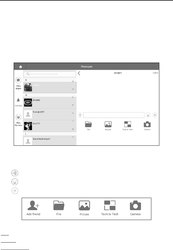
After adding your friends, tap the desired one’s photo to enter a screen similar to
the following:
Fig. 5-32
Tap the input field and use the on-screen keyboard to enter the text message,
and then tap “Send” to send it.
Tap to send the voice message.
Tap to send the emoj.
Tap to call out more function options.
Fig. 5-33
File: Choose diagnostic reports or local files to send.
Picture: Choose screenshots or pictures to send.
Tech to Tech: To start a remote diagnostic session. For details, refer to Chapter
LAUNCH X-431 Throttle User Manual
46
5.3.4.
Camera: Open camera to take pictures.
5.3.4 Launch remote diagnosis (Device-To-Device)
The X-431 Throttle handset is allowed to launch remote diagnosis with other
diagnostic tools (including but not limited to the X-431 Throttle) of Launch family,
which are equipped with this module.
* Note: Before performing this operation, please make sure the following no matter
which side sends the remote request:
y Turn on the vehicle power supply.
y Throttle should be in a closed position.
y The X-431 Throttle should be properly connected to the vehicle’s DLC and a
successful communication is required.
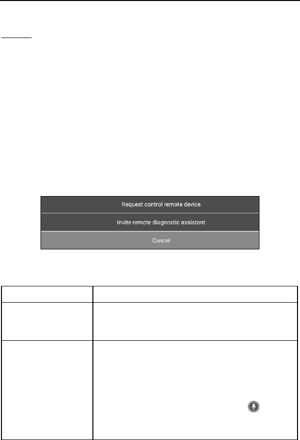
In Fig. 5-33, tap “Tech to Tech”, a pull-down menu including the following options
appears:
Fig. 5-34
These options are defined as follows:
Actions Results
Send remote
diagnostic reservation
Tap it and input the reservation title or scheduled date
of the remote diagnosis, and then tap “Confirm” to
send.
Request control
remote device
Request to control the partner’s device remotely to
help him diagnose the vehicle.
*Notes:
y Remote diagnosis has the same diagnostic steps as
manual diagnosis.
y In process of remote diagnosis, tap the button to
send a voice message.
y Once vehicle diagnosis is complete, a report will be
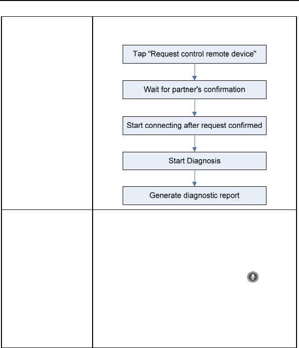
LAUNCH X-431 Throttle User Manual
47
created. Input your comments on this report, and then
tap “Send Report” to send it to the partner.
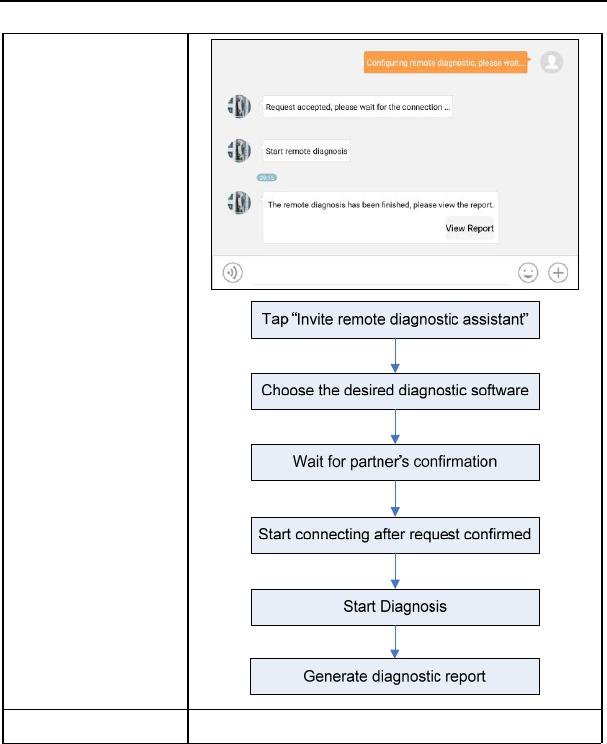
Invite remote
diagnostic assistant
If you need support, just use this option to invite a
technician to perform a remote control on your tool.
*Notes:
y Remote diagnosis has the same diagnostic steps as
manual diagnosis.
y In process of remote diagnosis, tap the button to
send voice message.
y Once you received the report from the partner, tap
“View Report” to view details. All diagnostic reports
are saved under the “Remote Diagnostic Reports” tab
of “My Reports” in “User Info”.
LAUNCH X-431 Throttle User Manual
48
Cancel To cancel this operation.
LAUNCH X-431 Throttle User Manual
49
5.3.5 Launch remote diagnosis (Device-To-PC)
Except that the remote diagnosis can be done between different Launch’s
diagnostic tools that come loaded with the module, user also can ask for remote
control from PC client technician.
Fig. 5-35
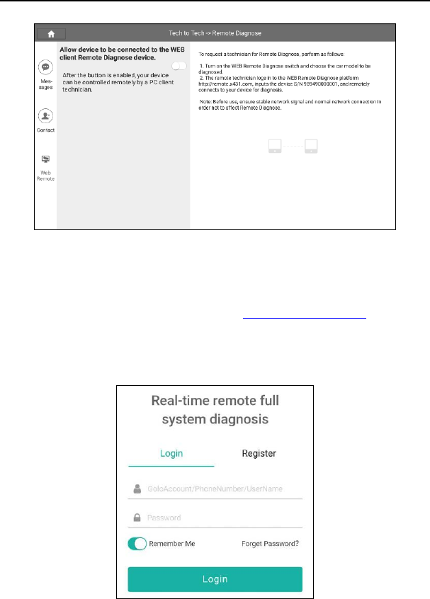
Tap the “Web Remote” tab, the screen displays as follows:
LAUNCH X-431 Throttle User Manual
50
Fig. 5-36
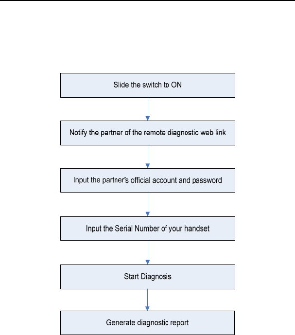
1. Slide the switch “Allow device to be connected to the WEB client remote
diagnostic device” to ON so that the partner can find and access to this
device while using the PC.
2. Notify the partner of the PC client website http://remote.x431.com. When the
partner opens the link, the PC displays as below:
*Note: Before processing remote diagnosis, please make sure the X-431 Throttle
handset is properly connected to the vehicle.
Fig. 5-37
LAUNCH X-431 Throttle User Manual
51
3. Tell the partner to input his own official technician account and password, and
then tap “Login” to navigate to the following figure.
Fig. 5-38
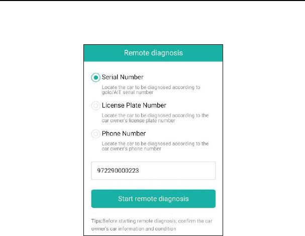
4. Tell the partner to check the box “Serial number” and enter the Serial Number
provided by you, and then tap “Start remote diagnosis”.
5. A popup displays to ask for your confirmation to allow remote control on your
device.
6. Tap “Allow” to accept, or tap “Deny” to reject.
In process of remote diagnosis, please note the following things:
1) You are not suggested to execute any actions.
2) The partner is not allowed to save any diagnostic reports or records on
your handset.
The operations in remote diagnosis are same as those in local diagnosis. Once
the session is complete, a remote diagnostic report will be automatically
generated.
LAUNCH X-431 Throttle User Manual
52
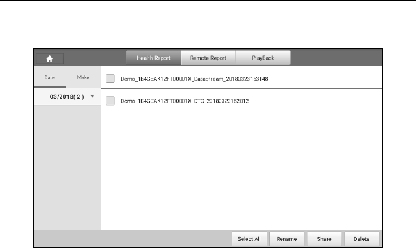
5.4 Manage Reports
Fig. 5-39
5.4.1 Health Report
This module stores all diagnostic reports generated in process of vehicle
diagnosis.
All the diagnostic reports are sorted by Date and Make. Tap the desired type to
re-arrange and filter it.
• To select certain report, check the box before the report. To select all reports,
tap “Select All”. To deselect all, tap “Unselect”.
• To revise the filename of the report, select the desired one and tap
“Rename”.
• To share the report with others, select the desired one and then tap “Share”.
• Select the desired report and then tap “Delete” to delete it.
5.4.2 Remote Report
This option lists all diagnostic reports generated in process of remote
diagnostics.
5.4.3 Playback
If user records the running parameters or waveform graphs while reading data
stream, it will be saved as diagnostic records and appear under this tab.
Tap “Playback”, and select certain diagnostic record to enter.

LAUNCH X-431 Throttle User Manual
53
Select the desired data stream items and tap “OK” to jump to the playback page.
On-screen Buttons:
Graph – displays the parameters in waveform graphs.
Combine – this option is mostly used in graph merge status for data comparison.
In this case, different items are marked in different colors.
Value – this is the default mode which displays the parameters in texts and
shows in list format.
Frame Playback – plays back the recorded data stream items frame by frame.
Once it is in frame playback mode, this button changes into “Auto Playback”.
5.5 I/M Readiness
An important part of a vehicle’s OBD II system is the Readiness Monitors, which
are indicators used to find out if all of the emissions components have been
evaluated by the OBD II system. They are running periodic tests on specific
systems and components to ensure that they are performing within allowable
limits.
Currently, there are eleven OBD II Readiness Monitors (or I/M Monitors) defined
by the U.S. Environmental Protection Agency (EPA). Not all monitors are
supported in every vehicles and the exact number of monitors in any vehicle
depends on the motor vehicle manufacturer’s emissions control strategy.
Continuous Monitors -- Some of the vehicle components or systems are
continuously tested by the vehicle’s OBD II system, while others are tested only
under specific vehicle operating conditions. The continuously monitored
components listed below are always ready:
1)Misfire
2)Fuel System
3)Comprehensive Components (CCM)
Once the vehicle is running, the OBD II system is continuously checking the
above components, monitoring key engine sensors, watching for engine misfire,
and monitoring fuel demands.
Non-Continuous Monitors -- Unlike the continuous monitors, many emissions
and engine system components require the vehicle to be operated under
specific conditions before the monitor is ready. These monitors are termed
non-continuous monitors and are listed below:
1) EGR System
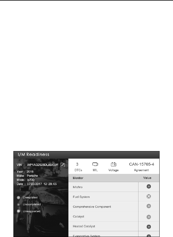
LAUNCH X-431 Throttle User Manual
54
2) O2 Sensors
3) Catalyst
4) Evaporative System
5) O2 Sensor Heater
6) Secondary air Injection
7) Heated Catalyst
8) A/C system
I/M refers to Inspection and Maintenance that is legislated by the Government to
meet federal clean-air standards. I/M Readiness indicates whether or not the
various emissions-related systems on the vehicle are operating properly and are
ready for Inspection and Maintenance testing.
The purpose of the I/M Readiness Monitor Status is to indicate which of the
vehicle’s Monitors have run and completed their diagnosis and testing, and
which ones have not yet run and completed testing and diagnosis of their
designated sections of the vehicle’s emissions system.
The I/M Readiness Monitor Status function also can be used (after repair of a
fault has been performed) to confirm that the repair has been performed
correctly, and/or to check for Monitor Run Status.
Tap [I/M Readiness] on the Job Menu to start checking. After checking all I/M
readiness status, the screen will output the result:
Figure 5-40
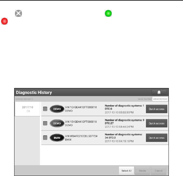
LAUNCH X-431 Throttle User Manual
55
Note: means not available on this vehicle, means incomplete or not ready,
means Completed or Monitor Ok.
5.6 How to View Diagnostic History?
Generally once a vehicle diagnosis is performed, X-431 Throttle will record the
every details of diagnostic process. The History function provides direct access
to the previously tested vehicles and users can resume from the last operation,
without the necessity of starting from scratch.
Tap “History” on the Diagnose main menu screen, all diagnostic records will be
listed on the screen in date sequence.
Fig. 5-41
• Tap certain vehicle model to view the details of the last diagnostic report.
• To delete certain diagnostic history, select it and then tap “Delete”. To
delete all historical records, tap “Select All” and then tap “Delete”.
• Tap “Quick access” to directly navigate to the function selection page of
last diagnostic operation. Choose the desired option to proceed.
5.7 Diagnostic Feedback
This item allows you to feedback your diagnostic problems to us for analysis and
troubleshooting.
Tap “Diag. Feedback”, the following 3 options will be displayed on the left
column of the screen.
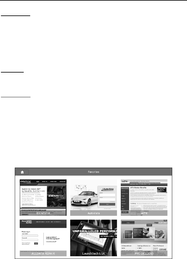
LAUNCH X-431 Throttle User Manual
56
A. Feedback
Tap a tested vehicle model to enter the feedback screen.
1) Tap “Choose File” to open the target folder and choose the desired diagnostic
logs.
2) Choose the failure type and fill in the detailed failure description in the blank
text box and telephone or email address. After inputting, tap “Submit Result”
to send it to us.
B. History
Tap it to view all diagnostic feedback records. Different process states are
marked with different colors.
C. Offline list
Tap it to display all diagnostic feedback logs which have not been submitted
successfully due to network failure. Once the handset gets a stable network
signal, it will be uploaded to the remote server automatically.
5.8 View Repair Information
This feature provides a quick dial to some authoritative official automotive repair
websites for your reference and retrieval. Meanwhile, it also allows you to add
some frequently used websites into Favorites so that you can quickly access
them in future.
Fig. 5-42
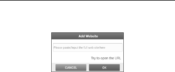
LAUNCH X-431 Throttle User Manual
57
Tap the desired website to visit it.
To add certain website into favorites, scroll the screen to until it reaches to the
bottom, tap “+”, a dialog box similar to the following appears.
Fig. 5-43
Type in the full web site in the blank, and tap “OK”, it will be listed in the
Favorites.
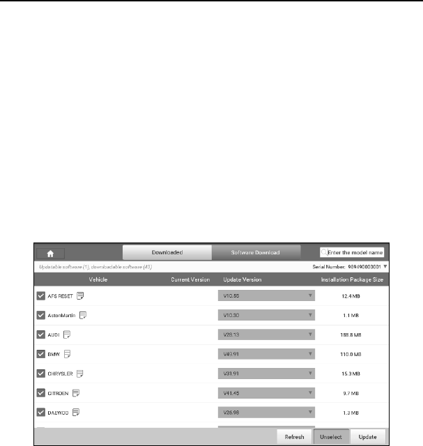
LAUNCH X-431 Throttle User Manual
58
6 Software Update
This module allows you to update the diagnostic software & App, and renew the
software subscription.
6.1 Update Diagnostic Software & APP
If you did not download the software in process of product registration or a
pop-up message prompting you that some new software can be updated, you
may use this option to download it or keep it synchronized with the latest
version.
Tap “Software Upgrade” to enter the update center.
Fig. 6-1
By default, the system enters the “Downloaded” page and all diagnostic software
to be updated is selected.
* Note: If some software has not been downloaded yet, tap “Software Download” to
download it.
• To deselect certain software, tap “Unselect”, and then check the box next to
vehicle model.
• To refresh the downloaded list, tap “Refresh”.
• Tap “Update” to start downloading. It may take several minutes to finish it,

LAUNCH X-431 Throttle User Manual
59
please be patient to wait.
• To pause downloading, tap “Stop”. To resume it, tap “Continue”. If network
connection failure occurs, tap “Retry” to try again.
Once download is finished, the software packages will be installed automatically.
6.2 Renew software subscription
If the software subscription is due or expires, the system will prompt you to
renew your subscription and a “Renewal” button will appear on the bottom of the
update page.
There are 2 ways available for you to make payment: PayPal and Subscription
Renewal Card (*need to buy it from the local dealer where you purchased the X-431
Throttle).
A. Using PayPal
1. Tap “Renewal” on the update page to navigate to the renewal type selection
screen.
2. Select “PayPal”, and then follow the on-screen instructions to finish the
transaction.
3. After payment, go to update center to update the diagnostic software.
B. Using Subscription Renewal Card
1. Tap “Renewal” to navigate to the renewal type selection screen.
2. Select “Subscription Renewal Card”.
3. Input the 24-digit pin code of Subscription Renewal Card and then tap
“Submit” to finish the renewal.
4. Go to update center to update the diagnostic software.
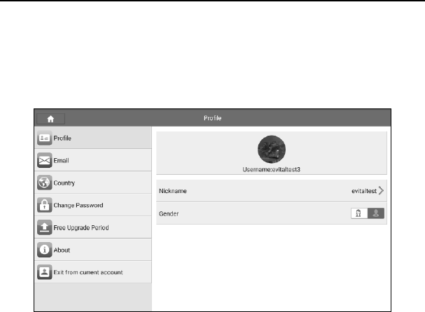
LAUNCH X-431 Throttle User Manual
60
7 Profile
Use this option to configure/revise personal information.
Fig. 7-1
7.1 Profile
This option is used to create your personal profile.
7.2 Email
This option allows you modify your Email address.
7.3 Change Password
This option allows you change your login password.
7.4 Free Upgrade Period
This option lets you check the free update period of the diagnostic software.
7.5 About
Use this item to check the version of the App and disclaimer page.

LAUNCH X-431 Throttle User Manual
61
7.6 Exit from current account
To logout the current user ID, tap “Exit from current account”.
To login the system again, tap “Login”.

LAUNCH X-431 Throttle User Manual
62
8 Settings
This function allows users to manage personal information and VCI connector.
8.1 General
It enables you to make some application settings and view software version
information etc.
8.1.1 Units of Measurement
It is designed to set the measurement unit. Metric System and English System
are available.
81.2 Expiration Reminder
All pre-installed diagnostic software is free to use for 30 days. Once it expires, it
will be locked automatically and the system will prompt you to activate your
dongle if the expiration reminder is ON.
8.1.3 Identifix Settings
This option is used to set whether the free 30-day trial Identifix shows or not.
8.1.4 Auto Update
This option is used to set whether automatic update function is ON.
8.2 VCI
This option allows you to manage all activated VCI devices.
If several VCI devices are activated on this tool, a list of VCI devices will be
displayed on the screen. If your tool extends to support heavy-duty trucks, you
need to switch to the corresponding VCI module before diagnosing it.
Once you choose the device that belongs to other account, you have to log out,
and then input the right account to continue.
8.3 VCI Management
If you use the current account to test a vehicle with another X-431 Throttle,
please use this item to unpair the VCI device with the previously paired X-431
Throttle.
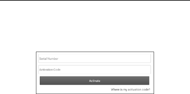
LAUNCH X-431 Throttle User Manual
63
*Note:pleasebesuretokeeptheVCIdevicepoweredonwhileperformingthe
operation.
8.4 Activate VCI
This item lets you to activate a new VCI device.
Fig. 8-1
Input the Serial Number and Activation Code (can be found from the included
Password Envelope), and then tap “Activate” to activate it.
8.5 Firmware Fix
Use this item to upgrade and fix diagnostic firmware. During fixing, please do not
cut power or switch to other interfaces.
8.6 Icon Size
This feature allows you to set the size of the diagnostic software icon according
to your preference.
Drag the slider to different size and the system will display the corresponding
effect.
8.7 Color Theme
This item enables you to set the color theme of the App.
Once you changed it, you have to reboot the system for the change to take
effect.
8.8 Printer Set
This option is used to establish a wireless connection between X-431 Throttle
and the printer (sold separately) while performing printing operations.

LAUNCH X-431 Throttle User Manual
64
The App is compatible with the “Wi-Fi Printer” (sold separately) and “System”
(external printer).
Follow the steps below to connect the Wi-Fi printer.
1. Tap “Printer Set”.
Below describes how to configure the Wi-Fi Printer.
A. If it is the first time you have operated this printer, please proceed the
following:
2. For initial use, you are suggested to reset the printer: Press and hold [MODE]
& [FEED] for 8 seconds, the following resetting command will be printed out:
at + default = 1
ok
at + reboot = 1
rebooting...
3. Tap “Reset” to configure Wi-Fi printer.
Step 1: Connect the printer:
Tap “Scan” to select the desired printer hotspot named with
X-431PRINTER-XXXX (XXXX stands for 4 characters), and then tap
“Connect” to enter Step 2.
Step 2: Join the printer into LAN:
Tap “Scan” to select the desired local Wi-Fi network from the list, and type in
the security password (If it is an open network, password is not required), and
then tap “Confirm”.
4. Once the Wi-Fi network of the printer is connected and the printer is found,
tap “Test Print” to test the printing.
Now you can use the Wi-Fi printer to print!
If the printer is not found, please reset the printer to default factory settings
(refer to Step 2 for details) and check whether the current device and the
printer are on the same LAN.
B. If you have configured the Wi-Fi printer to the LAN:
2. Tap “Connect to Printer”:
a). If the local network remains as it is, tap “Test Print” directly to test the
printing.
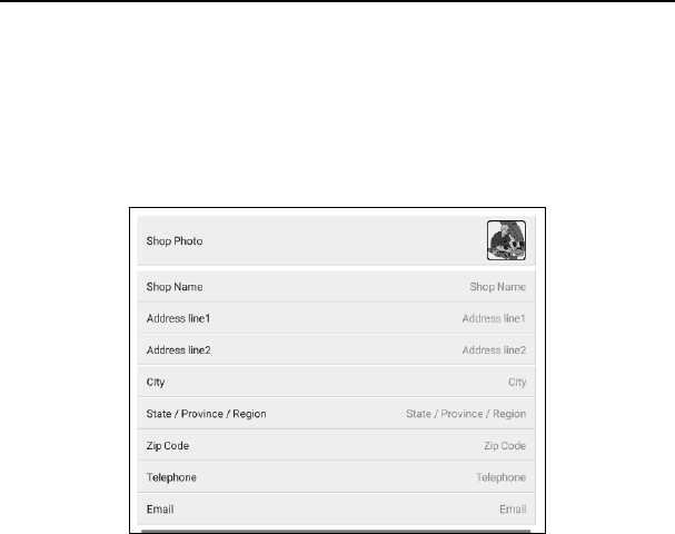
LAUNCH X-431 Throttle User Manual
65
b). If the local network changes, you have to reboot and reconfigure the Wi-Fi
printer.
8.9 Print Information
This option lets you define your print information. It mainly includes Workshop,
Address, Zip Code, Telephone, Email etc.
Fig. 8-2
After inputting, tap “Save”.
Once you saved the print information, it will be entered automatically in the
“More Information” box every time you save the diagnostic report.
8.10 Data Stream Sample
This feature allows you to manage the recorded data stream sample files.
8.11 Vehicle Voltage
This item is used to detect the voltage of the currently tested vehicle when the
VCI is plugged into the vehicle’s DLC.
8.12 Diagnostic Software Clear
This item allows you to hide/clear the diagnostic software that is not frequently
used.

LAUNCH X-431 Throttle User Manual
66
Tap “Diagnostic Software Clear” to enter.
Under the “Hide Software” tab, select the desired diagnostic software and tap
“Hide”, it will become invisible. Tap “Unhide” to undo the hide operation.
Under the “Remove Software” tab, select the desired diagnostic software and
tap “Delete”, it will disappear from the screen.
8.13 Backup/Restore
This option lets you backup/restore the important data to/from external USB
device.
A. Backup
1). Insert the U disk into the Data Transmission Port of the handset.
2). Tap “Backup” to select the data folder to be backed up.
3). Tap “Backup” on the bottom of the screen to copy it to the U disk.
4). Unplug the U disk from the handset.
B. Restore
1). Insert the U disk into the Data Transmission Port of the handset.
2). Tap “Restore” to select the data folder to be restored.
3). Tap “Restore” on the bottom of the screen to copy it to the handset.
4). Unplug the U disk from the handset.
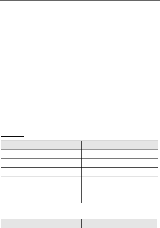
LAUNCH X-431 Throttle User Manual
67
9 Sensorbox (Toolbox)
9.1 Product Summary
X-431 Throttle provides an optional function of automotive sensor simulation test.
“Sensor” function is specially designed to diagnose and simulate vehicle sensor
faults quickly and conveniently, including “DC voltage simulation”, “Fixed
frequency simulation”, “Predefined waveform simulation” and “Hand-painted
waveform simulation”.
Vehicle sensors are the signal input devices for electrical control systems, which
can transform all kinds of running parameters, such as vehicle speed, coolant
temperature, engine RPM, air flow, throttle opening, etc., into the electronic
signal for the vehicle computer who can optimize the engine running status per
the above-mentioned parameters to keep the engine working in a prime status.
Meanwhile, it integrates the functions of automobile multimeter (For detailed
operations on multimeter, please refer to Chapter 10), which enables users to
perform voltage, resistance and frequency test. (The function utilizes the same
hardware device as the sensor module)
It features automotive sensor simulation test and multimeter test function.
Sensorbox
Parameters Scope
Precision ±5%
Voltage range -5V~+5V
Max output current 70mA
Predefined frequency range 0~150Hz
Square-wave signal pulse frequency 0~15KHz
Square-wave signal duty ratio 10%~90%
Multimeter
Parameters Scope
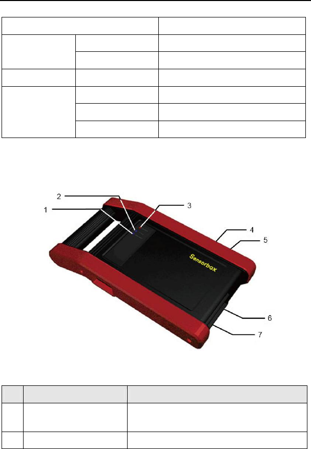
LAUNCH X-431 Throttle User Manual
68
Precision ±5%
Voltage test Testing range DC-400V~+400V
Input impedance 10Mohm
Resistance test Testing range 0~40Mohm
Frequency test Testing range 0~25KHz
Input impedance 1000Gohm
Input voltage 1~12V
9.2 Structure & Accessories
9.2.1 Sensorbox structure
Fig. 9-1 Structural diagram of Sensorbox
Table 9-1 shows the ports and indicators for X-431 Throttle sensorbox
No. Name Description
1 Data receiving indicator Indicator (green) for receiving data from main
unit.
2 Data sending indicator Indicator (green) for sending data to main
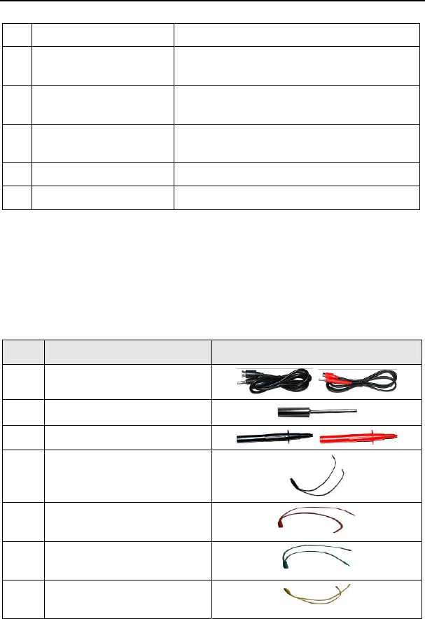
LAUNCH X-431 Throttle User Manual
69
unit.
3 Power indicator It keeps steady on (red) after the sensorbox
is powered on.
4 Type-B USB port Connect to main unit with USB cable when it
is applied as separated USB device.
5 Power connector Connect to power supply through the power
adaptor.
6 COM Common terminal of multimeter
7 VΩHz Testing terminal of multimeter
9.2.2 Sensorbox accessories
The sensorbox accessories include sensor test cable, probe etc. See Table 9-2.
As the product configuration can be different, the accessories included with the
product may differ from the accessories listed on this manual. Please see the
packing list attached to the product for the detailed accessories.
Table 9-2 Accessory checklist
No. Name Picture
1 Sensor test cable
2 Sensor probe
3 Multimeter probe
4 Electronic control converting
cable 1
5 Electronic control converting
cable 2
6 Electronic control converting
cable 3
7 Electronic control converting
cable 4

LAUNCH X-431 Throttle User Manual
70
9.3 Sensor Simulation
9.3.1 Connections
1. Firstly, power the X-431 Throttle tablet on.
2. Plug one end of the sensor test cable (black) into the “COM” interface of the
sensorbox, and then the other end to the test probe or electronic control
converting cable.
3. Connect one end of the sensor test cable (red) into the “VΩHz” interface of
the sensorbox, and then the other end to the test probe or electronic control
converting cable.
Note: Choose corresponding cables and test probes according to different terminals.
9.3.2 Simulation test
Simulation test enables users to exactly judge if the sensor is good or not to
avoid replacing components blindly. For example, the trouble code indicates the
fault is in water temperature sensor itself. But we need to confirm whether the
fault results from water temperature sensor or the connections between ECU
and sensors, or ECU itself. In this case, we can make full use of simulation test
to input the signal of simulating water temperature sensor, instead of water
temperature sensor, to the microcomputer. If the engine works better and the
fault vanishes, the fault is in the water temperature sensor. If the fault still occurs,
input the signal to the corresponding terminals of ECU. Consequently, if the fault
disappears, the fault lies in the connection between water temperature sensor
and ECU, otherwise, the fault exists in ECU.
After all connections are properly made (refer to Chapter 9.3.1 for details),
launch X-431 Throttle application and enter the Job menu interface, then tap
“Toolbox” -> “Sensor” to enter the test selection screen. See Fig. 9-2.
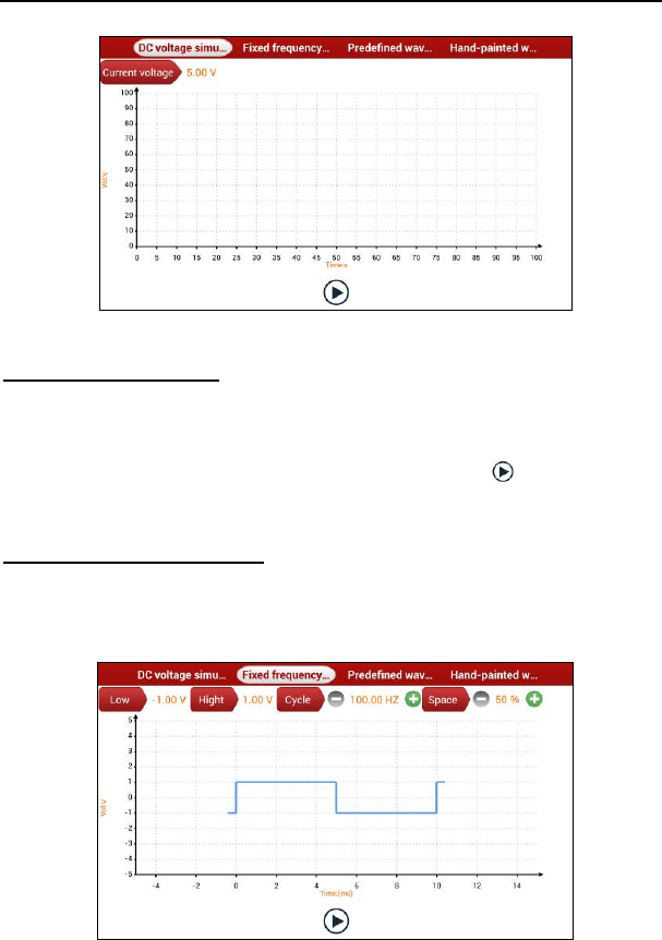
LAUNCH X-431 Throttle User Manual
71
Fig. 9-2
1. DC voltage simulation
In Fig. 9-2, tap [Current voltage], then tap “+” or “-” to adjust the output voltage
value. Alternatively, user can also tap edit box, then use the on-screen keyboard
to input the desired value directly. After selecting or inputting the desired voltage
based on the working characteristics of sensor, tap the button, then the
X-431 Throttle will begin to output the simulation voltages. Please note the red
probe is the output terminal of simulation voltage.
2. Fixed frequency simulation
This option enables you to simulate the square wave signal of pulse frequency
of 0.1 ~ 15 kHz, amplitude range of -5V ~ +5V and duty cycle 10% ~ 90%.
In Fig. 9-2, tap “Fixed frequency simulation” to enter a screen similar to Fig. 9-3.
Fig. 9-3
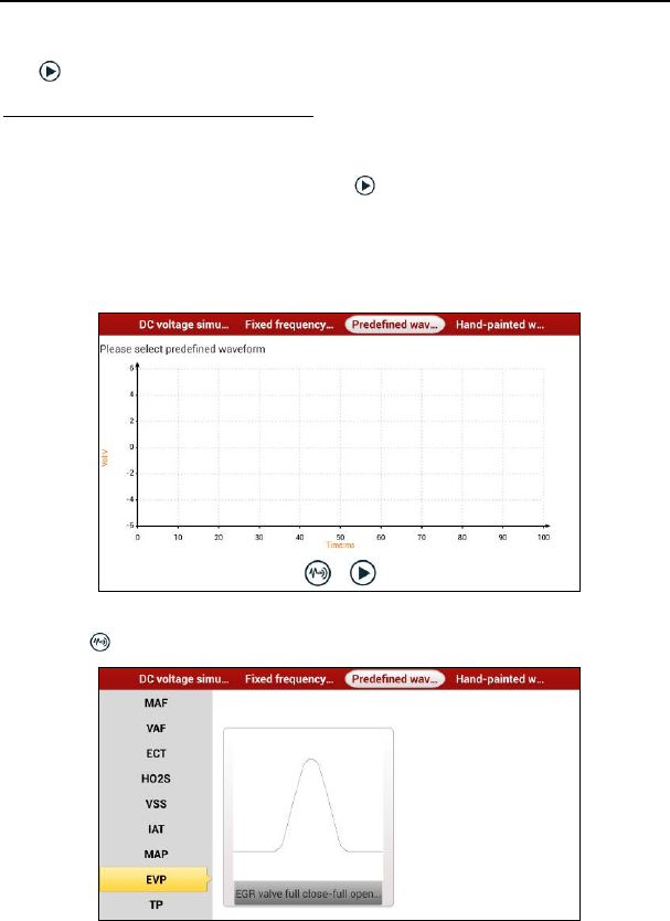
LAUNCH X-431 Throttle User Manual
72
Tap the setting option tab, then tap “+” or “-” to adjust the output. After setting,
tap to perform the test.
3. Predefined waveform simulation
X-431 Throttle provides some common sensor waveforms which have been
predefined to facilitate users to simulate sensor signals. As long as you call out
the predefined waveform, then tap to start simulating output of
corresponding sensor waveform and no more parameter settings of simulation
waveform are required.
In Fig. 9-3, tap “Predefined waveform simulation” to enter the screen shown as
Fig. 9-4.
Fig. 9-4
Here, tap button, a screen similar to Fig. 9-5 will appear.
Fig. 9-5
In Fig. 9-5, the left setting column stands for sensor types and the right area
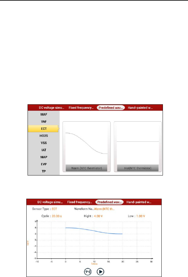
LAUNCH X-431 Throttle User Manual
73
displays waveform. The sensor types are explained as below:
ECT: Coolant Temperature Sensor
EVP: EGR Valve Position Sensor
HO2S: Heated Oxygen Sensor
IAT: Intake Air Temperature Sensor
MAF: Mass Air Flow Sensor
MAP: Manifold Absolute Pressure Sensor
TP: Throttle Position Sensor
VAF: Volume Air Flow Sensor
VSS: Vehicle Speed Sensor
For example, tap “ECT” – “Warm (NTC Thermistor)” in Fig. 9-5, the right screen
will display the waveform of the sensor.
Fig. 9-6
In Fig. 9-6, tap the waveform, then the pre-defined waveform has been set.
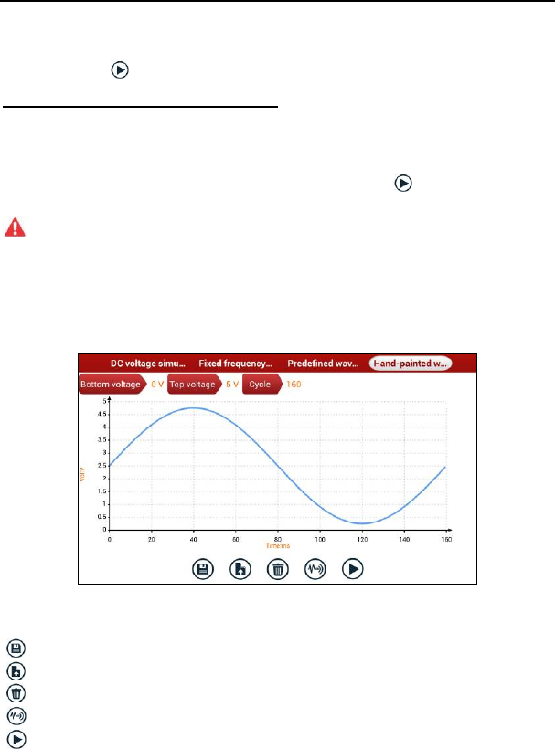
LAUNCH X-431 Throttle User Manual
74
Fig. 9-7
In Fig. 9-7, tap button to perform simulation test.
4. Hand-painted waveform simulation
This option offers great convenience for users to simulate special waveform or
fault wave. Users only draw the shape of waveform which needs to be simulated
in central drawing area, and then configure some parameters on the top, namely
high level, low level, and cycle of waveform, then tap , X-431 Throttle will
output a waveform as desired.
Warning: Just draw a complete periodic waveform (when it is output, the system
will regard the waveform in the drawing area as a periodic one). Users should draw as
large as wave in drawing zone so that the system can sample more points to reduce
tolerance.
In Fig. 9-2, tap “Hand-painted waveform simulation”, a screen similar to Fig. 9-8
will appear.
Fig. 9-8
Button descriptions:
[]: Save the current waveform.
[]: Loads the previously saved hand-drawn waveform.
[]: Clear all hand-drawn waveform.
[]: Click to call out the predefined waveform for reference.
[]: Continues the following operation.
9.3.3 Precautions on checking vehicle sensor
y Hold the connector when plugging or unplugging it. Do not pull the cable for

LAUNCH X-431 Throttle User Manual
75
unplugging.
y At first check the fuse, fusible line and terminals. Then check others after
eliminating these faults.
y When measuring voltage, the ignition switch should be on and the battery
voltage should not be less than 11V.
y When measuring voltage, please shake the lead lightly in the vertical and
horizontal direction for more precision.
y When checking whether there is open in the line, disconnect the CEU and the
relevant sensor at first, then measure the resistance among the ports of
sensor in order to determine whether open-circuit / contact fault exists or not.
y When checking if there is a short in the line, please disconnect the CEU and
the relevant sensor, then measure the resistance value of the ports between
the connected port and the vehicle body. If the resistance value is more than
1MΩ, no fault occurs.
y Before disassembling the engine electrical control system cable, cut off the
power supply, that is, turn the ignition switch OFF and disconnect the cables
on the battery poles.
y Contact the test probe and the two terminals/ the two leads to be measured
when measuring the voltage between the two terminals or the two leads.
y Contact the red test probe to the terminal/ the cable to be measured, and the
black probe to the ground when measuring voltage of one terminal/ one
cable.
y When checking the continuity of the terminals, contacts and leads, the
method for measuring their resistances can be used.
y Check the faults in the terminals of the CEU to sensors, relays, etc.
y There are two test probes in the testing wire. The black one is the common
signal terminal (signal GND); the red one is the input terminal for voltage,
resistance, and frequency test and output terminal for simulation voltage,
simulation frequency and oxygen sensor. Please choose the correct probes
to match the different terminals.
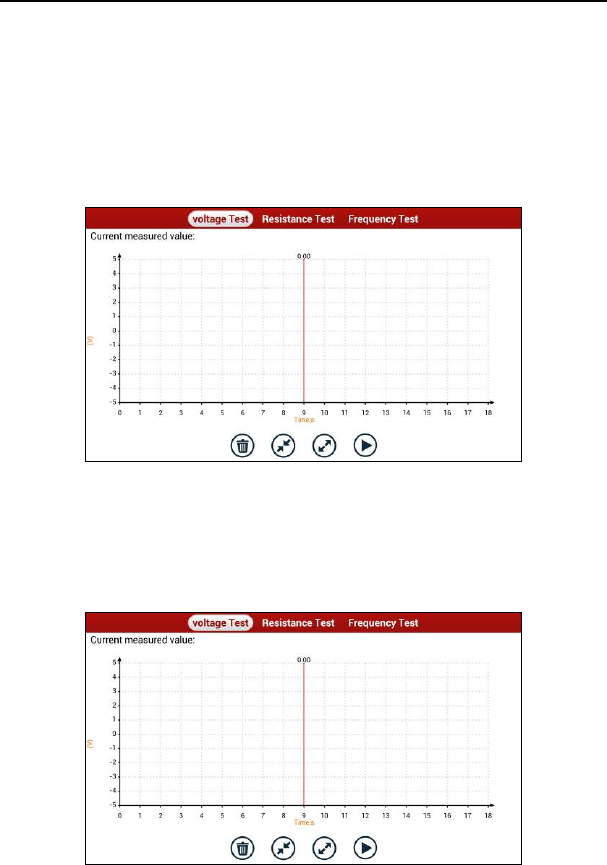
LAUNCH X-431 Throttle User Manual
76
10 Multimeter (Toolbox)
10.1 Main Menu
Make sure the X-431 Throttle handset and the sensorbox are properly
connected (Refer to Chapter 9.3.1 Connections for details), launch X-431
Throttle application, tap “Toolbox” -> “Multimeter” to display the test menu.
Fig. 10-1
Tap the desired test to perform related test.
The operation method on Resistance Test and Frequency Test is identical to
that of Voltage Test. Here take Voltage test as an example for demonstration.
Tap “Voltage Test”, a screen similar to Fig. 10-2 appears:
Fig. 10-2

LAUNCH X-431 Throttle User Manual
77
The following operations can be done:
[]: Erases the currently displayed waveform and display it starting from the
left.
[]: Reduces the range and zoom in the waveform.
[]: Increase the range and zoom out the waveform.
[]: Starts or stops the testing process.
10.2 Test Sample
Knock sensor testing
(1) Resistance test for knock sensor
Switch ignition “OFF”, unplug the wire connector of knock sensor, test the
resistance between the wire terminal and the case of knock sensor with
“Resistance test” function, it shall be ∞ (disconnected), and if it is
0Ω(conductive), which means the knock sensor shall be replaced. For the
magnetostriction knock sensor, it can also test the resistance by the “Resistance
measurement” function; the resistance shall be compliant with the specified
value (see specific service manual for the detailed data), otherwise, the knock
sensor shall be replaced.
(2) Checking for the output signal of knock sensor
Unplug the wire connector of knock sensor, check voltage between knock
sensor connector terminal and ground wire of knock, it should be output pulse
voltage; otherwise, the knock sensor shall be replaced.
Coolant temperature sensor testing
(1) Resistance test for coolant temperature sensor
On vehicle testing:
Switch ignition “OFF” and unplug the wire connector of coolant temperature
sensor, then use the “Resistance measurement” to test the Resistance between
two terminals of sensor. The relationship between the resistance and the
temperature is in inversely proportion (negative temperature coefficient), which
shall be less than 1kΩ during warming up.
Independent testing:
Unplug the wire connector of coolant temperature sensor, then remove the
sensor from the engine; place the sensor into a breaker with water and heat the
water, then use the “Resistance measurement” to test the Resistance between
two terminals of coolant temperature sensor at different water temperature.
Compared the measured value with the standard value, if the Resistance is not

LAUNCH X-431 Throttle User Manual
78
compliant with the standard, then the coolant temperature sensor shall be
replaced.
(2) Output signal voltage testing for coolant temperature sensor
After installing the coolant temperature sensor, plug the wire connector of
sensor, and then switch ignition ON, test the output signal voltage between the
two terminals of wire connector. The tested voltage shall be in inverse
proportional with the coolant temperature. When the harness of coolant
temperature sensor is disconnected, the voltage shall be about 5V if the ignition
switch is ON.
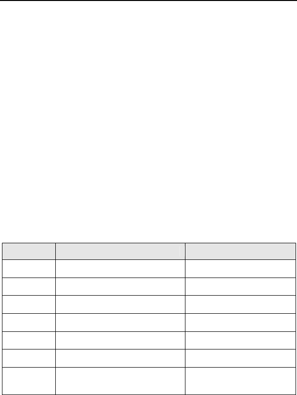
LAUNCH X-431 Throttle User Manual
79
11 Batterybox (Toolbox)
11.1 Product Summary
X-431 Throttle provides an optional function of automotive battery test, which
adopts the latest state-of-the-art conductance testing technology in the world
and can test vehicle’s battery status. Two testing environments (Inside the
Vehicle and Outside the Vehicle) are available and applicable to battery test. In
addition to battery test, charging system and actuation system test can be done
while Inside the Vehicle is selected.
It supports various battery standards and specifications, including CCA, DIN,
IEC, EN, JIS, SAE and GB etc. It is specifically designed to help car owner,
repair workshop, battery factory use battery test instrument properly and
determine whether the battery is normal or not.
Battery test aims to check starting plumbic acid storage batteries for vehicles,
ship, boats and aviations, etc. It can test all kinds of batteries complying with
CCA, DIN, JIS, EN, GB and SA standards. For detailed test standards, please
refer to Table 11-1.
Table 11-1 Test standard
Standards Standard (Full name) Test capacity range
CCA Battery Council International 100~1700
DIN Deutsche Industry Normen 100~1200
JIS Japanese Industry Standard 26A17~245H52
EN Europe Norm 100~1700
IEC National Electrical Commission 100~1200
GB Chinese National Standard 100~1200
SAE Society of Automotive
Engineers
100~1700

LAUNCH X-431 Throttle User Manual
80
11.2 Test Environment
11.2.1 Test environment
Inside the vehicle test indicates that the battery connects to loading devices,
such as engine, etc. After doing battery test, it can perform charging system and
actuation system test, which is proceeded as a whole simultaneously. Charging
system and actuation system test is not required but must not be performed
before battery test. Because it is difficult for vehicle technicians to judge where is
faulty exactly if they have the faintest idea of battery’s status itself.
Outside the vehicle test indicates that the battery is disconnected from all
loading devices on vehicles. Therefore, only battery test is supported in this
condition.
11.2.2 Battery status and description
There are mainly 5 states as follows:
No. States Descriptions
1 Good battery Indicates battery is normal.
2 Replace battery
Indicates that battery is aged or becomes rejected, or
battery life cycle approaches to be exhausted. In this
case, battery voltage appears to be normal, but
battery itself is not well, i.e. battery polarity board has
been completely vulcanized or aged. Please replace
battery immediately.
3 Good-recharge Stands for low battery. The battery is good itself.
4 Charge-retest
It is better for a few batteries to be fully charged
before testing in order to avoid judging in error under
special conditions.
5 Bad cell
Indicates one of the battery cells is bad and cannot
work normally, but for which one is bad, it can’t be
verified. In this case, battery voltage is generally lower
than 11V, mainly resulting from internal circuitry
damage, such as short circuit, open circuit, dummy
weld etc.
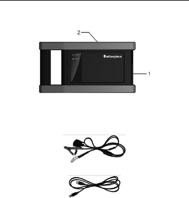
LAUNCH X-431 Throttle User Manual
81
11.3 Batterybox Structure & Accessories
11.3.1 Batterybox structure
Fig.11-1 Batterybox structure diagram
1. Battery connector: Connect to vehicle’s battery for battery test.
2. B type USB terminal: Connect to the X-431 Throttle tablet with USB cable.
11.3.2 Test accessories
Fig. 11-2 Kelvin clip
Fig. 11-3 A/B cable
11.4. Connections & Operations
11.4.1 Connection
Connect one end of the A/B cable to the B type USB terminal of the batterybox,
and then connect the other end to the USB port of X-431 Throttle tablet. This
connection applies to outside the vehicle test and inside the vehicle.
Notes:
1. Wait about 10 seconds and begin to communicate since the batterybox needs to
initialize after connection is complete, otherwise, communication may fail.
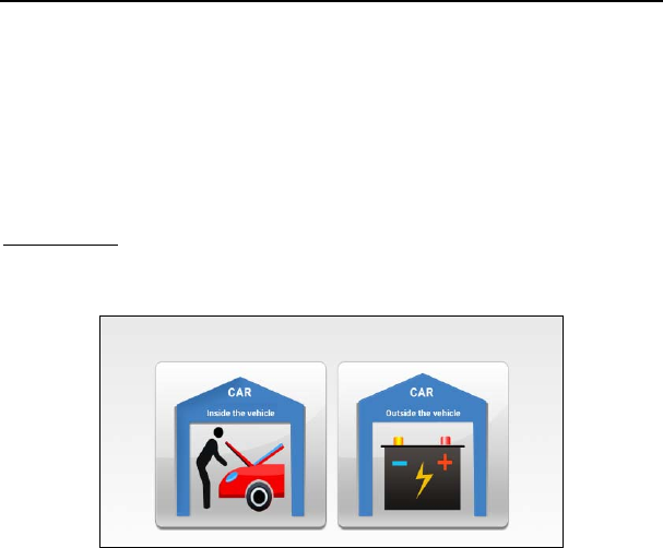
LAUNCH X-431 Throttle User Manual
82
2. Red lamp on the batterybox means it has been successfully powered up; If the green
light is always on, it indicates the clip is well connected; while the green light blinks,
it indicates that the clip has poor contact. Do not perform any test until the clip and
A/B cable are properly connected.
11.4.2 Inside the vehicle test
Battery test and charging system & actuation system test can be done in this
mode.
1. Battery test
Enter battery test main menu, and select a desired test environment as shown in
Fig. 11-4.
Fig. 11-4
Notes: The sequences of inside the vehicle and outside the vehicle test are almost the
same, but under inside the vehicle condition, all loads in vehicles must be powered off
for getting an exact test value.
1. Firstly, the system detects whether floating electricity exists or not before
testing. If yes, turn on the headlamp to remove it. Otherwise, the system
starts test program directly.
2. Tap [Inside the vehicle], the system starts detecting floating electricity
automatically. If floating electricity is detected, it will prompt you to turn on the
headlamp.
3. Follow the on-screen instructions to turn on headlamp, the system starts
removing floating electricity.
4. Once the floating electricity is removed, a prompt message box “The floating
electricity has been removed, please turn off the headlamp to continue the
testing” will appear on the screen.
5. Follow the on-screen instructions to turn off the headlamp and tap [OK], the
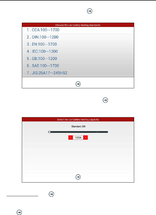
LAUNCH X-431 Throttle User Manual
83
system will continue the testing. Tap , it will enter testing standard
selection screen.
Fig. 11-5
6. Select a testing standard except for JIS and tap , a screen similar to Fig.
11-6 will appear. Users can adjust capacity size by tapping on < or > or by
dragging the slider on the bar.
Fig. 11-6
If JIS is selected, tap , the system will enter Select testing capacity screen.
Users can select corresponding standard capacity value according to battery
model marked on battery.
7. Tap and the testing result will appear on the screen.
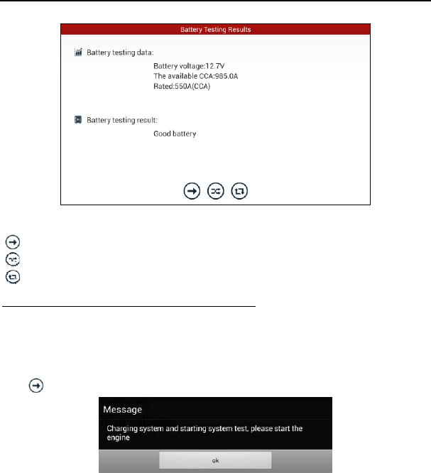
LAUNCH X-431 Throttle User Manual
84
Fig. 11-7
[]: Tap it to perform the charging system and starting system test.
[]: Tap to test it again.
[]: Tap it to reset the test.
2. Charging system and starting system test
While performing this test, the battery’s charging voltage value and starting
voltage can be obtained in case of engine starting and accelerating. Based on
the data, the system will judge whether battery’s charging and actuation status is
normal or not.
Tap in Fig. 11-7, a dialog box will pop up as Fig. 11-8.
Fig. 11-8
After detecting engine starting, follow the instructions on the screen to increase
the speed.
The system begins to receive test data information after acceleration was
detected, as shown in Fig. 11-9.

LAUNCH X-431 Throttle User Manual
85
Fig. 11-9
Tap [OK], test data will be shown on the screen.
Notes: It is unnecessary to perform charging system and start system test after finishing
battery test, but battery test must be done before undergoing charging system and
starting system test.
11.4.3 Outside the vehicle test
It only applies to battery test and detecting floating electricity will be ignored
while performing battery test.
On Fig. 11-4, tap [Outside the vehicle] to select battery test standard.
The following operation steps are identical to Steps 6~7 in Chapter 11.4.2
Battery test. Please refer to it for details.
11.5 Precautions On Battery Test
For the purpose of getting accurate test results, unless otherwise special
required, all loads need to be power off such as headlamp, engine etc. before
testing battery.
The operating time required for charging system and actuation system test
varies from person to person. If the engine does not start or accelerate within 30
seconds, the system will prompt you “receiving timeout” and return to the initial
status.
Whether Engine is off or not has no influence on charging and actuation test
result after increased speed is detected, but other loads need to be powered off.
The accuracy of battery voltage, charging voltage, start voltage is 0.01V in test
results; CCA (Cold Cranking Amps) precision is 5CCA.
Generally, charging voltage value is greater than starting voltage.
Charging voltage range is as follows: 13.8--14.5V for domestic vehicle;
13.3--15.5V for imported vehicles. The voltage varies with different car models,
so you have to judge based on related vehicle models. In general, the DC
voltage is stable, but it also varies with different revolution speed.
Starting voltage range: The value higher than 9.6V is regular, otherwise it is too
low. Due to different situations, whether the starting voltage is higher or not does

LAUNCH X-431 Throttle User Manual
86
not mean the vehicles or batteries are faulty. For detailed faults, other special
equipments are needed. To validate the accuracy of the value, the best method
is to collect the signals of starting and charging voltage and observe it on an
oscillometer.
Generally, the voltage is lower than 11V for the bad cell battery, but it is possible
that the battery is completely exhausted or has a serious low capacity. In this
case, just recharge your battery. Bad cell always happens when the loads on a
stopping vehicle are turned on for a long time.
Please note that it is normal for quick detecting of “Increase speed” because it
follows the theory of detecting “Increase speed”: If the detected voltage is higher
than the previous battery test voltage, the system will prompt you a message of
“Engine has been speeded”
It has no influence on test result in the event that engine’s output voltage or
engine revolution is not very stable. No matter whether the vehicle is accelerated
or not, the output voltage only differs within 0.2V.
While doing inside the vehicle test, Kelvin clip is always found to be in poor
contact. To remain it in good contact, please shake it several times before
testing. Take down the battery connector, and test it again, the value probably
varies. The deviation may arise from battery connector.
Pay more attention to connect the clip. The battery poles connect with conductor,
which makes the clip has a poor connection when testing battery. A tolerance of
dozens of CCA occurs if the clip is out of position, or oil, dust attaches on the
pole. The gear and main body of clip should be fully matched with battery poles.
Notes:
1. Battery poles inside the vehicle are enveloped by connectors, which may produce
some errors for test results. The tolerance results from the resistance of connectors.
The greater the resistance value is, the greater the tolerance becomes. But generally,
the tolerance does not affect the test conclusion.
2. Testing the battery separately generates an exact test result. The battery box is a
very useful auxiliary tool for quick test. If any problems were found, test it
separately for getting an exact test result.

X-431 Throttle User Manual
87
12 Oscilloscope (Toolbox)
12.1 Introduction
The Scopebox is an optional add-on module of X-431 Throttle, including
automotive oscilloscope and automotive ignition waveform.
Automotive oscilloscope can make the auto repair technician quickly judge the
faults on automotive electronic equipment and wiring, and the oscilloscope
sweep speed is far greater than the signal frequency of such vehicles, usually
5-10 times of the measured signal. The automotive oscilloscope not only can
quickly acquire the circuit signal, but also can slowly display the waveform to
observe and analyze. It can also record and store the tested signal waveform
which can be recalled to observe for the fast signal, having great convenience to
failure analysis. Either high-speed signal (e.g.: Injection nozzle, intermittent fault
signal) or the slow-speed signal (e.g. the throttle position change and the oxygen
sensor signal) can be observed through automotive oscilloscope in an
appropriate waveform.
The electronic signal can be compared and judged via measuring five
parameters indexes. The five parameters are the amplitude (the maximum
voltage of signal), the frequency (the cycle time of signal), the shape (the
appearance of signal), the pulse width (the duty cycle or the time range of signal),
and the array (the repetition characteristic of signal), which can be tested,
displayed, saved by the automotive oscilloscope. Via the waveform analysis can
further detect the circuit fault on sensors, actuators, circuits, and electronic
control units, etc.
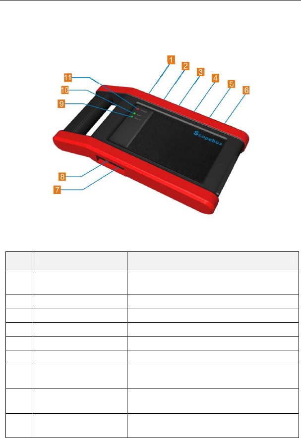
X-431 Throttle User Manual
88
12.2 Structure & Accessories
12.2.1 Scopebox structure
Fig 12-1 Scopebox Structure Diagram
Table 12-1 shows the ports and indicators for the Scopebox.
No. Name Description
1 Fixed signal generator Generate a square signal with fixed 1K
frequency.
2 CH1 Channel 1
3 CH2 Channel 2
4 CH3 Channel 3
5 CH4 Channel 4
6 External trigger External trigger signal
7 B-shaped USB
interface
Connect main unit via USB cable as
separated individual USB devices.
8 Power interface Connect to power supply via the power
adapter.
9 Communication
indicator It blinks in process of data communication.
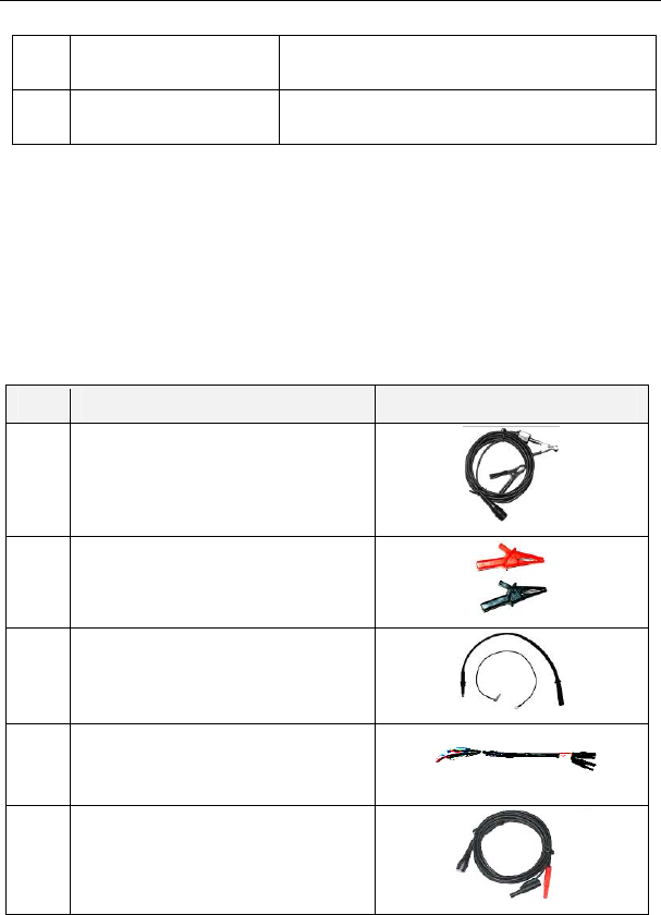
X-431 Throttle User Manual
89
10 Running indicator It remains steady green after the Scopebox
is running.
11 Power indicator It keeps steady red after the Scopebox is
powered on.
12.2.2 Scopebox accessories
The Scopebox includes the secondary pickup cable for 4-channel oscilloscope,
crocodile clips for 4-channel oscilloscope, etc. See Table 12-2.
As the product configuration can be different, the accessories included with the
product may differ from the accessories listed on this manual. Please see the
packing list attached to the product for the detailed accessories.
Table 12-2 Accessory checklist
No. Name Picture
1 Secondary ignition pickup for
4-channel oscilloscope
2 Crocodile clips for 4-channel
oscilloscope
3 Direct ignition extension cable
4 6-way universal guide line for
4-channel oscilloscope
5 BNC to 4mm connector test cable
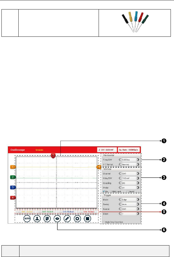
X-431 Throttle User Manual
90
6 Pin connector suite for 4-channel
oscilloscope
12.3 Connection & Initial Use
12.3.1 Connection
The Scopebox should work with the X-431 Throttle tablet.
1. Firstly, power on the X-431 Throttle tablet.
2. Then plug one end of ground cable of the Scopebox into external trigger
channel (GND), and the other end should be grounded.
3. Connect one end of probe cable to the CH1, CH2, CH3, or CH4 on the
Scopebox, and the other end to related signal terminal.
Warning: Please use the specific capacitance probe when diagnosing the ignition high
voltage line. Never connect the Scopebox to the ignition secondary circuit directly.
12.3.2 Initial interface introduction
Fig. 12-2 displays the initial interface of the Scopebox.
Fig. 12-2
No. Descriptions
X-431 Throttle User Manual
91
1 Signal display area
2 Horizontal Settings: Controls the time base.
3 Vertical Settings: Controls the amplitude of the displayed signal.
4 Trigger Settings: Controls the start event of the sweep.
5 Channel Selection Button
6
Function Menu
[Auto]: It indicates auto trigger setting.
[Ref]: There are expert reference and base reference available.
Expert reference enables you to recall your customized expert
database, whereas base reference provides automatic pre-setting
function of specialized sensors.
[File]: Provides save snapshot, snapshot manager, waveform
record and waveform replay.
[View]: Calibration and display settings are available.
[Measure]: Includes signal source measurement, horizontal
measurement, vertical measurement and clear measurement.
[Settings]: Shows/hides the parameter settings area including
horizontal settings, vertical settings and trigger settings.
/ [Start/Stop]: Starts/stops collecting waveforms.
12.4 Operations
12.4.1 Channel selection and attributes setting
<1> Channel selection
There are two ways available for channel selection:
A. Select from the channel tab shown at the bottom of the waveform display area
B. Select from Vertical settings
Note: For better comparison and identification, each channel and waveform are marked
in different colors.
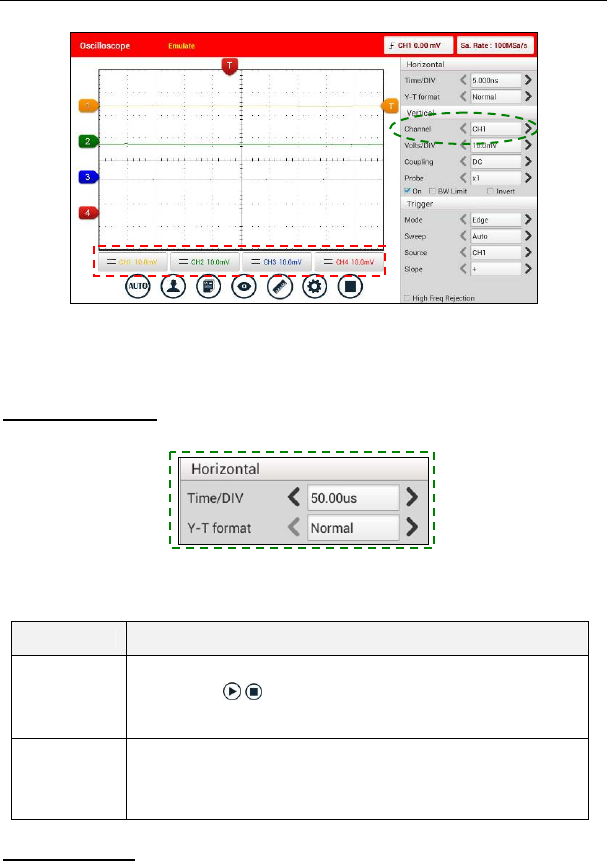
X-431 Throttle User Manual
92
Fig. 12-3
<2> Channel attributes & trigger setting
Channel attributes can be set via horizontal settings and vertical settings.
Horizontal Settings
User can make some settings directly by tapping < or > next to options.
Fig. 12-4
Options descriptions:
Menu Comments/Settings
Time/DIV
Horizontal scale. If the waveform acquisition is stopped
(using the / button), the Time/DIV selector expands
or compresses the waveform.
Y-T format
The conventional oscilloscope display format. It shows the
voltage of a waveform record (on the vertical axis) as it
varies over time (on the horizontal axis).
Vertical Settings
The trigger determines when the Scopebox starts to acquire data and display a
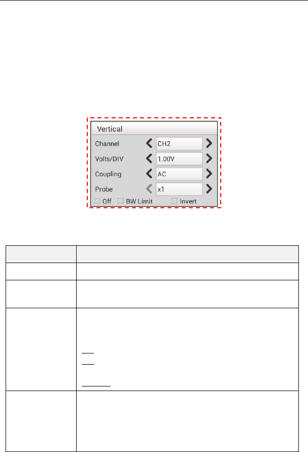
X-431 Throttle User Manual
93
waveform. When a trigger is set up properly, it can convert unstable displays or
blank screens into meaningful waveforms.
When the Scopebox starts to acquire a waveform, it collects enough data so that
it can draw the waveform to the left of the trigger point. The Scopebox continues
to acquire data while waiting for the trigger condition to occur. After it detects a
trigger, the Scopebox continues to acquire enough data so that it can draw the
waveform to the right of the trigger point.
User can make some settings directly by tapping < or > next to options.
Fig. 12-5
Options descriptions:
Menu Comments/Settings
Channel To select the channel source.
Volts/DIV It is defined as “Volts/Division” and mainly used to
change the resolution.
Coupling
Trigger coupling determines what part of the signal
passes to the trigger circuit. AC, DC and Ground are
included:
AC: Blocks the DC component of the input signal.
DC: Passes both AC and DC components of the input
signal.
Ground: Disconnects the input signal.
Probe
When using a probe, the Scopebox allows you to select
the attenuation factor for the probe. The attenuation
factor changes the vertical scaling of the Scopebox so
that the measurement results reflect the actual voltage
levels at the probe tip.
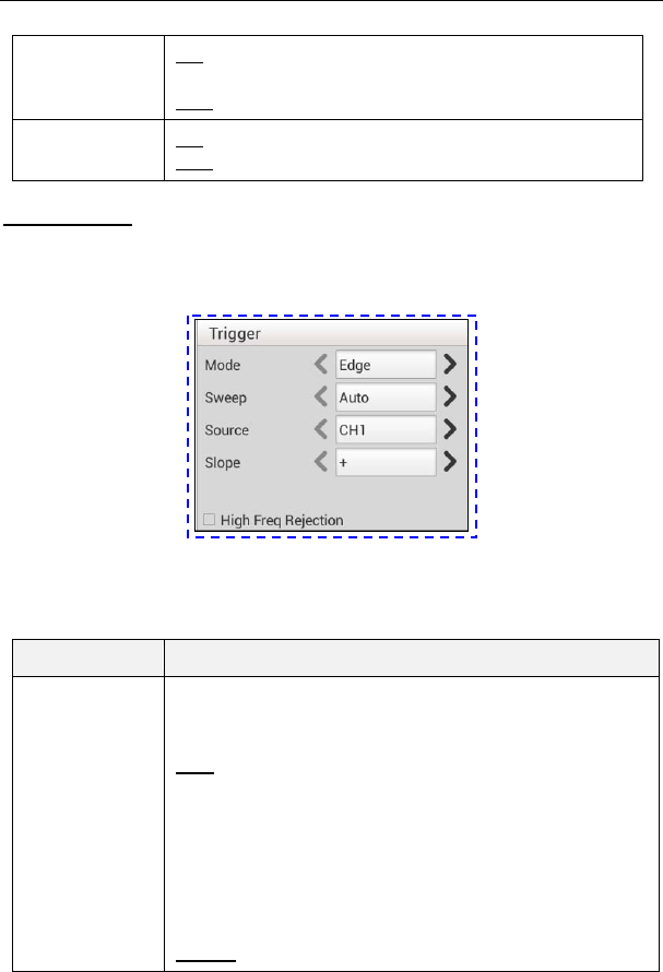
X-431 Throttle User Manual
94
BW Limit
ON: Limits the channel bandwidth to 20MHz to reduce
display noise.
OFF: Get full bandwidth.
Invert ON: Turn on the invert function.
OFF: Restore to the original display of the waveform.
Trigger setting
Trigger indicates that when certain waveform meets the conditions that are
predefined according to the requirements, the Scopebox acquires the waveform
and its adjacent section, and then presents it on the screen.
Fig. 12-6
1) If Edge trigger is selected (An edge trigger determines whether the Scopebox
finds the trigger point on the rising or the falling edge of a signal.):
Menu Comments/Settings
Sweep
The sweep mode determines how the Scopebox behaves
in the absence of a trigger event. The Scopebox provides
three trigger modes: Auto, Normal, and Single.
Auto: It allows the Scopebox to acquire waveforms even
when it does not detect a trigger condition. If no trigger
condition occurs while the Scopebox is waiting for a
specific period, it will force itself to trigger.
When forcing invalid triggers, the Scopebox can not
synchronize the waveform, and then waveform seems to
roll across the display. If valid triggers occur, the display
becomes stable on the screen.
Normal: This mode allows the Scopebox to acquire a

X-431 Throttle User Manual
95
waveform only when it is triggered. If no trigger occurs,
the Scopebox keeps waiting, and the previous waveform,
if any, will remain on the display.
Single: In this mode, it only acquires the waveform that
generates for the first time the trigger conditions are met,
and then stops after finishing capture.
Source Select which channel as trigger signal.
Slope + : Trigger on rising edge
- : Trigger on falling edge
High Freq
Rejection
Reject high frequency signals when selected.
2) If Pulse Width trigger is selected (Pulse trigger occurs according to the width
of pulse. The abnormal signals can be detected through setting up the pulse
width condition):
Menu Comments/Settings
Sweep
The sweep mode determines how the Scopebox
behaves in the absence of a trigger event. The Scopebox
provides three trigger modes: Auto, Normal, and Single.
Auto: It allows the Scopebox to acquire waveforms even
when it does not detect a trigger condition. If no trigger
condition occurs while the Scopebox is waiting for a
specific period, it will force itself to trigger.
When forcing invalid triggers, the Scopebox can not
synchronize the waveform, and then waveform seems to
roll across the display. If valid triggers occur, the display
becomes stable on the screen.
Normal: This mode allows the Scopebox to acquire a
waveform only when it is triggered. If no trigger occurs,
the Scopebox keeps waiting, and the previous waveform,
if any, will remain on the display.
Single: In this mode, it only acquires the waveform that
generates for the first time the trigger conditions are met,
and then stops after finishing capture.
Source Select which channel as trigger signal.
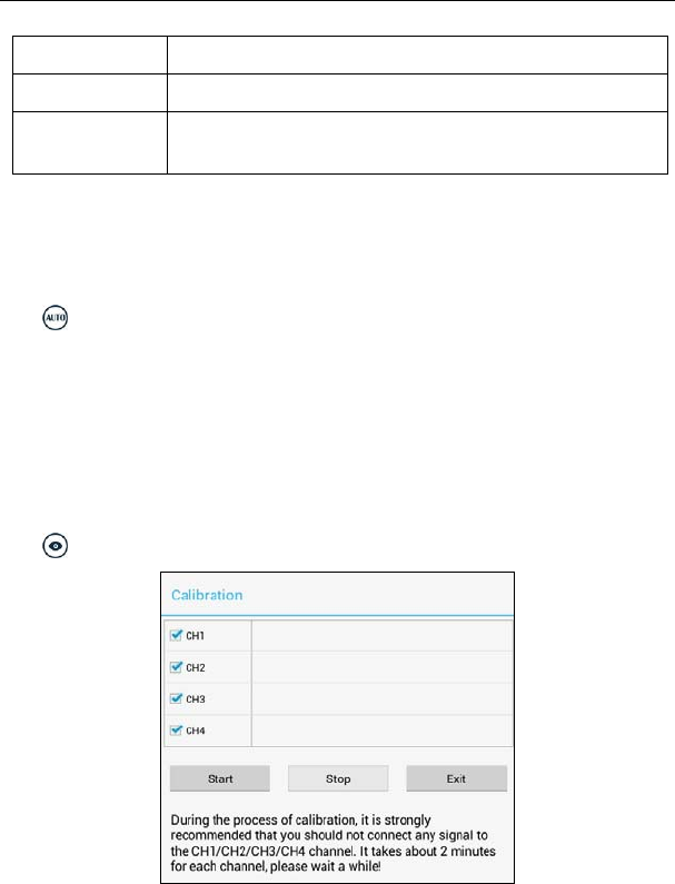
X-431 Throttle User Manual
96
Condition To select pulse condition.
Pulse Width Set required pulse width.
High Freq
Rejection
Reject high frequency signals when selected.
12.4.2 Auto
The Scopebox has an Auto feature that sets up the Scopebox automatically to
display the input signal in a best fit.
Tap , the Scopebox may change the current settings to display the signal. It
automatically adjusts the vertical and horizontal scaling, as well as the trigger
coupling, position, slope, level and mode settings.
12.4.3 View Settings
<1> Calibration
This option adjusts the Scopebox’s internal circuitry to get the best accuracy.
Use this function to calibrate the Scopebox’s vertical and horizontal systems.
Tap and then tap [Calibration], a dialog box similar to Fig. 12-7 will appear.
Fig. 12-7
Check the box before the channel to select it. To deselect it, just uncheck it. After
choosing the desired channel(s), tap [Start] to start calibration and [Start] button
will be temporarily invalid during calibrating. Tap [Stop] to stop calibrating. Once
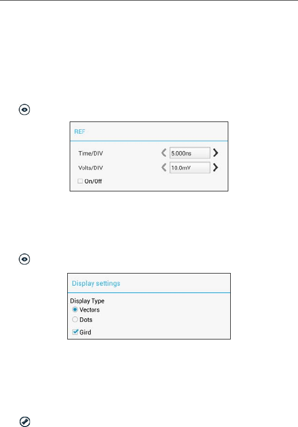
X-431 Throttle User Manual
97
it becomes active, it indicates calibration has completed.
Note: In process of calibration, make sure CH1/CH2/CH3/CH4 has no signal input.
Moreover, calibration may take several minutes and please be patient to wait.
<2> REF settings
Reference waveforms are saved waveforms to be selected for display. The
reference function will be available after saving the selected waveform to
non-volatile memory.
Tap and then [REF] to enter the REF setting screen.
Fig. 12-8
Tap < or > to select the desired reference value for time/DIV and volts/DIV. To
show or hide the REF, just check/uncheck the box before On/Off.
<3> Display settings
Tap and then [Display settings] to enter the setting screen.
Fig. 12-9
Select “Vectors” or “Dots” to display waveforms as vectors or dots. Check /
uncheck the box before Grid to turn on/off grid display.
12.4.4 Measure
<1> Channel source
Tap and then [Source], a screen similar to Fig. 12-10 will appear.
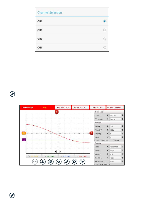
X-431 Throttle User Manual
98
Fig. 12-10
<2> Horizontal / Vertical measure
Horizontal Measure / Vertical Measure are used to measure voltage parameter
and time parameter respectively. Drag A line upwards or downwards to control
voltage. Move A line left or right to fine-tune timebase. A line is a solid line and B
line is a dotted line.
Tap and then [Horizontal Measure], a screen similar to Fig. 12-11 will
appear.
Fig. 12-11
Note: If no desired channel is selected, the system will take the current source as the
default channel.
<3> Clear measure
Tap and then [Clear Measure], the system will clear the measurement result
on screen.
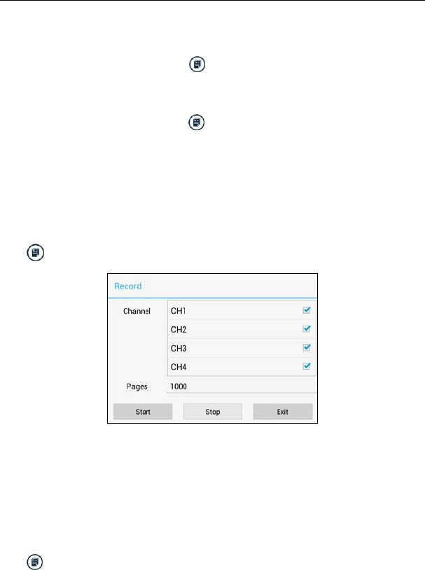
X-431 Throttle User Manual
99
12.4.5 File management
<1> Save snapshot
While viewing sampling data, tap and then [Save Snapshot] to store the
current screen.
<2> Snapshot manager
While viewing sampling data, tap and then [Snapshot Manager] to enter.
View, delete and edit operations are supported.
<3> Record waveform
This function is used to record input waveforms that are acquired by the
Scopebox at a specific period, and save it as waveform file which can be
recalled in future.
It can be performed only when the Scopebox is collecting data in Normal mode.
Tap , then select [Record] from the pop-up menu to start recording.
Fig. 12-12
Tap [Start] to start recording with a minimum record length of 10 frames, and
[Stop] to stop recording. While recording, the recorded pages will be shown on
the screen.
<4> Load waveform for playback
The Import function enables you to import the stored waveform file for playback
and review. During replaying, the Scopebox stops collecting data automatically.
Tap , then select [Waveform replay] from the pop-up menu to enter:
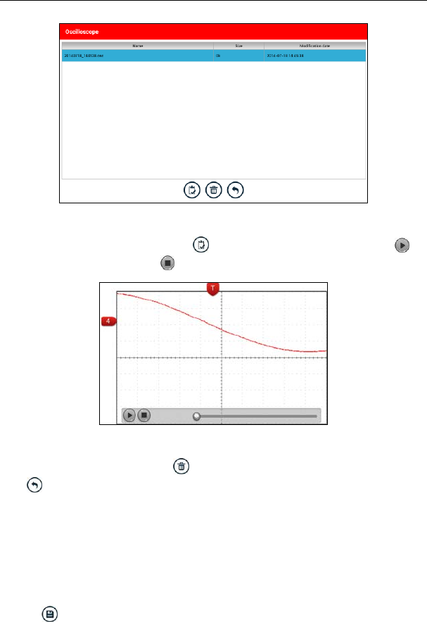
X-431 Throttle User Manual
100
Fig. 12-13
Select the file first, and then tap to open the waveform file. Tap to
starting the playback and tap to stop it.
Fig. 12-14
To delete the waveform file, tap .
Tap to return to the previous screen.
12.4.6 Expert reference
<1> Expert Reference
By default, it appears blank. As a matter of fact, Expert reference database is
generated by doing the following:
1. Open and edit a snapshot;
2. Select “Joint the expert database” (refer to the following illustration), and then
tap to save the waveform being displayed on the screen as REF.
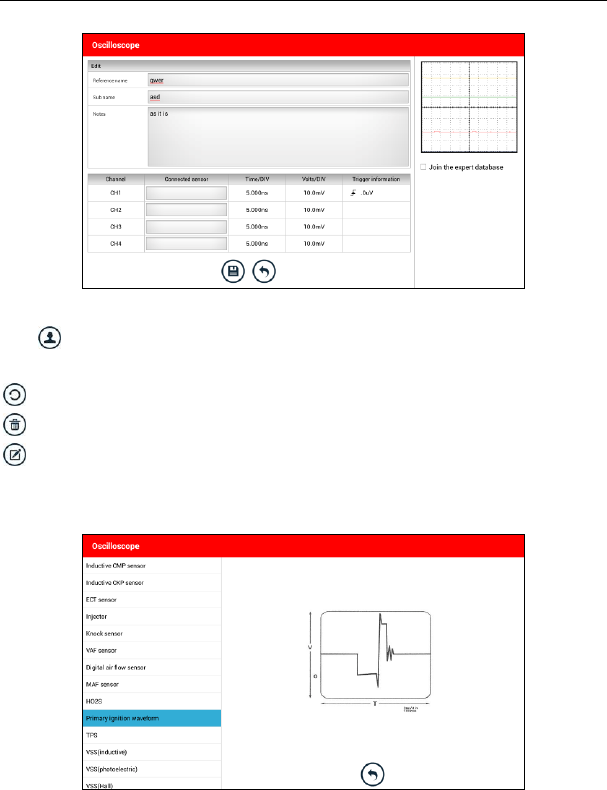
X-431 Throttle User Manual
101
Fig. 12-15
Tap and then [Expert Reference] to enter, the following operation can be
done:
: To load and recall the selected file.
: To delete the selected file.
: To edit the selected file.
<2> Base Reference
Preset waveforms of some sensors are available for your reference.
Fig. 12-16

X-431 Throttle User Manual
102
13 Automotive Ignition waveform
The ignition system is the system which has greatest impact on the
performances of gasoline engine, as the statistical data shows that nearly half of
the failures are caused by poor work of electrical system. And the performance
tests of engine often start from the ignition system. Nowadays ignition system
includes distributor and distributorless. Distributorless includes independent
ignition and simultaneous ignition.
1. Distributor ignition system i.e. contact breaker with contact-controlled ignition
system (commonly known as the platinum) and contact breaker with
noncontact-controlled ignition system combined with magnet, hall
components or infrared.
2. Independent ignition system: crankshaft sensor send out the ignition timing
signal and cylinder identification signal so that the ignition system can send
out ignition signal to specified cylinder in specified time, each cylinder has its
independent ignition coil.
3. Simultaneous ignition system: two cylinders share one ignition coil, when two
cylinder pistons reach top dead center at the same time (one is compression,
another is the exhaust), two spark plugs will be ignited at the same time, at
this time, the ignition for the former cylinder is in high-pressure low
temperature gas mixture, the ignition is valid, while for the latter one is in
low-pressure high temperature exhaust gas, the ignition is invalid.
X-431 Throttle can test and analyze the secondary signal for various engine
ignition systems.
13.1 Secondary-distributor ignition analysis
Connections: Plug the BNC end of secondary ignition pickup into
CH1/CH2/CH3/CH4 channel of Scopebox, then connect the high-voltage clip to
high-voltage line, and crocodile clips to ground.
Tips: Common ignition sequence (the specific sequence is subject to the actual engine
ignition sequence)
Four-stroke in-line four-cylinder: 1-2-4-3, or 1-3-4-2
Four-stroke in-line six-cylinder: 1-5-3-6-2-4, or 1-4-2-6-3-5
Four-stroke in-line eight-cylinder: 1-8-4-3-6-5-7-2
Five-cylinder: 1-2-4-5-3
V 6 engine: generally speaking, based on the person sitting on the driver cab, if
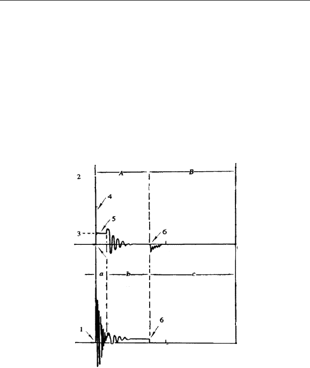
X-431 Throttle User Manual
103
the right side cylinder numbers on the right side, from the front to the back are as
follows: 1, 3, 5; and the cylinder numbers on the left side, from the front to the
back are as follows: 2, 4, 6; then the ignition sequence is: 1-4-5-2-3-6. If
the cylinder numbers on the right side, from the front to the back are as follows:
2, 4, 6; and cylinder numbers on the left side, from the front to the back are as
follows:1, 3, 5; then the ignition sequence is: 1-6-5-4-3-2.
Figure 13-1 below shows the normal ignition waveform of distributor ignition
system, the upper one is the secondary waveform, and the lower one is the
primary waveform.
The secondary waveform
A section is contact open period; B section is make contact period, which is the
magnetizing field of ignition coil.
Fig. 13-1
1) Contact break point: the primary circuit of ignition coil cut off, the secondary
voltage was sensed and increased sharply
2) Ignition voltage: secondary coil voltage overcome the damper of high voltage
line, the contact breaker gap and the spark plug gap to release magnetizing
energy, 1-2 section is the breakdown voltage
3) Spark voltage: For the capacitor discharge voltage
4) Ignition voltage pulse: For the charge and discharge sections

X-431 Throttle User Manual
104
5) Spark line: The inductance discharge process, i.e. the mutual inductance
voltage of ignition coil maintains the conduction of secondary circuit
6) Contact point close the current flow into primary coil, the primary coil
oscillates due to the mutual inductance.
Primary ignition waveform
Section a shows the voltage oscillation on the primary circuit due to the
magnetic induction of spark in the duration;
Section b shows the damped oscillation generated by remaining magnetic field
energy after the spark;
Section c shows the make contact magneting period of primary coil.
Seen from the waveform, the amplitudes of breaker contact closed angle, break
angle and breakdown voltage and spark voltage are very clear, besides, the
spark delay period and two oscillations can also be tested. For the ignition
system without faults, compared with the whole cycle, the contact closed angle
just 45%-50% (four-cylinder), 63%-70% (six-cylinder), or 64%-71%
(eight-cyliner); the breakdown voltage is over 15kv; the spark voltage is about
9kV, the spark period is greater than 0.8ms. If these values or waveform are
abnormal, it means there is fault or the system needs to be adjusted.
13.2 Secondary-simultaneous ignition analysis
Connections: Plug the BNC end of secondary ignition pickup into
CH1/CH2/CH3/CH4 channel of Scopebox, then connect the high-voltage clip to
high-voltage line, and crocodile clips to ground.
Connection as shown in figure 13-2:
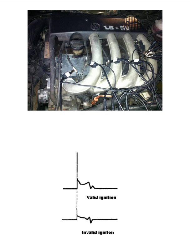
X-431 Throttle User Manual
105
Fig. 13-2
Fig. 13-3 below shows the valid and invalid ignition waveforms. Under the
working status of valid ignition, the breakdown voltage and spark voltage are
higher because the cylinder is filled with fresh combustible mixture gas, which
has a lower ionization level and vice versa.
Fig. 13-3
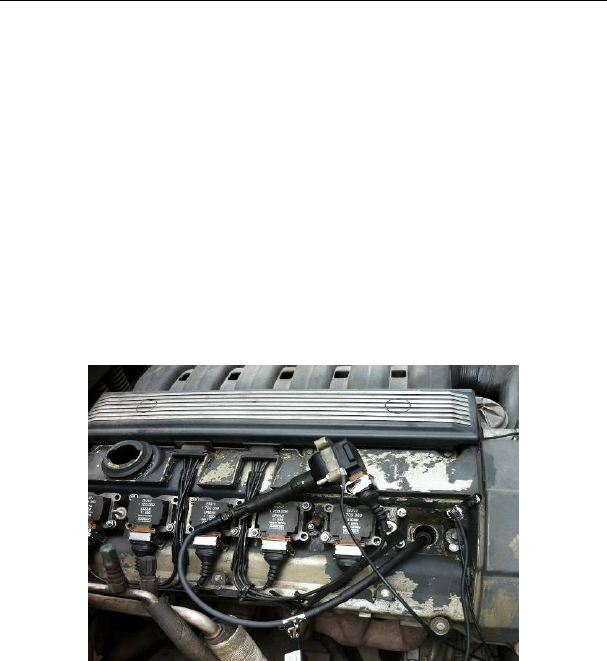
X-431 Throttle User Manual
106
13.3 Secondary-direct ignition analysis
Connection:
1) When the high-voltage wire is exposed, plug the BNC end of secondary
ignition pickup into CH1/CH2/CH3/CH4 channel of Scopebox, then connect
the high-voltage clip to high-voltage line, and crocodile clips to ground.
2) If no high-voltage wire exposes, dismantle ignition coil of tested cylinder and
use direct ignition extension cord. Connect one end to ignition coil which
should be grounded via direct ignition grounding wire, and insert the other
end into cylinder to joint with spark plug. Then plug the BNC end of
secondary ignition pickup into CH1/CH2/CH3/CH4 channel of Scopebox,
then connect the high-voltage clip to high-voltage line, and crocodile clips to
ground.
Connections are shown in Fig. 13-4:
Fig. 13-4
Fig. 13-5 shows the normal secondary (the upper one) and (the lower one)
primary ignition waveform of direct ignition system. Beause the on/off of primary
circuit is not opening/closing of mechanical contact, but the conduction of
transistor. The primary voltage has no obvious oscillations within the duration,
but the voltage increases during the magnetization process due to current
limiting, and this change can cause corresponding fluctuations of secondary
voltage line as a result of induction of ignition coil.
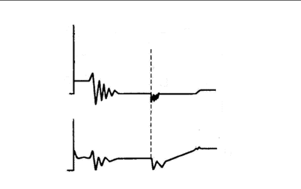
X-431 Throttle User Manual
107
Fig. 13-5
13.4 Waveform analysis mode
The ignition secondary single-cylinder waveform test is mainly used to:
a. Analyze the ignition dwell angle of single cylinder.(ignition coil charging time)
b. Analyze the capability of ignition coil and secondary high tension circuit (from
ignition line to ignition voltage line).
c. Find the improper mixture A/F ratio of single cylinder (from combustion line).
d. Analyze the capability of capacitance (platinum or ignition system).
e. Find the spark plug that causes misfire of the cylinder (from combustion line).
This test can provide very meaningful information about the combustion quality
for each cylinder. If necessary, this test can also be performed during driving.
Since the secondary ignition waveform is significantly affected by different
engines, fuel systems and ignition conditions, it is useful for detecting the faults
of engine mechanical parts, fuel system components, and ignition system
components. Different parts of the waveform can specify that some components
and systems on the specific cylinder have faults. Refer to the instructions for
various parts of waveform for the related component working status of specific
waveform section.
Test methods and conditions:
Start the engine or drive the vehicle according to the driving performance fault or

X-431 Throttle User Manual
108
poor ignition, etc. Confirm the consistence of judgment standard (the amplitude,
frequency, shape and pulse width, etc., for each cylinder), check the fault of the
waveform for corresponding components.
Waveform results: observe the ignition coil at the beginning of charging, the
relative consistent falling edge represents the dwell angle and ignition timing of
each cylinder are precise.
Ignition line:
Observe the height consistence of flashover voltage. Too high flashover voltage
(even out of the oscilloscope screen) represents a high resistance existed in the
ignition secondary circuit (for example, open circuit, or damaged spark plug or
high voltage line, or too large time gap on spark plug), while the too short
sparking voltage represents the resistance of ignition secondary circuit is lower
than normal value (due to pollutant and broken spark plug or the high voltage
line of spark plug has electrical leakage, etc.).
Spark or combustion voltage:
Observe the consistence of spark or combustion voltage, as it represents the
consistence of spark plug and the air-fuel ratio of each cylinder. In case that the
mixing ratio is too lean, the combustion voltage will be lower than normal value.
Combustion line:
Observe the spark or the combustion line which shall be clean with few clutter,
as lots of clutter indicates the cylinder has poor ignition due to ignite too early,
damaged nozzle, pollutant spark plug, or other reasons. The duration of
combustion line indicates the mixing ratio of the cylinder is abnormal lean or rich.
Too long combustion line (usually greater than 2ms) represents the mixing ratio
is rich, whereas too short of combustion line (usually less than 0.75ms)
represents the mixing ratio is lean.
Ignition coil oscillation:
Observe at least two oscillation waveforms after the combustion line, which will
be better if more than three oscillation waveforms, as it represents the ignition
coil and capacitor (on Platinum or ignition system) are normal.
Primary voltage analysis
According to the faulty primary voltage waveform collected by the ignition
analysis, the related components and mechanical equipment status of ignition
system electrical circuit can be analyzed, which provides a reliable basis for the
adjustment and maintenance of power circuit to avoid the blind demolition.
The waveform shown on Fig. 13-6, appears a lot of clutter on the contact break
point, which is obviously caused by the serious erosion on contact break point. It
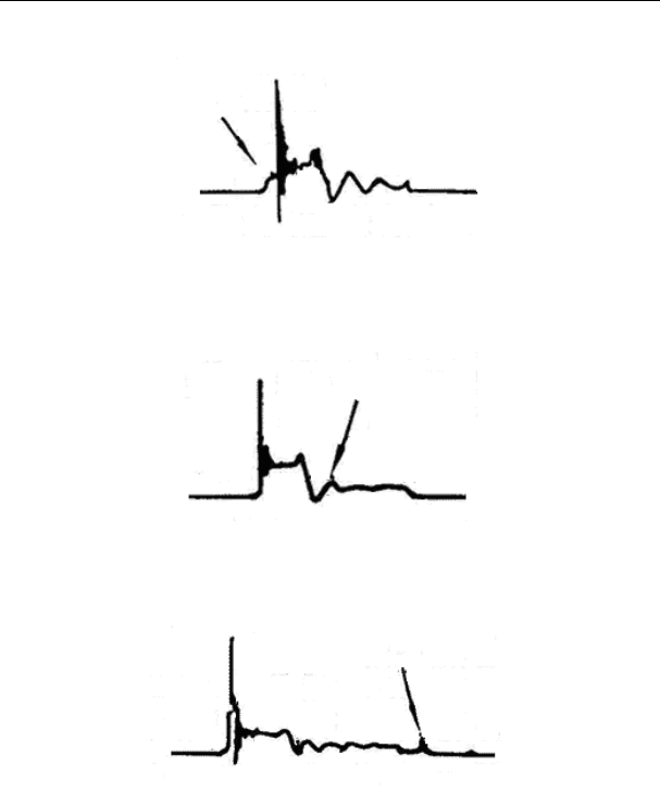
X-431 Throttle User Manual
109
can be verified via burnishing the contact or changing the circuit breaker.
Fig. 13-6
For the primary voltage waveform shown on Fig. 13-7, the damped attenuation
cycles obviously reduced on the spark period, the amplitude became lower,
which is evidently caused by capacitor leakage.
Fig. 13-7
The waveform on Fig. 13-8 shows the accidental pumping during contact closing
period. The irregular beating is caused by insufficient spring force.
Fig. 13-8
The curve on Fig. 13-9 shows the contact angle is too small during the
magnetizing period, which is caused by too large contact gap.
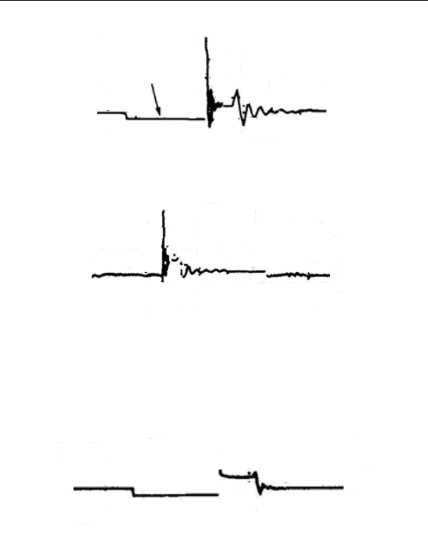
X-431 Throttle User Manual
110
Fig. 13-9
A lot of clutter will be displayed on the horizontal section of primary waveform if
contact has poor grounding, as shown below figure 13-10.
Fig.13-10
Fig. 13-11 shows the fault of low-voltage waveform in electronic ignition system.
The voltage does not rise during magnetizing, which indicates that the effect of
limitation of the circuit failed and no components on distributorless ignition
system can be adjusted. When this waveform is abnormal, you can only replace
the ignition coils, igniter, ignition signal generator and cam position sensor, etc.,
one by one, to find out the faulty component or module.
Fig. 13-11
The secondary waveform is also affected by the spark plug, the combustion
process, mixture gas composition, the engine thermal state of the ignition coil,
etc., which is more complicated. The following lists a large number of measured
secondary faulty waveform for reference. Since various factors lead to the
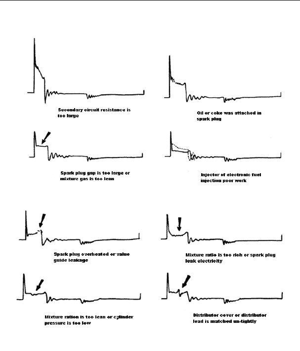
X-431 Throttle User Manual
111
failures, Fig. 13-12 just shows the major possible factors for the failures.
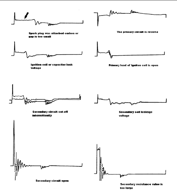
X-431 Throttle User Manual
112
Fig 13-12
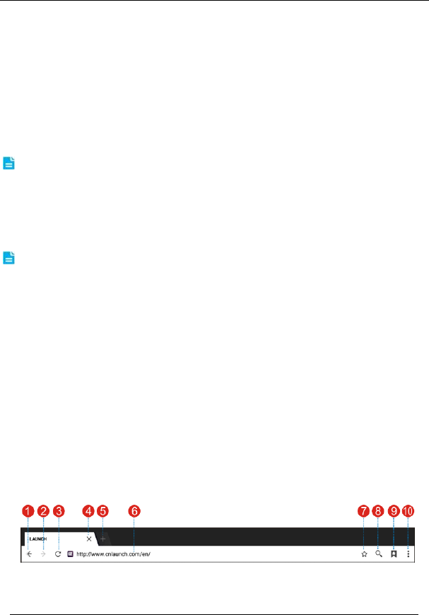
X-431 Throttle User Manual
113
14 Others
14.1 Email
The function allows you to send and receive email.
14.1.1 Configure an email account
Note: Before sending or receiving email, you have to set up an email account. In
addition, this function required a stable network connection.
1. On the home screen, tap Email.
2. Choose the desired email account type.
3. Input email address and password, tap “Next”.
Note: If “Manual setup” is selected, please consult your email service provider for
detailed parameter setting.
4. Follow the on-screen instructions to proceed until the system prompts you
that the account setup has been finished.
14.1.2 Add an email account
1. Tap Settings -> Accounts.
2. Tap Add account.
3. Choose the desired account type.
14.2 Browser
14.2.1 Open browser
On the home screen, tap Browser to launch the browser. You can choose the
desired homepage or input the website address to browse.
Fig. 14-1
1 Return to the previous page.

X-431 Throttle User Manual
114
2 Advance to the recently visited page.
3 Refresh the current page.
4 Close the current page.
5 Create a new tab.
6 Input a web address.
7 Add the current page as bookmark.
8 Open search bar.
9 Open bookmark list.
10 View more options.
14.2.2 Download files
Files, pictures, and applications can be downloaded from the website in browser.
For example:
Tap and hold a picture, then choose “Save image” from pop-up menu to
download it.
To download a link, tap and hold it, and then choose “Save link”.
To protect your X-431 Throttle and personal data, please download applications
from trusted sources. To configure it, tap Settings -> Security, and then slide
the Unknown sources switch to off.
14.3 Synchronization
You can transfer media files and APK between the PC and X-431 Throttle.
14.3.1 Connect to PC
1. Use the USB cable to connect the X-431 Throttle to your PC.
2. Swipe from the top, a message “Connected as a media device” appears.
14.3.2 Run on PC
Perform the following steps:
y Locate the new disc.
y Copy the files.

X-431 Throttle User Manual
115
14.3.3 Install an application
Do the following steps:
1. Tap Settings -> Security, and set the “Unknown sources” to ON, which
allows you to install apps from unknown sources.
2. A dialog box appears on the screen, tap “OK” to confirm.
3. Set the tool as “Connected as a media device”, and copy the APK file from
the PC to the tool.
14.4 Clear Cache
Doing so clears all browsing records and accounts and enables X-431 Throttle
to run smoothly and quickly.
1. Tap Settings -> Apps.
2. Tap and select “Sort by size” to arrange all applications in size order.
3. Tap certain application, then tap “Clear Cache” to release the space these
cache files are occupied.

X-431 Throttle User Manual
116
15 FAQ
1. Communication error with vehicle ECU?
Please confirm:
1) Whether the VCI is properly connected.
2) Whether the vehicle ignition switch is ON.
3) If all checks are normal, send vehicle year, make, model and VIN number to
us using Diagnostic Feedback feature.
2. Failed to enter into vehicle ECU system?
Please confirm:
1) Whether the vehicle is equipped with the system.
2) Whether the VCI is correctly connected.
3) Whether the vehicle ignition switch is ON.
4) If all checks are normal, send vehicle year, make, model and VIN number to
us using Diagnostic Feedback feature.
3. Can I use any other power adaptor other than the included power
adaptor to charge the handset?
No. Please use only the included power adaptor to charge the handset. We
assume no responsibility for damage or loss resulting from the use of the any
other adaptors.
4. How to save power?
¾ Please turn off the screen while X-431 Throttle keeps idle.
¾ Set a shorter standby time.
¾ Decrease the brightness of the screen.
¾ If WLAN connection is not required, please turn it off.
¾ Disable GPS function if GPS service is not in use.
5. How to do if the system runs slow?
In this case, please do the followings:
> Check all running applications and stop the unnecessary applications (Steps:
Settings -> Apps -> Running -> Tap the desired application and then tap “Stop”).
> Check all installed applications, remove the unnecessary applications (Steps:

X-431 Throttle User Manual
117
Settings -> Apps -> Downloaded -> Tap the desired application and then tap
“Uninstall”).
If all steps mentioned above are finished and the system still works slowly.
Please try to close the system and reboot your X-431 Throttle.
6. How to reset X-431 Throttle?
Resetting may cause data loss. Before doing so, please make sure important data
and information has been backed up.
Do the following to reset X-431 Throttle:
1. Tap “Settings” -> “Back & Reset”.
2. Tap “Factory data reset”.
3. Tap “Reset tablet”.
4. Tap “Clear all data” to start resetting until the tool automatically reboots.
7. The diagnostic application is failing.
1. Press the Home key on the tool.
2. Select “Settings”-> “Apps”.
3. Select the application name from the Apps list.
4. Select “Force Stop”, and then press “OK” to confirm.
5. Select “Clear Data”, and then press “OK” to confirm.

Warranty
THIS WARRANTY IS EXPRESSLY LIMITED TO PERSONS WHO PURCHASE
LAUNCH PRODUCTS FOR PURPOSES OF RESALE OR USE IN THE
ORDINARY COURSE OF THE BUYER’S BUSINESS.
LAUNCH electronic product is warranted against defects in materials and
workmanship for one year from date of delivery to the user.
This warranty does not cover any part that has been abused, altered, used for a
purpose other than for which it was intended, or used in a manner inconsistent
with instructions regarding use. The exclusive remedy for any automotive meter
found to be defective is repair or replacement, and LAUNCH shall not be liable
for any consequential or incidental damages.
Final determination of defects shall be made by LAUNCH in accordance with
procedures established by LAUNCH. No agent, employee, or representative of
LAUNCH has any authority to bind LAUNCH to any affirmation, representation,
or warranty concerning LAUNCH automotive meters, except as stated herein.
Disclaimer
The above warranty is in lieu of any other warranty, expressed or implied,
including any warranty of merchantability or fitness for a particular purpose.
Purchase Order
Replaceable and optional parts can be ordered directly from your LAUNCH
authorized tool supplier. Your order should include the following information:
• Order quantity
• Part number
• Part name
Customer Service
If you have any questions or comments please forward them to:
LAUNCH Tech USA
Product Support
Phone: 877-528-6249 xt: 4
E-mail: support@launchtechusa.com
Fax: 562-463-1590
Monday - Friday 5 am - 5 pm PST

Service & Repair
Phone: 877-528-6249 xt: 5
Monday - Friday 8 am - 5 pm PST
If your unit requires repair service, return it to the manufacturer with a copy of
the sales receipt and a note describing the problem. If the unit is determined to
be in warranty, it will be repaired or replaced at no charge. If the unit is
determined to be out of warranty, it will be repaired for a nominal service charge
plus return freight. Send the unit pre-paid to:
Attn: LAUNCH Tech USA
1820 South Milliken Ave.
Ontario, CA 91761
FCC Warning:
This device complies with part 15 of the FCC Rules. Operation is subject to the
following two conditions: (1) This device may not cause harmful interference,
and (2) this device must accept any interference received, including
interference that may cause undesired operation.
Any Changes or modifications not expressly approved by the party responsible
for compliance could void the user's authority to operate the equipment.
This equipment has been tested and found to comply with the limits for a Class
B digital device, pursuant to part 15 of the FCC Rules. These limits are
designed to provide reasonable protection against harmful interference in a
residential installation. This equipment generates uses and can radiate radio
frequency energy and, if not installed and used in accordance with the
instructions, may cause harmful interference to radio communications.
However, there is no guarantee that interference will not occur in a particular
installation. If this equipment does cause harmful interference to radio or
television reception, which can be determined by turning the equipment off and
on, the user is encouraged to try to correct the interference by one or more of
the following measures:
-Reorient or relocate the receiving antenna.
-Increase the separation between the equipment and receiver.
-Connect the equipment into an outlet on a circuit different from that to which
the receiver is connected.
-Consult the dealer or an experienced radio/TV technician for help.
The SAR limit of USA (FCC) is 1.6 W/kg averaged over one gram of tissue.
Device types X-431 THROTTLE (FCC ID: XUJPADV) has also been tested
against this SAR limit. The Max simultaneous SAR is 0.68 W/kg. This device
was tested for typical body-worn operations with the back of the handset kept
10mm from the body. To maintain compliance with FCC RF exposure
requirements, use accessories that maintain a 10mm separation distance
between the user's body and the back of the handset. The use of belt clips,
holsters and similar accessories should not contain metallic components in its
assembly. The use of accessories that do not satisfy these requirements may
not comply with FCC RF exposure requirements, and should be avoided.
For 5G frequency band, operations in the 5150-5250 and 5725-5850 band are
restricted to indoor usage only.
Any emission is maintained within the band of operation under all conditions of
normal operation. The max. frequency stability is less than 20ppm.