Launch Tech X631WAPR X-631+Probe User Manual
Launch Tech Co., Ltd. X-631+Probe
UserManual.wiki
>
Launch Tech
>
X631WAPR User Manual
User Manual
Navigation menu
Upload a User Manual
Namespaces
Wiki Guide
HTML
PDF
Info
Views
User Manual
Discussion / Help
Navigation

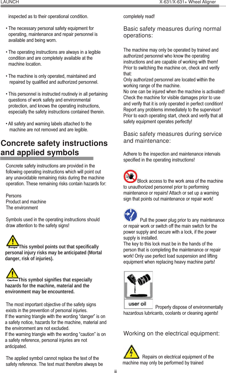

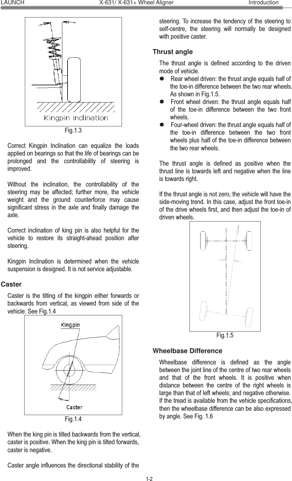
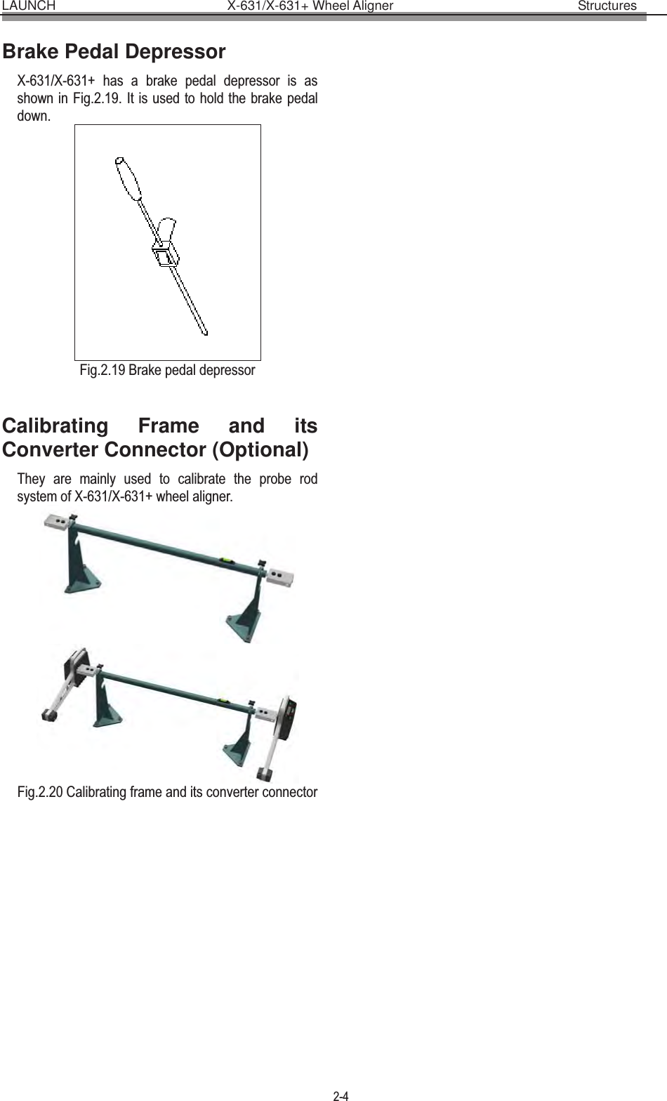
![LAUNCH X-631/X-631+ Wheel Aligner Structures 2-2 LCD display area has six functions: take the X-631 as an example. [Display start interface]: “Welcome to use X-631” is displayed on LCD as shown in Fig.2.4. Fig.2.4 [Display charging status]: “Battery Charging” is displayed on LCD as shown in Fig.2.5. It indicates that the battery is being charged. Fig.2.5 “Charge Finished!” is displayed on LCD as shown in Fig.2.6. It indicates that the battery charging is finished. Fig.2.6 Notes: When the characters of “>>>” are displayed on LCD, it indicates that the probe rod is being chargedĢWhen “=D-”is displayed, it indicates that the charging is finished, and the cables are connected, the probe rod is powered by the power supply from outside. [Display electric level]: “level” is displayed on LCD. It indicates that the level position adjustment is being performed, and the black float mark indicates the position of the bubble level as shown in Fig.2.7. Fig.2.7 The probe rod is level when the black float mark turns to “OK” as shown in Fig.2.8. Fig.2.8 [Display for run-out compensation]: To display the current compensation status of the probe rod: 0 indicates the run-out compensation operation should be started for the current probe rod. The interface is as shown in Fig.2.9. Fig.2.9 90,180, 270 and 360 indicates respectively the corresponding angles by which the tire should be rotated. The interface is as shown in Fig.2.10. Fig.2.10 After finishing the compensation operation for the probe rod, the level status of the probe rod will be displayed on LCD, and the run-out compensation indicator on the control panel of the probe rod will turn green. The interface is as shown in Fig.2.11. Fig.2.11 [Display probe rod measurement]: Real-time display Camber (C), Toe-in (T) and Battery electricity quantity (B) as shown in Fig.2.12. Fig.2.12 [Display probe rod status]: Display the position of probe rod and the electricity quantity of battery as shown in Fig.2.13. Fig.2.13](https://usermanual.wiki/Launch-Tech/X631WAPR/User-Guide-1779792-Page-12.png)
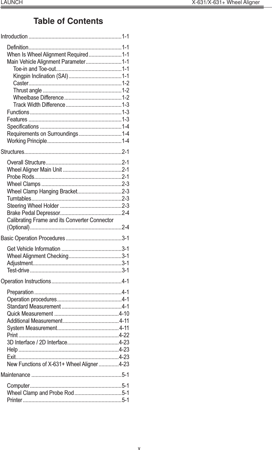
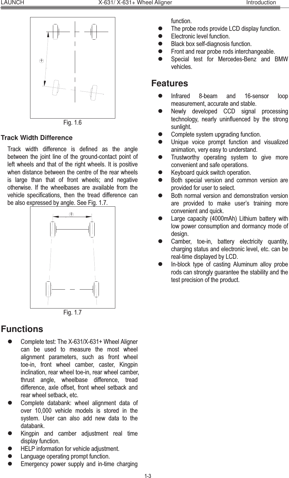
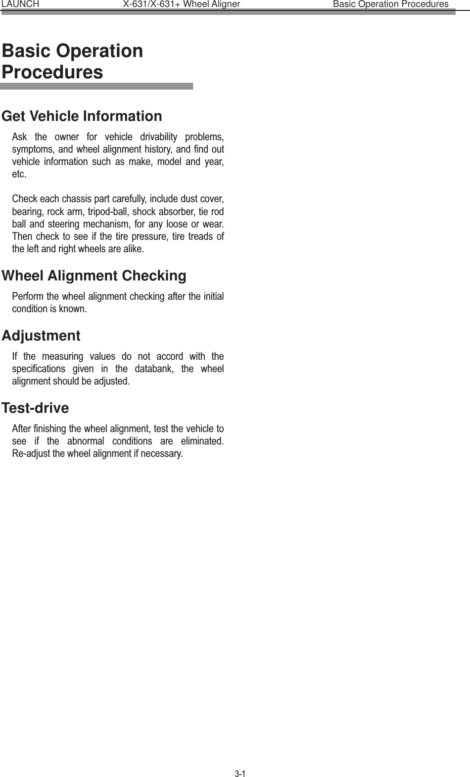
![LAUNCH X-631/X-631+ Wheel Aligner Structures 2-3 [Display Standby status]: “Stand By…” is displayed on LCD. It indicates that the probe rod is in standby mode for saving electricity. The standby mode can be switched to normal working mode as shown in Fig.2.14. Fig.2.14 Button area includes 5 buttons: [Backlight]: Key to switch on/off the backlight of LCD. [Next]: To perform the test according to the default sequence (Select Vehicle Model Run-out Compensation Kingpin Measurement Rear Axle Measurement Front Axle Measurement Print Report Form ) of the system. [Previous]: To return to the previous operating procedure during test. [Run-out compensation]: It is the special key-press for run-out compensation operation. [Power switch]: Switch on/off the battery power supply of the probe rod. There is a 9V power supply socket on the side wall of the probe rod box. It is used for charging the battery of the probe rod. When the electricity quantity of the battery is full, the charging circuit will automatically stop charging. Caution! Make sure to turn off the power of the probe rod before charging it. The probe rod is a precision component; please handle it with care to ensure measuring accuracy. Wheel Clamps X-631/X-631+ has 4 wheel clamps (see Fig.2.15). Turn the adjusting knob to adjust the span between wheel claws, and then attach the clamp to the wheel rim. Adjust the knob to make the wheel clamp fixed on wheel rim tightly. Use the wheel clamp tie to bind the wheel clamp and the wheel rim together. The installation of wheel clamp is crucial to the test result. The claws should be in even contact with the wheel rim without touching the lead weight. Avoid hitting during operation. Otherwise, distortion may be caused and the test result may be influenced. Fig.2.15 Wheel Clamp Hanging Bracket X-631/X-631+ wheel aligner is equipped with 4 wheel clamp hanging brackets as shown in Fig.2.16. Fig.2.16 After unpacking, it is necessary to install these 4 hanging brackets on left and right side wall of the cabinet. Turntables X-631/X-631+ has two mechanical turntables (standard configuration, see Fig.2.17). Fig.2.17 mechanical turntables When testing, the turntables should be placed at the front wheel position of vehicle on the lift. Use the lock pin to lock the turntable before driving the vehicle on. Pull out the lock pin after the vehicle is stopped and the front wheels are at the center of the turntables. While testing, try your best to keep the vehicle front wheel at the center of the turntable. Steering Wheel Holder X-631/X-631+ has a steering wheel holder as shown in Fig.2.18. Use the steering wheel holder to lock the steering wheel according to the tips on the screen. Fig.2.18 Steering wheel holder](https://usermanual.wiki/Launch-Tech/X631WAPR/User-Guide-1779792-Page-13.png)
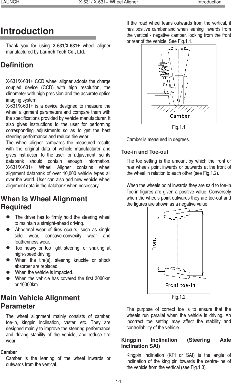
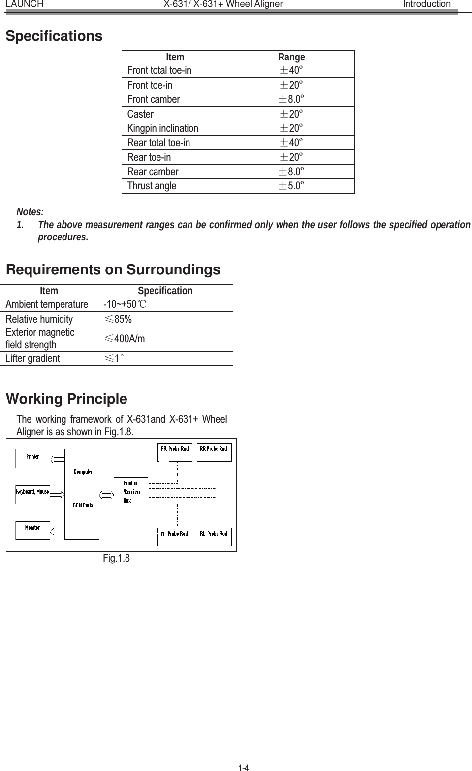
![LAUNCH X-631/X-631+ Wheel Aligner Operation Instructions 4-1 Operation Instructions Preparation I. Drive the vehicle onto the lift or over the pit, so that the front wheels are centered to the turntables; Apply hand brake to ensure safety. To prevent the turntable from turning, lock the turntables with the lock pins before driving the vehicle; release the lock pins after the vehicle is well-positioned. II. Ask the owner for vehicle drivability problems and symptoms, wheel alignment history, and find out vehicle information such as make, model and year, etc. III. Check each chassis part carefully, include dust cover, bearing, rock arm, tripod-ball, shock absorber, tie rod ball and steering mechanism, for any loose or wear. Then check to see if the tire pressure and treads of the left and right wheels are alike. IV. Install the wheel clamps on the four wheels in turn and turn the knobs to lock the wheel clamps. The claws of the wheel clamp should be fixed on the external or internal edge of the rim according to the practical condition. Ensure equal depth for each claw and avoid attaching it on the distorted area. V. Install the probe rods on the pinbushes of wheel clamps as shown in Fig.4.1. Fig.4.1 VI. Level the probe rod by adjusting the bubble in the level gauge to the center position. VII. Plug the power cable of the Wheel Aligner into a standard power outlet of 3PIN. Switch on the power supply of the cabinet and start the computer. VIII. Place the steering wheel holder on the driver seat; and press the handle to lock the steering wheel. IX. Put the brake pedal depressor between the brake pedal and the driver seat to keep the brake applied. Operation procedures Turn on the power switch, start the computer and enter the main interface of the measurement program. The screen displays the main function menu. There are 8 functions available in the main menu: [Standard Measurement], [Quick Measurement], [Additional Measurement], [System Management], [Print], [2D Interface/3D Interface], [Help], and [Exit]. See Fig.4.2 Fig.4.2 Standard Measurement Click [Standard Measurement] in the interface as shown in Fig.4.2. The screen system will enter the standard measurement interface. Select Vehicle Model Before alignment, the standard data of the vehicle model must be selected first. The interface is as shown in Fig.4.3: Fig.4.3 [Next]: To perform the test according to the default sequence (Select vehicle model ė Run-out compensation ė Kingpin measurement ėRear axle measurement ė Front axle measurement ėPrint report form ) of the system. Next Help Quick search Commonly used data list Navigation column Tire parameter Selected from standard data](https://usermanual.wiki/Launch-Tech/X631WAPR/User-Guide-1779792-Page-16.png)
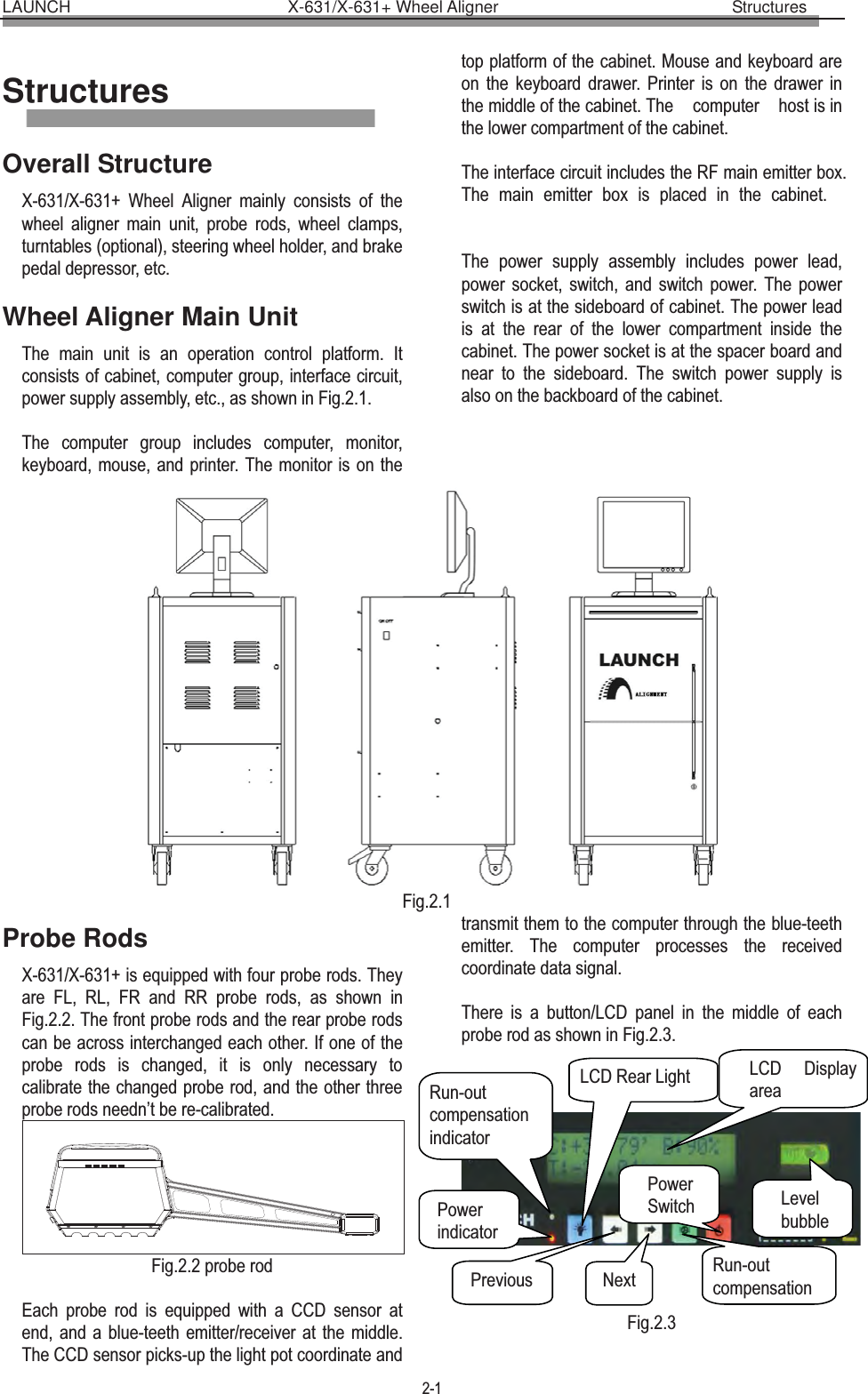
![LAUNCH X-631/X-631+ Wheel Aligner Operation Instructions 4-2 [Navigation column]: To enter into the item you want to test in spite of the default sequence. [Commonly used data list]: The vehicle model in the list can be directly selected to perform the next-step operation. It is blank when firstly used. Only the vehicle model data must be added into this list from the standard database, can the list be used (See [System Management] - [Commonly used data management]). [Selected from standard data]: If there is no the vehicle model you want, you can directly search for the vehicle model you want from the standard database, and directly perform the next-step operation˄This vehicle model is no longer saved in the commonly used data list˅. If you want to add this vehicle model into the commonly used data list, it needs to be added from the interface of [System Management] - [Standard Data Management]). [Quick search]: The input box for quick search aiming at the vehicle model is provided at the bottom of the interface. Please input the first letter of the vehicle model to perform the searching operation. [Tire parameter]: When the unit of toe-in is used in mm or In (The unit of toe-in can be set in [System Management] – [System setting]), the diameter of the present tire must be input. [Low chassis measurement setting]: When test the vehicle with the low chassis, please use this setting to perform the measurement for the intelligent position- dropping of the probe rod's end part, in order to solve the problem of blocking the sensors when testing the vehicle with the low chassis. This setting can be automatically reset when re-selecting the vehicle model or exiting the test system. Caution: After the probe rod's position dropped, the level adjustment should take the electronic level as the standard. [Help]: To provide the description of operating method and note. Operating procedures: Select the corresponding vehicle model item in [Commonly used data list], then click [Next]. Note:1. When the toe of the system uses linear measure, it is required to enter the vehicle tire diameter at the right bottom corner on this interface, otherwise the system cannot enter the next operating procedure 2. The form currently provided is the same form with Commonly Used Data Management in the System Management interface, in the same way, you can click button to add the standard data provided by the system into this form. If you want to add user-defined data, you need to add it from Standard Data Management interface of System Management. The unit of Wheelbase, Front wheelbase and Rear wheelbase is mm. Special Measurement: For different data of vehicle model, some special measurement methods and operating procedures will occur: 1. Aiming at some vehicle model of Benz, the system provides the operations for measuring the standard data with gradient meter. When the data selected is of Benz vehicle, the system will pop up a dialogue box as shown in Fig.4.4. Fig.4.4 The interface for vehicle level measurement is displayed in Fig.4.5. Fig.4.5 Use gradient meter—the special measurement instrument (optional) to get the level values of four wheels, which are displayed in the editing boxes. Also, the operator can take the level value scopes displayed on the top of the editing boxes as the reference, and manually input the corresponding level values of four wheels. [Vehicle Adjustment Help]: It provides the using method of the gradient meter for Benz vehicle, the operator can perform the vehicle test and adjustment with the reference of the operating methods in Help Vehicle adjustment Help](https://usermanual.wiki/Launch-Tech/X631WAPR/User-Guide-1779792-Page-17.png)
![LAUNCH X-631/X-631+ Wheel Aligner Operation Instructions 4-3 interface as shown in Fig.4.6. Fig.4.6 Operating procedures: According to the prompts on the interface of [Vehicle adjustment Help], please perform the level measurement for four suspensions by the way of using the gradient meter, and then connect the gradient meter to the computer host, the system will confirm the standard data of current vehicle model according to each level value measurement by the gradient meter. 2. When some special vehicle models (such as BMW 3 series) are selected, the screen will pop up an interface of [Vehicle Counterweight] as shown in Fig.4.7. Fig.4.7 According to the requirements on the interface, put the sandbags with appropriate weight on the vehicle seats or in the baggage case, and fill the oil tank according to the requirement. Please click [NEXT] button to perform the next operation after finishing the previous procedures. 3. When some special vehicle models (such as BMW 3 series) are selected, the screen will pop up an interface of [Height Measurement] as shown in Fig.4.8. This interface provides an operating platform for ride height measurement system, in order to check if the ride height meets the design requirements of OEM. Fig.4.8 Operating methods: According to the prompts on the picture at the bottom of the interface, measure left, right, front and rear ride height values respectively to see if they are within the standard range or not. If the height measurement value(s) is (are) not within the standard range, please check the vehicle status, and adjust the corresponding components to keep 4 Height Measurement Values within the standard range. Click [NEXT] after finished. 4. When some special vehicle models (such as RENAULT MEGANEĊ) are selected, the screen will pop up an interface of [Dependent Suspension Measurement] as shown in Fig.4.9. This interface provides an operating platform for dependent suspension measurement system, in order to confirm the standard data according to the current status of the vehicle body. Fig.4.9 Operating methods: According to the prompts on the picture at the bottom of the interface, measure left, right, front and rear ride height values respectively, and input them into the corresponding inputting boxes. Click [NEXT] after finished. Caution: 1). Testing conditions for ride height measurement zSpecified tire pressure zGood and even tread pattern zSpecified wheel bearing clearance](https://usermanual.wiki/Launch-Tech/X631WAPR/User-Guide-1779792-Page-18.png)
![LAUNCH X-631/X-631+ Wheel Aligner Operation Instructions 4-4 zSpecified rim and tire zThe brake pedal depressor is installed zCounterweight the whole vehicle according to the normal driving conditions. Adjust the seats to the middle positions and fill the gasoline tank full. 2). If the measured values are beyond the tolerance range, it indicates that the vehicle is faulty, and the faults must be eliminated before performing the ride height measurement. 3). For the vehicle with air shock absorbers, please pull out the security device of the air feeding equipment to prevent the vehicle from being adjusted up and down. 4). The sandbags and height measurement meter are not delivered with the instrument, users should prepare them by themselves. Run-out Compensation This function is to reduce the error caused by the distortion of the wheel rim and tire. It is advisable to select this function to ensure measuring accuracy. The interface is as shown in Fig.4.10. Fig.4.10 [Icon for the level status of probe rod]: To indicate the level status of the present probe rod. Green indicates the probe rod is level and red indicates not level. [Previous]: To return to the previous operating procedure. Operating procedures: 1. Keep the vehicle wheels on straight-ahead positions, fix the steering wheel with the steering wheel holder, remove the brake pedal depressor to keep the wheels can be freely rotated. 2. Install four wheel clamps and probe rods, and then adjust each probe rod level respectively. 3. According to the prompts on the screen, start the run-out compensation operation for LF wheel. Adjust LF probe rod level, and click [NEXT] after finished. 4. According to the prompts on the screen, turn LF wheel by 180°. Adjust LF probe rod level, and click [NEXT] after finished. 5. According to the prompts on the screen, turn LF wheel by 360°. Adjust LF probe rod level, and click [NEXT] after finished. 6. According to the prompts on the screen, perform the run-out compensation operation for RF, RR and LR wheel respectively. 7. Put down the vehicle body, keep the four wheels on the ground. Shake the vehicle body, keep four wheels cling to the ground, the run-out compensation operation is finished (The interface displays the values of run-out compensation). Caution: 1. Before performing run-out compensation operation, be sure to fix the steering wheel according to the requirements, in order to avoid the wheels' swing to left or right when performing run-out compensation operation, causing the inaccurate run-out compensation. 2. You are required to swing the vehicle tires when performing the run-out compensation operation. Keep each probe rod to be at rest comparatively and level (if some probe rod is not level during operating, the system cannot perform the next operation until the probe rod is adjusted level). 3. If the left wheels and right wheels of some vehicles are linked (i.e. when left wheel rotates, the right wheel rotates, too), and you want to perform run-out compensation operation, you must hold the right (left) wheel when you rotate the left (right) wheel, and you should notice that force from you hands must be balanced (in order to avoid wheel's swing to left and right and causing inaccurate run-out compensation). Meanwhile you should check if the probe rods are level or not. If not, it is necessary to adjust the probe rods level by the way of rotating the wheels. You should note that the probe rods mustn't be adjusted level by the way of loosing them. 4. If the second-time lift can put up the front and rear axles at the same time, the front and rear axles should be put up at the same time when performing the run-out compensation operations; if the second-time lift can only put up one axle at a time, please put up the front axle individually when performing the front wheel run-out compensation operations, and put up the rear axle individually when performing the rear wheel run-out compensation operations. 5. Three types of run-out compensation operation modes (90°, 180° and rolling run-out compensation) can be set on the interface of [System Management]-[System Setting]. 180°run-out compensation mode is a standard one. It is with high accuracy, and cross reference between front and rear probe rod is necessary The icon for the level status of probe rod Previous](https://usermanual.wiki/Launch-Tech/X631WAPR/User-Guide-1779792-Page-19.png)
![LAUNCH X-631/X-631+ Wheel Aligner Operation Instructions 4-5 for the measurement under this mode; the accuracy of 90°run-out compensation mode is comparatively lower, but each probe rod can finish run-out compensation operation independently under this mode, needless to take other probe rod as reference. This run-out compensation operation mode can be selected in the case of CCD sensor cannot work normally caused by second-time lift or other factors; it is not required to lift up the vehicle during rolling run-out compensation operation. Only vehicle-pushing is required to accomplish the run-out compensation operation. Among the three kinds of run-out compensation modes mentioned above, the accuracy of rolling run-out compensation is lowest. Vehicle-pushing Run-out Compensation Vehicle-pushing run-out compensation is mainly used for getting the inherent parameters of the four wheels before the normal measurement, so as to ensure the measurement more accurate. You do not always perform this operation. If the measurement is accurate, the user can directly skip this step, and start from Caster Swing measurement. The interface is as shown in Fig.4.11: Fig.4.11 Operating procedures: 1. Turn the steering wheel to make the front wheels on straight-ahead position. Hold the steering wheel with the steering wheel holder, and then remove the brake pedal depressor; 2. Respectively install four wheel clamps and probe rods, and then adjust each probe rod level; 3. Release all four probe rods respectively, and push the vehicle back by 45°, and then adjust all probe rods level. Please click [NEXT] after finished; 4. Push the vehicle back to the original position, and then adjust all probe rods level. Please click [NEXT] after finished. Caster Swing Kingpin measurement is aimed at the front wheels, which includes kingpin inclination and caster. Correct Kingpin Inclination can equalize the loads applied on bearings so that the life of bearings can be prolonged and the controllability of steering is improved. The existence of kingpin inclination can make the intersection point of steering axes and road surface be in front of the adherent point between tire and the ground, which can make use of the resistance from the road surface to the tire to keep the vehicle driven straight-ahead. The interface is as shown in Fig.4.12. Fig.4.12 Operating procedures: 1. Adjust the steering wheel to straight-ahead status, i.e. when the toe-in of FL wheel is equal to the toe-in of RF wheel, the small round ball on the operating interface will move to middle position and turn green from red. At this moment you can adjust all probe rods level. 2. Turn the steering wheel left or right, after arriving at the desired position, the small ball turns green again from red. It indicates that the acquisition for this side is finished. 3. Center the steering wheel, and turn it in reverse direction, after arriving at the desired position, the newly created small ball turns green again from red, and the acquisition is finished. After test finished, please center the steering wheel. The system will automatically return to the next page to check the measurement result. The interface is as shown in Fig.4.13.Fig.4.13 [Measurement for Max. steering angle]: According to the prompts on the screen, read the data of Max. steering anglesindicated by mechanical turntables for FL and HELP for vehicle adjustment Detailed data](https://usermanual.wiki/Launch-Tech/X631WAPR/User-Guide-1779792-Page-20.png)
![LAUNCH X-631/X-631+ Wheel Aligner Operation Instructions 4-6 FR wheels, and input them into the corresponding data boxes respectively, and then click [Return]. The interface is as shown in Fig.4.14. Fig.4.14 [HELP for vehicle adjustment]: Click this button, the screen will pop up an interface of [HELP for vehicle adjustment], the different kingpin adjusting methods for various vehicle models have been enumerated in this interface for vehicle adjustment, the operator can perform the kingpin adjustment operation according to the operating methods in the HELP interface. The interface is as shown in Fig.4.15 Fig.4.15 [Detailed data]: This interface provides the result outputs for whole testing operations, which includes the measured values of each parameter for front and rear wheels. The interface is as shown in Fig.4.16. Fig.4.16[Figure format]: Figure format data display mode is newly added in the system. Click [Word Format] button to switch it between Traditional Data Format and newly-added Figure Format. The interface is as shown in Fig.4.17. Fig.4.17 Caution: 1. Before perform kingpin measurement, please install brake pedal depressor and lock the hand brake first, in order to ensure the vehicle wheels cannot move; remove the steering wheel holder finally. 2. The steering angle for [Kingpin Steering Operation] can be set on the interface of [System Setting]. The standard kingpin measurement is the measurement of 20-degree-steering. But in some special cases, 10-degree-steering measurement can be selected when the steering angle cannot be up to 20 degrees. 3. The measured values are displayed with different colors on each measurement interface. zGreen, it indicates that the measured values are within the standard specifications. zRed, it indicates that the measured values are beyond the standard specifications. zBlue, it indicates that this measured parameter has not the standard specification. Rear axle measurement This interface can provide the real-time result related to rear axle measurement, the operator can compare the measurement result with the reference data while adjusting the vehicle, until the vehicle is adjusted to the best status. The interface is as shown in Fig.4.18. Fig.4.18 Double click HELP for vehicle adjustment Language format Put up the vehicle body](https://usermanual.wiki/Launch-Tech/X631WAPR/User-Guide-1779792-Page-21.png)
![LAUNCH X-631/X-631+ Wheel Aligner Operation Instructions 4-7 [Double click]: Double click (with left key of the mouse) on the data display forms for camber and toe-in of RL and RR wheels, the corresponding displayed data will be enlarged. The interface is as shown in Fig.4.19. Fig.4.19 [Additional Measurement]: This interface provides an operating platform for special measurement, which can measure and display left lateral offset, right lateral offset, axle offset, front setback, rear setback, track width difference and wheelbase difference, etc. The interface is as shown in Fig.4.20. Fig.4.20 Click pushbutton to select the parameters of standard vehicle model. If the parameter values of wheelbase and front/rear track width are contained in the standard database, each angle value displayed on the screen will automatically be converted into length value with the unit of mm. The interface is as shown in Fig.4.21. Fig.4.21 Note: The system provides the dynamic measurement and display for these special values, but the measurement result will not be saved in the database. [HELP for vehicle adjustment]: Click this button, the screen will pop up an interface of [HELP for vehicle adjustment], the different toe-in and camber adjusting methods for various vehicle models have been enumerated in this interface for vehicle adjustment, the operator can perform the toe-in and camber adjustment operation according to the operating methods in the HELP interface. The interface is as shown in Fig.4.22. Fig.4.22 [Lift up the vehicle body]: Sometimes it is required to lift the vehicle body up in order to be convenient to adjust front/rear camber and caster. When the vehicle wheels are lifted up, the inclinometers will move, and the corresponding measured values will change, too. In this case, please use Lifting Adjustment function. Click button, and then lift up the vehicle body according to the prompts on the screen. The software will automatically compensate the offset of inclinometer in order to realize accurate adjustment.](https://usermanual.wiki/Launch-Tech/X631WAPR/User-Guide-1779792-Page-22.png)
![LAUNCH X-631/X-631+ Wheel Aligner Operation Instructions 4-8 Fig.4.23 Attention: After adjustment, please remember to click button, and then put down the vehicle body according to the prompts on the screen. If the lift is not put down, it will be limited to select the other interfaces (except for [Front axle measurement] interface) as shown in Fig.4.24. Fig.4.24 Front axle measurement This interface can provide the real-time result related to front axle measurement, the operator can compare the measurement result with the reference data while adjusting the vehicle, until the vehicle is adjusted to the best status. The interface is as shown in Fig.4.25. Fig.4.25 [Double click]: Double click (with left key of the mouse) on the data display forms for camber and toe-in of LR and RR wheels, the corresponding displayed data will be enlarged. [Additional measurement]: This interface provides an operating platform for special measurement, which can measure and display left lateral offset, right lateral offset, axle offset, front setback, rear setback, track width difference and wheelbase difference, etc. [Toe-in adjustment for the front wheel steering]: Click to perform toe-in adjustment for front wheel steering, and click to center the steering wheel (Note: When using two probe rods to perform the measurement operation, only total toe-in is displayed, and individual toe-in is not displayed). [HELP for vehicle adjustment]: Click this button, the screen will pop up an interface of [HELP for vehicle adjustment], the different adjusting methods for various vehicle models have been enumerated in this interface for vehicle adjustment, the operator can perform the vehicle adjustment operation according to the operating methods in the HELP interface. [Lift up vehicle body]: Sometimes it is required to lift the vehicle body up in order to be convenient to adjust front/rear camber and caster. When the vehicle wheels are lifted up, the inclinometers will move, and the corresponding measured values will change, too. In this case, please use Lifting Adjustment function. Click button, and then lift up the vehicle body according to the prompts on the screen. The software will automatically compensate the offset of inclinometer in order to realize accurate adjustment. Attention: After adjustment, please remember to click button, and then put down the vehicle body according to the prompts on the screen [Toe-in curve change] provides the special measurement methods relative to some vehicle models of VOLKSWAGE and AUDI, etc. First, the operator must adjust the toe-in curve changes of these kinds of vehicles to the standard range, and then Front Axle Measurement can be performed normally. When [Toe-in Curve Change] is activated, please click the icon of , the screen will display the interface as shown in Fig.4.26. Double click HELP for vehicle adjustment Lift up vehicle body Additional measurement Toe-in curve change](https://usermanual.wiki/Launch-Tech/X631WAPR/User-Guide-1779792-Page-23.png)
![LAUNCH X-631/X-631+ Wheel Aligner Operation Instructions 4-9 Fig.4.26 Operating Methods: 1. Click [Toe-in Curve Change] on the interface of [Front Axle Measurement] to enter Toe-in Curve Change interface as shown in Fig.4.24. 2. According to the prompts on the screen, please select the appropriate vehicle adjustment tools by the way of referring to the vehicle adjustment HELP information for the front toe-in curve change regulator. Please perform the next operation procedure after finished. 3. The vehicle is now in put-down status (position B1). Adjust the vehicle front toe-in to the allowed scope according to the standard specifications (see Fig.4.25). Put up the vehicle with the special tools equipped according to the prompts on the screen. Click [NEXT] button, the screen will display the interface as shown in Fig.4.27. Fig.4.27 4. Put up the vehicle (to position B2) according to the requirements of the manufacturer. The screen display the interface as shown in Fig.4.28: Fig.4.28 5. Put down the vehicle to position B1. Adjust the vehicle front toe-in to the allowed scope according to the standard specifications. The interface is as shown in Fig.4.29: Fig.4.29 6. Put down the vehicle, and then click button to return to the interface of [Front Axle Measurement]. Attention: After adjustment, please remember to click button, and then put down the vehicle body according to the prompts on the screen. If the lift is not put down, it will be limited to select the other interfaces (except for [Rear axle measurement] interface) as shown in Fig.4.30. Fig.4.30 Print Report Print Report can print and save the alignment data of the vehicle under test. The interface is as shown in Fig.4.31.](https://usermanual.wiki/Launch-Tech/X631WAPR/User-Guide-1779792-Page-24.png)
![LAUNCH X-631/X-631+ Wheel Aligner Operation Instructions 4-10 Fig.4.31 [Vehicle license plate number]: The license plate number of the vehicle under test. [Client information]: The corresponding information for the owner of the vehicle under test, including [Client name], [Contact], [Telephone] and [Address]. The client information cannot be directly entered in this interface with the keyboard. Icon behind [Client name] must be clicked to enter the interface of [Client Management], and then the corresponding [Client information] can be selected. If information of this client is not available in [Client Management], it must be added first before selection (Please refer to [Configuration] – [Client management]). [Vehicle information]: The corresponding information of the vehicle under test, including [Mileage], [Manufacturer], [Model], [Start year] and [End year]. The vehicle information cannot be directly entered in this interface with the keyboard. If the vehicle model has been selected in [Measurement] – [Select vehicle model], the corresponding information of the vehicle model selected will be displayed in this interface. If not, no any information is displayed in this interface. [Operator]: Name of the operator who is operating the instrument now. The corresponding [Operator] can be selected only after the [Operator] column of [Information for service station] is added (Please refer to [System management] – [User information]). [Fault cause]: The symptoms of the vehicle under test. There are 5 options: [Tire wear], [Pull], [Steering wheel is not centered], [Steering wheel swings] and [Others]. [Save]: To save the alignment data of the vehicle under test ([Vehicle plate number] and [Client name] must be entered, and [Fault cause] must be selected first before saving). [Print]: To print the alignment data of the vehicle under test in the format of form or image (Please refer to [System management] – [Report setting] for the format setting of the report form). Caution: The report form print function provided by this interface only aims at the individual information report form for the test at this time; the report form print function provided by the main interface aims at all the information report forms saved and done before. Quick Measurement Select [Quick measurement] icon on the main menu, the system will enter the [Quick measurement] interface. This interface provides an operating platform for quick measurement, which can test and display toe-in and camber of front and rear wheels at the same time. The interface is as shown in the following figure: Fig.4.32 [Select Vehicle Model]: You can select the parameters of standard vehicle models to be convenient for vehicle adjustment (Please refer to [Standard Measurement]-[Select Vehicle Model]); [Print Report]: To provide the functions for saving and printing the test data (Please refer to [Standard Measurement]-[Print Report]). [Figure Format]: It is the data display interface which can be switched to Figure Format. The fig-format data display interface provides the display for thrust angle. The interface is as shown in Fig.4.33. Fig.4.33 Note: Print Save Vehicle license plate number Client information Fault cause Select Vehicle Model Figure format Print report](https://usermanual.wiki/Launch-Tech/X631WAPR/User-Guide-1779792-Page-25.png)
![LAUNCH X-631/X-631+ Wheel Aligner Operation Instructions 4-11 1. This interface provides only the functions of the test and adjustment for front and rear toe-in and camber. For other functions, please select them on the interface of [Standard Measurement]. 2. The default unit for toe-in on this interface is centigrade. Only the vehicle model data is selected, can the display unit for toe-in be in accordance with the toe-in unit set on the interface of System Management]-[System Setting]. 3. Only the vehicle model data is selected, can the measured values be saved in the interface of [Print Report]. Special Note: During [Caster Swing], [Rear Axle Measurement], [Front Axle Measurement] and [Quick Measurement], if the sensor is blocked, it is necessary to perform the settings for low-chassis vehicle. The interface is as shown in Fig.4.34. 4.34 This setting can be automatically reset when re-selecting the vehicle model or exiting the test system. Caution: After the probe rod's position dropped, the level adjustment should take the electronic level as the standard. Additional Measurement This interface provides an operating platform for special measurement, which can measure and display left lateral offset, right lateral offset, axle offset, front setback, rear setback, track width difference and wheelbase difference, etc. The interface is as shown in Fig.4.35. Fig.4.35 [Select Vehicle Model]: Click this button to select the parameters of standard vehicle model. If the parameter values of wheelbase and front/rear track width are contained in the standard database, each angle value displayed on the screen will automatically be converted into length value with the unit of mm. Caution: The system provides the dynamic measurement and display for these special values, but the measurement result will not be saved in the database. System Measurement On the main menu, please click the icon of [System Measurement] to enter the measurement interface as shown in Fig.4.36. Fig.4.36 User information <>The information of maintenance station is mainly used to record the contact method of the maintenance station and the information of the maintenance technician. This kind of information can be imported to report forms, which can make the information of maintenance station be displayed on the report form printed out, and is convenient for your data management and tracing operation. The interface is as shown in Fig.4.37. Fig.4.37 [Setting]: After entering this interface, the information box will be displayed with French gray back-ground, in Select Vehicle Model](https://usermanual.wiki/Launch-Tech/X631WAPR/User-Guide-1779792-Page-26.png)
![LAUNCH X-631/X-631+ Wheel Aligner Operation Instructions 4-12 this state the system only provides view function. Click button to perform information editing operation. After entering the information, please click button, the system will automatically save the information and return to the previous interface. Note: If there are multi-operators for performing wheel alignment, the input method of recording or saving the operators' names is using "#" to separate every operator's name. For instance, Tom#John#Paul#Steven#. Client management: Client information is very important in our daily routine, so we must manage and maintain these data very well, which can ensure us to solve the problem in time and improve our service quality. The interface is as shown in Fig.4.38. Fig.4.38[Quick search]: Directly input the first letter of the customer name in the text box, the system will automatically perform the search operation. [Add]: Click this button, and then add the client information in the pop-up window for detailed information of the client. The interface is as shown in Fig.4.39. Fig.4.39 [Modify]: Select the items required to modify, and then click this button, modifying the client information in the popped-up window for the detailed information of client. [Delete]: Delete the items selected in client information data form. When performing Delete operation, please note that Delete operation will delete all the corresponding information (including previous testing information) of client. Ensure that you do want to delete the information before performing Delete operation. [Print]: Print client information data form. The input box for Quick search aiming at the vehicle model provided at the bottom of the interface OEM Specs This interface provides the parameter information (These parameter information has been set before the vehicles leave factory) for the vehicles with various models. The database contains the information of various kinds of vehicles manufactured by many manufacturers all over the world, and the contents in database can be updated in time via system upgrade. In addition, this interface provides the function of adding the user-defined data. The operator can add by him-self (or her-self) all the vehicle model information which the standard database does not has. This system is fit more for the service data application. The interface is as shown in Fig.4.40. Fig.4.40 [Search for model]: To provide the function of Quick search for vehicle model. Directly input the first letter of the model name of the vehicle under test in the text box, the system will automatically perform the search operation. [Newly added]: To add the vehicle models which are not included in the standard database. Click this button, you can add the user-defined information in the popped-up window (as shown in the following figure) for the detailed information of the user-defined data. After confirming, you can save the information into the data list. Quick search for model Delete Modify Newly added](https://usermanual.wiki/Launch-Tech/X631WAPR/User-Guide-1779792-Page-27.png)
![LAUNCH X-631/X-631+ Wheel Aligner Operation Instructions 4-13 Fig.4.41 [Modify]: This function is only applied to modifying the user-defined information in the list. It cannot modify the information imported from the standard data. [Delete]: This function is only applied to deleting the user-defined information in the list. It cannot delete the information imported from the standard data. Operating procedures: Directly click manufacturer to select corresponding vehicle model, in order to give the operator a convenient view for the standard data of the vehicle model. Frequent Model In order to speed up the information search, the system provides the commonly used data management function which can individually add the vehicle information in the standard data into the commonly used data. The interface is as shown in Fig.4.42. Fig.4.42 [Added from the standard data]: Click this button, the standard data window will be activated. Select the required vehicle model from the standard data list. After confirming, the information can be added from the standard data to the commonly used data list. [Delete]: Delete the items selected from the commonly used data. System Setting System setting function is used to adjust the function and display effect of software system. The interface is as shown in Fig.4.43. Fig.4.43 [Basic setting]: With this function the system can be switched between Normal Version and Demo Version, and between Special Version and Common Version. [Normal version]: is the version directly applied in actual testing operation; [Demo version]: this version can, in stand-alone status, simulate the testing process without external hardware equipments, it hasn't testing ability, only used to demonstrate the testing process; [Common version]: this version provides all-around HELP information and operating demo animation to fully help the testing personnel who contacts this system for the first time; [Special version]: for experienced operator, too much HELP information will, on the contrary, become encumbrance, so this version provides the necessary HELP information only to make the operator be working with more high efficiency. [Normal mode]: It is a default mode, and used in the case of no direct sunlight or strong ground reflection light. [Strong light mode]: It is used when there is direct sunlight or strong ground reflection light. [Setting for run-out compensation]: the system provides three types of run-out compensation: 1) 180-degree compensation (turning for 2 times) 2) 90-degree compensation (turning for 4 times) 3) Rolling run-out compensation. [Setting for kingpin steering operation]: the system provides two types of kingpin measurement: 1) Steering wheel turns by 20 degrees; 2) Steering wheel turns by 10 degrees. [Probe rod calibration setting]: you can select all CCD sensors or end CCD sensor to calibrate [Probe rod setting]: When one pair of front probe rods or rear probe rods is faulty, you can use the normal pair of probe rods to finish the part of the test items. For example, all four probe rods are used in normal case. When front probe rods are faulty, you can select “Use rear probe rods” to tell the system only to use rear probe rods to perform the test. Delete Added from the standard data](https://usermanual.wiki/Launch-Tech/X631WAPR/User-Guide-1779792-Page-28.png)
![LAUNCH X-631/X-631+ Wheel Aligner Operation Instructions 4-14 [Unit setting]: Used to set the displayed unit system of system data, two types of unit systems can be selected: percentage degree system and degree/minute system. [Unit setting for toe-in]: Aiming to the particularity of the unit for toe-in, the system adds the units of mm and inch. Note:If you want to use long measure as the unit of toe-in, during performing standard measurement, the system will require the operator to enter the diameter of the tires when entering the operating interface of Select Vehicle Model. Report setting Report setting can set the format type of the report form. The interface is as shown in Fig.4.44. Fig.4.44 [Report form 1]: Format 1 is for detailed report form, which includes the items of Before Adjustment, After Adjustment, Standard maximum and minimum values. [Report form 2]: Format 2 is for concise report form, which lists the data information before and after adjustment only. [Report form 3]: Format 3 is for fig report form. The interface is as shown in Fig.4.45. Fig.4.45 Select Language The system has provided many languages to select. The interface is as shown in Fig.4.46 Fig.4.46 Operating procedures: Select your desired language, and then click button, the system will restart and switch to the interface with the language you selected. Probe Rod Maintenance This function has provided six operations. Detailed information of probe rod: Used to view the running status of sensor inside the probe rod. Status of probe rod: Used to view the status of communication and electricity quantity of probe rod. Self-test for measurement accuracy of probe rod: Used for testing whether toe-in and camber values measured by the probe rod currently used are correct or not, and tell client or after-sales service personnel if the probe rod needs to be recalibrated. Probe rod update: Mainly used for probe rod update service performed by after-sales service personnel. Electronic level correction for probe rode: Mainly used for solving the problem of the disaccord between electronic level and mechanical level due to long-time use of the probe rod. Calibration for probe rod: Used to reset the calibration value of probe rod. The interface is as shown in Fig.4.47.](https://usermanual.wiki/Launch-Tech/X631WAPR/User-Guide-1779792-Page-29.png)
![LAUNCH X-631/X-631+ Wheel Aligner Operation Instructions 4-15 Fig.4.47 Detailed Information of Probe Rod: In the [Probe rod maintenance] interface, click the icon to enter the interface for the detailed information of probe rod. This interface can directly display the running status of 8 CCD sensors and 8 clinometers inside the 4 probe rods. The interface is as shown in Fig.4.48. Fig.4.48 [Select probe rode]: One of the probe rods will be displayed bright green after clicking the icon of this probe rod. [CCD status]: To display the coordinate and using status of the 2 CCD sensors inside the probe rod selected. [Inclinometer status]: To display the coordinate and using status of the 2 inclinometers inside the probe rod selected. Operating procedures: Directly click the probe rod you want to check in the model figure at left side, the probe rod you have selected will be highlighted, the current readings of the four probe rods can be displayed in reading scale figure at right side. If certain sensor cannot read data, it indicates that this probe rod has been abnormal. Status of probe rod: In the [Probe rod maintenance] interface, click the icon to enter the interface of the probe status. Status of probe rod is used to display the communication status between probe rod and system. The interface is as shown in Fig.4.49. Fig.4.49 When communication between probe rod and system is normal, will be displayed on probe rod, otherwise will be displayed to indicate the faulty communication. Also the current status of electricity quantity in probe rod can be displayed in the case of the communication between the probe rod and system is normal, respectively two kinds of status are as follows: 1. Full electricity 2. Low electricity Self-test for the Measurement Accuracy of Probe Rod In the interface of [Probe Rod Maintenance], please click the icon of [Self-test for Measurement Accuracy of Probe Rod], the system will enter the interface as shown in Fig.4.50. The probe rod measurement accuracy self-test function is used for testing whether toe-in and camber values measured by the probe rod currently used are correct or not, and tell client or after-sales service personnel if the probe rod needs to be recalibrated. Fig.4.50 Select probe CCD status linclinometer status](https://usermanual.wiki/Launch-Tech/X631WAPR/User-Guide-1779792-Page-30.png)
![LAUNCH X-631/X-631+ Wheel Aligner Operation Instructions 4-16 According to the prompts on the screen, install 4 probe rods on the wheels respectively, and then adjust them level. Click [NEXT] after finished. Fig.4.51 The screen will prompt whether the toe-in measurement accuracy of 4 probe rods is normal or not. If not, it is required to recalibrate. Fig.4.52 According to the prompts on the screen, take FL wheel as reference, install FL probe rod on FL wheel, and then adjust the probe rod level. Click [NEXT] after finished. Fig.4.53 Remove FL probe rod, install FR probe rod on FL wheel, and then adjust the probe rod level. Click [NEXT] after finished. Fig.4.54 Remove FR probe rod, install LR probe rod on FL wheel, and then adjust the probe rod level. Click [NEXT] after finished. Fig.4.55 Remove RL probe rod, install RR probe rod on FL wheel, and then adjust the probe rod level. Click [NEXT] after finished. Fig.4.56 The screen will prompt whether the camber measurement accuracy of 4 probe rods is normal or not. If not, it is required to recalibrate. Caution: This function does not need calibration frame, it can be performed on any one of vehicles. Probe Rod Update In the interface of [Probe Rod Maintenance], please](https://usermanual.wiki/Launch-Tech/X631WAPR/User-Guide-1779792-Page-31.png)
![LAUNCH X-631/X-631+ Wheel Aligner Operation Instructions 4-17 click the icon of [Probe Rod Update], the screen will pop up a password inputting box as shown in Fig.4.57. Fig.4.57 Enter the password (provided by Launch), and then click [OK] button to enter the interface of Probe Rod Update as shown in Fig.4.58. Fig.4.58 Directly click the icon of the probe rod required to update, the probe rod icon selected will be highlighted. Click button ˈthe screen will prompt the operator to press, at the same time within the limited period, the key combination of [Previous]+[Next] on the control panel of the probe rod required to update, in order to trigger the probe rod to accomplish the update operation. The screen will prompt whether the probe rod update is successful or not. Caution: The information such as calibration values, recognition number, etc. of each probe rod is all stored inside the memory of the probe rod itself. When replacing or recalibrating the probe rod, it is required to use this function to read the information stored inside the probe rod and save it inside the computer host, in order to realize the match between the probe rod and the computer host. Electronic Level Correction for Probe Rod In the interface of [Probe Rod Maintenance], please click the icon of [Electronic Level Correction for Probe Rod], the screen will pop up a password inputting dialog box. Enter the password (provided by Launch), and then click [OK] button to enter the interface of Electronic Level Correction for Probe Rod. The function of probe rod electronic level correction is mainly used for solving the problem of the disaccord between electronic level and mechanical level due to long-time use of the probe rod. The interface is as shown in Fig.4.59. Fig.4.59 According to the prompts on the screen, adjust the level bubble to the middle position. Click [OK] button after finished. The screen will prompt whether electronic level correction for the probe rod is successful or not. Caution: Before performing the operation of electronic level correction for probe rod, it must be ensured that the communication of 4 probe rods is normal. Calibration for Probe Rode In the [Probe rod maintenance] interface, click the icon , the screen will pop up a password inputting dialogue box. Enter password, and then click [OK] button, the screen will display the interface as shown in Fig.4.60. Fig.4.60 Click [NEXT] button, the interface is as shown in Fig.4.61.](https://usermanual.wiki/Launch-Tech/X631WAPR/User-Guide-1779792-Page-32.png)
![LAUNCH X-631/X-631+ Wheel Aligner Operation Instructions 4-18 Fig.4.61 According to the prompts on the screen, adjust the calibration bracket level, and then click [NEXT] button. The interface is as shown in Fig.4.62. Fig.4.62 According to the prompts on the screen, install 4 probe rods and adjust them level, switch off the power supplies FL and RL probe rods, switch on the power supplies of FR and RR probe rods, and then click [NEXT] button. The interface is as shown in Fig.4.63. Fig.4.63 According to the prompts on the screen, please click [NEXT] button to sample data. The interface is as shown in Fig.4.64. Fig.4.64 According to the prompts on the screen, switch on the power supplies of FL and RL probe rods, and switch off the power supplies of FR and RR probe rods, and then click [NEXT] button. The interface is as shown in Fig.4.65. Fig.4.65 According to the prompts on the screen, please click [NEXT] button to sample data. The interface is as shown in Fig.4.66. 4.66 According to the prompts on the screen, turn the calibration frame shaft by 180 degrees, install all probe rods and adjust them level; switch off the power supplies of FL and RL probe rods, and then click [NEXT]. The interface is as shown in Fig.4.67.](https://usermanual.wiki/Launch-Tech/X631WAPR/User-Guide-1779792-Page-33.png)
![LAUNCH X-631/X-631+ Wheel Aligner Operation Instructions 4-19 Fig.4.67 According to the prompts on the screen, please click [NEXT] button to sample data. The interface is as shown in Fig.4.68. Fig.4.68 According to the prompts on the screen, switch on the power supplies of FL and RL probe rods, and switch off the power supplies of FR and RR probe rods, and then click [NEXT] button. The interface is as shown in Fig.4.69. 4.69 According to the prompts on the screen, please click [NEXT] button to sample data. The interface is as shown in Fig.4.70. 4.70 According to the prompts on the screen, install 4 probe rods and adjust them level, switch on all power supplies of probe rods, and then click [NEXT] button. The interface is as shown in Fig.4.71. Fig.4.71 According to the prompts on the screen, please click [NEXT] button to sample data. The interface is as shown in Fig.4.72. Fig.4.72 According to the prompts on the screen, exchange the probe rods of left side with that of right side and adjust all probe rods level. Switch on all power supplies of the probe rods, and then click [NEXT] button. The interface is as shown in Fig.4.73.](https://usermanual.wiki/Launch-Tech/X631WAPR/User-Guide-1779792-Page-34.png)
![LAUNCH X-631/X-631+ Wheel Aligner Operation Instructions 4-20 Fig.4.73 According to the prompts on the screen, please click [NEXT] button to sample data. The interface is as shown in Fig.4.74. Fig.4.74 According to the prompts on the screen, install FL and FR probe rods and adjust them level. Switch on the power supplies of the probe rods, and then click [NEXT] button. The interface is as shown in Fig.4.75. Fig.4.75 According to the prompts on the screen, please click [NEXT] button to sample data. The interface is as shown in Fig.4.76. Fig.4.76 According to the prompts on the screen, turn the calibration frame shaft by 180 degrees, install FL and FR probe rods and adjust them level; switch on the power supplies of the probe rods, and then click [NEXT]. The interface is as shown in Fig.4.77. Fig.4.77 According to the prompts on the screen, please click [NEXT] button to sample data. The interface is as shown in Fig.4.78. Fig.4.78 According to the prompts on the screen, install RL and RR probe rods and adjust them level; switch on the power supplies of the probe rods, and then click [NEXT]. The interface is as shown in Fig.4.79.](https://usermanual.wiki/Launch-Tech/X631WAPR/User-Guide-1779792-Page-35.png)
![LAUNCH X-631/X-631+ Wheel Aligner Operation Instructions 4-21 Fig.4.79 According to the prompts on the screen, please click [NEXT] button to sample data. The interface is as shown in Fig.4.80. Fig.4.80 According to the prompts on the screen, turn the calibration frame shaft by 180 degrees, install RL and RR probe rods and adjust them level; switch on the power supplies of the probe rods, and then click [NEXT]. The interface is as shown in Fig.4.81. Fig.4.81 According to the prompts on the screen, please click [NEXT] button to sample data. The interface is as shown in Fig.4.82. Fig.4.82 Click [OK] button to display the calibration value changes. The interface is as shown in Fig.4.83. Fig.4.83 Click [OK] button to finish whole calibration procedures. (Caution: If only all calibrated values are not equal to zero, it indicates that the calibration is successful this time; If the calibrated value of any one of ˟˟ˠ and inclinometer is equal to zero, it indicates that the calibration is not successful this time, and it is required to recalibrate. Many factors can result in unsuccessful probe rod calibration, but it is mainly caused by inappropriate calibration operation or hardware fault.) Note:The equipment must be calibrated before leaving factory, in order to make the default parameter inside the probe rod be set to standard value. Generally speaking, the calibration operation for probe rod can be performed in the following three cases: 1. The calibration operation for probe rod can be performed after the equipment has been used for one or more than one year. 2. The calibration operation for probe rod can be performed in the case of the equipment has been impacted ever and the test readings are not up to the standard. 3. The calibration operation for probe rod can be performed in the case of the sensor was faulty and](https://usermanual.wiki/Launch-Tech/X631WAPR/User-Guide-1779792-Page-36.png)
![LAUNCH X-631/X-631+ Wheel Aligner Operation Instructions 4-22 the sensor replacement operation has been performed ever. Data backup and restore The function is used in system data backup application, so as to prevent the WINDOWS system from abnormity caused by external factors (such as virus), and help you to avoid unnecessary loss. The backup function we provide is mainly used to backup the contents of three parts: user and business data information, system configuration file and probe calibration information. The interface is as shown in Fig.4.84. Fig.4.84 Operating procedures: 1. Backup: Click button, find the position of the file you expect to save in pop-up dialogue box (The interface is as shown in Fig.4.82) or enter the path address directly in the blank of exported file path, and then click button finally. Fig.4.85 2. Restore: The similar operation can be performed when the backed-up data need to be imported into the system. Click button, find the position of the file you expect to import in popped-up window or enter the path address directly in the blank of imported file path, then click button, the system will automatically import this back-up file. Log Review Log is the important recorded information for the system running. We can check the system conditions by viewing the log, so we can say that the log is an important window for us to monitor and diagnose the system. During running and testing operation, the system will record some main operations or signals, in this way the information records in log file are built. The interface is as shown in Fig.4.86. Fig.4.86 Operating procedures: [Log column]: To shown the abnormal conditions of the equipment usage in each year. [Save]: When there are records in the log file of system, the required records can be saved by clicking button, and viewed by technical personnel, checking the running conditions of equipment. [Print]: The system has provided the printing function which is convenient to view. Note: Besides the client information needs backup operation regularly, we recommend that the log records need back-up operation regularly, too, so as to be convenient to repair and maintain the equipment. PrintIn main interface, click the icon of [Print] to enter the interface of repot form print. It is mainly used to check or print the normal testing records of the client. The interface is as shown in Fig.4.87. Fig.4.87 Select path Start to backup Start to restore Log column Save Print Print Client list Record list](https://usermanual.wiki/Launch-Tech/X631WAPR/User-Guide-1779792-Page-37.png)
![LAUNCH X-631/X-631+ Wheel Aligner Operation Instructions 4-23 [Client list]: To list the all clients who have been serviced by the alignment test. [Record list]: This list can display the alignment test records (for one time or many times) of the client selected from [Client list]. [Print]: To print the alignment data of the vehicle under test with form or figure format (Please refer to [System Management] – [Report Setting] for the format setting of report form). 3D Interface / 2D Interface 3D Interface is as shown in Fig.4.88. Fig.4.88 2D Interface is as shown in Fig.4.89. Fig.4.89 HelpHELP system provides more detailed operating descriptions. The interface is as shown in Fig.4.90. Fig.4.90 ExitEXIT system has two kinds of prompts: Exit from the system and return to WINDOWS operating interface or Exit and shutdown (Please refer to [System Management] – [System Setting] for the detailed settings). The interface is as shown in Fig.4.91. Fig.4.91 New Functions of X-631+ Wheel Aligner Added Functions for X-631+ Wheel Aligner No PC Mode and the corresponding functions are added. That is to say, without the help of computer, you can perform the corresponding operations on the probe rods in order to realize the basic functions of wheel alignment. Now, you can get the data of camber and toe-in under this No PC Mode. The computer (main unit) is of the master control equipment of the former wheel aligner, and the calculation and display, etc. are all performed on the main unit. Working mode with computer: In this mode, you can perform the wheel alignment operation with the control of the computer. X-631 wheel aligner uses this working mode. No computer working mode (No PC Mode): In this mode, you can use the probe rods to perform the wheel alignment operation without the help of the computer. X-631+ wheel aligner is added with this function. X-631+ wheel aligner No PC Mode has 4 kinds as follows:](https://usermanual.wiki/Launch-Tech/X631WAPR/User-Guide-1779792-Page-38.png)
![LAUNCH X-631/X-631+ Wheel Aligner Operation Instructions 4-24 1. Four-probe rode normal light mode (Normal light-4); 2. Four-probe rod high light mode (High light-4); 3. Two-probe rod normal light mode (Normal light-2); 4. Two-probe rod high light mode (High light-2). These four kinds of mode are same with that on the computer. The start-up interfaces of the probe rods are different: Fig.4.92 The main working interfaces are different: Fig.4.93 Operation Instructions for X-631+ Wheel Aligner First, please enter into No PC Mode of X-631+ wheel aligner. After the probe rods entering the main working interfaces, please press down the keys of [Back Light] and [Run-out Compensation] at the same time, you can enter the selection interface of No PC Mode. There are four kinds of working modes for selection. Press key [Previous] or key [Next] to select the desired mode among these four modes. The mode pointed by the arrow head is the mode selected currently. After selecting working mode, please press down key [Previous] and [Next] at the same time to enter No PC Mode. Fig.4.94 The above interface is the No PC Mode selection interface. Move arrow head to point to the desired item. After selecting working mode, please press down key [Previous] and [Next] at the same time to enter the prompt interface for four-probe rod working mode of No PC Mode. Fig.4.95 Fig.4.96 After selecting working mode, please press down key [Previous] and [Next] at the same time to enter No PC Mode (Two-probe rod working mode). Fig.4.97 On main probe rod, please press key [Back Light] and key [Run-out Compensation] at the same time to exit No PC Mode. The screen will display Exit NO PC Mode. Fig.4.98 Some Explanations about No PC Mode of X-631+ Wheel Aligner 1. The probe rod via which the system enters No PC Mode is of the main probe rod. The main probe rod can perform the control functions (just like main unit) under No PC Mode. 2. One set of probe rods has one main probe rod only. 3. The label of the main probe rod is included with square brackets ([ ]). For example, [FL]: It indicates that FL is of the current main probe rod. 4. If this set of probe rods has had the main probe rod, the other probe rod cannot be set as the main probe rod once more. If you force to do it, the error prompts will be displayed. Fig.4.99 Error prompts: Setting failed! [XX] is Main bar. 5. After entering main working interface, the camber data will usually be displayed. Only after entering No PC Mode can the toe-in data be displayed. The toe-in data will become invalid after the system exits No PC Mode. Battery electricity Qty. Probe rod label Toe-in Camber](https://usermanual.wiki/Launch-Tech/X631WAPR/User-Guide-1779792-Page-39.png)