Launch Tech X631WAPR X-631+Probe User Manual
Launch Tech Co., Ltd. X-631+Probe
User Manual


LAUNCH X-631/X-631+ Wheel Aligner
i
Trademark Information
LAUNCH is a registered trademark of LAUNCH
TECH. CO., LTD. (short for LAUNCH) in China and
other countries. All other LAUNCH trademarks,
service marks, domain names, logos, and company
names referred to in this manual are either
trademarks, registered trademarks, service marks,
domain names, logos, company names of or are
otherwise the property of LAUNCH or its affiliates. In
countries where any of the LAUNCH trademarks,
service marks, domain names, logos and company
names are not registered, LAUNCH claims other
rights associated with unregistered trademarks,
service marks, domain names, logos, and company
names. Other products or company names referred to
in this manual may be trademarks of their respective
owners. You may not use any trademarks, service
marks, domain names, logos, or company names of
LAUNCH or any third party without permission from
the owner of the applicable trademarks, service
marks, domain names, logos, or company names.
You may contact LAUNCH by visiting Launch at
http://www.cnlaunch.com, or writing to Launch
Industrial Park, North of Wuhe Rd., Banxuegang,
Longgang, Shenzhen, Guangdong, P. R. China, to
request written permission to use Materials on this
manual for purposes or for all other questions relating
to this manual.
Copyright Information
Copyright © 2010 by Launch Tech Co., Ltd. All rights
reserved. No part of this publication may be
reproduced, stored in a retrieval system, or
transmitted in any form or by any means, electronic,
mechanical, photocopying, recording or otherwise,
without the prior written permission of LAUNCH. The
information contained herein is designed only for the
use of this unit. LAUNCH is not responsible for any
use of this information as applied to other units.
Neither LAUNCH nor its affiliates shall be liable to the
purchaser of this unit or third parties for damages,
losses, costs, or expenses incurred by purchaser or
third parties as a result of: accident, misuse, or abuse
of this unit, or unauthorized modifications, repairs, or
alterations to this unit, or failure to strictly comply with
LAUNCH operating and maintenance instructions.
LAUNCH shall not be liable for any damages or
problems arising from the use of any options or any
consumable products other than those designated as
Original LAUNCH Products or LAUNCH Approved
Products by LAUNCH.
General Notice
Other product names used herein are for
identification purposes only and may be trademarks
of their respective owners. LAUNCH disclaims any
and all rights in those marks.
LAUNCH X-631/X-631+ Wheel Aligner
ii
Precautions
zPlease read the User’s Manual and the
Installation and Parts Manual carefully before
operating X-631/X-631+.
zOnly the qualified technician can operate the
Wheel Aligner.
zThe operator must have knowledge of computer
application and basic theory of wheel alignment.
zThe power voltage of X-631/X-631+ is
AC230V±10% 50±1Hz / AC110V±10% 60±1Hz
˄AC220V±10% 60±1Hz for South Korea. It can
be customized according to the requirements of
customer˅. The power outlet must be a 3PIN
socket and its earth pin must be well
grounded. Otherwise, the equipment will be
damaged! If the power voltage is not stable,
please purchase and use AC voltage stabilizer.
zX-631/X-631+ is operated with image sensing. Do
not stop the light beam between sensors. Avoid
reflection light of the ground and direct light to the
probe rod while testing.
zCharge the probe rod for 4 hours if it is not
operated for over 30 days. Turn off the power of
the probe rod before charging it.
zThe probe rods are precision parts of the wheel
aligner. Do not plug or unplug the connecting
cable when the power is turned on. Otherwise,
the built-in sensor may be damaged. Special care
should be taken during installation and operation
to prevent the casing from being distorted and
the internal parts from being damaged.
zInstall the lift according to specifications before
installing X-631/X-631+, for it is necessary to lift
the vehicle when adjusting vehicle wheels. The
vehicle may need lift for two times for
compensation of rim run-out. Check the lift
regularly for fixedness and levelness to ensure
personal safety and correct measurement.
Remove the obstacles around the lift for
convenient operation.
zDon’t place X-631/X-631+ on a vibrated object or
an oblique surface. Avoid direct sunlight and
moisture.
zAvoid splashing water on the surface of
X-631/X-631+, for it may cause permanent
damage to the system.
zThe wires inside the cabinet and the probe rod
sensors are connected compactly. Any
disconnection may cause damage to the sensor.
Damage due to unauthorized disconnection is not
covered by warranty.
zThe battery for the probe rod is the consumable
goods. After finishing its span life, the user should
change it in his own charge.
zMaintain X-631/X-631+ periodically for accuracy
of measurement.
zTurn off the power after operation. Check all bolts
and parts after maintenance, and tighten the
slackened bolts and parts in turn for safety.
zCheck the packing list before installing. Do not
hesitate to contact LAUNCH or LAUNCH
distributors for any questions.
General Safety Instructions
Safety equipment may not be removed
and/or disabled.
Any work on the electrical installation may
only be performed by electricians.
The wheel alignment system may not be
operated in explosion-prone surroundings.
The operator must provide appropriate fire
protection measures at the measuring platform. In
particular, any flammable or self-combusting items
(such as cloths soaked in solvents or oil) and fluids, or
foreign items and other ignition sources, should not be
stored in the tool trolley.
Warning symbol tags used:
Legend: Pull the power plug before
opening the housing!
Obligation by the operator to be
considerate and avoid negligent acts:
The equipment was designed and constructed with
consideration to required harmonized standards, as
well as additional technical specifications. It therefore
corresponds with the current state of technology and
provides the maximum standard in safety during the
operation.
The machine safety, however, can only be
implemented during the operation, if all of the
required steps have been taken. The operator of the
machine has the obligation to plan these actions and
check their compliance.
The operator must specifically verify that:
• The machine is only used according to
specifications.
• The machine is only operated in perfect operational
condition and that the safety equipment is routinely
LAUNCH X-631/X-631+ Wheel Aligner
iii
inspected as to their operational condition.
• The necessary personal safety equipment for
operating, maintenance and repair personnel is
available and being worn.
• The operating instructions are always in a legible
condition and are completely available at the
machine location.
• The machine is only operated, maintained and
repaired by qualified and authorized personnel.
• This personnel is instructed routinely in all pertaining
questions of work safety and environmental
protection, and knows the operating instructions,
especially the safety instructions contained therein.
• All safety and warning labels attached to the
machine are not removed and are legible.
Concrete safety instructions
and applied symbols
Concrete safety instructions are provided in the
following operating instructions which will point out
any unavoidable remaining risks during the machine
operation. These remaining risks contain hazards for:
Persons
Product and machine
The environment
Symbols used in the operating instructions should
draw attention to the safety signs!
This symbol points out that specifically
personal injury risks may be anticipated (Mortal
danger, risk of injuries).
This symbol signifies that especially
hazards for the machine, material and the
environment may be encountered.
The most important objective of the safety signs
exists in the prevention of personal injuries.
If the warning triangle with the wording “danger” is on
a safety notice, hazards for the machine, material and
the environment are not excluded.
If the warning triangle with the wording “caution” is on
a safety reference, personal injuries are not
anticipated.
The applied symbol cannot replace the text of the
safety reference. The text must therefore always be
completely read!
Basic safety measures during normal
operations:
The machine may only be operated by trained and
authorized personnel who know the operating
instructions and are capable of working with them!
Prior to switching the machine on, check and verify
that:
Only authorized personnel are located within the
working range of the machine.
No one can be injured when the machine is activated!
Check the machine for visible damages prior to use
and verify that it is only operated in perfect condition!
Report any problems immediately to the supervisor!
Prior to each operating start, check and verify that all
safety equipment operates perfectly!
Basic safety measures during service
and maintenance:
Adhere to the inspection and maintenance intervals
specified in the operating instructions!
Block access to the work area of the machine
to unauthorized personnel prior to performing
maintenance or repairs! Attach or set up a warning
sign that points out maintenance or repair work!
Pull the power plug prior to any maintenance
or repair work or switch off the main switch for the
power supply and secure with a lock, if the power
supply is installed.
The key to this lock must be in the hands of the
person that is completing the maintenance or repair
work! Only use perfect load suspension and lifting
equipment when replacing heavy machine parts!
Properly dispose of environmentally
hazardous lubricants, coolants or cleaning agents!
Working on the electrical equipment:
Repairs on electrical equipment of the
machine may only be performed by trained

LAUNCH X-631/X-631+ Wheel Aligner
iv
electricians!
Electrical equipment must be routinely inspected!
Re-attach any loose connections!
Immediately replace damaged lines/cables!
Always keep housings of electrical equipment closed!
Access is only permitted for authorized personnel
with key/tools!
Never spray the housing of electrical equipment with
a hose when cleaning!
Pay attention to rechargeable battery
references and disposal regulations:
Lithium Rechargeable batteries:
• Do not throw into fire
• Only charge in the chargers provided in the delivery
• Protect from water sprays
• Do not open or short-circuit electrical contacts
• Do not use if the housing has been damaged or if
the electrical contacts have been damaged
Observe environmental regulations:
The legal regulations for waste prevention and
proper recycling/disposal must be adhered to for all
operations on and with the machine.
Especially during installation, repair and maintenance
operations, water-polluting materials, such as:
Lubricants and oils - hydraulic oils - coolants.
Solvent-containing cleaning liquids may not pollute
the ground or reach the sewage system!!
These materials must be stored, transported,
collected and disposed of in suitable containers!

LAUNCH X-631/X-631+ Wheel Aligner
v
Table of Contents
Introduction .................................................................1-1
Definition.................................................................1-1
When Is Wheel Alignment Required.......................1-1
Main Vehicle Alignment Parameter.........................1-1
Toe-in and Toe-out..............................................1-1
Kingpin Inclination (SAI).....................................1-1
Caster.................................................................1-2
Thrust angle .......................................................1-2
Wheelbase Difference........................................1-2
Track Width Difference.......................................1-3
Functions................................................................1-3
Features .................................................................1-3
Specifications .........................................................1-4
Requirements on Surroundings..............................1-4
Working Principle....................................................1-4
Structures....................................................................2-1
Overall Structure.....................................................2-1
Wheel Aligner Main Unit .........................................2-1
Probe Rods.............................................................2-1
Wheel Clamps ........................................................2-3
Wheel Clamp Hanging Bracket...............................2-3
Turntables...............................................................2-3
Steering Wheel Holder ...........................................2-3
Brake Pedal Depressor...........................................2-4
Calibrating Frame and its Converter Connector
(Optional)................................................................2-4
Basic Operation Procedures .......................................3-1
Get Vehicle Information ..........................................3-1
Wheel Alignment Checking.....................................3-1
Adjustment..............................................................3-1
Test-drive................................................................3-1
Operation Instructions.................................................4-1
Preparation.............................................................4-1
Operation procedures.............................................4-1
Standard Measurement ..........................................4-1
Quick Measurement .............................................4-10
Additional Measurement....................................... 4-11
System Measurement...........................................4-11
Print ......................................................................4-22
3D Interface / 2D Interface....................................4-23
Help ......................................................................4-23
Exit........................................................................4-23
New Functions of X-631+ Wheel Aligner ..............4-23
Maintenance ...............................................................5-1
Computer................................................................5-1
Wheel Clamp and Probe Rod.................................5-1
Printer.....................................................................5-1
LAUNCH X-631/ X-631+ Wheel Aligner Introduction
1-1
Introduction
Thank you for using X-631/X-631+ wheel aligner
manufactured by Launch Tech Co., Ltd.
Definition
X-631/X-631+ CCD wheel aligner adopts the charge
coupled device (CCD) with high resolution, the
clinometer with high precision and the accurate optics
imaging system.
X-631/X-631+ is a device designed to measure the
wheel alignment parameters and compare them with
the specifications provided by vehicle manufacturer. It
also gives instructions to the user for performing
corresponding adjustments so as to get the best
steering performance and reduce tire wear.
The wheel aligner compares the measured results
with the original data of vehicle manufacturer and
gives instruction to the user for adjustment, so its
databank should contain enough information.
X-631/X-631+ Wheel Aligner contains wheel
alignment databank of over 10,000 vehicle types all
over the world. User can also add new vehicle wheel
alignment data in the databank when necessary.
When Is Wheel Alignment
Required
zThe driver has to firmly hold the steering wheel
to maintain a straight-ahead driving.
zAbnormal wear of tires occurs, such as single
side wear, concave-convexity wear and
featheriness wear.
zToo heavy or too light steering, or shaking at
high-speed driving.
zWhen the tire(s), steering knuckle or shock
absorber are replaced.
zWhen the vehicle is impacted.
zWhen the vehicle has covered the first 3000km
or 10000km.
Main Vehicle Alignment
Parameter
The wheel alignment mainly consists of camber,
toe-in, kingpin inclination, caster, etc. They are
designed mainly to improve the steering performance
and driving stability of the vehicle, and reduce tire
wear.
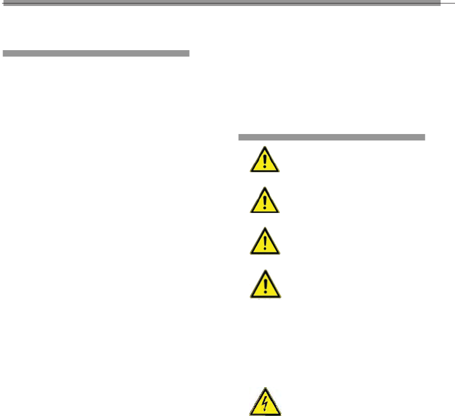
Camber
Camber is the leaning of the wheel inwards or
outwards from the vertical.
If the road wheel leans outwards from the vertical, it
has positive camber and when leaning inwards from
the vertical - negative camber, looking from the front
or rear of the vehicle. See Fig.1.1.
Fig.1.1
Camber is measured in degrees.
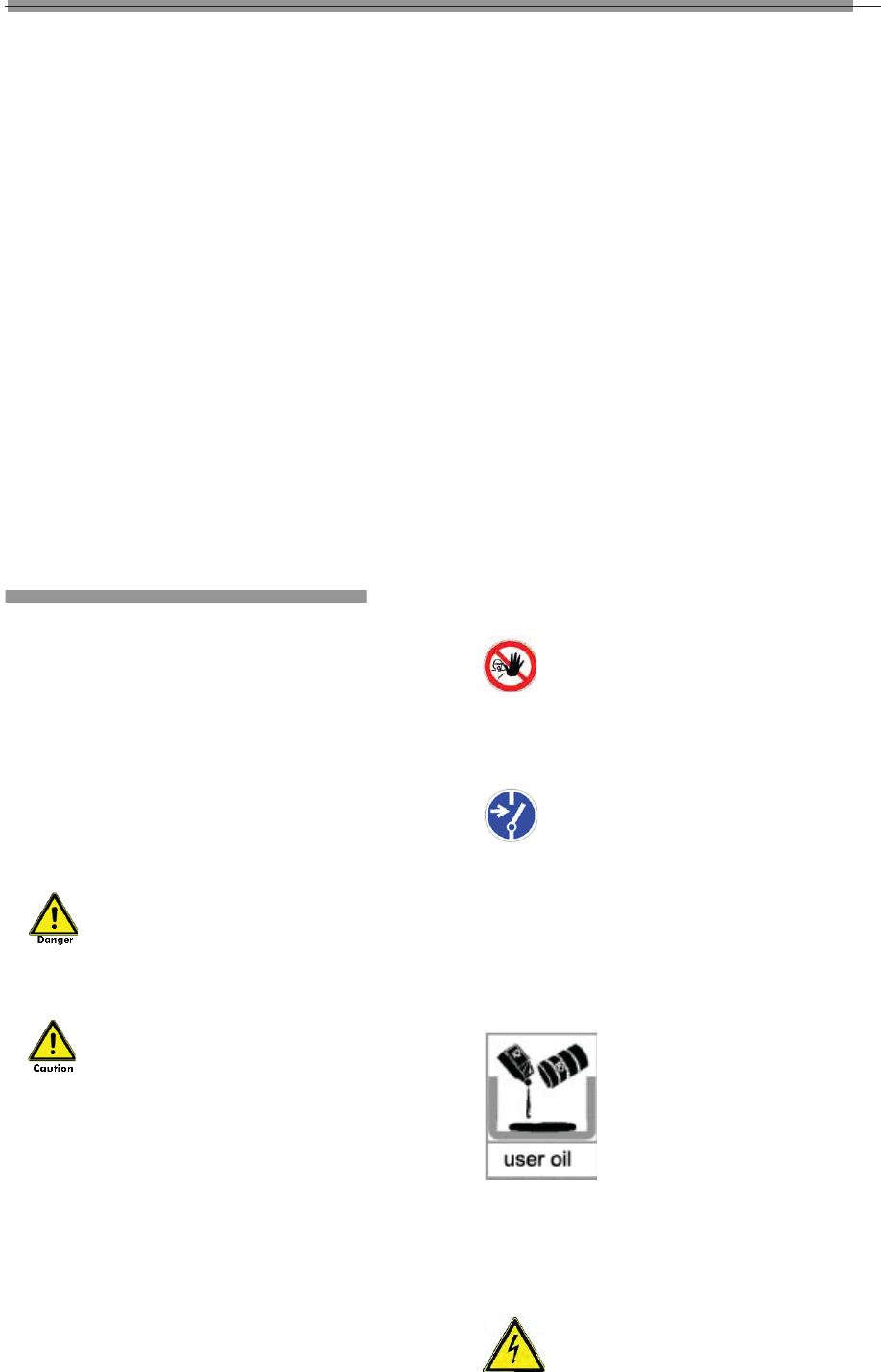
Toe-in and Toe-out
The toe setting is the amount by which the front or
rear wheels point inwards or outwards at the front of
the wheel in relation to each other (see Fig.1.2).
When the wheels point inwards they are said to toe-in.
Toe-in figures are given a positive value. Conversely
when the wheels point outwards they are toe-out and
the figures are shown as a negative value.
Fig.1.2
The purpose of correct toe is to ensure that the
wheels run parallel when the vehicle is driving. An
incorrect toe setting may affect the stability and
controllability of the vehicle.
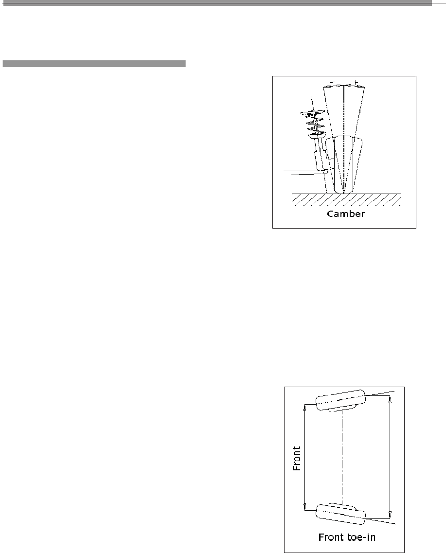
Kingpin Inclination (Steering Axle
Inclination SAI)
Kingpin Inclination (KPI or SAI) is the angle of
inclination of the king pin towards the centre-line of
the vehicle from the vertical (see Fig.1.3).
LAUNCH X-631/ X-631+ Wheel Aligner Introduction
1-2
Fig.1.3
Correct Kingpin Inclination can equalize the loads
applied on bearings so that the life of bearings can be
prolonged and the controllability of steering is
improved.
Without the inclination, the controllability of the
steering may be affected; further more, the vehicle
weight and the ground counterforce may cause
significant stress in the axle and finally damage the
axle.
Correct inclination of king pin is also helpful for the
vehicle to restore its straight-ahead position after
steering.
Kingpin Inclination is determined when the vehicle
suspension is designed. It is not service adjustable.
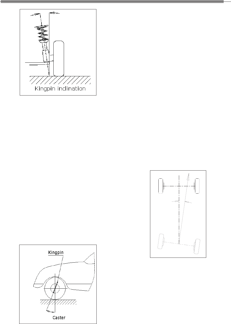
Caster
Caster is the tilting of the kingpin either forwards or
backwards from vertical, as viewed from side of the
vehicle. See Fig.1.4
Fig.1.4
When the king pin is tilted backwards from the vertical,
caster is positive. When the king pin is tilted forwards,
caster is negative.
Caster angle influences the directional stability of the
steering. To increase the tendency of the steering to
self-centre, the steering will normally be designed
with positive caster.
Thrust angle
The thrust angle is defined according to the driven
mode of vehicle.
zRear wheel driven: the thrust angle equals half of
the toe-in difference between the two rear wheels.
As shown in Fig.1.5.
zFront wheel driven: the thrust angle equals half
of the toe-in difference between the two front
wheels.
zFour-wheel driven: the thrust angle equals half of
the toe-in difference between the two front
wheels plus half of the toe-in difference between
the two rear wheels.
The thrust angle is defined as positive when the
thrust line is towards left and negative when the line
is towards right.
If the thrust angle is not zero, the vehicle will have the
side-moving trend. In this case, adjust the front toe-in
of the drive wheels first, and then adjust the toe-in of
driven wheels.
Fig.1.5
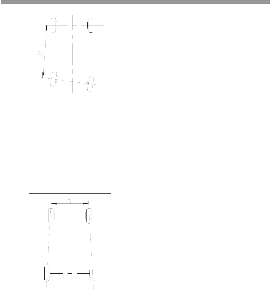
Wheelbase Difference
Wheelbase difference is defined as the angle
between the joint line of the centre of two rear wheels
and that of the front wheels. It is positive when
distance between the centre of the right wheels is
large than that of left wheels; and negative otherwise.
If the tread is available from the vehicle specifications,
then the wheelbase difference can be also expressed
by angle. See Fig. 1.6
LAUNCH X-631/ X-631+ Wheel Aligner Introduction
1-3
Fig. 1.6
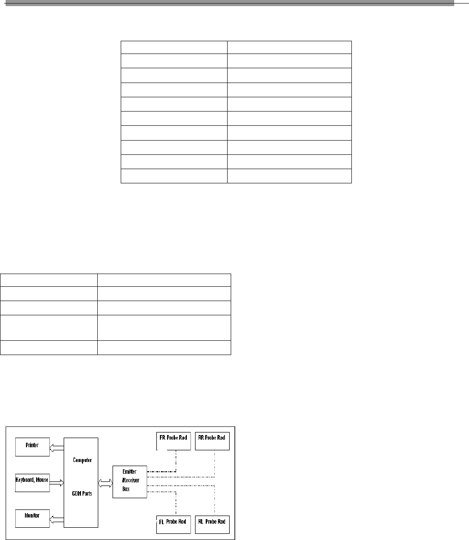
Track Width Difference
Track width difference is defined as the angle
between the joint line of the ground-contact point of
left wheels and that of the right wheels. It is positive
when distance between the centre of the rear wheels
is large than that of front wheels; and negative
otherwise. If the wheelbases are available from the
vehicle specifications, then the tread difference can
be also expressed by angle. See Fig. 1.7.
Fig. 1.7
Functions
zComplete test: The X-631/X-631+ Wheel Aligner
can be used to measure the most wheel
alignment parameters, such as front wheel
toe-in, front wheel camber, caster, Kingpin
inclination, rear wheel toe-in, rear wheel camber,
thrust angle, wheelbase difference, tread
difference, axle offset, front wheel setback and
rear wheel setback, etc.
zComplete databank: wheel alignment data of
over 10,000 vehicle models is stored in the
system. User can also add new data to the
databank.
zKingpin and camber adjustment real time
display function.
zHELP information for vehicle adjustment.
zLanguage operating prompt function.
zEmergency power supply and in-time charging
function.
zThe probe rods provide LCD display function.
zElectronic level function.
zBlack box self-diagnosis function.
zFront and rear probe rods interchangeable.
zSpecial test for Mercedes-Benz and BMW
vehicles.
Features
zInfrared 8-beam and 16-sensor loop
measurement, accurate and stable.
zNewly developed CCD signal processing
technology, nearly uninfluenced by the strong
sunlight.
zComplete system upgrading function.
zUnique voice prompt function and visualized
animation, very easy to understand.
zTrustworthy operating system to give more
convenient and safe operations.
zKeyboard quick switch operation.
zBoth special version and common version are
provided for user to select.
zBoth normal version and demonstration version
are provided to make user’s training more
convenient and quick.
zLarge capacity (4000mAh) Lithium battery with
low power consumption and dormancy mode of
design.
zCamber, toe-in, battery electricity quantity,
charging status and electronic level, etc. can be
real-time displayed by LCD.
zIn-block type of casting Aluminum alloy probe
rods can strongly guarantee the stability and the
test precision of the product.
LAUNCH X-631/ X-631+ Wheel Aligner Introduction
1-4
Specifications
Item Range
Front total toe-in f40嘙
Front toe-in f20嘙
Front camber f8.0嘙
Caster f20嘙
Kingpin inclination f20嘙
Rear total toe-in f40嘙
Rear toe-in f20嘙
Rear camber f8.0嘙
Thrust angle f5.0嘙
Notes:
1. The above measurement ranges can be confirmed only when the user follows the specified operation
procedures.
Requirements on Surroundings
Item Specification
Ambient temperature -10~+50ć
Relative humidity İ85%
Exterior magnetic
field strength İ400A/m
Lifter gradient İ1e
Working Principle
The working framework of X-631and X-631+ Wheel
Aligner is as shown in Fig.1.8.
Fig.1.8
LAUNCH X-631/X-631+ Wheel Aligner Structures
2-1
Structures
Overall Structure
X-631/X-631+ Wheel Aligner mainly consists of the
wheel aligner main unit, probe rods, wheel clamps,
turntables (optional), steering wheel holder, and brake
pedal depressor, etc.
Wheel Aligner Main Unit
The main unit is an operation control platform. It
consists of cabinet, computer group, interface circuit,
power supply assembly, etc., as shown in Fig.2.1.
The computer group includes computer, monitor,
keyboard, mouse, and printer. The monitor is on the
top platform of the cabinet. Mouse and keyboard are
on the keyboard drawer. Printer is on the drawer in
the middle of the cabinet. Thecomputerhost is in
the lower compartment of the cabinet.
The interface circuit includes the RF main emitter box.
The main emitter box is placed in the cabinet.
The power supply assembly includes power lead,
power socket, switch, and switch power. The power
switch is at the sideboard of cabinet. The power lead
is at the rear of the lower compartment inside the
cabinet. The power socket is at the spacer board and
near to the sideboard. The switch power supply is
also on the backboard of the cabinet.
Fig.2.1
Probe Rods
X-631/X-631+ is equipped with four probe rods. They
are FL, RL, FR and RR probe rods, as shown in
Fig.2.2. The front probe rods and the rear probe rods
can be across interchanged each other. If one of the
probe rods is changed, it is only necessary to
calibrate the changed probe rod, and the other three
probe rods needn’t be re-calibrated.
Fig.2.2 probe rod
Each probe rod is equipped with a CCD sensor at
end, and a blue-teeth emitter/receiver at the middle.
The CCD sensor picks-up the light pot coordinate and
transmit them to the computer through the blue-teeth
emitter. The computer processes the received
coordinate data signal.
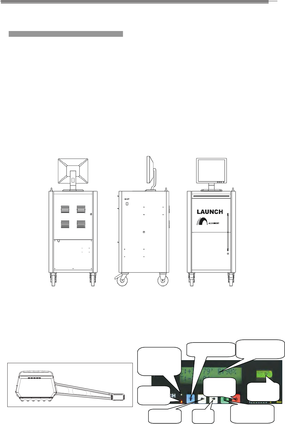
There is a button/LCD panel in the middle of each
probe rod as shown in Fig.2.3.
Fig.2.3
LCD Display
area
Power
Switch
LCD Rear Light
Previous Next Run-out
compensation
Level
bubble
Run-out
compensation
indicator
Power
indicator
LAUNCH X-631/X-631+ Wheel Aligner Structures
2-2
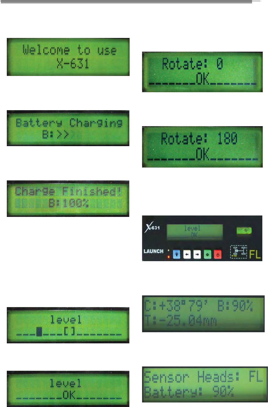
LCD display area has six functions: take the X-631 as
an example.
[Display start interface]: “Welcome to use X-631” is
displayed on LCD as shown in Fig.2.4.
Fig.2.4
[Display charging status]: “Battery Charging” is
displayed on LCD as shown in Fig.2.5. It indicates
that the battery is being charged.
Fig.2.5
“Charge Finished!” is displayed on LCD as shown in
Fig.2.6. It indicates that the battery charging is
finished.
Fig.2.6
Notes: When the characters of “>>>” are
displayed on LCD, it indicates that the probe rod
is being charged
Ģ
When “=D-”is displayed, it
indicates that the charging is finished, and the
cables are connected, the probe rod is powered
by the power supply from outside.
[Display electric level]: “level” is displayed on LCD. It
indicates that the level position adjustment is being
performed, and the black float mark indicates the
position of the bubble level as shown in Fig.2.7.
Fig.2.7
The probe rod is level when the black float mark turns
to “OK” as shown in Fig.2.8.
Fig.2.8
[Display for run-out compensation]: To display the
current compensation status of the probe rod: 0
indicates the run-out compensation operation should
be started for the current probe rod. The interface is
as shown in Fig.2.9.
Fig.2.9
90,180, 270 and 360 indicates respectively the
corresponding angles by which the tire should be
rotated. The interface is as shown in Fig.2.10.
Fig.2.10
After finishing the compensation operation for the
probe rod, the level status of the probe rod will be
displayed on LCD, and the run-out compensation
indicator on the control panel of the probe rod will turn
green. The interface is as shown in Fig.2.11.
Fig.2.11
[Display probe rod measurement]: Real-time display
Camber (C), Toe-in (T) and Battery electricity quantity
(B) as shown in Fig.2.12.
Fig.2.12
[Display probe rod status]: Display the position of
probe rod and the electricity quantity of battery as
shown in Fig.2.13.
Fig.2.13
LAUNCH X-631/X-631+ Wheel Aligner Structures
2-3
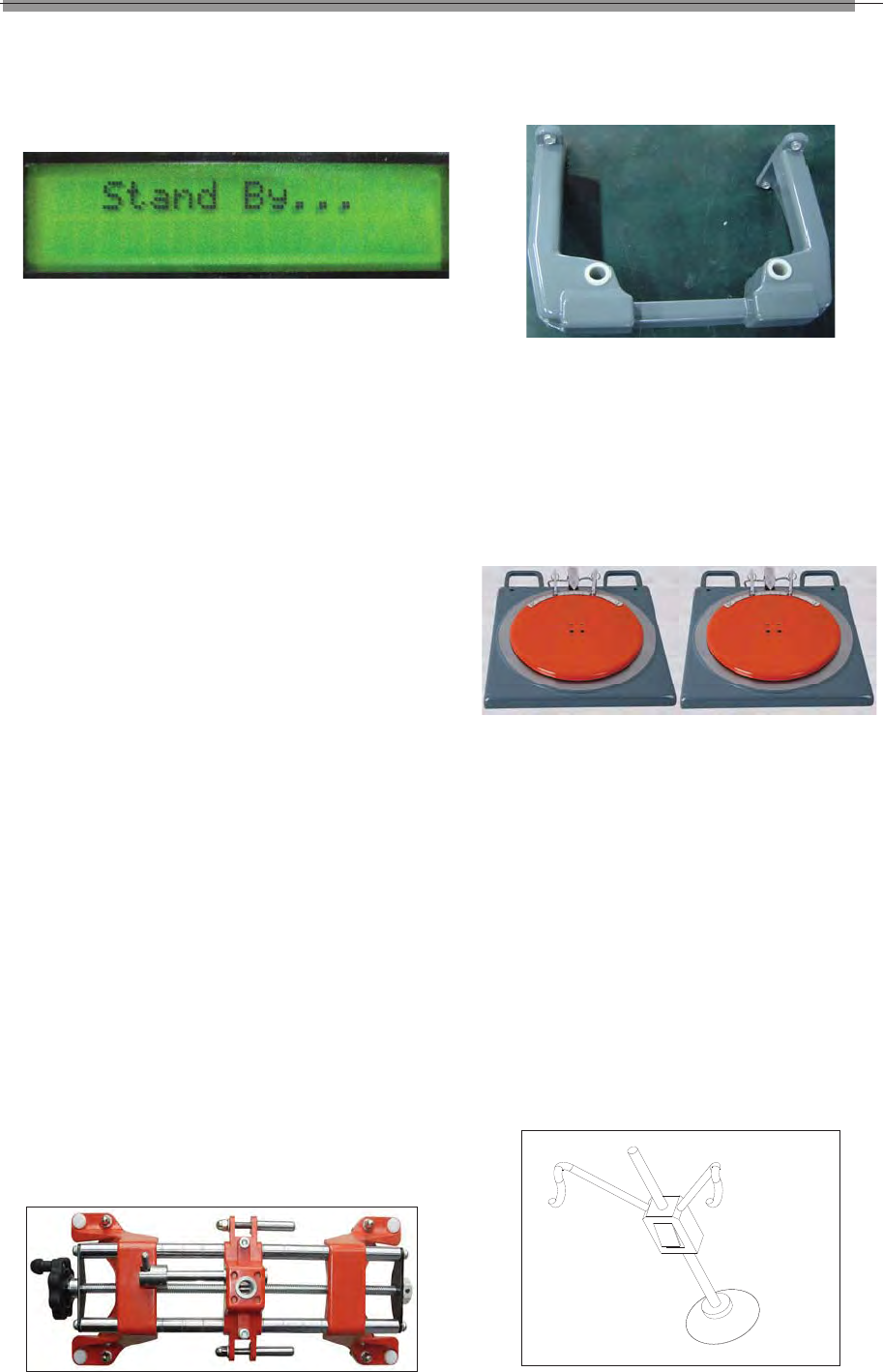
[Display Standby status]: “Stand By…” is displayed
on LCD. It indicates that the probe rod is in standby
mode for saving electricity. The standby mode can be
switched to normal working mode as shown in
Fig.2.14.
Fig.2.14
Button area includes 5 buttons:
[Backlight]: Key to switch on/off the backlight of LCD.
[Next]: To perform the test according to the default
sequence (Select Vehicle Model Run-out
Compensation Kingpin Measurement Rear
Axle Measurement Front Axle Measurement
Print Report Form ) of the system.
[Previous]: To return to the previous operating
procedure during test.
[Run-out compensation]: It is the special key-press for
run-out compensation operation.
[Power switch]: Switch on/off the battery power
supply of the probe rod.
There is a 9V power supply socket on the side wall of
the probe rod box. It is used for charging the battery
of the probe rod. When the electricity quantity of the
battery is full, the charging circuit will automatically
stop charging.
Caution! Make sure to turn off the power of the
probe rod before charging it. The probe rod is a
precision component; please handle it with care
to ensure measuring accuracy.
Wheel Clamps
X-631/X-631+ has 4 wheel clamps (see Fig.2.15).
Turn the adjusting knob to adjust the span between
wheel claws, and then attach the clamp to the wheel
rim. Adjust the knob to make the wheel clamp fixed
on wheel rim tightly. Use the wheel clamp tie to bind
the wheel clamp and the wheel rim together.
The installation of wheel clamp is crucial to the test
result. The claws should be in even contact with the
wheel rim without touching the lead weight.
Avoid hitting during operation. Otherwise, distortion
may be caused and the test result may be influenced.
Fig.2.15
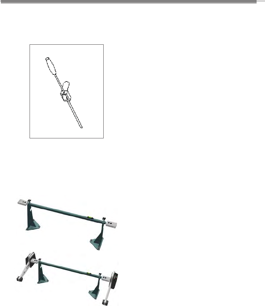
Wheel Clamp Hanging Bracket
X-631/X-631+ wheel aligner is equipped with 4 wheel
clamp hanging brackets as shown in Fig.2.16.
Fig.2.16
After unpacking, it is necessary to install these 4
hanging brackets on left and right side wall of the
cabinet.
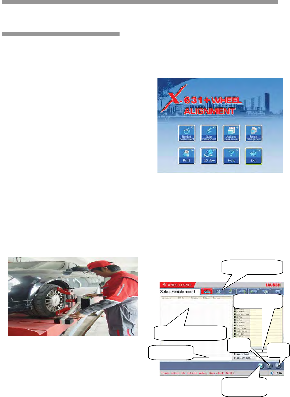
Turntables
X-631/X-631+ has two mechanical turntables
(standard configuration, see Fig.2.17).
Fig.2.17 mechanical turntables
When testing, the turntables should be placed at the
front wheel position of vehicle on the lift.
Use the lock pin to lock the turntable before driving
the vehicle on. Pull out the lock pin after the vehicle is
stopped and the front wheels are at the center of the
turntables.
While testing, try your best to keep the vehicle front
wheel at the center of the turntable.
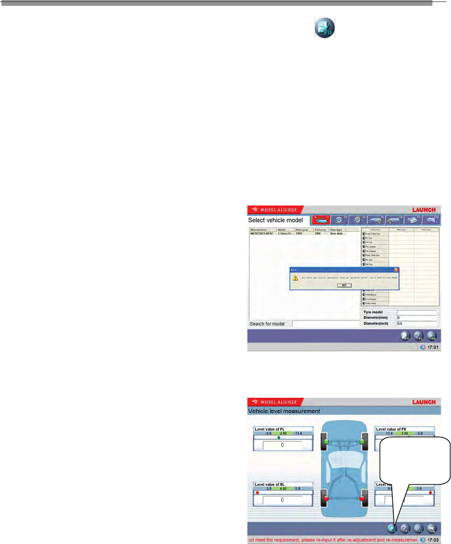
Steering Wheel Holder
X-631/X-631+ has a steering wheel holder as shown
in Fig.2.18. Use the steering wheel holder to lock the
steering wheel according to the tips on the screen.
Fig.2.18 Steering wheel holder
LAUNCH X-631/X-631+ Wheel Aligner Structures
2-4
Brake Pedal Depressor
X-631/X-631+ has a brake pedal depressor is as
shown in Fig.2.19. It is used to hold the brake pedal
down.
Fig.2.19 Brake pedal depressor
Calibrating Frame and its
Converter Connector (Optional)
They are mainly used to calibrate the probe rod
system of X-631/X-631+ wheel aligner.
Fig.2.20 Calibrating frame and its converter connector

LAUNCH X-631/X-631+ Wheel Aligner Basic Operation Procedures
3-1
Basic Operation
Procedures
Get Vehicle Information
Ask the owner for vehicle drivability problems,
symptoms, and wheel alignment history, and find out
vehicle information such as make, model and year,
etc.
Check each chassis part carefully, include dust cover,
bearing, rock arm, tripod-ball, shock absorber, tie rod
ball and steering mechanism, for any loose or wear.
Then check to see if the tire pressure, tire treads of
the left and right wheels are alike.
Wheel Alignment Checking
Perform the wheel alignment checking after the initial
condition is known.
Adjustment
If the measuring values do not accord with the
specifications given in the databank, the wheel
alignment should be adjusted.
Test-drive
After finishing the wheel alignment, test the vehicle to
see if the abnormal conditions are eliminated.
Re-adjust the wheel alignment if necessary.
LAUNCH X-631/X-631+ Wheel Aligner Operation Instructions
4-1
Operation Instructions
Preparation
I. Drive the vehicle onto the lift or over the pit, so
that the front wheels are centered to the
turntables; Apply hand brake to ensure safety. To
prevent the turntable from turning, lock the
turntables with the lock pins before driving the
vehicle; release the lock pins after the vehicle is
well-positioned.
II. Ask the owner for vehicle drivability problems and
symptoms, wheel alignment history, and find out
vehicle information such as make, model and
year, etc.
III. Check each chassis part carefully, include dust
cover, bearing, rock arm, tripod-ball, shock
absorber, tie rod ball and steering mechanism,
for any loose or wear. Then check to see if the
tire pressure and treads of the left and right
wheels are alike.
IV. Install the wheel clamps on the four wheels in
turn and turn the knobs to lock the wheel clamps.
The claws of the wheel clamp should be fixed on
the external or internal edge of the rim according
to the practical condition. Ensure equal depth for
each claw and avoid attaching it on the distorted
area.
V. Install the probe rods on the pinbushes of
wheel clamps as shown in Fig.4.1.
Fig.4.1
VI. Level the probe rod by adjusting the bubble in the
level gauge to the center position.
VII. Plug the power cable of the Wheel Aligner into a
standard power outlet of 3PIN. Switch on the
power supply of the cabinet and start the
computer.
VIII. Place the steering wheel holder on the driver seat;
and press the handle to lock the steering wheel.
IX. Put the brake pedal depressor between the brake
pedal and the driver seat to keep the brake
applied.
Operation procedures
Turn on the power switch, start the computer and
enter the main interface of the measurement program.
The screen displays the main function menu. There
are 8 functions available in the main menu: [Standard
Measurement], [Quick Measurement], [Additional
Measurement], [System Management], [Print], [2D
Interface/3D Interface], [Help], and [Exit]. See Fig.4.2
Fig.4.2
Standard Measurement
Click [Standard Measurement] in the interface as
shown in Fig.4.2. The screen system will enter the
standard measurement interface.
Select Vehicle Model
Before alignment, the standard data of the vehicle
model must be selected first. The interface is as
shown in Fig.4.3:
Fig.4.3
[Next]: To perform the test according to the default
sequence (Select vehicle model ė Run-out
compensation ė Kingpin measurement ė
Rear axle measurement ė Front axle
measurement ėPrint report form ) of the system.
Next
Help
Quick search
Commonly used data list
Navigation column
Tire parameter
Selected from
standard data
LAUNCH X-631/X-631+ Wheel Aligner Operation Instructions
4-2
[Navigation column]: To enter into the item you want
to test in spite of the default sequence.
[Commonly used data list]: The vehicle model in the
list can be directly selected to perform the next-step
operation. It is blank when firstly used. Only the
vehicle model data must be added into this list from
the standard database, can the list be used (See
[System Management] - [Commonly used data
management]).
[Selected from standard data]: If there is no the
vehicle model you want, you can directly search for
the vehicle model you want from the standard
database, and directly perform the next-step
operation˄This vehicle model is no longer saved in
the commonly used data list˅. If you want to add this
vehicle model into the commonly used data list, it
needs to be added from the interface of [System
Management] - [Standard Data Management]).
[Quick search]: The input box for quick search aiming
at the vehicle model is provided at the bottom of the
interface. Please input the first letter of the vehicle
model to perform the searching operation.
[Tire parameter]: When the unit of toe-in is used in
mm or In (The unit of toe-in can be set in [System
Management] – [System setting]), the diameter of the
present tire must be input.
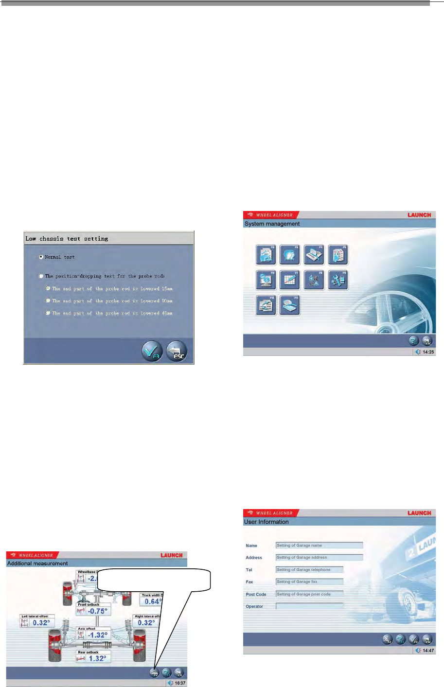
[Low chassis measurement setting]: When test the
vehicle with the low chassis, please use this setting to
perform the measurement for the intelligent position-
dropping of the probe rod's end part, in order to solve
the problem of blocking the sensors when testing the
vehicle with the low chassis. This setting can be
automatically reset when re-selecting the vehicle
model or exiting the test system. Caution: After the
probe rod's position dropped, the level adjustment
should take the electronic level as the standard.
[Help]: To provide the description of operating method
and note.
Operating procedures:
Select the corresponding vehicle model item in
[Commonly used data list], then click [Next].
Note:
1. When the toe of the system uses linear measure,
it is required to enter the vehicle tire diameter at
the right bottom corner on this interface,
otherwise the system cannot enter the next
operating procedure
2. The form currently provided is the same form
with Commonly Used Data Management in the
System Management interface, in the same way,
you can click button to add the standard
data provided by the system into this form. If you
want to add user-defined data, you need to add it
from Standard Data Management interface of
System Management. The unit of Wheelbase,
Front wheelbase and Rear wheelbase is mm.
Special Measurement:
For different data of vehicle model, some special
measurement methods and operating procedures will
occur:
1. Aiming at some vehicle model of Benz, the
system provides the operations for measuring
the standard data with gradient meter. When the
data selected is of Benz vehicle, the system will
pop up a dialogue box as shown in Fig.4.4.
Fig.4.4
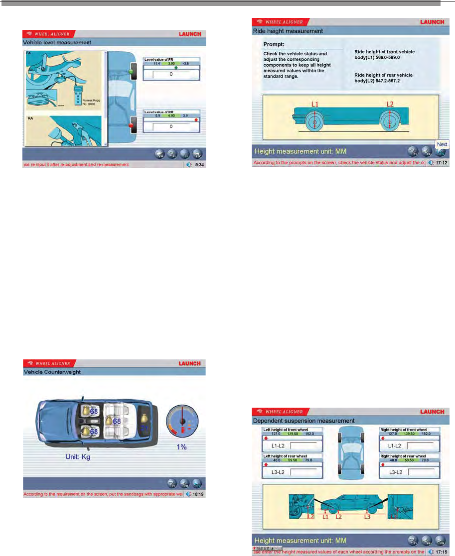
The interface for vehicle level measurement is
displayed in Fig.4.5.
Fig.4.5
Use gradient meter—the special measurement
instrument (optional) to get the level values of four
wheels, which are displayed in the editing boxes. Also,
the operator can take the level value scopes
displayed on the top of the editing boxes as the
reference, and manually input the corresponding level
values of four wheels.
[Vehicle Adjustment Help]: It provides the using
method of the gradient meter for Benz vehicle, the
operator can perform the vehicle test and adjustment
with the reference of the operating methods in Help
Vehicle
adjustment
Help
LAUNCH X-631/X-631+ Wheel Aligner Operation Instructions
4-3
interface as shown in Fig.4.6.
Fig.4.6
Operating procedures:
According to the prompts on the interface of [Vehicle
adjustment Help], please perform the level
measurement for four suspensions by the way of
using the gradient meter, and then connect the
gradient meter to the computer host, the system will
confirm the standard data of current vehicle model
according to each level value measurement by the
gradient meter.
2. When some special vehicle models (such as
BMW 3 series) are selected, the screen will pop
up an interface of [Vehicle Counterweight] as
shown in Fig.4.7.
Fig.4.7
According to the requirements on the interface, put
the sandbags with appropriate weight on the vehicle
seats or in the baggage case, and fill the oil tank
according to the requirement. Please click [NEXT]
button to perform the next operation after finishing the
previous procedures.
3. When some special vehicle models (such as
BMW 3 series) are selected, the screen will pop
up an interface of [Height Measurement] as
shown in Fig.4.8. This interface provides an
operating platform for ride height measurement
system, in order to check if the ride height meets
the design requirements of OEM.
Fig.4.8
Operating methods:
According to the prompts on the picture at the bottom of
the interface, measure left, right, front and rear ride
height values respectively to see if they are within the
standard range or not. If the height measurement
value(s) is (are) not within the standard range, please
check the vehicle status, and adjust the corresponding
components to keep 4 Height Measurement Values
within the standard range. Click [NEXT] after finished.
4. When some special vehicle models (such as
RENAULT MEGANEĊ) are selected, the screen
will pop up an interface of [Dependent
Suspension Measurement] as shown in Fig.4.9.
This interface provides an operating platform for
dependent suspension measurement system, in
order to confirm the standard data according to
the current status of the vehicle body.
Fig.4.9
Operating methods:
According to the prompts on the picture at the bottom
of the interface, measure left, right, front and rear ride
height values respectively, and input them into the
corresponding inputting boxes. Click [NEXT] after
finished.
Caution:
1). Testing conditions for ride height measurement
zSpecified tire pressure
zGood and even tread pattern
zSpecified wheel bearing clearance
LAUNCH X-631/X-631+ Wheel Aligner Operation Instructions
4-4
zSpecified rim and tire
zThe brake pedal depressor is installed
zCounterweight the whole vehicle
according to the normal driving
conditions. Adjust the seats to the
middle positions and fill the gasoline
tank full.
2). If the measured values are beyond the tolerance
range, it indicates that the vehicle is faulty, and the
faults must be eliminated before performing the ride
height measurement.
3). For the vehicle with air shock absorbers, please
pull out the security device of the air feeding
equipment to prevent the vehicle from being
adjusted up and down.
4). The sandbags and height measurement meter are
not delivered with the instrument, users should
prepare them by themselves.
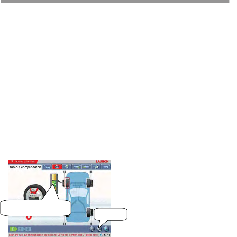
Run-out Compensation
This function is to reduce the error caused by the
distortion of the wheel rim and tire. It is advisable to
select this function to ensure measuring accuracy.
The interface is as shown in Fig.4.10.
Fig.4.10
[Icon for the level status of probe rod]: To indicate the
level status of the present probe rod. Green indicates
the probe rod is level and red indicates not level.
[Previous]: To return to the previous operating
procedure.
Operating procedures:
1. Keep the vehicle wheels on straight-ahead
positions, fix the steering wheel with the steering
wheel holder, remove the brake pedal depressor
to keep the wheels can be freely rotated.
2. Install four wheel clamps and probe rods, and
then adjust each probe rod level respectively.
3. According to the prompts on the screen, start the
run-out compensation operation for LF wheel.
Adjust LF probe rod level, and click [NEXT] after
finished.
4. According to the prompts on the screen, turn LF
wheel by 180°. Adjust LF probe rod level, and
click [NEXT] after finished.
5. According to the prompts on the screen, turn LF
wheel by 360°. Adjust LF probe rod level, and
click [NEXT] after finished.
6. According to the prompts on the screen, perform
the run-out compensation operation for RF, RR
and LR wheel respectively.
7. Put down the vehicle body, keep the four wheels
on the ground. Shake the vehicle body, keep four
wheels cling to the ground, the run-out
compensation operation is finished (The
interface displays the values of run-out
compensation).
Caution:
1. Before performing run-out compensation
operation, be sure to fix the steering wheel
according to the requirements, in order to avoid
the wheels' swing to left or right when performing
run-out compensation operation, causing the
inaccurate run-out compensation.
2. You are required to swing the vehicle tires when
performing the run-out compensation operation.
Keep each probe rod to be at rest comparatively
and level (if some probe rod is not level during
operating, the system cannot perform the next
operation until the probe rod is adjusted level).
3. If the left wheels and right wheels of some
vehicles are linked (i.e. when left wheel rotates,
the right wheel rotates, too), and you want to
perform run-out compensation operation, you
must hold the right (left) wheel when you rotate
the left (right) wheel, and you should notice that
force from you hands must be balanced (in order
to avoid wheel's swing to left and right and
causing inaccurate run-out compensation).
Meanwhile you should check if the probe rods
are level or not. If not, it is necessary to adjust
the probe rods level by the way of rotating the
wheels. You should note that the probe rods
mustn't be adjusted level by the way of loosing
them.
4. If the second-time lift can put up the front and
rear axles at the same time, the front and rear
axles should be put up at the same time when
performing the run-out compensation operations;
if the second-time lift can only put up one axle at
a time, please put up the front axle individually
when performing the front wheel run-out
compensation operations, and put up the rear
axle individually when performing the rear wheel
run-out compensation operations.
5. Three types of run-out compensation operation
modes (90°, 180° and rolling run-out
compensation) can be set on the interface of
[System Management]-[System Setting].
180°run-out compensation mode is a standard
one. It is with high accuracy, and cross reference
between front and rear probe rod is necessary
The icon for the level status
of
p
robe rod Previous
LAUNCH X-631/X-631+ Wheel Aligner Operation Instructions
4-5
for the measurement under this mode; the
accuracy of 90°run-out compensation mode is
comparatively lower, but each probe rod can
finish run-out compensation operation
independently under this mode, needless to take
other probe rod as reference. This run-out
compensation operation mode can be selected in
the case of CCD sensor cannot work normally
caused by second-time lift or other factors; it is
not required to lift up the vehicle during rolling
run-out compensation operation. Only
vehicle-pushing is required to accomplish the
run-out compensation operation. Among the
three kinds of run-out compensation modes
mentioned above, the accuracy of rolling run-out
compensation is lowest.
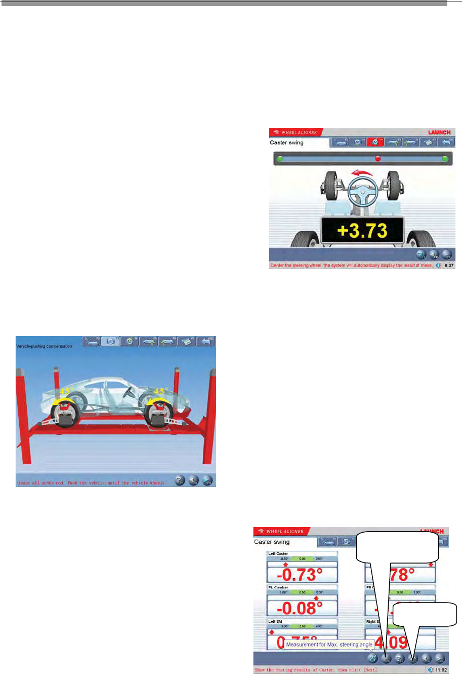
Vehicle-pushing Run-out Compensation
Vehicle-pushing run-out compensation is mainly used
for getting the inherent parameters of the four wheels
before the normal measurement, so as to ensure the
measurement more accurate. You do not always
perform this operation. If the measurement is
accurate, the user can directly skip this step, and start
from Caster Swing measurement. The interface is as
shown in Fig.4.11:
Fig.4.11
Operating procedures:
1. Turn the steering wheel to make the front wheels
on straight-ahead position. Hold the steering
wheel with the steering wheel holder, and then
remove the brake pedal depressor;
2. Respectively install four wheel clamps and probe
rods, and then adjust each probe rod level;
3. Release all four probe rods respectively, and
push the vehicle back by 45°, and then adjust all
probe rods level. Please click [NEXT] after
finished;
4. Push the vehicle back to the original position,
and then adjust all probe rods level. Please click
[NEXT] after finished.
Caster Swing
Kingpin measurement is aimed at the front wheels,
which includes kingpin inclination and caster. Correct
Kingpin Inclination can equalize the loads applied on
bearings so that the life of bearings can be prolonged
and the controllability of steering is improved. The
existence of kingpin inclination can make the
intersection point of steering axes and road surface
be in front of the adherent point between tire and the
ground, which can make use of the resistance from
the road surface to the tire to keep the vehicle driven
straight-ahead. The interface is as shown in Fig.4.12.
Fig.4.12
Operating procedures:
1. Adjust the steering wheel to straight-ahead status,
i.e. when the toe-in of FL wheel is equal to the
toe-in of RF wheel, the small round ball on the
operating interface will move to middle position
and turn green from red. At this moment you can
adjust all probe rods level.
2. Turn the steering wheel left or right, after arriving
at the desired position, the small ball turns green
again from red. It indicates that the acquisition for
this side is finished.
3. Center the steering wheel, and turn it in reverse
direction, after arriving at the desired position, the
newly created small ball turns green again from
red, and the acquisition is finished.
After test finished, please center the steering
wheel. The system will automatically return to the
next page to check the measurement result. The
interface is as shown in Fig.4.13.
Fig.4.13
[Measurement for Max. steering angle]: According to the
prompts on the screen, read the data of Max. steering
anglesindicated by mechanical turntables for FL and
HELP for vehicle
ad
j
ustment
Detailed data
LAUNCH X-631/X-631+ Wheel Aligner Operation Instructions
4-6
FR wheels, and input them into the corresponding data
boxes respectively, and then click [Return]. The interface
is as shown in Fig.4.14.
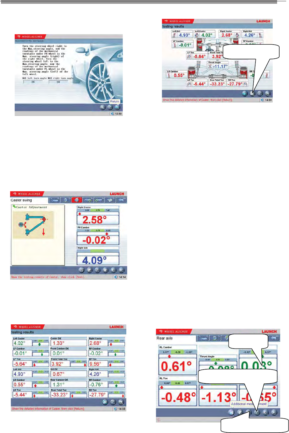
Fig.4.14
[HELP for vehicle adjustment]: Click this button, the
screen will pop up an interface of [HELP for vehicle
adjustment], the different kingpin adjusting methods for
various vehicle models have been enumerated in this
interface for vehicle adjustment, the operator can
perform the kingpin adjustment operation according to
the operating methods in the HELP interface. The
interface is as shown in Fig.4.15
Fig.4.15
[Detailed data]: This interface provides the result outputs
for whole testing operations, which includes the
measured values of each parameter for front and rear
wheels. The interface is as shown in Fig.4.16.
Fig.4.16
[Figure format]: Figure format data display mode is
newly added in the system. Click [Word Format] button
to switch it between Traditional Data Format and
newly-added Figure Format. The interface is as shown
in Fig.4.17.
Fig.4.17
Caution:
1. Before perform kingpin measurement, please
install brake pedal depressor and lock the hand
brake first, in order to ensure the vehicle wheels
cannot move; remove the steering wheel holder
finally.
2. The steering angle for [Kingpin Steering
Operation] can be set on the interface of [System
Setting]. The standard kingpin measurement is
the measurement of 20-degree-steering. But in
some special cases, 10-degree-steering
measurement can be selected when the steering
angle cannot be up to 20 degrees.
3. The measured values are displayed with different
colors on each measurement interface.
zGreen, it indicates that the measured values
are within the standard specifications.
zRed, it indicates that the measured values
are beyond the standard specifications.
zBlue, it indicates that this measured
parameter has not the standard
specification.
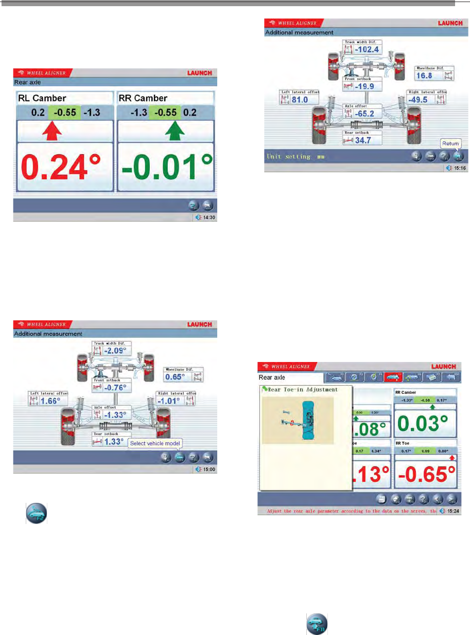
Rear axle measurement
This interface can provide the real-time result related to
rear axle measurement, the operator can compare the
measurement result with the reference data while
adjusting the vehicle, until the vehicle is adjusted to the
best status. The interface is as shown in Fig.4.18.
Fig.4.18
Double click
HELP for vehicle adjustment
Language format
Put up the vehicle body
LAUNCH X-631/X-631+ Wheel Aligner Operation Instructions
4-7
[Double click]: Double click (with left key of the mouse)
on the data display forms for camber and toe-in of RL
and RR wheels, the corresponding displayed data will
be enlarged. The interface is as shown in Fig.4.19.
Fig.4.19
[Additional Measurement]: This interface provides an
operating platform for special measurement, which can
measure and display left lateral offset, right lateral offset,
axle offset, front setback, rear setback, track width
difference and wheelbase difference, etc. The interface
is as shown in Fig.4.20.
Fig.4.20
Click pushbutton to select the parameters of
standard vehicle model. If the parameter values of
wheelbase and front/rear track width are contained in
the standard database, each angle value displayed on
the screen will automatically be converted into length
value with the unit of mm. The interface is as shown in
Fig.4.21.
Fig.4.21
Note: The system provides the dynamic measurement
and display for these special values, but the
measurement result will not be saved in the database.
[HELP for vehicle adjustment]: Click this button, the
screen will pop up an interface of [HELP for vehicle
adjustment], the different toe-in and camber adjusting
methods for various vehicle models have been
enumerated in this interface for vehicle adjustment, the
operator can perform the toe-in and camber adjustment
operation according to the operating methods in the
HELP interface. The interface is as shown in Fig.4.22.
Fig.4.22
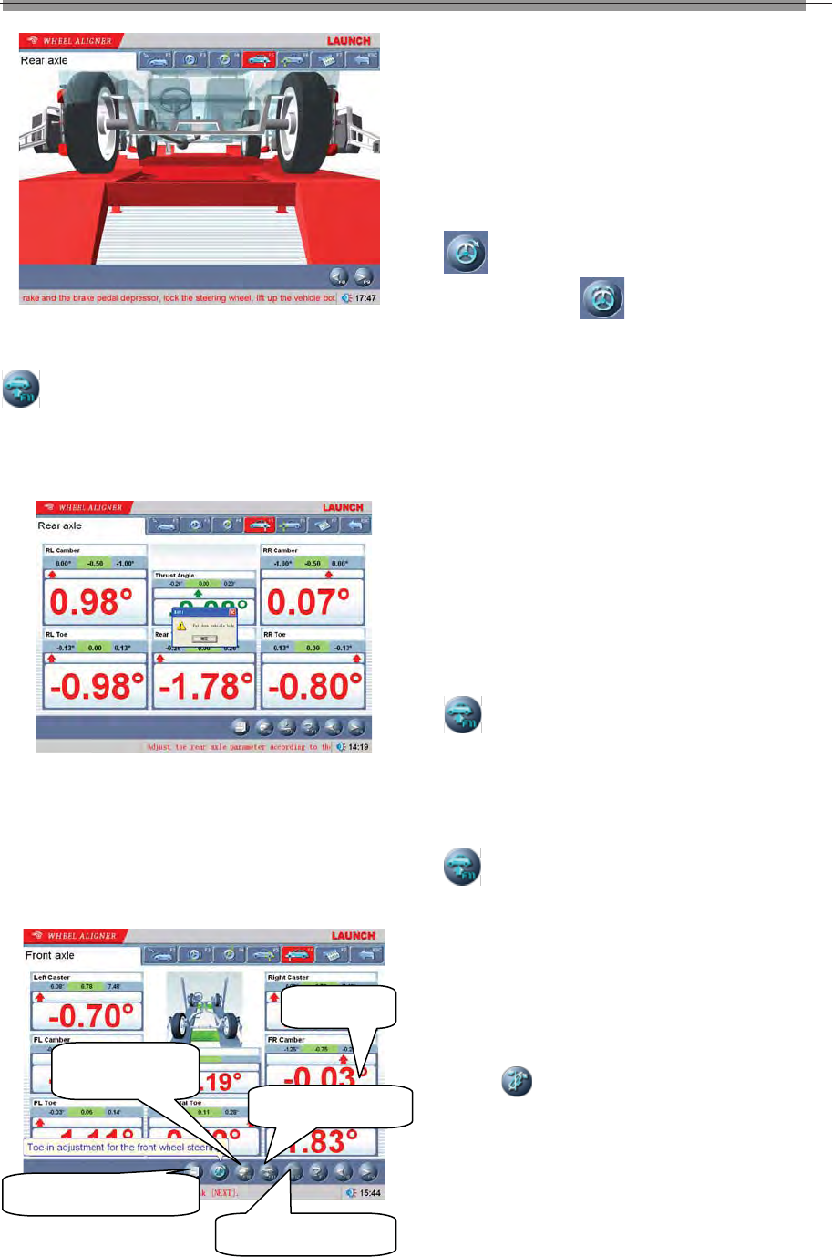
[Lift up the vehicle body]: Sometimes it is required to lift
the vehicle body up in order to be convenient to adjust
front/rear camber and caster.
When the vehicle wheels are lifted up, the inclinometers
will move, and the corresponding measured values will
change, too. In this case, please use Lifting Adjustment
function. Click button, and then lift up the vehicle
body according to the prompts on the screen. The
software will automatically compensate the offset of
inclinometer in order to realize accurate adjustment.
LAUNCH X-631/X-631+ Wheel Aligner Operation Instructions
4-8
Fig.4.23
Attention: After adjustment, please remember to click
button, and then put down the vehicle body
according to the prompts on the screen. If the lift is not
put down, it will be limited to select the other interfaces
(except for [Front axle measurement] interface) as
shown in Fig.4.24.
Fig.4.24
Front axle measurement
This interface can provide the real-time result related to
front axle measurement, the operator can compare the
measurement result with the reference data while
adjusting the vehicle, until the vehicle is adjusted to the
best status. The interface is as shown in Fig.4.25.
Fig.4.25
[Double click]: Double click (with left key of the mouse)
on the data display forms for camber and toe-in of LR
and RR wheels, the corresponding displayed data will
be enlarged.
[Additional measurement]: This interface provides an
operating platform for special measurement, which can
measure and display left lateral offset, right lateral
offset, axle offset, front setback, rear setback, track
width difference and wheelbase difference, etc.
[Toe-in adjustment for the front wheel steering]: Click
to perform toe-in adjustment for front wheel
steering, and click to center the steering wheel
(Note: When using two probe rods to perform the
measurement operation, only total toe-in is displayed,
and individual toe-in is not displayed).
[HELP for vehicle adjustment]: Click this button, the
screen will pop up an interface of [HELP for vehicle
adjustment], the different adjusting methods for various
vehicle models have been enumerated in this interface
for vehicle adjustment, the operator can perform the
vehicle adjustment operation according to the
operating methods in the HELP interface.
[Lift up vehicle body]: Sometimes it is required to lift the
vehicle body up in order to be convenient to adjust
front/rear camber and caster. When the vehicle wheels
are lifted up, the inclinometers will move, and the
corresponding measured values will change, too. In
this case, please use Lifting Adjustment function. Click
button, and then lift up the vehicle body
according to the prompts on the screen. The software
will automatically compensate the offset of inclinometer
in order to realize accurate adjustment.
Attention: After adjustment, please remember to click
button, and then put down the vehicle body
according to the prompts on the screen
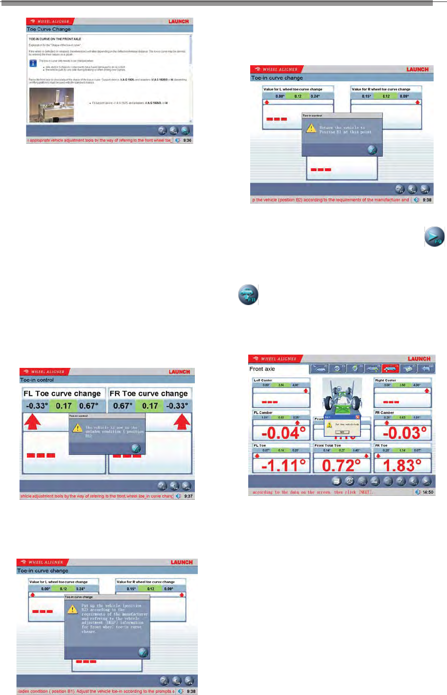
[Toe-in curve change] provides the special
measurement methods relative to some vehicle models
of VOLKSWAGE and AUDI, etc. First, the operator
must adjust the toe-in curve changes of these kinds of
vehicles to the standard range, and then Front Axle
Measurement can be performed normally. When
[Toe-in Curve Change] is activated, please click the
icon of , the screen will display the interface as
shown in Fig.4.26.
Double click
HELP for vehicle
ad
j
ustment
Lift up vehicle body
Additional measurement
Toe-in curve change
LAUNCH X-631/X-631+ Wheel Aligner Operation Instructions
4-9
Fig.4.26
Operating Methods:
1. Click [Toe-in Curve Change] on the interface of
[Front Axle Measurement] to enter Toe-in Curve
Change interface as shown in Fig.4.24.
2. According to the prompts on the screen, please
select the appropriate vehicle adjustment tools by
the way of referring to the vehicle adjustment
HELP information for the front toe-in curve change
regulator. Please perform the next operation
procedure after finished.
3. The vehicle is now in put-down status (position B1).
Adjust the vehicle front toe-in to the allowed scope
according to the standard specifications (see
Fig.4.25). Put up the vehicle with the special tools
equipped according to the prompts on the screen.
Click [NEXT] button, the screen will display the
interface as shown in Fig.4.27.
Fig.4.27
4. Put up the vehicle (to position B2) according to the
requirements of the manufacturer. The screen
display the interface as shown in Fig.4.28:
Fig.4.28
5. Put down the vehicle to position B1. Adjust the
vehicle front toe-in to the allowed scope according
to the standard specifications. The interface is as
shown in Fig.4.29:
Fig.4.29
6. Put down the vehicle, and then click
button to return to the interface of [Front Axle
Measurement].
Attention: After adjustment, please remember to click
button, and then put down the vehicle body
according to the prompts on the screen. If the lift is not
put down, it will be limited to select the other interfaces
(except for [Rear axle measurement] interface) as
shown in Fig.4.30.
Fig.4.30
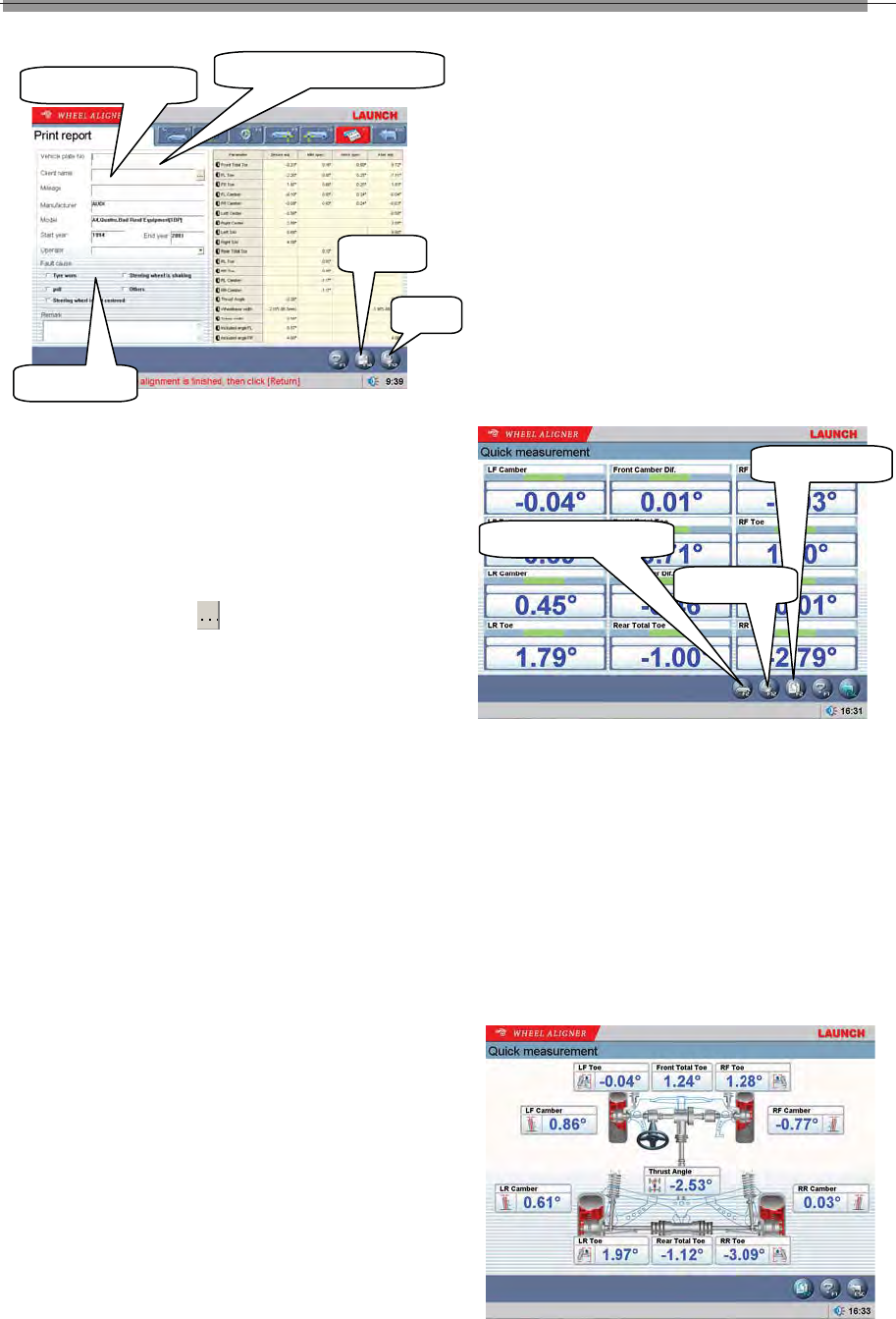
Print Report
Print Report can print and save the alignment data of
the vehicle under test. The interface is as shown in
Fig.4.31.
LAUNCH X-631/X-631+ Wheel Aligner Operation Instructions
4-10
Fig.4.31
[Vehicle license plate number]: The license plate
number of the vehicle under test.
[Client information]: The corresponding information for
the owner of the vehicle under test, including [Client
name], [Contact], [Telephone] and [Address]. The client
information cannot be directly entered in this interface
with the keyboard. Icon behind [Client name] must
be clicked to enter the interface of [Client Management],
and then the corresponding [Client information] can be
selected. If information of this client is not available in
[Client Management], it must be added first before
selection (Please refer to [Configuration] – [Client
management]).
[Vehicle information]: The corresponding information of
the vehicle under test, including [Mileage],
[Manufacturer], [Model], [Start year] and [End year].
The vehicle information cannot be directly entered in
this interface with the keyboard. If the vehicle model
has been selected in [Measurement] – [Select vehicle
model], the corresponding information of the vehicle
model selected will be displayed in this interface. If not,
no any information is displayed in this interface.
[Operator]: Name of the operator who is operating
the instrument now. The corresponding [Operator] can
be selected only after the [Operator] column of
[Information for service station] is added (Please refer
to [System management] – [User information]).
[Fault cause]: The symptoms of the vehicle under test.
There are 5 options: [Tire wear], [Pull], [Steering wheel
is not centered], [Steering wheel swings] and [Others].
[Save]: To save the alignment data of the vehicle under
test ([Vehicle plate number] and [Client name] must be
entered, and [Fault cause] must be selected first before
saving).
[Print]: To print the alignment data of the vehicle under
test in the format of form or image (Please refer to
[System management] – [Report setting] for the format
setting of the report form).
Caution: The report form print function provided by this
interface only aims at the individual information report
form for the test at this time; the report form print
function provided by the main interface aims at all the
information report forms saved and done before.
Quick Measurement
Select [Quick measurement] icon on the main menu,
the system will enter the [Quick measurement]
interface. This interface provides an operating platform
for quick measurement, which can test and display
toe-in and camber of front and rear wheels at the same
time. The interface is as shown in the following figure:
Fig.4.32
[Select Vehicle Model]: You can select the parameters of
standard vehicle models to be convenient for vehicle
adjustment (Please refer to [Standard
Measurement]-[Select Vehicle Model]);
[Print Report]: To provide the functions for saving and
printing the test data (Please refer to [Standard
Measurement]-[Print Report]).
[Figure Format]: It is the data display interface which can
be switched to Figure Format. The fig-format data
display interface provides the display for thrust angle.
The interface is as shown in Fig.4.33.
Fig.4.33
Note:
Print
Save
Vehicle license
p
late number
Client information
Fault cause
Select Vehicle Model
Fi
g
ure format
Print re
p
ort
LAUNCH X-631/X-631+ Wheel Aligner Operation Instructions
4-11
1. This interface provides only the functions of the test
and adjustment for front and rear toe-in and camber.
For other functions, please select them on the
interface of [Standard Measurement].
2. The default unit for toe-in on this interface is
centigrade. Only the vehicle model data is selected,
can the display unit for toe-in be in accordance with
the toe-in unit set on the interface of System
Management]-[System Setting].
3. Only the vehicle model data is selected, can the
measured values be saved in the interface of [Print
Report].
Special Note: During [Caster Swing], [Rear Axle
Measurement], [Front Axle Measurement] and [Quick
Measurement], if the sensor is blocked, it is
necessary to perform the settings for low-chassis
vehicle. The interface is as shown in Fig.4.34.
4.34
This setting can be automatically reset when
re-selecting the vehicle model or exiting the test system.
Caution: After the probe rod's position dropped, the level
adjustment should take the electronic level as the
standard.
Additional Measurement
This interface provides an operating platform for
special measurement, which can measure and display
left lateral offset, right lateral offset, axle offset, front
setback, rear setback, track width difference and
wheelbase difference, etc. The interface is as shown in
Fig.4.35.
Fig.4.35
[Select Vehicle Model]: Click this button to select the
parameters of standard vehicle model. If the parameter
values of wheelbase and front/rear track width are
contained in the standard database, each angle value
displayed on the screen will automatically be converted
into length value with the unit of mm.
Caution:
The system provides the dynamic measurement and
display for these special values, but the measurement
result will not be saved in the database.
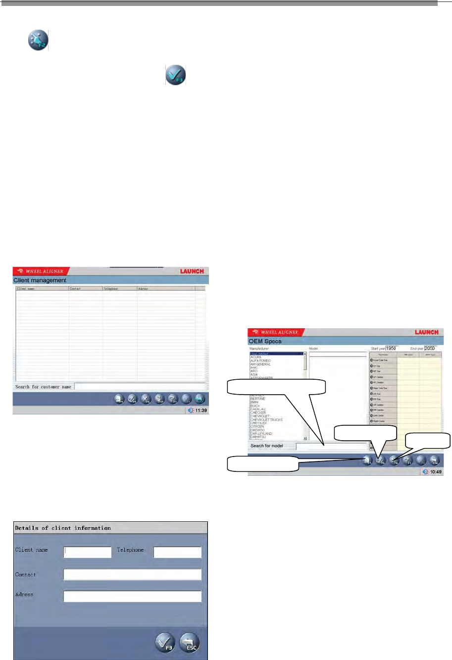
System Measurement
On the main menu, please click the icon of [System
Measurement] to enter the measurement interface as
shown in Fig.4.36.
Fig.4.36
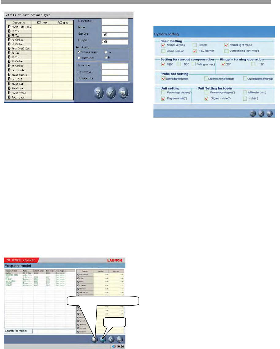
User information
<>
The information of maintenance station is mainly used
to record the contact method of the maintenance
station and the information of the maintenance
technician. This kind of information can be imported to
report forms, which can make the information of
maintenance station be displayed on the report form
printed out, and is convenient for your data
management and tracing operation. The interface is as
shown in Fig.4.37.
Fig.4.37
[Setting]: After entering this interface, the information
box will be displayed with French gray back-ground, in
Select Vehicle Model
LAUNCH X-631/X-631+ Wheel Aligner Operation Instructions
4-12
this state the system only provides view function.
Click button to perform information editing
operation.
After entering the information, please click button,
the system will automatically save the information and
return to the previous interface.
Note: If there are multi-operators for performing wheel
alignment, the input method of recording or saving the
operators' names is using "#" to separate every
operator's name. For instance,
Tom#John#Paul#Steven#.
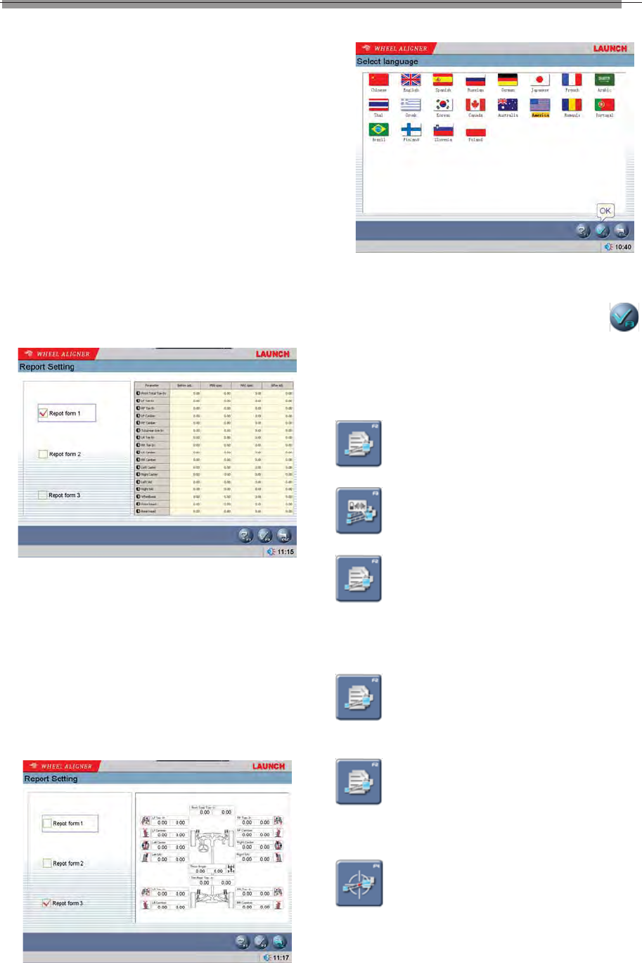
Client management:
Client information is very important in our daily routine,
so we must manage and maintain these data very well,
which can ensure us to solve the problem in time and
improve our service quality. The interface is as shown
in Fig.4.38.
Fig.4.38
[Quick search]: Directly input the first letter of the
customer name in the text box, the system will
automatically perform the search operation.
[Add]: Click this button, and then add the client
information in the pop-up window for detailed
information of the client. The interface is as shown in
Fig.4.39.
Fig.4.39
[Modify]: Select the items required to modify, and then
click this button, modifying the client information in the
popped-up window for the detailed information of client.
[Delete]: Delete the items selected in client information
data form. When performing Delete operation, please
note that Delete operation will delete all the
corresponding information (including previous testing
information) of client. Ensure that you do want to delete
the information before performing Delete operation.
[Print]: Print client information data form.
The input box for Quick search aiming at the vehicle
model provided at the bottom of the interface
OEM Specs
This interface provides the parameter information
(These parameter information has been set before the
vehicles leave factory) for the vehicles with various
models. The database contains the information of
various kinds of vehicles manufactured by many
manufacturers all over the world, and the contents in
database can be updated in time via system upgrade.
In addition, this interface provides the function of
adding the user-defined data. The operator can add by
him-self (or her-self) all the vehicle model information
which the standard database does not has. This
system is fit more for the service data application.
The interface is as shown in Fig.4.40.
Fig.4.40
[Search for model]: To provide the function of Quick
search for vehicle model. Directly input the first letter of
the model name of the vehicle under test in the text
box, the system will automatically perform the search
operation.
[Newly added]: To add the vehicle models which are
not included in the standard database. Click this button,
you can add the user-defined information in the
popped-up window (as shown in the following figure)
for the detailed information of the user-defined data.
After confirming, you can save the information into the
data list.
Quick search for model
Delete
Modify
Newly added
LAUNCH X-631/X-631+ Wheel Aligner Operation Instructions
4-13
Fig.4.41
[Modify]: This function is only applied to modifying the
user-defined information in the list. It cannot modify the
information imported from the standard data.
[Delete]: This function is only applied to deleting the
user-defined information in the list. It cannot delete the
information imported from the standard data.
Operating procedures:
Directly click manufacturer to select corresponding
vehicle model, in order to give the operator a
convenient view for the standard data of the vehicle
model.
Frequent Model
In order to speed up the information search, the system
provides the commonly used data management
function which can individually add the vehicle
information in the standard data into the commonly
used data. The interface is as shown in Fig.4.42.
Fig.4.42
[Added from the standard data]: Click this button, the
standard data window will be activated. Select the
required vehicle model from the standard data list. After
confirming, the information can be added from the
standard data to the commonly used data list.
[Delete]: Delete the items selected from the commonly
used data.
System Setting
System setting function is used to adjust the function
and display effect of software system. The interface is
as shown in Fig.4.43.
Fig.4.43
[Basic setting]: With this function the system can be
switched between Normal Version and Demo Version,
and between Special Version and Common Version.
[Normal version]: is the version directly applied in
actual testing operation; [Demo version]: this version
can, in stand-alone status, simulate the testing process
without external hardware equipments, it hasn't testing
ability, only used to demonstrate the testing process;
[Common version]: this version provides all-around
HELP information and operating demo animation to
fully help the testing personnel who contacts this
system for the first time; [Special version]: for
experienced operator, too much HELP information will,
on the contrary, become encumbrance, so this
version provides the necessary HELP information only
to make the operator be working with more high
efficiency.
[Normal mode]: It is a default mode, and used in the
case of no direct sunlight or strong ground reflection
light.
[Strong light mode]: It is used when there is direct
sunlight or strong ground reflection light.
[Setting for run-out compensation]: the system provides
three types of run-out compensation: 1) 180-degree
compensation (turning for 2 times) 2) 90-degree
compensation (turning for 4 times) 3) Rolling run-out
compensation.
[Setting for kingpin steering operation]: the system
provides two types of kingpin measurement: 1)
Steering wheel turns by 20 degrees; 2) Steering wheel
turns by 10 degrees.
[Probe rod calibration setting]: you can select all CCD
sensors or end CCD sensor to calibrate
[Probe rod setting]: When one pair of front probe rods
or rear probe rods is faulty, you can use the normal pair
of probe rods to finish the part of the test items. For
example, all four probe rods are used in normal case.
When front probe rods are faulty, you can select “Use
rear probe rods” to tell the system only to use rear
probe rods to perform the test.
Delete
A
dded from the standard data
LAUNCH X-631/X-631+ Wheel Aligner Operation Instructions
4-14
[Unit setting]: Used to set the displayed unit system of
system data, two types of unit systems can be selected:
percentage degree system and degree/minute system.
[Unit setting for toe-in]: Aiming to the particularity of the
unit for toe-in, the system adds the units of mm and
inch.
Note:
If you want to use long measure as the unit of toe-in,
during performing standard measurement, the system
will require the operator to enter the diameter of the
tires when entering the operating interface of Select
Vehicle Model.
Report setting
Report setting can set the format type of the report
form. The interface is as shown in Fig.4.44.
Fig.4.44
[Report form 1]: Format 1 is for detailed report form,
which includes the items of Before Adjustment, After
Adjustment, Standard maximum and minimum values.
[Report form 2]: Format 2 is for concise report form,
which lists the data information before and after
adjustment only.
[Report form 3]: Format 3 is for fig report form. The
interface is as shown in Fig.4.45.
Fig.4.45
Select Language
The system has provided many languages to select.
The interface is as shown in Fig.4.46
Fig.4.46
Operating procedures:
Select your desired language, and then click
button, the system will restart and switch to the interface
with the language you selected.
Probe Rod Maintenance
This function has provided six operations.
Detailed information of probe rod: Used to view
the running status of sensor inside the probe rod.
Status of probe rod: Used to view the status of
communication and electricity quantity of probe rod.
Self-test for measurement accuracy of probe
rod: Used for testing whether toe-in and camber values
measured by the probe rod currently used are correct or
not, and tell client or after-sales service personnel if the
probe rod needs to be recalibrated.
Probe rod update: Mainly used for probe rod
update service performed by after-sales service
personnel.
Electronic level correction for probe rode:
Mainly used for solving the problem of the disaccord
between electronic level and mechanical level due to
long-time use of the probe rod.
Calibration for probe rod: Used to reset the
calibration value of probe rod.
The interface is as shown in Fig.4.47.
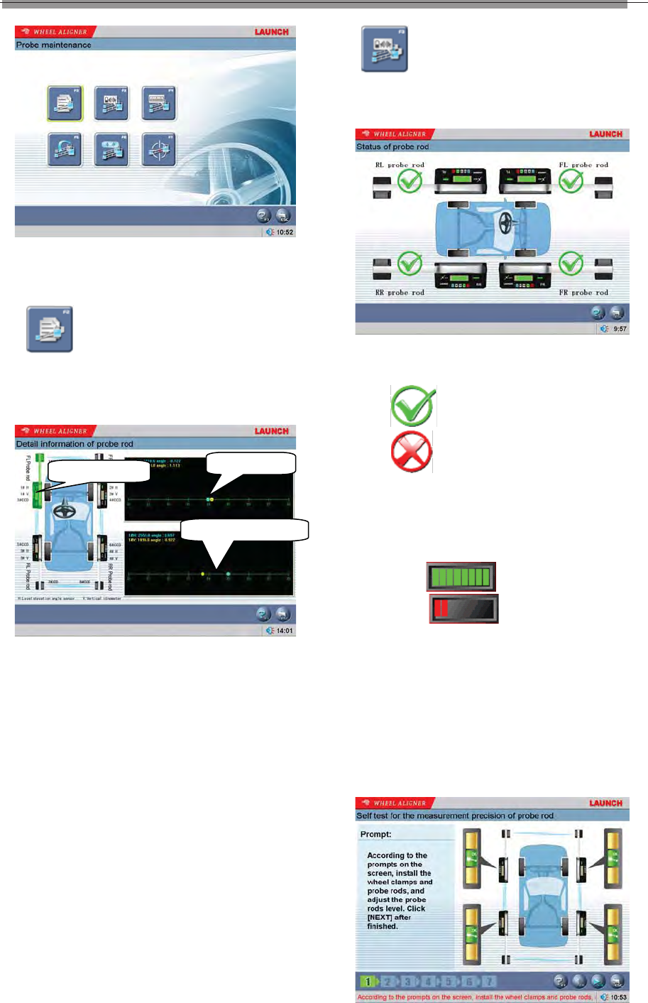
LAUNCH X-631/X-631+ Wheel Aligner Operation Instructions
4-15
Fig.4.47
Detailed Information of Probe Rod:
In the [Probe rod maintenance] interface, click the
icon to enter the interface for the detailed
information of probe rod. This interface can directly
display the running status of 8 CCD sensors and 8
clinometers inside the 4 probe rods. The interface is as
shown in Fig.4.48.
Fig.4.48
[Select probe rode]: One of the probe rods will be
displayed bright green after clicking the icon of this
probe rod.
[CCD status]: To display the coordinate and using status
of the 2 CCD sensors inside the probe rod selected.
[Inclinometer status]: To display the coordinate and
using status of the 2 inclinometers inside the probe rod
selected.
Operating procedures:
Directly click the probe rod you want to check in the
model figure at left side, the probe rod you have
selected will be highlighted, the current readings of the
four probe rods can be displayed in reading scale figure
at right side. If certain sensor cannot read data, it
indicates that this probe rod has been abnormal.
Status of probe rod:
In the [Probe rod maintenance] interface, click the
icon to enter the interface of the probe status.
Status of probe rod is used to display the
communication status between probe rod and system.
The interface is as shown in Fig.4.49.
Fig.4.49
When communication between probe rod and system is
normal, will be displayed on probe rod,
otherwise will be displayed to indicate the faulty
communication.
Also the current status of electricity quantity in probe rod
can be displayed in the case of the communication
between the probe rod and system is normal,
respectively two kinds of status are as follows:
1. Full electricity
2. Low electricity
Self-test for the Measurement Accuracy of Probe Rod
In the interface of [Probe Rod Maintenance], please click
the icon of [Self-test for Measurement Accuracy of Probe
Rod], the system will enter the interface as shown in
Fig.4.50. The probe rod measurement accuracy self-test
function is used for testing whether toe-in and camber
values measured by the probe rod currently used are
correct or not, and tell client or after-sales service
personnel if the probe rod needs to be recalibrated.
Fig.4.50
Select
p
robe CCD status
linclinometer status
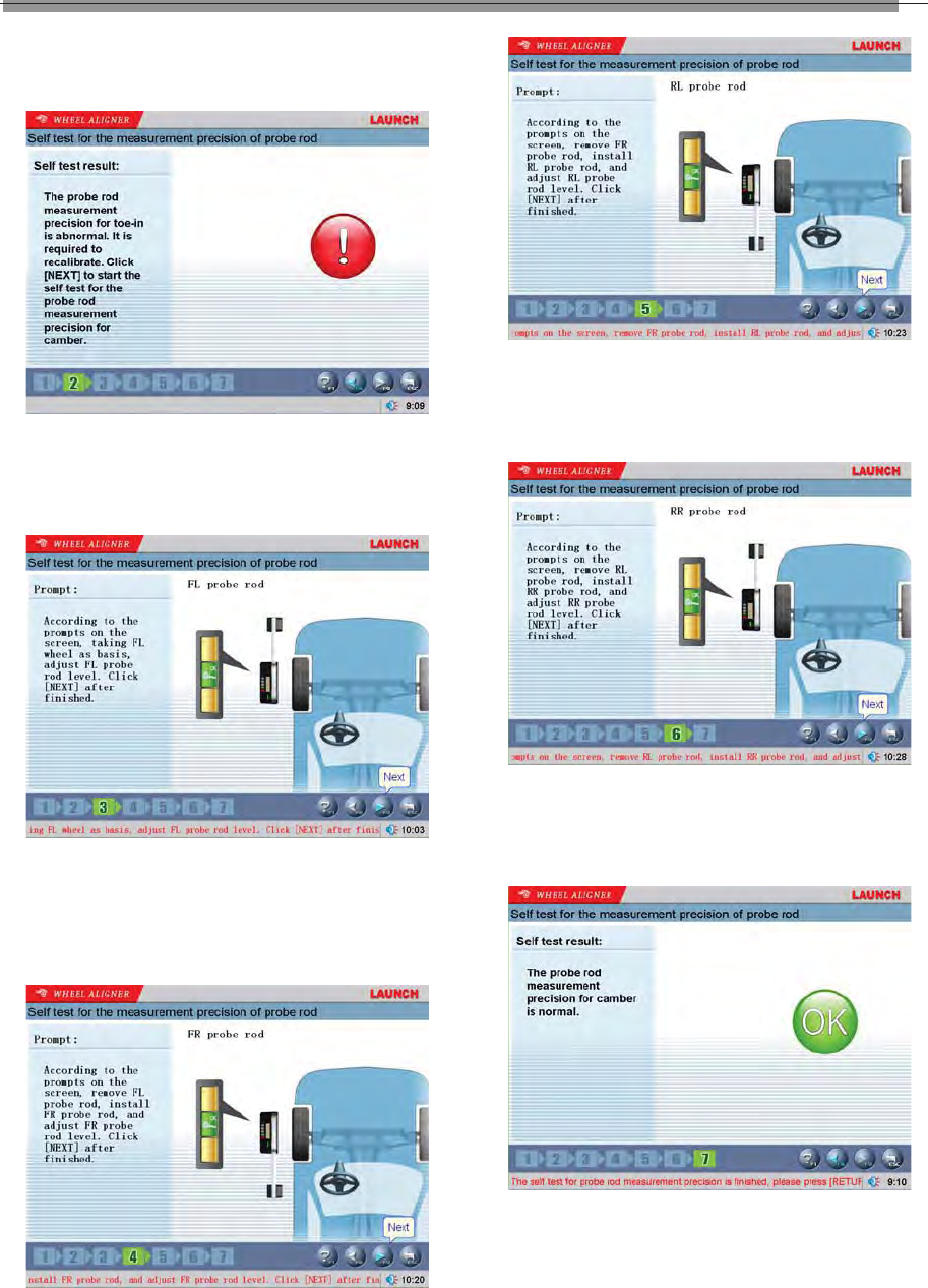
LAUNCH X-631/X-631+ Wheel Aligner Operation Instructions
4-16
According to the prompts on the screen, install 4 probe
rods on the wheels respectively, and then adjust them
level. Click [NEXT] after finished.
Fig.4.51
The screen will prompt whether the toe-in
measurement accuracy of 4 probe rods is normal or
not. If not, it is required to recalibrate.
Fig.4.52
According to the prompts on the screen, take FL wheel
as reference, install FL probe rod on FL wheel, and
then adjust the probe rod level. Click [NEXT] after
finished.
Fig.4.53
Remove FL probe rod, install FR probe rod on FL
wheel, and then adjust the probe rod level. Click [NEXT]
after finished.
Fig.4.54
Remove FR probe rod, install LR probe rod on FL
wheel, and then adjust the probe rod level. Click [NEXT]
after finished.
Fig.4.55
Remove RL probe rod, install RR probe rod on FL
wheel, and then adjust the probe rod level. Click [NEXT]
after finished.
Fig.4.56
The screen will prompt whether the camber
measurement accuracy of 4 probe rods is normal or
not. If not, it is required to recalibrate.
Caution:
This function does not need calibration frame, it can be
performed on any one of vehicles.
Probe Rod Update
In the interface of [Probe Rod Maintenance], please
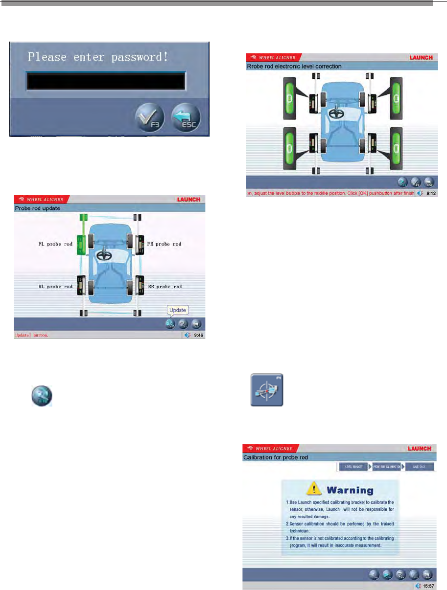
LAUNCH X-631/X-631+ Wheel Aligner Operation Instructions
4-17
click the icon of [Probe Rod Update], the screen will
pop up a password inputting box as shown in Fig.4.57.
Fig.4.57
Enter the password (provided by Launch), and then
click [OK] button to enter the interface of Probe Rod
Update as shown in Fig.4.58.
Fig.4.58
Directly click the icon of the probe rod required to
update, the probe rod icon selected will be highlighted.
Click button ˈthe screen will prompt the
operator to press, at the same time within the limited
period, the key combination of [Previous]+[Next] on the
control panel of the probe rod required to update, in
order to trigger the probe rod to accomplish the update
operation. The screen will prompt whether the probe
rod update is successful or not.
Caution:
The information such as calibration values, recognition
number, etc. of each probe rod is all stored inside the
memory of the probe rod itself. When replacing or
recalibrating the probe rod, it is required to use this
function to read the information stored inside the probe
rod and save it inside the computer host, in order to
realize the match between the probe rod and the
computer host.
Electronic Level Correction for Probe Rod
In the interface of [Probe Rod Maintenance], please
click the icon of [Electronic Level Correction for Probe
Rod], the screen will pop up a password inputting
dialog box. Enter the password (provided by Launch),
and then click [OK] button to enter the interface of
Electronic Level Correction for Probe Rod. The function
of probe rod electronic level correction is mainly used
for solving the problem of the disaccord between
electronic level and mechanical level due to long-time
use of the probe rod. The interface is as shown in
Fig.4.59.
Fig.4.59
According to the prompts on the screen, adjust the
level bubble to the middle position. Click [OK] button
after finished. The screen will prompt whether
electronic level correction for the probe rod is
successful or not.
Caution:
Before performing the operation of electronic level
correction for probe rod, it must be ensured that the
communication of 4 probe rods is normal.
Calibration for Probe Rode
In the [Probe rod maintenance] interface, click the
icon , the screen will pop up a password
inputting dialogue box. Enter password, and then click
[OK] button, the screen will display the interface as
shown in Fig.4.60.
Fig.4.60
Click [NEXT] button, the interface is as shown in
Fig.4.61.
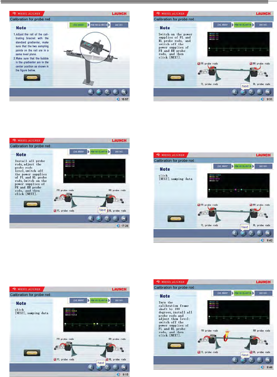
LAUNCH X-631/X-631+ Wheel Aligner Operation Instructions
4-18
Fig.4.61
According to the prompts on the screen, adjust the
calibration bracket level, and then click [NEXT] button.
The interface is as shown in Fig.4.62.
Fig.4.62
According to the prompts on the screen, install 4
probe rods and adjust them level, switch off the
power supplies FL and RL probe rods, switch on the
power supplies of FR and RR probe rods, and then
click [NEXT] button. The interface is as shown in
Fig.4.63.
Fig.4.63
According to the prompts on the screen, please click
[NEXT] button to sample data. The interface is as
shown in Fig.4.64.
Fig.4.64
According to the prompts on the screen, switch on the
power supplies of FL and RL probe rods, and switch
off the power supplies of FR and RR probe rods, and
then click [NEXT] button. The interface is as shown in
Fig.4.65.
Fig.4.65
According to the prompts on the screen, please click
[NEXT] button to sample data. The interface is as
shown in Fig.4.66.
4.66
According to the prompts on the screen, turn the
calibration frame shaft by 180 degrees, install all
probe rods and adjust them level; switch off the
power supplies of FL and RL probe rods, and then
click [NEXT]. The interface is as shown in Fig.4.67.
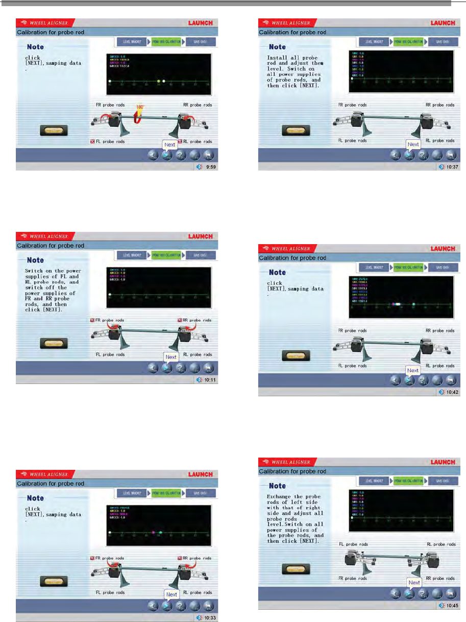
LAUNCH X-631/X-631+ Wheel Aligner Operation Instructions
4-19
Fig.4.67
According to the prompts on the screen, please click
[NEXT] button to sample data. The interface is as
shown in Fig.4.68.
Fig.4.68
According to the prompts on the screen, switch on the
power supplies of FL and RL probe rods, and switch
off the power supplies of FR and RR probe rods, and
then click [NEXT] button. The interface is as shown in
Fig.4.69.
4.69
According to the prompts on the screen, please click
[NEXT] button to sample data. The interface is as
shown in Fig.4.70.
4.70
According to the prompts on the screen, install 4
probe rods and adjust them level, switch on all power
supplies of probe rods, and then click [NEXT] button.
The interface is as shown in Fig.4.71.
Fig.4.71
According to the prompts on the screen, please click
[NEXT] button to sample data. The interface is as
shown in Fig.4.72.
Fig.4.72
According to the prompts on the screen, exchange
the probe rods of left side with that of right side and
adjust all probe rods level. Switch on all power
supplies of the probe rods, and then click [NEXT]
button. The interface is as shown in Fig.4.73.
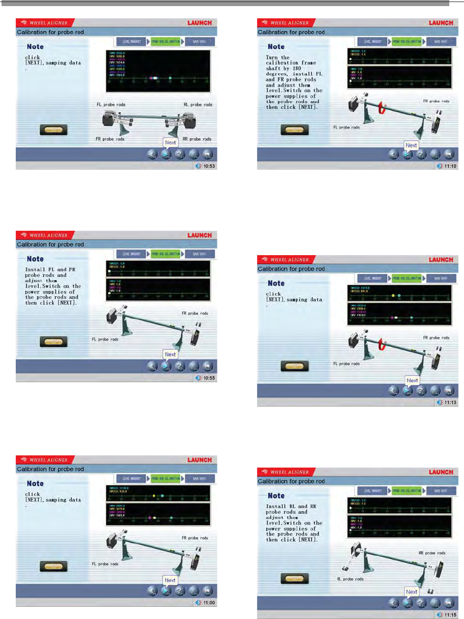
LAUNCH X-631/X-631+ Wheel Aligner Operation Instructions
4-20
Fig.4.73
According to the prompts on the screen, please click
[NEXT] button to sample data. The interface is as
shown in Fig.4.74.
Fig.4.74
According to the prompts on the screen, install FL
and FR probe rods and adjust them level. Switch on
the power supplies of the probe rods, and then click
[NEXT] button. The interface is as shown in Fig.4.75.
Fig.4.75
According to the prompts on the screen, please click
[NEXT] button to sample data. The interface is as
shown in Fig.4.76.
Fig.4.76
According to the prompts on the screen, turn the
calibration frame shaft by 180 degrees, install FL and
FR probe rods and adjust them level; switch on the
power supplies of the probe rods, and then click
[NEXT]. The interface is as shown in Fig.4.77.
Fig.4.77
According to the prompts on the screen, please click
[NEXT] button to sample data. The interface is as
shown in Fig.4.78.
Fig.4.78
According to the prompts on the screen, install RL
and RR probe rods and adjust them level; switch on
the power supplies of the probe rods, and then click
[NEXT]. The interface is as shown in Fig.4.79.
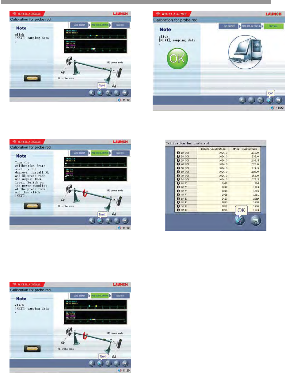
LAUNCH X-631/X-631+ Wheel Aligner Operation Instructions
4-21
Fig.4.79
According to the prompts on the screen, please click
[NEXT] button to sample data. The interface is as
shown in Fig.4.80.
Fig.4.80
According to the prompts on the screen, turn the
calibration frame shaft by 180 degrees, install RL and
RR probe rods and adjust them level; switch on the
power supplies of the probe rods, and then click
[NEXT]. The interface is as shown in Fig.4.81.
Fig.4.81
According to the prompts on the screen, please click
[NEXT] button to sample data. The interface is as
shown in Fig.4.82.
Fig.4.82
Click [OK] button to display the calibration value
changes. The interface is as shown in Fig.4.83.
Fig.4.83
Click [OK] button to finish whole calibration
procedures.
(Caution: If only all calibrated values are not equal to
zero, it indicates that the calibration is successful this
time; If the calibrated value of any one of ˟˟ˠ
and inclinometer is equal to zero, it indicates that the
calibration is not successful this time, and it is
required to recalibrate. Many factors can result in
unsuccessful probe rod calibration, but it is mainly
caused by inappropriate calibration operation or
hardware fault.)
Note:
The equipment must be calibrated before leaving
factory, in order to make the default parameter inside
the probe rod be set to standard value. Generally
speaking, the calibration operation for probe rod can
be performed in the following three cases:
1. The calibration operation for probe rod can be
performed after the equipment has been used for one
or more than one year.
2. The calibration operation for probe rod can be
performed in the case of the equipment has been
impacted ever and the test readings are not up to the
standard.
3. The calibration operation for probe rod can be
performed in the case of the sensor was faulty and
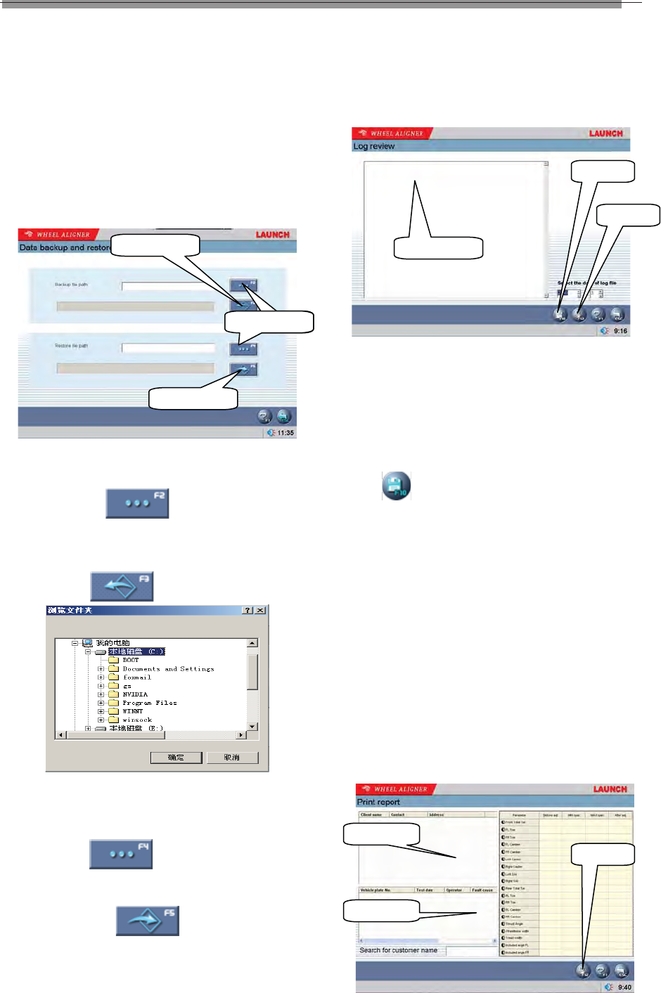
LAUNCH X-631/X-631+ Wheel Aligner Operation Instructions
4-22
the sensor replacement operation has been
performed ever.
Data backup and restore
The function is used in system data backup application,
so as to prevent the WINDOWS system from abnormity
caused by external factors (such as virus), and help
you to avoid unnecessary loss. The backup function we
provide is mainly used to backup the contents of three
parts: user and business data information, system
configuration file and probe calibration information. The
interface is as shown in Fig.4.84.
Fig.4.84
Operating procedures:
1. Backup: Click button, find the position
of the file you expect to save in pop-up dialogue box
(The interface is as shown in Fig.4.82) or enter the
path address directly in the blank of exported file path,
and then click button finally.
Fig.4.85
2. Restore: The similar operation can be performed
when the backed-up data need to be imported into the
system. Click button, find the position of
the file you expect to import in popped-up window or
enter the path address directly in the blank of imported
file path, then click button, the system will
automatically import this back-up file.
Log Review
Log is the important recorded information for the system
running. We can check the system conditions by viewing
the log, so we can say that the log is an important
window for us to monitor and diagnose the system.
During running and testing operation, the system will
record some main operations or signals, in this way the
information records in log file are built. The interface is
as shown in Fig.4.86.
Fig.4.86
Operating procedures:
[Log column]: To shown the abnormal conditions of the
equipment usage in each year.
[Save]: When there are records in the log file of system,
the required records can be saved by
clicking button, and viewed by technical personnel,
checking the running conditions of equipment.
[Print]: The system has provided the printing function
which is convenient to view.
Note:
Besides the client information needs backup operation
regularly, we recommend that the log records need
back-up operation regularly, too, so as to be convenient
to repair and maintain the equipment.
Print
In main interface, click the icon of [Print] to enter the
interface of repot form print. It is mainly used to check
or print the normal testing records of the client. The
interface is as shown in Fig.4.87.
Fig.4.87
Select path
Start to backup
Start to restore
Log column
Save
Print
Print
Client list
Record list
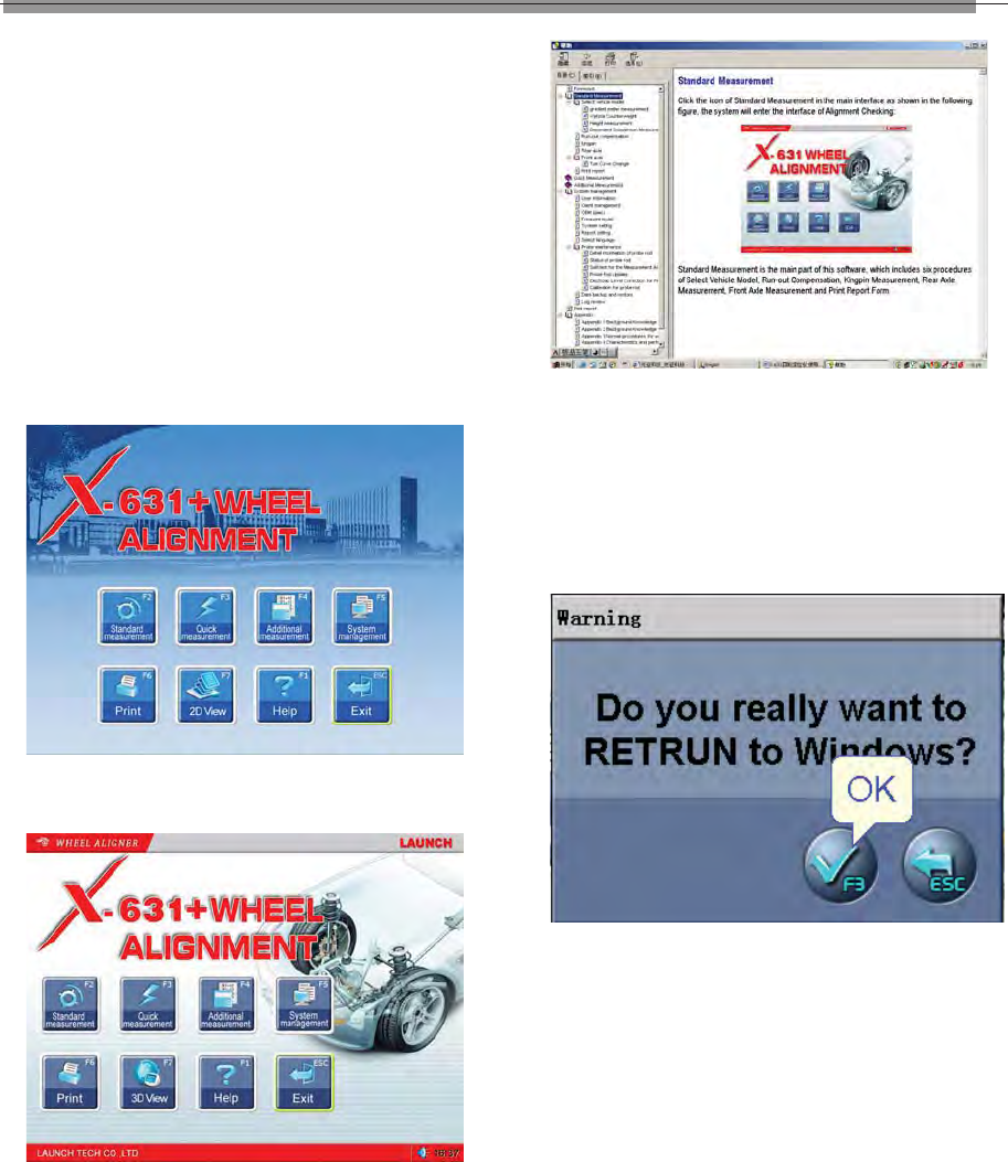
LAUNCH X-631/X-631+ Wheel Aligner Operation Instructions
4-23
[Client list]: To list the all clients who have been
serviced by the alignment test.
[Record list]: This list can display the alignment test
records (for one time or many times) of the client
selected from [Client list].
[Print]: To print the alignment data of the vehicle
under test with form or figure format (Please refer to
[System Management] – [Report Setting] for the
format setting of report form).
3D Interface / 2D Interface
3D Interface is as shown in Fig.4.88.
Fig.4.88
2D Interface is as shown in Fig.4.89.
Fig.4.89
Help
HELP system provides more detailed operating
descriptions. The interface is as shown in Fig.4.90.
Fig.4.90
Exit
EXIT system has two kinds of prompts: Exit from the
system and return to WINDOWS operating interface
or Exit and shutdown (Please refer to [System
Management] – [System Setting] for the detailed
settings). The interface is as shown in Fig.4.91.
Fig.4.91
New Functions of X-631+ Wheel Aligner
Added Functions for X-631+ Wheel Aligner
No PC Mode and the corresponding functions are
added. That is to say, without the help of computer,
you can perform the corresponding operations on the
probe rods in order to realize the basic functions of
wheel alignment. Now, you can get the data of
camber and toe-in under this No PC Mode.
The computer (main unit) is of the master control
equipment of the former wheel aligner, and the
calculation and display, etc. are all performed on the
main unit.
Working mode with computer: In this mode, you can
perform the wheel alignment operation with the
control of the computer. X-631 wheel aligner uses this
working mode.
No computer working mode (No PC Mode): In this
mode, you can use the probe rods to perform the
wheel alignment operation without the help of the
computer. X-631+ wheel aligner is added with this
function.
X-631+ wheel aligner No PC Mode has 4 kinds as
follows:
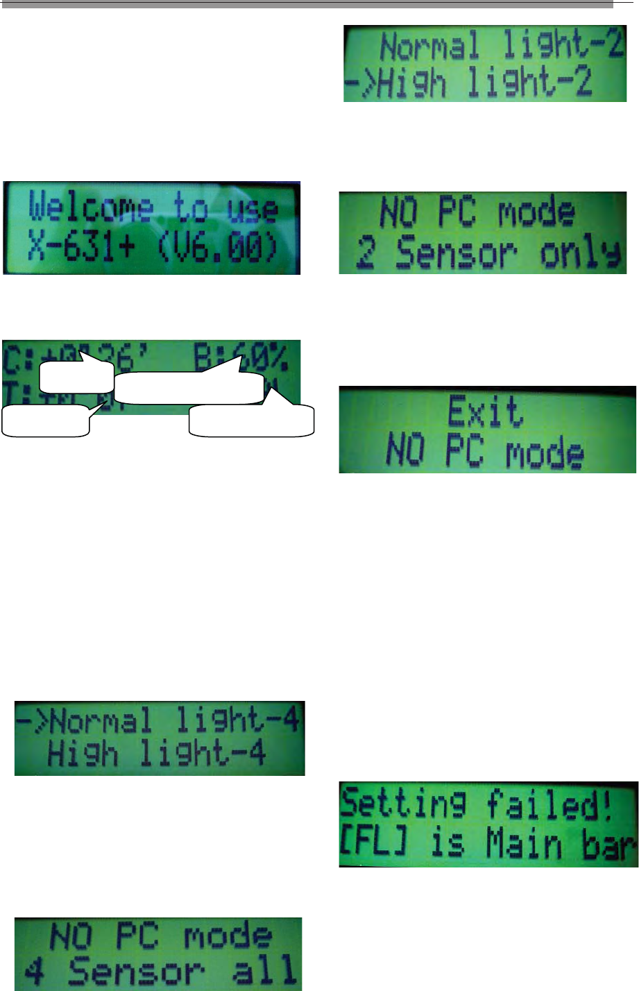
LAUNCH X-631/X-631+ Wheel Aligner Operation Instructions
4-24
1. Four-probe rode normal light mode (Normal
light-4);
2. Four-probe rod high light mode (High light-4);
3. Two-probe rod normal light mode (Normal
light-2);
4. Two-probe rod high light mode (High light-2).
These four kinds of mode are same with that on the
computer.
The start-up interfaces of the probe rods are different:
Fig.4.92
The main working interfaces are different:
Fig.4.93
Operation Instructions for X-631+ Wheel Aligner
First, please enter into No PC Mode of X-631+ wheel
aligner.
After the probe rods entering the main working
interfaces, please press down the keys of [Back Light]
and [Run-out Compensation] at the same time, you
can enter the selection interface of No PC Mode.
There are four kinds of working modes for selection.
Press key [Previous] or key [Next] to select the
desired mode among these four modes. The mode
pointed by the arrow head is the mode selected
currently. After selecting working mode, please press
down key [Previous] and [Next] at the same time to
enter No PC Mode.
Fig.4.94
The above interface is the No PC Mode selection
interface. Move arrow head to point to the desired
item. After selecting working mode, please press
down key [Previous] and [Next] at the same time to
enter the prompt interface for four-probe rod working
mode of No PC Mode.
Fig.4.95
Fig.4.96
After selecting working mode, please press down key
[Previous] and [Next] at the same time to enter No PC
Mode (Two-probe rod working mode).
Fig.4.97
On main probe rod, please press key [Back Light] and
key [Run-out Compensation] at the same time to exit
No PC Mode. The screen will display Exit NO PC
Mode.
Fig.4.98
Some Explanations about No PC Mode of X-631+
Wheel Aligner
1. The probe rod via which the system enters No
PC Mode is of the main probe rod. The main
probe rod can perform the control functions
(just like main unit) under No PC Mode.
2. One set of probe rods has one main probe rod
only.
3. The label of the main probe rod is included
with square brackets ([ ]). For example, [FL]:
It indicates that FL is of the current main
probe rod.
4. If this set of probe rods has had the main
probe rod, the other probe rod cannot be set
as the main probe rod once more. If you force
to do it, the error prompts will be displayed.
Fig.4.99
Error prompts: Setting failed! [XX] is Main bar.
5. After entering main working interface, the
camber data will usually be displayed. Only
after entering No PC Mode can the toe-in data
be displayed. The toe-in data will become
invalid after the system exits No PC Mode.
Battery electricity Qty.
Probe rod label Toe-in
Camber

LAUNCH X-631/X-631+ Wheel Aligner Operation Instructions
4-25
6. When the data of camber and toe-in is valid,
the corresponding data will be displayed;
when invalid, “-----” will be displayed.
7. When the system uses two-probe rod working
mode, toe-in is of total toe-in, indicated by
“TT”; when the system uses four-probe rod
working mode, toe-in is of individual toe-in,
indicated by “T”.
8. When X-631+ wheel aligner uses No PC
Mode, the displayed data units of camber and
toe-in are all in Degree/Minute mode.
9. X-631+ wheel aligner supports all functions of
X-631 wheel aligner. When the computer is
put into work, the probe rod will automatically
exit No PC Mode.

LAUNCH X-631/X-631+ Wheel Aligner Maintenance
5-1
Maintenance
To prolong the life of the equipment, users should
maintain it with care. The Wheel Aligner is precision
equipment. Here we will tell you the general
knowledge about equipment maintenance.
Computer
zUser should have a basic knowledge about
computer software and hardware to insure the
normal operation of the computer.
zThe main unit and the monitor should be firmly
placed on the desk. Do not put them in a
freezing, wet, extremely hot place or expose
them to direct sunlight, or near the source of
radiation and heat.
zDon’t foist anything into the main unit and the
monitor through the gap.
zDon’t move the computer during operation.
zDo not switch on/off the computer too frequently.
zDon’t change the BIOS setting at will.
zDon’t delete the unknown files in the hard disc at
will to avoid abnormal computer operation or
dead.
zThe computer is wholly used for the Wheel
Aligner; don’t install other software to the Wheel
Aligner computer to avoid computer virus. The
computer is checked to ensure it is free of virus
before leaving factory.
zDon’t use other software to avoid possible virus.
LAUNCH warranty does not cover the system
problem arising from the virus.
zAfter a long period of use, the dust and oil dirt
will be accumulated on the main unit and the
monitor. Please cleanout it with neutral
detergent or dehydrated alcohol. Avoid using oil
or caustic product.
zNever disassemble the computer and move the
inside cables and cards to avoid damage of the
inside components.
Wheel Clamp and Probe Rod
zThe wheel clamp should be cleaned and
lubricated timely to insure that the span of claws
can be easily adjusted and the probe rod can be
attached easily.
zThe housing of the sensor probe rod is made up
of Aluminum and plastic, after a long period of
use, the dust and oil dirt will be accumulated on
the surface, please cleanout it with neutral
detergent or dehydrated alcohol. Avoid using oil
or caustic product.
zThe sensor probe rod is a precision component;
please take care while using it. Tampering with it
may cause damage of the internal units and thus
affect its normal operation.
zEnsure that the clamp have been firmly secured
before installing the probe rod and connecting
the power connector. After finishing test,
disconnect the power first.
zDon’t disassemble the sensor probe rod to avoid
damage of its elements. LAUNCH will not
guarantee for this kind of failure.
Printer
zRead the operation instruction of the printer
carefully.
zInstall suitable printer drive program, and apply
right printer setting.
zIf the printed words are not clear, it may be that
the ink is used out. Please replace the printer ink
cartridge in time to resume the printing quality.
zFor other printer related problems, please
contact the LAUNCH Customer Service Center.

LAUNCH
Warranty
THIS WARRANTY IS EXPRESSLY LIMITED TO
PERSONS WHO PURCHASE LAUNCH PRODUCTS
FOR PURPOSES OF RESALE OR USE IN THE
ORDINARY COURSE OF THE BUYER’S
BUSINESS.
LAUNCH electronic product is warranted against
defects in materials and workmanship for one year
(12 months) from date of delivery to the user. This
warranty does not cover any part that has been
abused, altered, used for a purpose other than for
which it was intended, or used in a manner
inconsistent with instructions regarding use. The
exclusive remedy for any automotive meter found to
be defective is repair or replacement, and LAUNCH
shall not be liable for any consequential or incidental
damages. Final determination of defects shall be
made by LAUNCH in accordance with procedures
established by LAUNCH. No agent, employee, or
representative of LAUNCH has any authority to bind
LAUNCH to any affirmation, representation, or
warranty concerning LAUNCH automotive meters,
except as stated herein.
Disclaimer
THE ABOVE WARRANTY IS IN LIEU OF ANY
OTHER WARRANTY, EXPRESSED OR IMPLIED,
INCLUDING ANY WARRANTY OF
MERCHANTABILITY OR FITNESS FOR A
PARTICULAR PURPOSE.
Order Information
Replaceable and optional parts can be ordered
directly from your LAUNCH authorized tool supplier.
Your order should include the following information:
1. Quantity
2. Part number
3. Item description
Customer Service
If you have any questions on the operation of the unit,
please call: 86-755-84528288, or fax:
86-755-84528872.
If your unit requires repair service, return it to the
manufacturer with a copy of the sales receipt and a
note describing the problem. If the unit is determined
to be in warranty, it will be repaired or replaced at no
charge. If the unit is determined to be out of warranty,
it will be repaired for a nominal service charge plus
return freight. Send the unit pre-paid to:
Attn: Customer Service Center
Shenzhen Launch Tech. Co., Ltd.
Launch Industrial Park,
North of Wuhe Rd.,
Banxuegang, Longgang,
Shenzhen, Guangdong,
P. R. China
)&&67$7(0(17
7KLVGHYLFHFRPSOLHVZLWK3DUWRIWKH)&&5XOHV2SHUDWLRQLVVXEMHFWWRWKHIROORZLQJWZR
FRQGLWLRQV
7KLVGHYLFHPD\QRWFDXVHKDUPIXOLQWHUIHUHQFH
7KLVGHYLFHPXVWDFFHSWDQ\LQWHUIHUHQFHUHFHLYHGLQFOXGLQJLQWHUIHUHQFHWKDWPD\FDXVH
XQGHVLUHGRSHUDWLRQ
&KDQJHVRUPRGLILFDWLRQVQRWH[SUHVVO\DSSURYHGE\WKHSDUW\UHVSRQVLEOHIRUFRPSOLDQFHFRXOG
YRLGWKHXVHUVDXWKRULW\WRRSHUDWHWKHHTXLSPHQW
127(7KLVHTXLSPHQWKDVEHHQWHVWHGDQGIRXQGWRFRPSO\ZLWKWKHOLPLWVIRUD&ODVV%GLJLWDO
GHYLFHSXUVXDQWWR3DUWRIWKH)&&5XOHV7KHVHOLPLWVDUHGHVLJQHGWRSURYLGHUHDVRQDEOH
SURWHFWLRQDJDLQVWKDUPIXOLQWHUIHUHQFHLQDUHVLGHQWLDOLQVWDOODWLRQ
7KLVHTXLSPHQWJHQHUDWHVXVHVDQGFDQUDGLDWHUDGLRIUHTXHQF\HQHUJ\DQGLIQRWLQVWDOOHGDQG
XVHGLQDFFRUGDQFHZLWKWKHLQVWUXFWLRQVPD\FDXVHKDUPIXOLQWHUIHUHQFHWRUDGLRFRPPXQLFDWLRQV
+RZHYHUWKHUHLVQRJXDUDQWHHWKDWLQWHUIHUHQFHZLOOQRWRFFXULQDSDUWLFXODULQVWDOODWLRQ,IWKLV
HTXLSPHQWGRHVFDXVHKDUPIXOLQWHUIHUHQFHWRUDGLRRUWHOHYLVLRQUHFHSWLRQZKLFKFDQEH
GHWHUPLQHGE\WXUQLQJWKHHTXLSPHQWRIIDQGRQWKHXVHULVHQFRXUDJHGWRWU\WRFRUUHFWWKH
LQWHUIHUHQFHE\RQHRUPRUHRIWKHIROORZLQJPHDVXUHV
ǂ 5HRULHQWRUUHORFDWHWKHUHFHLYLQJDQWHQQD
ǂ ,QFUHDVHWKHVHSDUDWLRQEHWZHHQWKHHTXLSPHQWDQGUHFHLYHU
ǂ &RQQHFWWKHHTXLSPHQWLQWRDQRXWOHWRQDFLUFXLWGLIIHUHQWIURPWKDWWRZKLFKWKHUHFHLYHULV
FRQQHFWHG
ǂ &RQVXOWWKHGHDOHURUDQH[SHULHQFHGUDGLR79WHFKQLFLDQIRUKHOS